

Page 1

Document #98263100
Install Guide
Sled Dynamometer Hub Replacement
Dynojet®Research Inc.
Revision B 7/21/99
Page 2

Revision B 7/21/99 Document #
98263100
Contents
Dynojet Sled Dynamometer Hub Replacement
Be sure that you kit includes the following components. If there are
parts missing, call Dynojet Research at (406) 388-5255.
A - (1) Dyno Hubs / Shaft Assembly
B - (2) Outside Hubs for Driver Set (Modified)
C - (2) “Red” Shafts
D - (2) “Green” Shafts
A
B
D
C
Page 3
Document #98263100
1
Install Guide
Dynojet Sled Dynamometer Hub Replacement
The following steps will guide you through the replacement of the hubs
on your sled dynamometer.
Step 1
Remove the guards.
• Remove the track guard.
• Loosen the button head cap screws on the guards.
• Pull the guards off the arms.
Note: Do Not Loosen the chain tensioner bolts !
Warning: Do Not remove the parts from the spline shaft. The hubs
are setup and ready to install.
Page 4

2 Document #
98263100
Step 2
Remove the Sprocket Ends containing the old hubs.
• Loosen the 1/2" x 41/2" bolts on the front end of the arms.
• Remove the front bolts and swing the arms down.
• Remove the rear bolts and remove the arms.
Step 3
Place the new sprocket ends in the hanging chains.
Page 5

Document #98263100
3
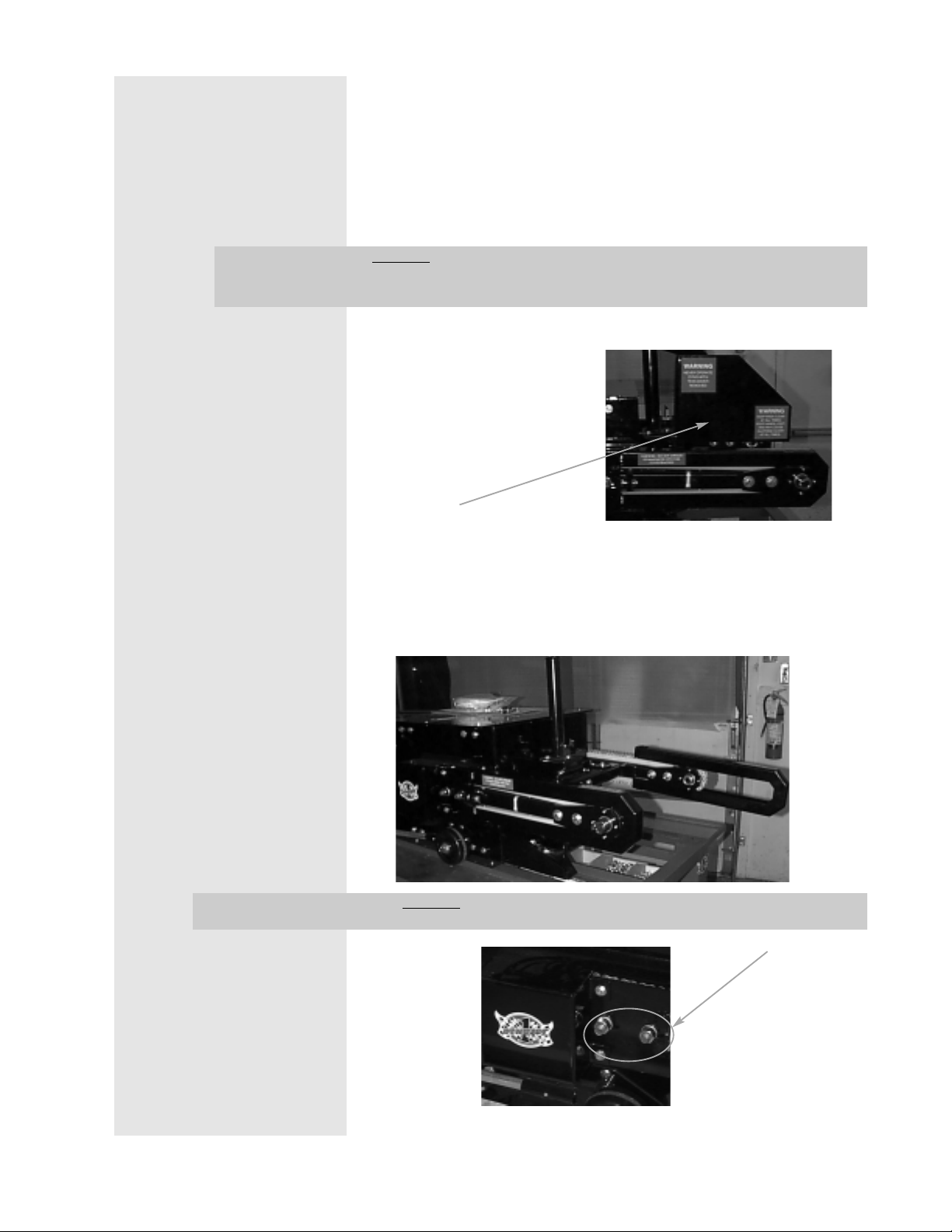
Step 4
Attach the new sprocket ends to the dyno.
• Put one 1/2" x 41/2" bolt with a 7/
16”
flat washer through each
sprocket end and the rear hole in the dyno arms. Fasten loosely.
• Allow the sprocket ends to hang as in the picture below.
• Pull the chains straight down and tightly against the hanging
sprockets.
• Swing both sprocket ends on the shaft up and put in the front
1
/2" x 41/2" bolts with 7/
16”
flat washers.
Important:
Make sure that the gears on the sprockets are in the chain at
the same point on both sides!!
Page 6

4 Document #
98263100
• Use a 7/
16”
flat washer ,1/2” lock washer and 1/2” locking nut on
each bolt and snug down.
• Rotate the shaft until it slides easily side to side.
• Tighten all four bolts to 70 ft. lbs.
• Make sure that the shaft still slides easily from side to side
between the sprocket ends.
• Remove the shaft.
Step 5
Check chain alignment in plastic chain guides. Tap guides as
needed (with a rubber hammer) to center them with the chain.
Step 6
Replace the metal arm guards and the track guard.
Note:
The bolts on the back bearing cover may need to be
loosened in order to line up the holes for the button head
cap screws on the arm guards.
Page 7

Document #98263100
5
Warning: When replacing the Outside Driver Hub, notice a punch
mark on the edge of the hub. This punch mark should
be directly opposite of the alignment hole in the Outside
Driver. Be sure that when you install the new Outside
Driver Hub and Outside Driver that these holes are
directly opposite of each other.
Improper alignment of the outside Driver Hub and Driver
will not allow you to assemble the driver set correctly.
Punch Mark
Be sure that the punch mark and alignment hole are
directly opposite of each other !!
Step 7
Assemble the driver set and then install it on the dyno. If the
driver set is assembled properly, the shafts should slide in
without complication.
•
If you have any questions, or need
technical assistance, call (406) 388-5255.
 Loading...