

Page 1

Page 2

©2010-2011 Dynojet Research, Inc. All Rights Reserved.
#
RECORD
Installation Guide For Model SD12 Scooter Dynamometers.
This manual is copyrighted by Dynojet Research, Inc., hereafter referred to as Dynojet,
and all rights are reserved. This manual is furnished under license and may only be used
or copied in accordance with the terms of such license. This manual is furnished for
informational use only, is subject to change without notice, and should not be construed
as a commitment by Dynojet. Dynojet assumes no responsibility or liability for any error
or inaccuracies that may appear in this manual. Except as permitted by such license, no
part of this manual may be reproduced, stored in a retrieval system, or transmitted, in any
form or by any means, electronic, mechanical, recording, or otherwise, without the prior
written permission of Dynojet.
The Dynojet logo is a trademark of Dynojet Research, Inc.
Any trademarks, trade names, service marks, or service names owned or registered by any
other company and used in this guide are the property of their respective companies.
Dynojet Research, Inc., 2191 Mendenhall Drive, North Las Vegas, Nevada 89081, USA.
Printed in USA.
Part Number: 98200024 Version 3 (05/2011)
Dynamometer Number: ____________________________________________________
Page 3

T
ABLE OF
C
ONTENTS
Warnings . . . . . . . . . . . . . . . . . . . . . . . . . . . . . . . . . . . . . . . . . . . . . . . . iii
Chapter 1 Specifications and Operating Requirements
Introduction . . . . . . . . . . . . . . . . . . . . . . . . . . . . . . . . . . . . . . . . . . . . . . . . . .1-2
Conventions Used In This Manual . . . . . . . . . . . . . . . . . . . . . . . . . . . . . . .1-2
Technical Support . . . . . . . . . . . . . . . . . . . . . . . . . . . . . . . . . . . . . . . . . . . 1-2
Your Dyno Room . . . . . . . . . . . . . . . . . . . . . . . . . . . . . . . . . . . . . . . . . . . . 1-3
Dynamometer Specifications and Requirements . . . . . . . . . . . . . . . . . . . .1-4
Chassis Specifications . . . . . . . . . . . . . . . . . . . . . . . . . . . . . . . . . . . . . . . . . 1-4
Compressed Air Requirements . . . . . . . . . . . . . . . . . . . . . . . . . . . . . . . . . .1-6
Computer Specifications . . . . . . . . . . . . . . . . . . . . . . . . . . . . . . . . . . . . . .1-6
Environmental Requirements . . . . . . . . . . . . . . . . . . . . . . . . . . . . . . . . . . .1-6
Forklift Requirements . . . . . . . . . . . . . . . . . . . . . . . . . . . . . . . . . . . . . . . . . 1-6
Phone and Internet Access . . . . . . . . . . . . . . . . . . . . . . . . . . . . . . . . . . . . .1-6
Tie-Down Straps . . . . . . . . . . . . . . . . . . . . . . . . . . . . . . . . . . . . . . . . . . . .1-6
Dyno Electronics . . . . . . . . . . . . . . . . . . . . . . . . . . . . . . . . . . . . . . . . . . . . . .1-7
Chapter 2 Installation
Unpacking the Dyno . . . . . . . . . . . . . . . . . . . . . . . . . . . . . . . . . . . . . . . . . . . 2-2
Unpacking the Dyno . . . . . . . . . . . . . . . . . . . . . . . . . . . . . . . . . . . . . . . . .2-2
Removing the Drum from the Crate . . . . . . . . . . . . . . . . . . . . . . . . . . . . . .2-3
Installation . . . . . . . . . . . . . . . . . . . . . . . . . . . . . . . . . . . . . . . . . . . . . . . . . . .2-4
Installing the Front Support . . . . . . . . . . . . . . . . . . . . . . . . . . . . . . . . . . . .2-4
Routing Cables . . . . . . . . . . . . . . . . . . . . . . . . . . . . . . . . . . . . . . . . . . . . .2-7
Wiring the Breakout Board . . . . . . . . . . . . . . . . . . . . . . . . . . . . . . . . . . . . .2-8
Installing the Ramp . . . . . . . . . . . . . . . . . . . . . . . . . . . . . . . . . . . . . . . . . . 2-9
Fold and Move the Dyno . . . . . . . . . . . . . . . . . . . . . . . . . . . . . . . . . . . . . .2-10
Folding the Dyno . . . . . . . . . . . . . . . . . . . . . . . . . . . . . . . . . . . . . . . . . . .2-10
Moving the Dyno . . . . . . . . . . . . . . . . . . . . . . . . . . . . . . . . . . . . . . . . . .2-11
Opening the Dyno . . . . . . . . . . . . . . . . . . . . . . . . . . . . . . . . . . . . . . . . . .2-12
Accessories . . . . . . . . . . . . . . . . . . . . . . . . . . . . . . . . . . . . . . . . . . . . . . . . . .2-13
Compressed Air Pump Assembly . . . . . . . . . . . . . . . . . . . . . . . . . . . . . . .2-13
Stand Alone Blowers . . . . . . . . . . . . . . . . . . . . . . . . . . . . . . . . . . . . . . . . 2-13
Model SD12 Scooter Dynamometer Installation Guide
i
Page 4

TABLE OF CONTENTS
Chapter 3 Basic Dyno Operation
Loading the Vehicle . . . . . . . . . . . . . . . . . . . . . . . . . . . . . . . . . . . . . . . . . . .3-2
Connecting the RPM Pickup . . . . . . . . . . . . . . . . . . . . . . . . . . . . . . . . . . . .3-4
RPM Pickup Descriptions . . . . . . . . . . . . . . . . . . . . . . . . . . . . . . . . . . . . . .3-4
Connecting the Secondary Inductive Pickup . . . . . . . . . . . . . . . . . . . . . . .3-5
Connecting The Primary Inductive Pickup . . . . . . . . . . . . . . . . . . . . . . . . . 3-6
Pre-Run Inspection . . . . . . . . . . . . . . . . . . . . . . . . . . . . . . . . . . . . . . . . . . . .3-7
Before Starting the Engine . . . . . . . . . . . . . . . . . . . . . . . . . . . . . . . . . . . . .3-8
Engine Warm Up . . . . . . . . . . . . . . . . . . . . . . . . . . . . . . . . . . . . . . . . . . . .3-8
After Engine Warm Up . . . . . . . . . . . . . . . . . . . . . . . . . . . . . . . . . . . . . . . .3-8
Making a Test Run . . . . . . . . . . . . . . . . . . . . . . . . . . . . . . . . . . . . . . . . . . . . 3-9
Preventative Maintenance . . . . . . . . . . . . . . . . . . . . . . . . . . . . . . . . . . . . .3-10
Adjusting the Brake . . . . . . . . . . . . . . . . . . . . . . . . . . . . . . . . . . . . . . . . . 3-10
Adjusting the Brake Tension . . . . . . . . . . . . . . . . . . . . . . . . . . . . . . . . . . .3-11
Index . . . . . . . . . . . . . . . . . . . . . . . . . . . . . . . . . . . . . . . . . . . . . . . . . Index-i
ii
Model SD12 Scooter Dynamometer Installation Guide
Page 5

W
ARNINGS
Disclaimers
Dynojet Research, Inc. (Dynojet) makes no representation or warranties with respect to the contents
hereof and specifically disclaims any implied warranties of merchantability for any particular purpose.
Dynojet reserves the right to revise this publication and to make changes from time to time in the
content hereof without obligation of Dynojet to notify any person of such revision or changes.
Dynojet is not responsible for false operation due to unexpected dynamometer operation such as may
be caused by static, software bugs, hardware failure, etc.
Dynojet is not responsible for damage resulting from improper installation of the dynamometer or
from improper service rendered to the dynamometer. Dynojet is not responsible for damage incurred
due to alteration of the dynamometer or components, use of unapproved parts, or abuse to the
dynamometer.
Do not connect or disconnect cables or components on the dynamometer with the power on.
Always wear protective clothing, ear protection, and eye protection (goggles, safety glasses) when
using and servicing the dynamometer.
Equipment Power Requirements
The dynamometer has specific power requirements. Connecting the dynamometer to the incorrect
voltage will void the dynamometer warranty. Installation may require a licensed electrician.
Potentially Lethal Voltages
Components attached to and within the dynamometer operate with potentially lethal voltages. To
provide the greatest assurance of safety, the AC power cord(s) must be disconnected from the power
source before servicing electrical components or wiring. Disconnect all power cords before servicing
electrical components for the greatest assurance of safety.
Model SD12 Scooter Dynamometer Installation Guide
iii
Page 6

WARN IN GS
Electrostatic Discharge Precautions
Electrostatic Discharge
Electrostatic Discharge (ESD), or static shock, can damage electronic components within the
dynamometer. The damage may occur at the time of an ESD occurrence, or the shock may degrade
the component, resulting in a premature component failure later. To avoid ESD damage, always
practice good ESD control precautions when servicing the dynamometer. Dynojet designs its
dyn amo me ter s to be v er y to ler ant of sta tic sho ck s by the users, but the electronics are vulnerable when
the electronics are exposed. ESD occurs as a result of a difference of potential between two objects
when the two objects touch. Damage occurs as a result of the energy released when the discharge
(touch) occurs. The difference of potential can accumulate by as simple an action as a user moving
across carpet or a seat. If that person’s energy is discharged directly to the electronics, the electronics
can be damaged.
Precautions
To protect against ESD damage, you must eliminate the difference of potential before the electronics
are handled. Touch the chassis of the dynamometer before touching any of the electronics. By touching
the chassis, you discharge any static shocks to the chassis instead of to the electronics.
If you are holding a circuit board or dynamometer component in your hand when you approach the
machine, touch the chassis of the dynamometer with your hand before installing the circuit board or
component.
When handing a circuit board or component to someone, touch that person with your hand first, then
hand them the component.
Always carry circuit boards in anti-static bags when the boards are exposed (removed from the
dynamometer).
Battery Fire and Explosion Hazards
There is a danger of explosion if the battery is incorrectly replaced. Replace only with the same or
equivalent type recommended by the manufacturer. Discard used batteries according to the
manufacturer’s instructions.
Automotive Batteries
In operation, batteries generate and release flammable hydrogen gas. They must always be assumed
to contain this gas which, if ignited by burning cigarette, naked flame or spark, may cause battery
explosion with dispersion of casing fragments and corrosive liquid electrolyte. Carefully follow
manufacturer's instructions for installation and service. Keep away all sources of gas ignition and do
not allow metallic articles to simultaneously contact the negative and positive terminals of a battery.
Do not allow the positive and negative terminals to short-circuit. The dynamometer chassis is tied to
the negative side of the battery. Do not short between the positive battery terminal or the starter
connections to the chassis. In addition, make sure metal tools such as screw drivers, wrenches, and
torque wrenches do not come in contact with the negative and positive terminals of the battery. Short
circuiting the terminals of the battery can cause burn injuries, damage to the dynamometer, or trigger
explosions.
Charging
Batteries being charged will generate and release flammable hydrogen gas. Charging space should be
ventilated. Keep battery vent caps in position. Prohibit smoking and avoid creation of flames and sparks
nearby.
Wear protective clothing, eye and face protection, when charging or handling batteries.
iv
Model SD12 Scooter Dynamometer Installation Guide
Page 7

WAR NIN GS
Other Potential Hazards
The AC power outlet shall be installed near the equipment and it shall be easily accessible to allow for
disconnect before service.
The dynamometer should be located in a well ventilated area. There is a carbon monoxide hazard with
all internal combustion engines. Engine exhaust contains poisonous carbon monoxide gas. Breathing
it could cause death.
Any dyno room design must incorporate sufficient exhaust extraction.
Always wear proper ear and eye protection when operating the dynamometer.
Never operate the dynamometer with the covers removed.
Never stand behind the dynamometer when in operation.
Never operate the dynamometer when there is excessive vibration or noise. Resolve these problems
before proceeding.
Never fuel the vehicle on the dynamometer unless appropriate safety measures are taken.
Verify brake operation before beginning any dynamometer testing.
Verify the vehicle is properly secured to the dynamometer.
Never operate the blowers without the guards installed.
Exercise care with any dynamometer testing; portions of the dynamometer and vehicle may become
hot.
As with any equipment using electricity and having moving parts, there are potential hazards. To use
this dynamometer safely, the operator should become familiar with the instructions for operation of
the dynamometer and always exercise care when using it.
Do not repair or replace any part of the dynamometer or attempt any servicing unless specifically
recommended in published user-repair instructions that you understand and have the skills to carry
out.
Vers ion 3 Model SD12 Scooter Dynamometer Installation Guide
v
Page 8

Page 9

C HAPTER
S
PECIFICATIONS AND
Thank you for purchasing Dynojet’s Model SD12 Scooter Dynamometer. Dynojet’s
software and dynamometers will give you the power to get the maximum
performance out of vehicles you evaluate. Whether you are new to the benefits of a
chassis dynamometer or an experienced performance leader, the repeatability and
diagnostic tools of WinPEP 7 software and a Dynojet dynamometer will give you the
professional results you are looking for.
This document provides instructions for installing the scooter dynamometer (dyno).
This document will walk you through operating requirements, installation,
accessories, and basic dyno operation. To ensure safety and accuracy in the
procedures, perform the procedures as they are described.
Document Part Number: 98200024
O
PERATING
R
EQUIREMENTS
1
Versio n 3
Last Updated: 05-24-2011
This chapter is divided into the following categories:
•Introduction, page 1-2
• Dynamometer Specifications and Requirements, page 1-4
• Dyno Electronics, page 1-7
Model SD12 Scooter Dynamometer Installation Guide
1-1
Page 10
CHAPTER 1
. . . . . . . . . . . . . . . . . . . . . . . . . . . . . . . . . . .
#
RECORD
Introduction
INTRODUCTION
Before installing your dyno, please take a moment to read this guide for installation
instructions, dyno features, and other important information.
This guide is designed to be a reference tool in your everyday work and includes the
following chapters and information:
SPECIFICATIONS AND OPERATING REQUIREMENTS
This chapter describes the requirements and specifications for the dyno.
INSTALLATION
This chapter describes the procedures for installing the dyno.
BASIC DYNO OPERATION
This chapter describes basic dyno operating procedures.
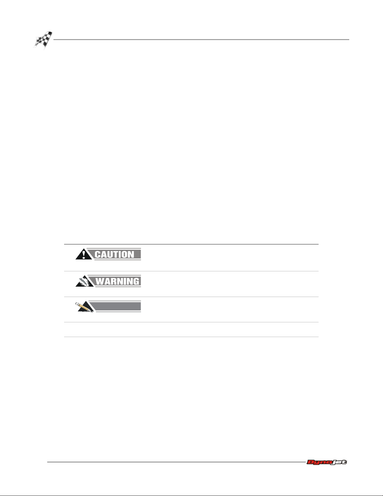
CONVENTIONS USED IN THIS MANUAL
The conventions used in this manual are designed to protect both the user and the
equipment.
example of convention description
The Caution icon indicates a potential hazard to the
dynamometer equipment. Follow all procedures
exactly as they are described and use care when
performing all procedures.
The Warning icon indicates potential harm to the
person performing a procedure and/or the
dynamometer equipment.
The Record # icon reminds you to record your
dynamometer and/or eddy current brake (retarder)
number on the inside cover of this manual.
Bold Highlights items you can select on in the software
interface, including buttons and menus.
The arrow indicates a menu choice. For example,
“select File
then select the Open choice on the File menu.”
Open” means “select the File menu,
TECHNICAL SUPPORT
For assistance, please contact Dynojet Technical Support at 1-800-992-3525, or write
to Dynojet at 2191 Mendenhall Drive, North Las Vegas, NV 89081.
Visit us on the World Wide Web at www.dynojet.com and www.winpep.com where
Dynojet provides state of the art technical support, on-line shopping, 3D
visualizations, and press releases about our latest product lines.
1-2
Model SD12 Scooter Dynamometer Installation Guide
Page 11

YOUR DYNO ROOM
This section is not meant to imply that a dyno room is essential to repeatable results
on a Dynojet dynamometer. However, a dyno room with an engine cooling intake fan,
exhaust extraction, and noise reduction capabilities can add a new dimension to your
shop.
A proper dyno room design will help to ensure repeatable, accurate runs. A good
dyno room should do the following:
• minimize noise
• provide a controlled environment for testing
• provide a view window (safety glass) for customers
• be designed with safety in mind
Intake Air Fan—After building your dyno room, you will need to supply an intake air
fan. The intake air fan supplies air to cool the bike’s engine while supplying fresh
oxygen for you and your bike to breathe. It is a common misconception that you
cannot tune a bike without a large fan simulating exact road conditions; however, a
good cooling fan is the only requirement for consistent diagnostics and tuning. The
installed fan should be 5200 CFM.
SPECIFICATIONS AND OPERATING REQUIREMENTS
Introduction
Equalizer Box—If the air flow rate coming into the dyno room is greater than the air
flow rate leaving the dyno room, the room will become pressurized. A pressurized
dyno room will make measured power misleading. To compensate, you need an
equalizer box. The equalizer box is a baffled (to reduce noise) vent to the outside of
your dyno room. The size of the equalizer box is dependent on the size of your dyno
room and the size of your fans.
Exhaust Extraction—An exhaust fan is needed to remove exhaust gasses, especially
carbon monoxide, from the dyno room. Carbon monoxide is potentially lethal to
people if not removed from the room and will affect engine power when mixed with
fresh air. Plans for exhaust extraction (P/N 73429201) are available from Dynojet.
Engine exhaust contains poisonous carbon monoxide gas. Breathing it could
cause death. Operate machine in well ventilated area.
Fire Suppression—Always have adequate fire suppression or fire extinguishers in
your dyno room.
Industrial Noise Control, Inc.—Industrial Noise Control, Inc. offers a zinc-coated
steel room custom built to your specifications. This room meets all dyno room
requirements. The dyno room must be clean and dry with a comfortable room air
temperature above 32 degrees Fahrenheit (0 degrees Celsius), and have some system
of exhaust extraction. For more information on a dyno room, refer to your
Pre-Installation Guide For Model 200i, 250i, 200iP, and 250iP Motorcycle
Dynamometers (P/N 98129103).
Vers ion 3 Model SD12 Scooter Dynamometer Installation Guide
1-3
Page 12

CHAPTER 1
. . . . . . . . . . . . . . . . . . . . . . . . . . . . . . . . . . .
Dynamometer Specifications and Requirements
DYNAMOMETER SPECIFICATIONS AND REQUIREMENTS
The following specifications and requirements will help you set up your dyno area
and verify you have the requirements to operate your dyno safely.
CHASSIS SPECIFICATIONS
description specifications
Length
dyno 218.70 cm (86.10 in.)
with ramp 335.92 cm (131.25 in.)
Height
to top of dyno 31.00 cm (12.21 in.)
to top of wheel clamp 61.10 cm (24.05 in.)
Width
of dyno 48.21 cm (18.98 in.)
of dyno with tie-downs 86.36 cm (34.00 in.)
Weight
dyno/crated dyno 272 kg (600 pounds)
Drum
diameter 30.50 cm (12.00 in.)
width 35.56 cm (14.00 in.)
Frame structural steel
Maximum Speed 175 KPH (109 MPH)
Maximum Scooter Length (front of front
wheel to center of rear wheel)
Remote Switches remote software control
188.27 cm (74.125 in.)
1-4
Model SD12 Scooter Dynamometer Installation Guide
Page 13

SPECIFICATIONS AND OPERATING REQUIREMENTS
SD001
335.92 cm
(131.25 in)
48.21 cm
(18.98 in)
61.10 cm
(24.05 in)
31.00 cm
(12.21 in)
86.36 cm
(34.00 in)
218.70 cm
(86.10 in)
SD002
Drum Module
Wheel Clamp
Stand Alone
Blowers Option
(not shown)
Air Pump Option
(not shown)
Front Support
Folding Ramp
Tie-Down
Brake Release
Dynamometer Specifications and Requirements
Figure 1-1: Model SD12 Dyno Dimensions
Figure 1-2: Model SD12 Dyno
Vers ion 3 Model SD12 Scooter Dynamometer Installation Guide
1-5
Page 14

CHAPTER 1
Dynamometer Specifications and Requirements
COMPRESSED AIR REQUIREMENTS
The following requirements are needed for optional compressed air pump assembly:
• Clean and dry air, 100 psi or greater, 5 CFM or better flow
• Fittings to hook your air system to a 3/8-inch inside diameter hose (if no air brake is
present)
• optional air regulator
COMPUTER SPECIFICATIONS
You will need to provide a computer system to run the WinPEP software. WinPEP 7
includes complete documentation in online Help. From the WinPEP 7 menu bar,
choose Help
name and password). Refer to the section on Computer Specifications in the WinPEP
documentation, P/N 98118103, for the specific computer system requirements.
WinPEP 7 Help or visit www.winpep.com (accessible with a valid user
ENVIRONMENTAL REQUIREMENTS
description specifications
Te mp e r at u r e
operating min./max 10°C/50°C (50°F/122°F)
storage min./max 0°C/60°C (32°F/140°F)
Humidity 0 to 95% non condensing
FORKLIFT REQUIREMENTS
You will need to provide equipment capable of lifting a minimum of 454 kg.
(1000 lb.) to lift and move the crated dyno.
You will need to provide a 5/8-inch x 3-foot steel bar to lift the drum off the crate.
PHONE AND INTERNET ACCESS
Dynojet recommends you have a phone close to the dyno to call for assistance in an
emergency. You may also wish to contact Dynojet to troubleshoot your dyno.
Internet access on your computer is desirable for contacting Dynojet and
downloading new information and updates.
TIE-DOWN STRAPS
Dynojet recommends using motorcycle tie-down straps for securing the bike on the
dyno. You will need to provide the tie-down straps.
1-6
Model SD12 Scooter Dynamometer Installation Guide
Page 15

. . . . . . . . . . . . . . . . . . . . . . . . . . . . . . . . . . .
DYNO ELECTRONICS
9-pin RS-232 socket
CPU module
atmospheric
sensing module
RPM module
input/output module
9-pin hand
held pendant
3-pin power plug
system expansion
connector
RPM inductive
pickup socket
25-pin socket
power
The standard dyno electronics package is comprised of four interconnected modules:
Atmospheric Sensing Module, RPM Module, Dynamometer Input/Output Module, and
the CPU Module. For more information refer to your WinPEP 7 User Guide
(P/N 98118103).
SPECIFICATIONS AND OPERATING REQUIREMENTS
Dyno Electronics
Figure 1-3: The Dyno Electronics
Vers ion 3 Model SD12 Scooter Dynamometer Installation Guide
1-7
Page 16

Page 17

C HAPTER
2
I
NSTALLATION
This chapter will walk you through unpacking and installing the dynamometer. To
ensure safety and accuracy in the procedures, perform the procedures as they are
described.
This chapter is divided into the following categories:
• Unpacking the Dyno, page 2-2
•Installation, page 2-4
• Fold and Move the Dyno, page 2-10
• Accessories, page 2-13
Model SD12 Scooter Dynamometer Installation Guide
2-1
Page 18

CHAPTER 2
. . . . . . . . . . . . . . . . . . . . . . . . . . . . . . . . . . .
#
RECORD
Unpacking the Dyno
UNPACKING THE DYNO
When you receive your dyno, examine the exterior of the shipping container for any
visible damage. If damage is detected at this stage, contact the shipper or Dynojet
before proceeding with unpacking.
Use the following steps to unload your dyno. You will need to provide equipment
capable of lifting a minimum of 454 kg (1000 pounds) to move the crated dyno into
position in your dyno room. Refer to “Dynamometer Specifications and
Requirements” on page 1-4 for more information.
The following directions describe how to unpack, and install your dyno. Follow the
directions in the order that they are presented.
UNPACKING THE DYNO
1 Move the crated dyno to a clear area near your dyno room.
2 Using a pry bar, or a large flat screwdriver, and a hammer, carefully remove the
top and sides of the crate.
Note: At this point, you will want to inspect the exterior of the dyno for any
indications of damage. Report any damage immediately.
part description part description
Be sure you record the dynamometer number on the inside cover of this
manual.
3 Remove the hardware boxes from the crate.
4 Verify the contents of the hardware boxes and set aside.
drum wheel clamp
P/N 71300003
front support dyno electronics
P/N 76199001
ramp inductive secondary
pickup
P/N DE100-109S
2-2
Model SD12 Scooter Dynamometer Installation Guide
Page 19

INSTALLATION
#
RECORD
SD018
steel bar
shaft hole
Unpacking the Dyno
part description part description
axle shaft (2)
P/N 22100011
inductive primary pickup
clip
P/N DE100-110L
retaining ring, 1/2" (4)
P/N 32800000
screw, 1/4-20 x 5/8”, panhead, torx (2)
P/N 36561045
REMOVING THE DRUM FROM THE CRATE
You will need to provide a 5/8-inch x 3-foot steel bar to lift the drum off the crate and
into position in your dyno room. Lifting the drum will require two people.
Be sure you record the dynamometer number on the inside cover of this
manual.
1 Remove the lag bolts and washers securing the drum to the crate base using a
9/16-inch socket, open or box end wrench.
2 Insert the 5/8-inch x 3-foot steel bar into the shaft hole.
3 Using two people, carefully lift the drum off the crate and move into position in
your dyno room.
cable tie, 4” (2)
P/N 197104130
Figure 2-1: Insert the Steel Bar and Lift the Drum off the Crate
Vers ion 3 Model SD12 Scooter Dynamometer Installation Guide
2-3
Page 20

CHAPTER 2
. . . . . . . . . . . . . . . . . . . . . . . . . . . . . . . . . . .
SD003
drum
front support
Installation
INSTALLATION
Use the following steps to install the scooter dyno.
You will need the following parts:
•Drum
•Front Support
•Ramp
• 197104130 Cable Tie, 4" (2)
• 22100011 Axle Shaft (2)
• 32800000 Retaining Ring, 1/2" (4)
• 36561045 Screw, 1/4-20 x 5/8", Pan-head, Torx (2)
• 71300003 Wheel Clamp
INSTALLING THE FRONT SUPPORT
1 Place the front support on the drum.
Figure 2-2: Place Front Support on the Drum
2-4
Model SD12 Scooter Dynamometer Installation Guide
Page 21

INSTALLATION
SD004
axle shaft
axle shaft
retaining ring
SD007
wheel clamp
spring
plunger
Installation
2 Install the front support axle shaft.
3 Secure the shaft in place using two retaining rings.
Figure 2-3: Install the Axle Shaft and Retaining Rings
4 Slide the wheel clamp onto the front support.
5 Lift the spring plunger to slide the wheel clamp to a different position. Release
the spring plunger to lock the wheel clamp in the new position.
Note: The wheel clamp may already be installed.
Figure 2-4: Install the Wheel Clamp
Vers ion 3 Model SD12 Scooter Dynamometer Installation Guide
2-5
Page 22

CHAPTER 2
SD023
control lever
control cable
control lever
bracket
cable ties
Installation
6 Route the control cable, lever, and control lever bracket from the drum along the
inside of the front support.
Note: The control cable is coiled up and secured to the drum.
7 Secure the control lever bracket to the inside of the front support using two
1/4-20 x 5/8-inch pan-head torx screws.
8 Secure the control cable to the inside of the front support using two cable ties.
Figure 2-5: Install the Control Lever Bracket and Cable
2-6
Model SD12 Scooter Dynamometer Installation Guide
Page 23

ROUTING CABLES
SD032
breakout board
pickup card cable
pickup card
25-pin computer
cable
1 Route the pickup card cable to the Breakout board.
Note: The pickup card is already installed and is located on the drum.
2 Route the 25-pin RS232 computer cable from the Breakout board to the dyno
electronics CPU Module.
3 Route the 9-pin cable from the RS232 port on the dyno electronics to your
computer.
For more information on wiring the Breakout board, refer to “Wiring the
Breakout Board” on page 2-8. For more information on connecting cables to the
dyno electronics, refer to “Dyno Electronics” on page 1-7.
INSTALLATION
Installation
Figure 2-6: Routing Cables
Vers ion 3 Model SD12 Scooter Dynamometer Installation Guide
2-7
Page 24

CHAPTER 2
25-pin computer cable
pickup card
J1J2
digital brake
Installation
WIRING THE BREAKOUT BOARD
1 Attach the pickup card cable to the Breakout board. The pickup card cable has
four wires which connect to the wiring block labeled DRUM 1.
• Red wire connects to R1 • Black wire connects to B1
• White wire connects to W1 • Ground (shield) wire connects to S1
2 Attach the 25-pin RS232 computer cable to the Breakout board.
3 Verify jumpers J1 and J2 are set for the digital brake as shown in Figure 2-7.
2-8
Model SD12 Scooter Dynamometer Installation Guide
Figure 2-7: Wire the Breakout Board
Page 25

INSTALLING THE RAMP
SD008
retaining ring
axle shaft
ramp
axle shaft
1 Place the ramp on the drum.
2 Install the ramp axle shaft.
3 Secure the shaft in place using two retaining rings.
INSTALLATION
Installation
Figure 2-8: Install the Ramp
Vers ion 3 Model SD12 Scooter Dynamometer Installation Guide
2-9
Page 26

CHAPTER 2
. . . . . . . . . . . . . . . . . . . . . . . . . . . . . . . . . . .
SD021
slide wheel clamp to
lock ramp in place
slide wheel
clamp forward
lock front support
in place
raise ramp
Fold and Move the Dyno
FOLD AND MOVE THE DYNO
Use the following instructions to fold and move the scooter dyno.
FOLDING THE DYNO
1 Lift the front support up until it clicks and locks into place.
2 Lift the spring plunger and slide the wheel clamp forward on the front support.
Release the spring plunger to lock the wheel clamp in position.
3 Raise the ramp until it comes in contact with the front support.
4 Lift the spring plunger and slide the wheel clamp until it locks the ramp in place.
Release the spring plunger.
2-10
Model SD12 Scooter Dynamometer Installation Guide
Figure 2-9: Folding the Dyno
Page 27

MOVING THE DYNO
SD020
front support
leg brace
front support
leg brace
1 With the scooter dyno in the folded position, grab the front support leg brace.
2 Tilt the dyno towards you.
3 Roll the dyno to the desired position.
INSTALLATION
Fold and Move the Dyno
Figure 2-10: Moving the Dyno
Vers ion 3 Model SD12 Scooter Dynamometer Installation Guide
2-11
Page 28

CHAPTER 2
SD022
slide wheel
clamp forward
control lever
lower ramp
Fold and Move the Dyno
OPENING THE DYNO
1 Lift the spring plunger and slide the wheel clamp forward. Release the spring
plunger to lock the wheel clamp in position.
2 Lower the ramp to the floor.
3 Squeeze the control lever to release the front support.
4 Lower the front support to the floor.
Figure 2-11: Opening the Dyno
2-12
Model SD12 Scooter Dynamometer Installation Guide
Page 29

. . . . . . . . . . . . . . . . . . . . . . . . . . . . . . . . . . .
ACCESSORIES
This section describes the various optional accessories that are available for the
scooter dyno to meet your individual needs. For more information about these
accessories, please contact Dynojet’s Product Specialists at 1-800-992-3525 for pricing
and availability. Complete installation instruction manuals may also be found by
browsing the Manuals folder on your WinPEP installation CD.
COMPRESSED AIR PUMP ASSEMBLY
INSTALLATION
Accessories
Refer to the Compressed Air Air Fuel Ratio Module Installation and User Guide
(P/N 98200006) for proper operating and maintenance procedures. Refer to the Flow
Meter User Guide (P/N 98129104) to test your air pump for accuracy. Failure to follow
proper procedures may result in inaccurate data or damage to the equipment. These
manuals can be found on your WinPEP CD or at www.dynojet.com.
The sensor and the copper sample tube are hot. Before touching the sensor or
the sample tube, make sure it has cooled.
Leaded racing fuels and two-stroke applications will contaminate the sensor
and dramatically shorten its service life.
The sensor is not covered by a warranty. Be sure to read and understand the
Compressed Air Air Fuel Ratio Module Installation and User manual.
Before turning the pump on, verify there is no water in the hose.
Warm up the vehicle before placing the copper sample tube in the exhaust to
avoid drawing excess water through the pump assembly.
Keep the air pump assembly upright. Tipping the pump assembly may result in
damage to the sensor.
Leaks in the system will result in erroneous readings. Verify there are no cracks
or holes in the hose. Verify the sensor is seated properly in the sensor block.
To ensure accurate readings, pump maintenance should be performed every
six months, or sooner, depending on usage. Refer to the Compressed Air Air
Fuel Ratio Module Installation and User Guide for more information.
STAND ALONE BLOWERS
Refer to the High Pressure Blower Installation Guide (P/N 98220105) for proper
installation and operating procedures. These manuals can be found on your WinPEP
CD or at www.dynojet.com.
Vers ion 3 Model SD12 Scooter Dynamometer Installation Guide
2-13
Page 30

Page 31

B
ASIC
D
YNO
C HAPTER
O
PERATION
3
This chapter includes instructions for basic dyno operation. For more detailed
instructions, refer to the WinPEP 7 User Guide. This manual can be found on your
WinPEP CD or at www.dynojet.com.
This chapter is divided into the following categories:
•Loading the Vehicle, page 3-2
• Connecting the RPM Pickup, page 3-4
•Pre-Run Inspection, page 3-7
• Making a Test Run, page 3-9
• Preventative Maintenance, page 3-10
Model SD12 Scooter Dynamometer Installation Guide
3-1
Page 32

CHAPTER 3
. . . . . . . . . . . . . . . . . . . . . . . . . . . . . . . . . . .
slide the
wheel clamp
center drive axle
on dyno drum
wheel clamp
handle
Loading the Vehicle
LOADING THE VEHICLE
Use the following steps to load a vehicle on the dyno.
Risk of injury. Always wear proper eye and ear protection when operating the
dyno.
1 Verify your computer is running.
2 Verify the wheel clamp is at the front of the front support.
Lift the spring plunger to slide the wheel clamp to a different position. Release
the spring plunger to lock the wheel clamp in the new position.
3 Drive the vehicle onto the dyno and align the vehicle straight with the dyno.
4 Stop the vehicle when the drive axle is centered on the drum.
5 When the vehicle is positioned properly on the dyno, shut the engine off.
• If the vehicle has an automatic transmission, apply the parking brake.
• If the vehicle has a manual transmission, place it in gear.
6 Slide the wheel clamp up to the front tire of the vehicle.
Lift the spring plunger to slide the wheel clamp to a different position. Release
the spring plunger to lock the wheel clamp in the new position.
7 Turn the wheel clamp handle until the front tire is held securely in the wheel
clamp.
Figure 3-1: Load the Vehicle
3-2
Model SD12 Scooter Dynamometer Installation Guide
Page 33

8 Extend the tie-down outriggers.
SD002
tie-down
outrigger
spring pin
8a Remove the spring pins.
8b Slide out the tie-down outriggers.
8c Replace the spring pins.
BASIC DYNO OPERATION
Loading the Vehicle
Figure 3-2: Extend the Tie-Down Outriggers
9 Attach two tie-down straps from the tie-downs on the dyno to the frame or
luggage rack of the vehicle.
10 Tighten the tie-down straps evenly making sure the drive wheel remains centered
on the drum.
Never perform a dyno run if the tie-down straps are not in place or they are
damaged.
Figure 3-3: Attach the Tie-Downs
Vers ion 3 Model SD12 Scooter Dynamometer Installation Guide
3-3
Page 34

CHAPTER 3
. . . . . . . . . . . . . . . . . . . . . . . . . . . . . . . . . . .
Connecting the RPM Pickup
CONNECTING THE RPM PICKUP
Your Dynojet dynamometer includes a primary wire inductive pickup and two
secondary wire inductive pickups. These small “clothespin like” inductive pickups are
used to sense RPM. An RPM pickup is required if you want to view torque graphs.
Generally you will use one secondary wire inductive pickup on a spark plug wire.
Vehicles with wasted spark ignition systems may require two secondary inductive
pickups. On a wasted spark ignition, typically one coil will be connected to two spark
plug wires. Attach one secondary pickup to each of these wires. If the pickups are
connected to two plug wires that do not fire at the same time, an erratic RPM readout
may occur. The primary wire inductive pickup senses RPM pulses from the coil.
Although this pickup location generally works better, it is harder to find the correct
location to connect the RPM pickup.
Note: If a pickup is not being used, disconnect it from the dyno electronics to
prevent any stray pick up of signals.
Inductive pickups are very fragile. The ferrite core can easily be damaged and
is not covered under warranty. Dropping, snapping, vibration, and heat can all
damage the ferrite core.
RPM pickup description
Secondaries (Non- wasted spark system) Use one secondary pickup. Unplug the other pickup from the RPM
Secondaries (Wasted spark ignition
system)
Primary pickup Attach the primary wire pickup to the primary side of the coil. Set
The dyno electronics RPM module contains the electronics that sense the RPM pulses.
An auto-gain circuit looks at only the peak voltage of the vehicle’s spark, ignoring the
lower voltages to help reduce electronic noise problems. Wasted spark ignition
systems will produce a lower voltage level on the exhaust stroke than the
compression stroke. By definition of the auto-gain circuit, lower voltage spark levels
will be ignored, missing every other spark the vehicle would produce.
RPM PICKUP DESCRIPTIONS
module and set the degrees between plug fires to 720° in WinPEP 7.
Use two secondary pickups. Attach one pickup on each spark plug
wire on the same coil and set the degrees between plug fires to 360°
in WinPEP 7.
the degrees between plug fires by taking 720 (four cycle engines) or
360 (two cycle engines) divided by the number of coils. For
example, the number of degrees between plug fires on a four
cylinder four cycle engine with dual coils (where each coil fires two
cylinders) is 720/4 x 2 = 360°.
3-4
Model SD12 Scooter Dynamometer Installation Guide
Page 35

CONNECTING THE SECONDARY INDUCTIVE PICKUP
connect secondary
inductive pickup on
the coil wire
coil
connect secondary inductive
pickup on the coil wires
coil
The secondary inductive pickup cannot be in contact with, or it’s connecting wire be
crossing, other engine electrical wires or stray RF interference may result.
The inductive pickups contain a fragile Ferrite Core that is sensitive to engine
heat and vibration. Do not drop the inductive pickup or snap the pickup
closed. Use extreme care in handling and placement of the pickups.
BASIC DYNO OPERATION
Connecting the RPM Pickup
1 Clip the secondary inductive pickup around one spark plug wire.
Note: On a wasted spark ignition system, two secondary inductive pickup wires
may be needed.
2 Route the inductive pickup cable clear of devices that produce electronic noise
(spark plug wires, coil wire, coil etc.) to the dyno electronics RPM module.
Note: Inductive pickup placement is important. Position the inductive pickup so
that it is not making contact with any other spark plug wires. Separate the spark
plug wire from the spark plug wire bundle for proper operation.
Note: You must ground the vehicle to the dyno for the electronics to function
properly.
Figure 3-4: Connect the Secondary Inductive Pickup
Vers ion 3 Model SD12 Scooter Dynamometer Installation Guide
3-5
Page 36

CHAPTER 3
connect primary
inductive pickup on
the negative side of
the coil
coil
Connecting the RPM Pickup
CONNECTING THE PRIMARY INDUCTIVE PICKUP
The primary inductive pickup cannot be in contact with, or it’s connecting wire be
crossing, other engine electrical wires or stray RF interference may result.
The inductive pickups contain a fragile Ferrite Core that is sensitive to engine
heat and vibration. Do not drop the inductive pickup or snap the pickup
closed. Use extreme care in handling and placement of the pickups.
1 Clip the primary inductive pickup around the wire to the primary side of the coil.
2 Route the primary wire cable clear of devices that produce electronic noise to the
dyno electronics RPM module.
Note: You must ground the vehicle to the dyno for the electronics to function
properly.
3-6
Model SD12 Scooter Dynamometer Installation Guide
Figure 3-5: Connect the Primary Inductive Pickup
Page 37

. . . . . . . . . . . . . . . . . . . . . . . . . . . . . . . . . . .
PRE-RUN INSPECTION
Perform a vehicle inspection before making a run. Check the following:
• Check the radiator coolant (if applicable) and oil levels.
•Check the fuel source.
• Rotate the drum and check for rocks caught in the tire tread that could fly out.
• For scooters equipped with a drive chain, check the chain and the chain master
link. Make sure it is lubricated and adjusted to the proper tension.
• Check the tire pressure and tire speed rating. Improperly inflated tires or
exceeding the maximum speed rating can result in premature wear or severe tire
damage. Make sure the tire has no major deficiencies (cracks in sidewalls, tread life,
etc.).
• Visually inspect the vehicle. Make sure it is in safe running order.
• Make sure ear protection and safety glasses are used when the dyno is being
operated.
• Check the tie-down straps to make sure that they are tight and secured.
BASIC DYNO OPERATION
Pre-Run Inspection
• Check the drive tires to be sure that they are aligned correctly on the
dynamometer’s drums.
• Keep all rotating components clear at all times.
• Only the operator should be near the dyno or the vehicle during the test.
• Never allow any person(s) to stand behind the dyno or vehicle when it is being
operated.
• Perform any other safety inspections appropriate to running your vehicle on the
dyno.
Never allow any person(s) to stand behind the dyno or vehicle when it is being
operated. Only the operator should be near the dyno or the vehicle during the
test.
Vers ion 3 Model SD12 Scooter Dynamometer Installation Guide
3-7
Page 38

CHAPTER 3
Pre-Run Inspection
BEFORE STARTING THE ENGINE
Connect an exhaust hose or hoses (if dual exhaust) on the vehicle, make sure the
hose fits over the tail pipe, is not plugged or kinked and the hose is vented correctly
out of the dyno room.
Engine exhaust contains poisonous carbon monoxide gas. Breathing it could
cause death. Operate machine in well ventilated area.
ENGINE WARM UP
Warm the vehicle’s engine and drivetrain before beginning testing. Consistent engine
temperatures will assure your runs are repeatable.
AFTER ENGINE WARM UP
Always leave the vehicle in neutral (automatic transmission) or in first gear (manual
transmission), with the engine off, and make sure the park brake and the dyno brake
are on when you get off the vehicle on the dyno.
• Fix any fuel, oil, or coolant leaks that may have shown up after engine warm up and
check the carburetor for leaks.
• Any loud or unusual engine noises or excessive exhaust smoke should be resolved
before continuing.
3-8
Model SD12 Scooter Dynamometer Installation Guide
Page 39

. . . . . . . . . . . . . . . . . . . . . . . . . . . . . . . . . . .
MAKING A TEST RUN
Dyno runs provide safe, reliable road testing right in the shop. The dyno allows you to
measure, record, and diagnose performance problems quickly. The dyno combined
with WinPEP 7 produces consistent, easily interpretable power graphs. Use the
following instructions to ensure repeatable and accurate measurements.
1 Verify the vehicle is secured properly.
2 Release the dyno brake by pressing the brake pedal.
3 Slowly accelerate the vehicle to 20 m.p.h.
4 Test the tachometer operation.
4a Rev the engine. The gauges on the computer screen should be moving. If
the tachometer is moving but not registering the correct RPM values, the
number of degrees of revolution of the crank shaft (the plug fires number) is
incorrect.
4b Stop the vehicle, return to the MakeRun Configuration dialog box, and enter
the correct value for the plug firing order.
5 Step off the brake pedal to apply 100% braking and slow down the vehicle.
BASIC DYNO OPERATION
Making a Test Run
Using the vehicle’s own brakes to slow or stop the drum at speeds over 30
m.p.h. can severely over heat the brake parts. The vehicle’s brakes should be
used in an emergency stop situation only.
6 Shut the engine off and put the vehicle in gear (manual transmission) or apply the
parking brake (automatic transmission).
7 Set the vehicle’s parking brake and leave the dyno brake on.
8 Perform a final inspection.
• Verify the drive tire’s alignment on the dyno drums.
• Make any adjustments to the tie-down straps as needed.
• Perform any other safety checks that you deem appropriate to your particular
situation.
You are now ready to make a high speed run on the dyno. Refer to your WinPep 7
User Guide for more detailed instructions.
Vers ion 3 Model SD12 Scooter Dynamometer Installation Guide
3-9
Page 40

CHAPTER 3
. . . . . . . . . . . . . . . . . . . . . . . . . . . . . . . . . . .
SD024
brake stop bolt
Preventative Maintenance
PREVENTATIVE MAINTENANCE
This section contains basic preventative maintenance and troubleshooting
information.
To maintain proper dynamometer operation, Dynojet recommends you make routine
checks of the dyno.
• Drum—keep the drum clean and keep all objects clear of the drum.
• Carriage Slide—keep the carriage slide clean and lightly lubricated.
ADJUSTING THE BRAKE
Use the following instructions to prevent the brake from dragging.
1 Remove any vehicles from the dyno.
2 Push the brake pedal until it stops.
3 Using your hand, turn the drum.
4 Verify the brake is not dragging.
5 If the brake is dragging, adjust the brake.
Using a 7/16 open end wrench, adjust the brake stop bolt until there is no brake
drag.
Note: Adjusting the bolt too loose or too tight can cause brake drag.
Figure 3-6: Adjust the Brake
3-10
Model SD12 Scooter Dynamometer Installation Guide
Page 41

ADJUSTING THE BRAKE TENSION
eyebolt
adjust brake tension here
brake release pedal
Use the following instructions to adjust the brake tension.
1 Locate the eyebolt brake tension adjuster.
2 With the brake release pedal in the up position, turn the 1/4-20 nut on the eyebolt
clockwise to increase the spring tension until the drum can no longer be turned
by hand.
3 Verify the brake releases when the pedal is fully depressed.
Note: The eyebolt can be adjusted until it touches the lever on the release shaft
mechanism. If the eyebolt makes contact when the brake release pedal is fully
depressed, then the eyebolt has been adjusted too far. Back off the eyebolt nut
until it no longer contacts the lever.
BASIC DYNO OPERATION
Preventative Maintenance
Figure 3-7: Adjust the Brake Tension
Vers ion 3 Model SD12 Scooter Dynamometer Installation Guide
3-11
Page 42

Page 43

I
NDEX
A
accessories 1-5
compressed air pump 2-13
stand alone blowers 2-13
air pump assembly 2-13
axle shaft 2-5
B
battery hazards iv
blowers 2-13
brake tension, adjusting 3-11
brake, adjusting 3-10
breakout board
jumpers 2-8
pickup card 2-8
C
cables
pickup card 2-8
RS232 2-8
chassis specifications 1-4
height 1-4
length 1-4
weight 1-4
width 1-4
compressed air 1-6
compressed air pump 2-13
computer specifications 1-6
control cable 2-6
conventions 1-2
CPU module 2-7
crate
remove dyno 2-3
D
dimensions 1-5
disclaimers iii
document part number 1-1
dyno
contents 2-2
height 1-4
installing 2-2
length 1-4
unpacking 2-2
weight 1-4
width 1-4
dyno electronics 1-7
dyno room 1-3
equalizer box 1-3
exhaust extraction 1-3
fire suppression 1-3
intake air fan 1-3
noise control 1-3
E
electrostatic discharge iv
environmental requirements 1-6
equalizer box 1-3
ESD precautions iv
exhaust extraction 1-3
eyebolt 3-11
F
fire suppression 1-3
folding the dyno 2-10
forklift requirements 1-6
front support
axle shaft 2-5
control cable 2-6
installing 2-4
wheel clamp 2-5
Model SD12 Scooter Dynamometer Installation Guide
Index-i
Page 44

INDEX
H
hazards v
height 1-4
I
Industrial Noise Control, Inc. 1-3
inspection 3-7
intake air fan 1-3
J
jumpers 2-8
L
length 1-4
lifting bar 1-6, 2-3
loading the vehicle 3-2
M
maintenance 3-10
making a run 3-9
moving the dyno 2-11
O
opening the dyno 2-12
P
phone, internet access 1-6
pickup card
wiring to breakout board 2-8
pickup card cable 2-7
pre-run inspection 3-7
preventative maintenance 3-10
primary inductive pickup 3-6
S
secondary inductive pickup 3-5
specifications 1-4
stand alone blowers 2-13
T
technical support 1-2
testing
dyno, test run 3-9
tie-down straps 1-6, 3-3
U
unpacking dyno 2-2
using the dyno 3-9
W
warnings iii
weight 1-4
wheel clamp 2-5
width 1-4
wiring breakout board
jumpers 2-8
pickup card cable 2-8
Y
your dyno room 1-3
equalizer box 1-3
exhaust extraction 1-3
fire suppression 1-3
intake air fan 1-3
noise control 1-3
R
ramp 2-9
requirements 1-4
chassis specifications 1-4
compressed air 1-6
computer specifications 1-6
environmental 1-6
forklift 1-6
phone, internet access 1-6
tie-down straps 1-6
routing cables
pickup card 2-7, 2-8
RS232 2-7, 2-8
RPM pickup
connecting 3-4
primary inductive pickup 3-6
secondary inductive pickup 3-5
RS232 cable 2-7
Index-ii
Model SD12 Scooter Dynamometer Installation Guide
 Loading...