

Page 1
Page 2

©2002-2004 Dynojet Research, Inc. All Rights Reserved.
Proportional Air Brake Installation Guide.
This manual is copyrighted by Dynojet Research, Inc., hereafter referred to as Dynojet,
and all rights are reserved. This manual is furnished under license and may only be used
or copied in accordance with the terms of such license. This manual is furnished for
informational use only, is subject to change without notice, and should not be construed
as a commitment by Dynojet. Dynojet assumes no responsibility or liability for any error
or inaccuracies that may appear in this manual. Except as permitted by such license, no
part of this manual may be reproduced, stored in a retrieval system, or transmitted, in any
form or by any means, electronic, mechanical, recording, or otherwise, without the prior
written permission of Dynojet.
The Dynojet logo is a trademark of Dynojet Research, Inc.
Any trademarks, trade names, service marks, or service names owned or registered by any
other company and used in this guide are the property of their respective companies.
Dynojet Research, Inc., 2191 Mendenhall Drive, North Las Vegas, Nevada 89031, USA.
Printed in USA.
Part Number: 98212103 Version 4 (07/2004)
Page 3
T
ABLE OF
C
ONTENTS
Proportional Air Brake Installation
Conventions Used In This Manual . . . . . . . . . . . . . . . . . . . . . . . . . . . . . . . . . 1
Technical Support . . . . . . . . . . . . . . . . . . . . . . . . . . . . . . . . . . . . . . . . . . . . . . 1
Installation . . . . . . . . . . . . . . . . . . . . . . . . . . . . . . . . . . . . . . . . . . . . . . . . . . . . 2
Parts List . . . . . . . . . . . . . . . . . . . . . . . . . . . . . . . . . . . . . . . . . . . . . . . . . . . 2
Removing the Standard Air Brake System . . . . . . . . . . . . . . . . . . . . . . . . . . . 3
Installing the Proportional Air Brake System . . . . . . . . . . . . . . . . . . . . . . . . . 4
Wiring the Breakout Board . . . . . . . . . . . . . . . . . . . . . . . . . . . . . . . . . . . . . . 7
Wiring—Four Wheel Drive . . . . . . . . . . . . . . . . . . . . . . . . . . . . . . . . . . . . . . . 9
Wiring the EPR . . . . . . . . . . . . . . . . . . . . . . . . . . . . . . . . . . . . . . . . . . . . . . . 9
Wiring the Breakout Board . . . . . . . . . . . . . . . . . . . . . . . . . . . . . . . . . . . . . 10
Appendix A Replacing the EPR with the Model T-3000 EPR
Replacing the EPR . . . . . . . . . . . . . . . . . . . . . . . . . . . . . . . . . . . . . . . . . . . . .A-2
Wiring the EPR . . . . . . . . . . . . . . . . . . . . . . . . . . . . . . . . . . . . . . . . . . . . . . . .A-6
Proportional Air Brake Installation Guide
i
Page 4

Page 5
P
ROPORTIONAL
AIR B
RAKE INSTALLATION
This document provides instructions for installing the proportional air (prop air)
brake system with the model T-3000 electronic pressure regulator (EPR) to the model
248 automotive dynamometer (dyno). Appendix A includes instructions for replacing
and wiring the old EPR with the model T-3000 EPR. To ensure safety and accuracy in
the procedures, perform the procedures as they are described.
This manual will walk you through removing the standard air brake system and
installing the optional proportional air brake system.
Document Part Number: 98212103
Version 4
Last Updated: 07-16-04
CONVENTIONS USED IN THIS MANUAL
The conventions used in this manual are designed to protect both the user and the
equipment.
example of convention description
The Caution icon indicates a potential hazard to the
dynamometer equipment. Follow all procedures
exactly as they are described and use care when
performing all procedures.
The Warning icon indicates potential harm to the
person performing a procedure and/or the
dynamometer equipment.
TECHNICAL SUPPORT
For assistance, please contact Dynojet Technical Support at 1-800-992-3525, or write
to Dynojet at 2191 Mendenhall Drive, North Las Vegas, NV 89081.
Visit us on the World Wide Web at www.dynojet.com where Dynojet provides state of
the art technical support, on-line shopping, 3D visualizations, and press releases
about our latest product line.
Proportional Air Brake Installation Guide
1
Page 6
PROPORTIONAL AIR BRAKE
Installation
INSTALLATION
. . . . . . . . . . . . . . . . . . . . . . . . . . . . . . . . . . .
This section describes the procedures to remove the standard air brake system, install
the proportional air brake system, and wire the Breakout board.
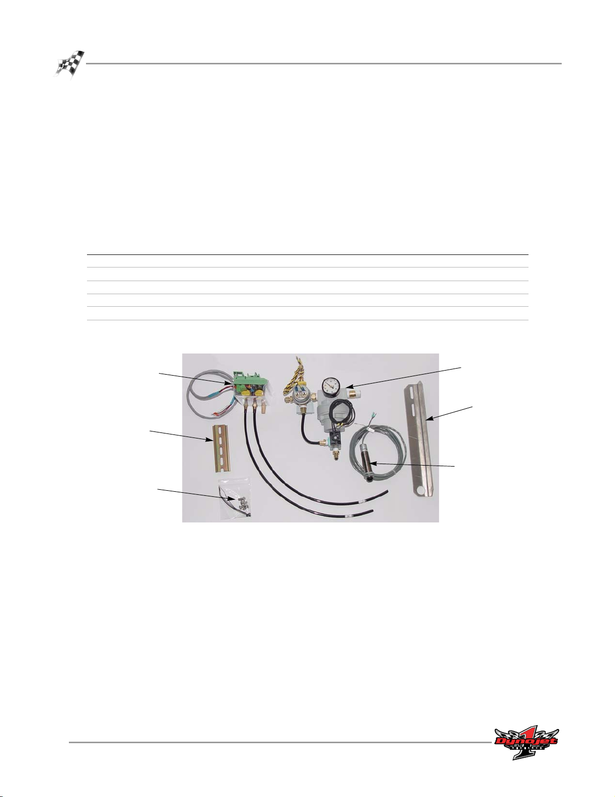
PARTS LIST
The following table lists all of the parts included in the Proportional Air Brake
Installation kit. Check your kit against the parts listed to make sure you have received
all of the parts. If any part is missing, contact Dynojet Technical Support.
part number description quantity
21619200 Temperature Sensor Bracket 1
31614100 DIN Rail 1
36560834 Screw, 1/4"-20 x 1/2", Button-head 4
44997101 Temperature Sensor 1
64111001 Prop Air Regulator Sub Assembly 1
64111002 Control Valve Sub Assembly (electronic pressure regulator, EPR) 1
control valve
assembly (EPR)
prop air regulator
assembly
temperature sensor
bracket
DIN rail
temperature sensor
screws
Figure 1: Proportional Air Brake Components
2
Proportional Air Brake Installation Guide
Page 7
REMOVING THE STANDARD AIR BRAKE SYSTEM
1 Turn off the power on the dyno electronics.
2 Shut off and release the air pressure to the air pressure regulator.
3 Remove the two black wires from the wiring block labeled BRAKE on the
Breakout board.
4 Remove the yellow and black wires from the wiring block labeled PRESS on the
Breakout board.
5 Disconnect the 3/8-inch air hose from the fitting on the air brake control switch.
The air brake control switch is located on top of the right side air canister.
Note: Leave the air hose with the dyno as it will be used later.
6 Unscrew and remove the air brake control switch.
INSTALLATION GUIDE
Installation
air hose
air brake
control switch
Figure 2: Remove the Standard Air Brake
press
brake
Vers ion 4 Proportional Air Brake Installation Guide
3
Page 8

PROPORTIONAL AIR BRAKE
Installation
INSTALLING THE PROPORTIONAL AIR BRAKE SYSTEM
1 Install the DIN rail.
1a Clamp the DIN rail to the right post 14-inches down from the top of the
dyno frame.
1b Using a center punch, mark two mounting holes in the middle of the top
and bottom slots. Remove the clamp and rail.
1c Drill and tap the mounting holes for 1/4-inch UNC bolts.
1d Secure the DIN rail to the dyno using two 1/4-inch button-head allen bolts.
2 Hook one side of the EPR on the DIN rail then rotate it toward the DIN rail until it
snaps into place.
top of dyno
frame
post
DIN rail
install the DIN rail
14 in.
EPR
install the EPR
4
Proportional Air Brake Installation Guide
Figure 3: Install the DIN Rail and EPR
Page 9

top of dyno
frame
post
bracket
INSTALLATION GUIDE
Installation
3 Install the temperature sensor.
3a Clamp the temperature sensor bracket to the left post 24-inches down from
the top of the dyno frame.
3b Using a center punch, mark the bracket mounting holes in the middle of
both slots. Remove the clamp and bracket.
3c Drill and tap the mounting holes for 1/4-inch UNC bolts.
3d Loosely attach the bracket to the dyno using two 1/4-inch button-head allen
bolts. Do not tighten the bolts.
3e Install the temperature sensor so it is approximately three inches from the
surface of the drum.
3f Adjust the bracket so the temperature sensor is aimed at the interface of the
knurl and brake surface. Tighten the bolts to secure the bracket.
4 Screw the prop air regulator assembly into the right side brake canister. Tighten it
so the air gauge is facing out.
drum
sensor
24 in.
prop air regulator
install bracket
Figure 4: Install the Temperature Sensor and Prop Air Regulator Assembly
Vers ion 4 Proportional Air Brake Installation Guide
install sensor
install prop air
regulator assembly
assembly
air canister
5
Page 10

PROPORTIONAL AIR BRAKE
Installation
5 Attach the air line labeled OUT from the EPR to the three-way valve on the prop
air regulator assembly. Push the hose in and hand tighten the fitting.
6 Attach the air line labeled IN from the EPR to the brass four-way fitting on the
prop air regulator assembly.
Note: Pull on both hoses to ensure they are secure. If there is movement, tighten
the fitting.
7 Connect your shop air to the dyno.
Dynojet recommends using an air filter/dryer. Failure to use clean, dry air will
compromise the integrity and life of the air components.
7a Mount the air pressure regulator on the wall in your shop with the bracket
provided.
7b Connect a supply air hose to the inlet of the regulator from your shop air
supply and a 3/8-inch air hose to the outlet side. The regulator should be set
to 60 psi.
7c Connect the 3/8-inch air hose coming from the air pressure regulator to the
barbed inlet fitting on the prop air regulator assembly.
Note: Make sure the arrow on the regulator is the same as the direction of the air
flow.
EPR air line out
attaches to
three-way valve
in
out
EPR air line in
attaches to brass
four-way fitting
regulated air
6
Proportional Air Brake Installation Guide
Figure 5: Routing Cables—Air Lines
Page 11

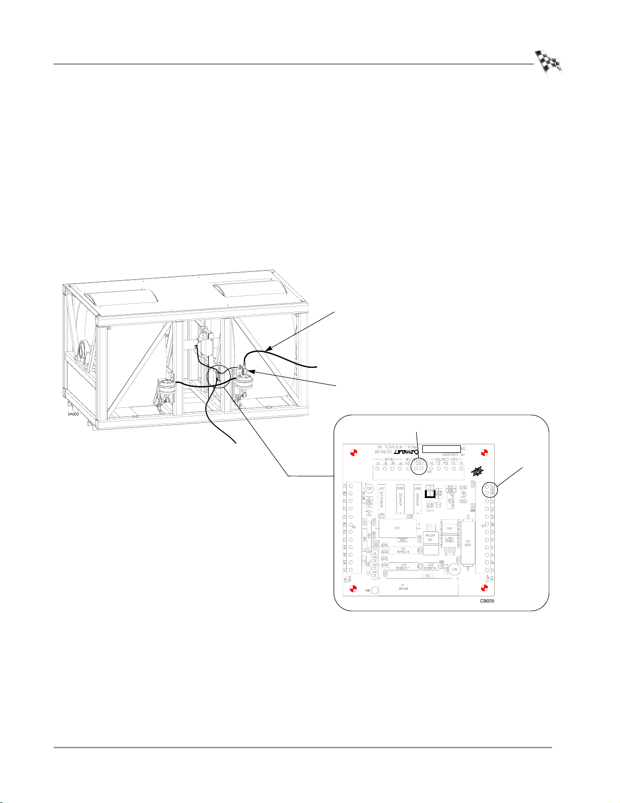
WIRING THE BREAKOUT BOARD
When attaching cables, refer to Figure 6 for cable location and Figure 7 for Breakout
board wiring information. Refer to page 9 for four wheel drive wiring instructions.
1 Attach the data acquisition cable coming from the optical pickup card on the dyno
to the Breakout board. The data acquisition cable has four wires which connect to
the wiring block labeled DRUM 1.
• Red wire connects to R1 • White wire connects to W1
• Black wire connects to B1 • Silver wire connects to S1
2 Attach the wires from the air pressure switch, located on the prop air regulator
assembly, to the wiring block labeled PRESS on the Breakout board. Each wire
may attach in either position.
3 Attach the cable coming from the EPR to the Breakout board. The EPR cable has
four wires which connect to the wiring block labeled LOAD CONTROL.
• Black wire connects to V- • Red wire connects to V+
• White wire connects to O+ • Silver or ground (shield)
INSTALLATION GUIDE
Installation
wire connects to SH
Refer to page 10 when wiring the Breakout board for four wheel drive
applications.
Note: If your EPR is not wired, refer to page A-6 for wiring instructions.
4 Attach the brake wires from the brake solenoid, located on the prop air regulator
assembly, to the wiring block labeled BRAKE on the Breakout board. Each wire
may attach in either position.
5 Attach the temperature sensor cable to the Breakout board. The temperature
sensor cable has five wires which connect to the wiring block labeled TEMP on
the Breakout board.
• Green wire connects to G1 • White wire connects to W1
• Black wire connects to B1 • Red wire connects to R1
• Silver or ground (shield) wire connects to S1
Vers ion 4 Proportional Air Brake Installation Guide
7
Page 12

PROPORTIONAL AIR BRAKE
Installation
temperature
sensor cable
Figure 6: Routing Cables—Breakout Board
data acquisition
cable
EPR cable
air pressure
switch wire
brake solenoid
wires
6 The Breakout board jumper settings are preset, however, verify jumpers J1 and J2
are set for the proportional air brake as shown in Figure 7.
press
load control
drum 1
DynoWare
cable
8
Proportional Air Brake Installation Guide
brake
jumpers
J1 and J2
prop air brake
jumper settings
temp
Figure 7: Prop Air—Wiring the Breakout Board
Page 13

INSTALLATION GUIDE
WIRING—FOUR WHEEL DRIVE
. . . . . . . . . . . . . . . . . . . . . . . . . . . . . . . . . . .
This section provides instructions for wiring the electronic pressure regulator (EPR)
and Breakout board for four wheel drive applications.
WIRING THE EPR
Attach the four wires from the EPR cable to the new EPR.
• Orange wire connects to V+ • White wire connects to SIG
• Blue and green wire connects to CMN
EPR cable
Wiring—Four Wheel Drive
white
SIG
blue and
green
muffler
air output
air input
Figure 8: Four Wheel Drive—Wiring the EPR
orange
V+
CMN
Vers ion 4 Proportional Air Brake Installation Guide
9
Page 14

PROPORTIONAL AIR BRAKE
Wiring—Four Wheel Drive
WIRING THE BREAKOUT BOARD
1 Attach the cable coming from the EPR to the Breakout board. The EPR cable wires
connect to the wiring block labeled LOAD CONTROL.
• Blue wire connects to V- • Orange wire connects to V+
• White wire connects to O+ • Green wire connects to O-
2 The Breakout board jumper settings are preset, however, verify jumpers J1 and J2
are set for the four wheel drive proportional air brake as shown in Figure 9.
load control
jumpers
J1 and J2
four wheel drive
prop air brake
jumper settings
Figure 9: Four Wheel Drive—Wiring the Breakout Board
10
Proportional Air Brake Installation Guide
Page 15

A PPENDIX
R
EPLACING THE
M
ODEL
This appendix provides instructions for replacing the existing electronic pressure
regulator (EPR) with the model T-3000 EPR. To ensure safety and accuracy in the
procedures, perform the procedures as they are described.
EPR
WITH THE
T-3000 EPR
A
Proportional Air Brake Installation Guide
A-1
Page 16

APPENDIXA
Replacing the EPR
REPLACING THE EPR
. . . . . . . . . . . . . . . . . . . . . . . . . . . . . . . . . . .
This section describes how to transfer over to and wire the new EPR.
1 Turn off the power on the dyno electronics.
2 Disconnect the main air supply from the brake assembly.
air supply
A-2
Proportional Air Brake Installation Guide
Figure A-1: Disconnect the Main Air Supply
Page 17

3 Remove the two air lines and the muffler from the old EPR.
4 Transfer the air lines and the muffler to the new EPR.
5 Remove the old EPR cable from the Breakout board and discard.
remove EPR cable from
Breakout board
REPLACING THE EPR WITH THE MODEL T-3000 EPR
Replacing the EPR
Note: If the labels marking the air input and air output are no longer on the two
air lines, re-label the lines. Left is input and middle is output.
Holding the new EPR in the same orientation as the old one (controls at the
bottom), the air lines and muffler hookup the same. Left is air input, middle is air
output, and right is the muffler.
Note: You may need to reapply thread tape to the threads to insure an air tight
connection.
The new EPR comes pre wired at the EPR terminal. You will need to connect this
new cable to the Breakout board.
old ERP
air output
air input
new EPR
Figure A-2: Attach Air Lines to New EPR
air input
muffler
air output
Vers ion 4 Proportional Air Brake Installation Guide
A-3
Page 18

APPENDIXA
Replacing the EPR
6 Attach the cable coming from the new EPR to the Breakout board. The EPR cable
has four wires which connect to the wiring block labeled LOAD CONTROL.
• Black wire connects to V- • Red wire connects to V+
• White wire connects to O+ • Silver or ground (shield)
wire connects to SH
Refer to page 10 when wiring the Breakout board for four wheel drive
applications.
7 The Breakout board jumper settings are preset, however, verify jumpers J1 and J2
are set for the proportional air brake as shown in Figure A-3.
load control
jumpers
J1 and J2
prop air brake
jumper settings
Figure A-3: New EPR—Wiring the Breakout Board
A-4
Proportional Air Brake Installation Guide
Page 19

REPLACING THE EPR WITH THE MODEL T-3000 EPR
Replacing the EPR
8 Rotate the old EPR until it pops off the DIN rail.
9 Hook one side of the new EPR on the DIN rail and rotate it toward the DIN rail
until it snaps into place.
10 Connect the main air supply to the brake assembly. The air will set the brakes.
11 Turn on the power to the dyno electronics. This will release the brakes.
air supply
Figure A-4: Connect the Air Supply
Vers ion 4 Proportional Air Brake Installation Guide
A-5
Page 20

APPENDIXA
Wiring the EPR
WIRING THE EPR
. . . . . . . . . . . . . . . . . . . . . . . . . . . . . . . . . . .
Refer to these wiring instructions only if your EPR is not pre wired.
If your EPR is not wired, attach the wires from the EPR cable to the new EPR.
• Red wire connects to V+ • White (or clear) wire connects to SIG
• Black wire connects to CMN • Silver wire (if present) remains
disconnected
EPR cable
white
SIG
black
Figure A-5: Wiring the New EPR
red
V+
CMN
A-6
Proportional Air Brake Installation Guide
Page 21

 Loading...