

Page 1

PARTS LIST
1 Power Commander
1 USB Cable
2008-2011 Kawasaki VN2000
Installation Instructions
1 Installation Guide
2 Power Commander Decals
2 Dynojet Decals
2 Velcro strips
1 Alcohol swab
THE IGNITION MUST BE TURNED
OFF BEFORE INSTALLATION!
THE LATEST POWER COMMANDER
SOFTWARE AND MAP FILES CAN BE
DOWNLOADED FROM OUR WEB SITE AT:
www.powercommander.com
PLEASE READ ALL DIRECTIONS BEFORE STARTING INSTALLATION
2191 Mendenhall Drive North Las Vegas, NV 89081 (800) 992-4993 www.powercommander.com
17-011 www.powercommander.com 2008-2011 Kawasaki VN2000 - PCV - 1
Page 2
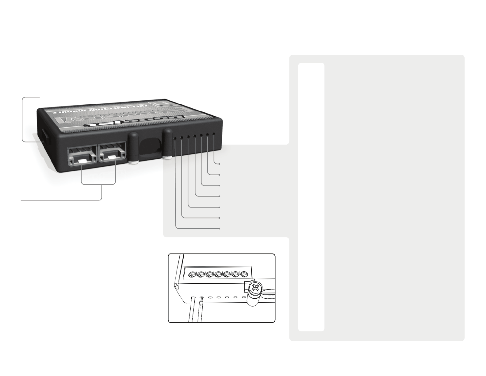
POWER COMMANDER V
INPUT ACCESSORY GUIDE
USB CONNECTION
CRANK
ANALOG
SPEED
ACCESSORY INPUTS
Map - (Input 1 or 2) The PCV has the ability to hold
2 different base maps. You can switch on the
fly between these two base maps when you
hook up a switch to the MAP inputs. You can
use any open/close type switch. The polarity
of the wires is not important. When using the
Autotune kit one position will hold a base map
and the other position will let you activate the
learning mode. When the switch is “CLOSED”
Autotune will be activated. (Set to Switch
Input #1 by default.)
Shifter- (Input 1 or 2) These inputs are for use with the
Dynojet quickshifter. Insert the wires from the
Dynojet quickshifter into the SHIFTER inputs.
The polarity of the wires is not important. (Set
to Switch Input #2 by default.)
EXPANSION PORTS 1 & 2
Optional Accessories such as
POD-300 unit or Auto-tune kit.
Wire connections:
To input wires into the PCV first remove the rubber
plug on the backside of the unit and loosen the
screw for the corresponding input. Using a 22-24
gauge wire strip about 10mm from its end. Push the
wire into the hole of the PCV until is stops and then
tighten the screw. Make sure to reinstall the rubber
plug.
NOTE: If you tin the wires with solder it will make
inserting them easier.
INPUT 2 (Grnd)
INPUT 2
INPUT 1 (Grnd)
INPUT 1
Speed- If your application has a speed sensor then
you can tap into the signal side of the sensor
and run a wire into this input. This will allow
you to calculate gear position in the Control
Center Software. Once gear position is setup
you can alter your map based on gear position
and setup gear dependent kill times when
using a quickshifter.
Analog- This input is for a 0-5v signal such as
engine temp, boost, etc. Once this input
is established you can alter your fuel curve
based on this input in the control center
software.
Crank- Do NOT connect anything to this port unless
instructed to do so by Dynojet. It is used to
transfer crank trigger data from one module to
another.
17-011 www.powercommander.com 2008-2011 Kawasaki VN2000 - PCV - 2
Page 3

FIG.A
1 Remove the main seat and the passenger seat.
2 Remove the chrome left hand side engine cover below the fuel tank.
3 Remove the fuel tank.
FIG.B
PCV harness
FIG.C
Unplug
Unplug
Unplug
To disconnect the fuel line, squeeze the orange tabs while pushing in.
4 Unplug the stock electrical connectors that are located behind the chrome
engine cover that was removed in step 2 (Fig. A).
5 Lay the PCV in the battery area and route the PCV wiring harness forward
towards the throttle bodies following along the stock wiring harness and
through the stock wiring harness guides (Fig. B).
6 Secure the PCV ground wire with the small ring lug to the stock common
ground near the right side of the seat bracket (Fig. C).
Ground
17-011 www.powercommander.com 2008-2011 Kawasaki VN2000 - PCV - 3
Page 4

FIG.D
FIG.E
Unplug
Unplug
Unplug
7 Locate the bike’s throttle body between the cylinders; and unplug both of the
Fuel Injectors.
8 Also, unplug the stock Throttle Position Sensor connectors (Fig. D).
The TPS connectors are the pair of GREY 3-pin connectors.
9 Plug the PCV wiring harness in-line of the Fuel Injectors and the stock wiring
harness (Fig. E).
The pair of PCV leads with ORANGE colored wires go in-line of the front
cylinder fuel injector and stock connector.
Likewise, the pair of PCV leads with YELLOW colored wires go in-line of the
rear cylinder fuel injector and stock connector.
10 Plug the pair of PCV leads with 3-pin connectors in-line of the stock TPS
connectors.
11 Using the supplied Velcro strips, secure the PCV module to the battery cover
FIG.F
17-011 www.powercommander.com 2008-2011 Kawasaki VN2000 - PCV - 4
towards the rear of the shock.
Use the supplied alcohol swab to clean both surfaces prior to applying the
Velcro adhesive.
12 Reconnect the stock electrical connections that were disconnected in step 4.
Reinstall the fuel tank, cover, and seat.
Optional inputs:
Speed - PINK wire of the 3-pin connector located under the right hand side
cover
12v source for Auto-tune - RED wire of the 6-pin tail light connector
 Loading...