

Page 1

18-023 www.powercommander.com 17-18 RC/Duke 390 - PCV - 1
Installation Instructions
PLEASE READ ALL DIRECTIONS BEFORE STARTING INSTALLATION
THE IGNITION MUST BE TURNED
OFF BEFORE INSTALLATION!
THE LATEST POWER COMMANDER
SOFTWARE AND MAP FILES CAN BE
DOWNLOADED FROM OUR WEB SITE AT:
www.powercommander.com
2191 Mendenhall Drive North Las Vegas, NV 89081 (800) 992-4993 www.powercommander.com
PARTS LIST
1 Power Commander
1 USB Cable
1 Installation Guide
2 Power Commander Decals
2 Dynojet Decals
2 Velcro strips
1 Alcohol swab
2 Zip ties
2017-2018 KTM 390 Duke
2017-2018 KTM RC390
Page 2

18-023 www.powercommander.com 17-18 RC/Duke 390 - PCV - 2
EXPANSION PORTS 1 & 2
Optional Accessories such as
POD-300 unit or Auto-tune kit
POWER COMMANDER V
INPUT ACCESSORY GUIDE
Map - (Input 1 or 2) The PCV has the ability to hold
2 different base maps. You can switch on the
fly between these two base maps when you
hook up a switch to the MAP inputs. You can
use any open/close type switch. The polarity
of the wires is not important. When using the
Autotune kit one position will hold a base map
and the other position will let you activate the
learning mode. When the switch is “CLOSED”
Autotune will be activated. (Set to Switch
Input #1 by default.)
Shifter- (Input 1 or 2) These inputs are for use with the
Dynojet quickshifter. Insert the wires from the
Dynojet quickshifter into the SHIFTER inputs.
The polarity of the wires is not important. (Set
to Switch Input #2 by default.)
Speed- If your application has a speed sensor then
you can tap into the signal side of the sensor
and run a wire into this input. This will allow
you to calculate gear position in the Control
Center Software. Once gear position is setup
you can alter your map based on gear position
and setup gear dependent kill times when
using a quickshifter.
Analog- This input is for a 0-5v signal such as
engine temp, boost, etc. Once this input
is established you can alter your fuel curve
based on this input in the control center
software.
Crank- Do NOT connect anything to this port unless
instructed to do so by Dynojet. It is used to
transfer crank trigger data from one module to
another.
ACCESSORY INPUTS
Wire connections:
To input wires into the PCV first remove the rubber
plug on the backside of the unit and loosen the
screw for the corresponding input. Using a 22-24
gauge wire strip about 10mm from its end. Push the
wire into the hole of the PCV until is stops and then
tighten the screw. Make sure to reinstall the rubber
plug.
NOTE: If you tin the wires with solder it will make
inserting them easier.
CRANK
ANALOG
SPEED
INPUT 1 (Grnd)
INPUT 1
INPUT 2 (Grnd)
INPUT 2
USB CONNECTION
Page 3
18-023 www.powercommander.com 17-18 RC/Duke 390 - PCV - 3
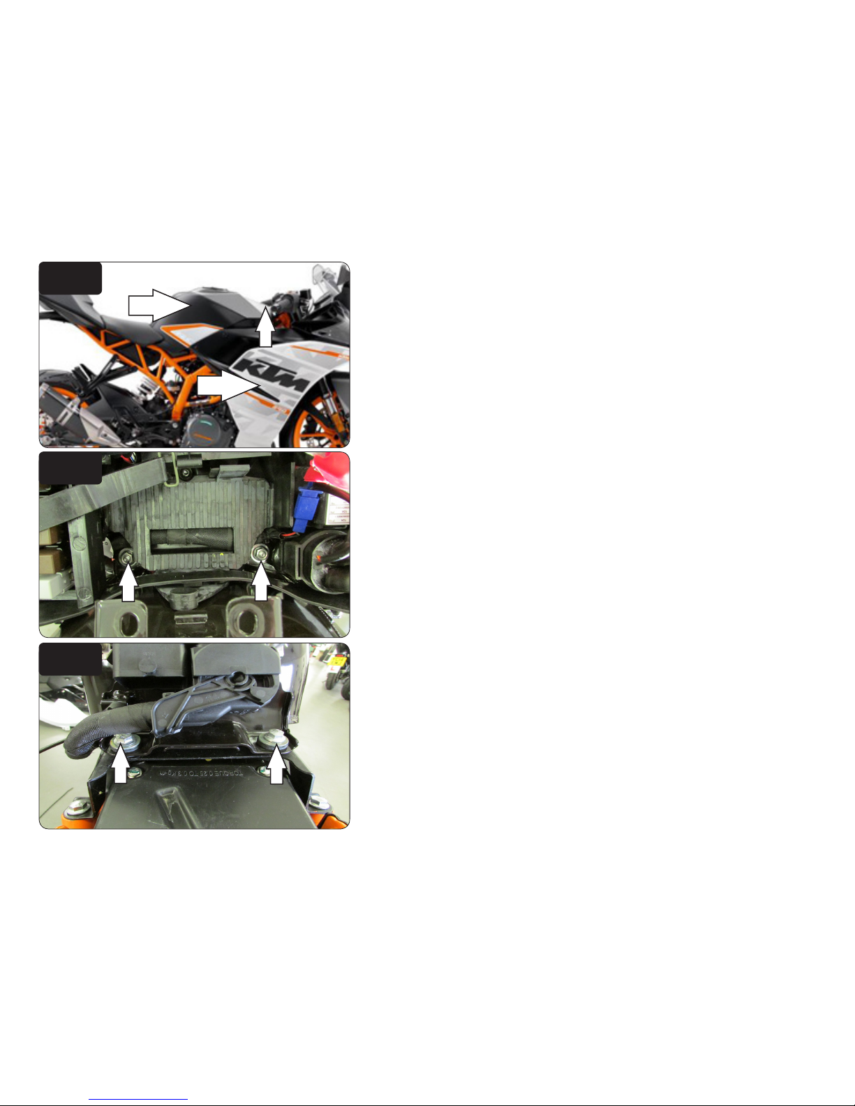
1 Remove the battery access cover, fuel tank cover, and side panels (Fig. A).
FIG.A
FIG.C
FIG.B
4 Remove the battery.
5 To remove the fuel tank remove the two bolts at the bottom of the battery box
(Fig. B).
6 Remove the 2 bolts at the rear of the fuel tank (Fig. C).
7 Unplug the wiring harness from the ECU and remove the fuel tank.
Page 4

18-023 www.powercommander.com 17-18 RC/Duke 390 - PCV - 4
FIG.F
FIG.D
FIG.E
8 Unplug the stock wiring harness from the ignition coil (Fig. D).
This is a BLACK, 2 pin connector on the right hand side.
9 Plug the PCV in-line of the stock wiring harness and stock ignition coil (Fig. E)
10 Unplug the stock Throttle Position Sensor connector (Fig. F).
This is a BLACK, 6 pin connector on the RH side of the throttle body.
11 Plug the PCV in-line of the stock TPS and wiring harness.
Unplug
Unplug
Stk
PCV
PCV
Page 5

18-023 www.powercommander.com 17-18 RC/Duke 390 - PCV - 5
FIG.G
FIG.H
FIG.J
12 Unplug the wiring harness from the fuel injector (Fig. G).
13 Plug the PCV in-line of the stock fuel injector and wiring harness (Fig. H).
14 Route the PCV harness as shown in Figure H and secure to the frame using
the zip tie.
15 Unplug the stock crank position sensor connector (Fig. J).
This is a WHITE, 6 pin connector near the FRT, LH side of the cylinder head.
Unplug
PCV harness
Unplug
Page 6

18-023 www.powercommander.com 17-18 RC/Duke 390 - PCV - 6
FIG.K
FIG.L
16 Plug the PCV in-line of the stock CPS and wiring harness (Fig. K).
Stk
PCV
17 Reinstall fuel tank and battery.
18 Secure the PCV to the front of the battery (Fig. L).
19 Attach the ground wire of the PCV to the negative side of the battery.
20 Reinstall bodywork.
 Loading...