

Page 1
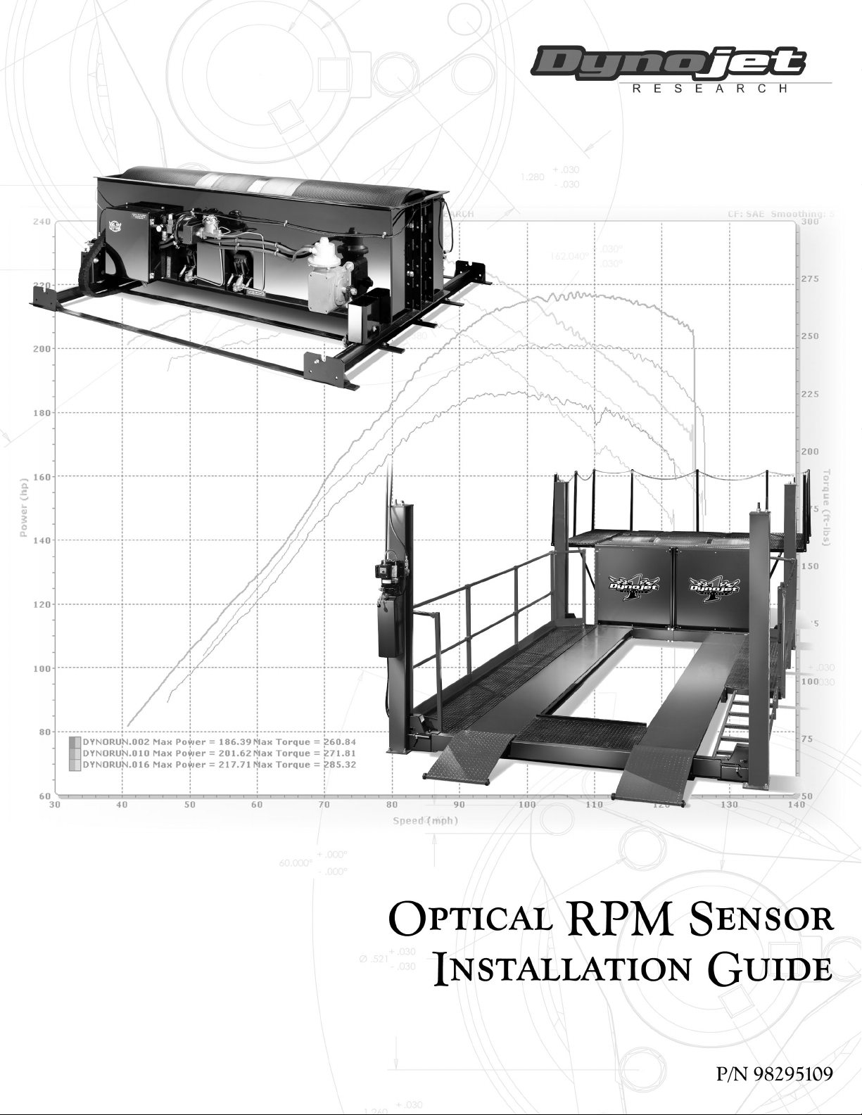
Page 2

©1993-2001 Dynojet Research, Inc. All Rights Reserved.
Optical RPM Sensor Installation Guide.
This manual is copyrighted by Dynojet Research, Inc., hereafter referred to as Dynojet,
and all rights are reserved. This manual, as well as the software described in it, is
furnished under license and may only be used or copied in accordance with the terms of
such license. This manual is furnished for informational use only, is subject to change
without notice, and should not be construed as a commitment by Dynojet. Dynojet
assumes no responsibility or liability for any error or inaccuracies that may appear in this
manual. Except as permitted by such license, no part of this manual may be reproduced,
stored in a retrieval system, or transmitted, in any form or by any means, electronic,
mechanical, recording, or otherwise, without the prior written permission of Dynojet.
The Dynojet logo is a trademark of Dynojet Research, Inc.
Any trademarks, trade names, service marks, or service names owned or registered by any
other company and used in this guide are the property of their respective companies.
Dynojet Research, Inc., 2191 Mendenhall Drive, North Las Vegas, Nevada 89031, USA.
Printed in USA.
Part Number: 98295109 (07/2001)
Page 3

T
ABLE OF
C
ONTENTS
List of Figures. . . . . . . . . . . . . . . . . . . . . . . . . . . . . . . . . . . . . . . . . . . . . iii
Chapter 1 Optical RPM Sensor Installation
Conventions Used In This Manual . . . . . . . . . . . . . . . . . . . . . . . . . . . . . . . . . . 1-1
Technical Support . . . . . . . . . . . . . . . . . . . . . . . . . . . . . . . . . . . . . . . . . . . . . . .1-2
Parts List . . . . . . . . . . . . . . . . . . . . . . . . . . . . . . . . . . . . . . . . . . . . . . . . . . . . . . .1-2
Installation . . . . . . . . . . . . . . . . . . . . . . . . . . . . . . . . . . . . . . . . . . . . . . . . . . . . .1-3
Connecting the Optical RPM Sensor . . . . . . . . . . . . . . . . . . . . . . . . . . . . . . .1-3
Optical Sensor Set Up and Adjustment . . . . . . . . . . . . . . . . . . . . . . . . . . . . .1-4
Running WinPEP . . . . . . . . . . . . . . . . . . . . . . . . . . . . . . . . . . . . . . . . . . . . . . . .1-6
Starting WinPEP . . . . . . . . . . . . . . . . . . . . . . . . . . . . . . . . . . . . . . . . . . . . . .1-6
Selecting a Name . . . . . . . . . . . . . . . . . . . . . . . . . . . . . . . . . . . . . . . . . . . . .1-7
Editing the Notes and Parameters . . . . . . . . . . . . . . . . . . . . . . . . . . . . . . . . .1-9
Preparing for a Run . . . . . . . . . . . . . . . . . . . . . . . . . . . . . . . . . . . . . . . . . . .1-13
Making a Test Run . . . . . . . . . . . . . . . . . . . . . . . . . . . . . . . . . . . . . . . . . . .1-14
Optical RPM Sensor Installation Guide
i
Page 4

Page 5

L
IST OF
Figure 1-1: Optical RPM Sensor Assembly Parts . . . . . . . . . . . . . . . . . . . . . . .1-2
Figure 1-2: Attach Reflective Tape To Harmonic Balancer . . . . . . . . . . . . . . .1-3
Figure 1-3: Hardware Stack—Optical Sensor and Power Lead . . . . . . . . . . .1-3
Figure 1-4: Optical Sensor—Mount To Magnetic Base . . . . . . . . . . . . . . . . .1-4
Figure 1-5: Optical Sensor—Verify Position And Proper Function. . . . . . . . .1-5
Figure 1-6: Error Message . . . . . . . . . . . . . . . . . . . . . . . . . . . . . . . . . . . . . . . . .1-6
Figure 1-7: WinPEP Setup Window—Dyno Parameters . . . . . . . . . . . . . . . . .1-6
Figure 1-8: Make Run Window—Select The Make . . . . . . . . . . . . . . . . . . . . .1-7
Figure 1-9: Make Run Window—Select The Model . . . . . . . . . . . . . . . . . . . . 1-7
Figure 1-10: Make Run Window—Select Name . . . . . . . . . . . . . . . . . . . . . . .1-8
Figure 1-11: Make Run Window—Example . . . . . . . . . . . . . . . . . . . . . . . . . .1-8
Figure 1-12: Make Run Window—Next Run Name and Run Title . . . . . . . .1-9
F
IGURES
Figure 1-13: Make Run Window—Plug Fires, Tachometer Redline,
and Tire Speed
Figure 1-14: Make Run Window—Run Type and Run Notes. . . . . . . . . . . . 1-11
Figure 1-15: Make Run Window—Optional Make Run Settings . . . . . . . . .1-12
Figure 1-16: Make Run Window—Gauges . . . . . . . . . . . . . . . . . . . . . . . . . .1-13
Figure 1-17: Test Run—Hand-Held Pendant . . . . . . . . . . . . . . . . . . . . . . . . . 1-14
. . . . . . . . . . . . . . . . . . . . . . . . . . . . . . . . . . . . . .1-10
Optical RPM Sensor Installation Guide
iii
Page 6

Page 7
O
PTICAL
RPM S
ENSOR INSTALLATION
C HAPTER
1
This document provides instructions for installing the Optical RPM Sensor. To ensure
safety and accuracy in the procedures, perform the procedures as they are described.
This manual will walk you through the installation procedures, running WinPEP and
using the tachometer to verify proper function, and describe how to make any
necessary adjustments.
Document Part Number: 98295109
Last Updated: 07-25-01
CONVENTIONS USED IN THIS MANUAL
The conventions used in this manual are designed to aid the user and protect both
the user and the equipment.
example of convention description
Bold Highlights items you can select on in the software
interface, including buttons and menus.
Indicates a keyboard command. For example, “press
U” means “using the keyboard, press the letter U.”
The Caution icon indicates a potential hazard to the
dynamometer equipment. Follow all procedures
exactly as they are described and use care when
performing all procedures.
The Warning icon indicates potential harm to the
person performing a procedure and/or the
dynamometer equipment.
Optical RPM Sensor Installation Guide
1-1
Page 8

CHAPTER 1
TECHNICAL SUPPORT
For assistance, please contact Dynojet Technical Support at 1-800-992-4993, or write
to Dynojet at 2191 Mendenhall Drive, North Las Vegas, NV 89031.
Visit us on the World Wide Web at www.dynojet.com where Dynojet provides state of
the art technical support, on-line shopping, 3D visualizations, and press releases
about our latest product line.
PARTS LIST
The following table lists all of the parts included in the Optical RPM Sensor
Installation kit. Check your kit against the parts listed to make sure you have received
all of the parts. If any part is missing, contact Dynojet Technical Support.
part number description quantity
Sensor Assembly with Bracket is pre-assembled and includes:
• Sensor, Optical RPM (P/N 49822000)
• Sensitivity Adjustment Tool
35130221 Magnetic Base, Diesel PU 1
66954003 Cable, Optical RPM Lead 1
38910490 Tape, Reflective, 1/2” 5 feet
1
optical sensor
lead
sensor assembly
with bracket
reflective tape
Figure 1-1: Optical RPM Sensor Assembly Parts
sensitivity
adjustment tool
magnetic base
1-2
Optical RPM Sensor Installation Guide
Page 9

OPTICAL RPM SENSOR INSTALLATION
INSTALLATION
. . . . . . . . . . . . . . . . . . . . . . . . . . . . . . . . . . .
This section describes the procedures for installing the optical RPM sensor.
CONNECTING THE OPTICAL RPM SENSOR
1 Cut a one inch strip of reflective tape from the roll provided.
2 Clean a flat section of the harmonic balancer. Attach the strip of reflective tape.
Note: High RPM engines will require a longer piece of reflective tape; use a
1.25-1.5-inch strip of tape.
reflective tape
Installation
Figure 1-2: Attach Reflective Tape To Harmonic Balancer
3 Attach the optical sensor lead to the hardware stack. You need to remove any
inductive leads from the RPM module if installed.
4 Attach the small power lead from the optical sensor lead to the CPU module.
optical sensor lead
on RPM module
optical sensor power
lead on CPU module
Figure 1-3: Hardware Stack—Optical Sensor and Power Lead
Optical RPM Sensor Installation Guide
1-3
Page 10

CHAPTER 1
Installation
5 Mount the optical sensor to the magnetic base. The base is adjustable to allow the
sensor to be oriented in many directions.
6 Attach the other end of the optical sensor lead into the optical sensor.
optical sensor
magnetic base
Figure 1-4: Optical Sensor—Mount To Magnetic Base
OPTICAL SENSOR SET UP AND ADJUSTMENT
1 Disconnect the negative battery cable. This will prevent the vehicle from starting.
2 Mount the optical sensor (attached to the magnetic base) in a location where the
red lens has an unobstructed view of the reflective tape.
Use the magnetic base on/off switch to secure the assembly to a stationary metal
object.
3 Connect the negative battery cable.
4 Verify the optical sensor is working.
Note: At this point you will need to skip to “Running WinPEP” on page 1-6 and
follow those instructions for making a run. These instructions will allow you to
use the tachometer gauge to verify whether the optical sensor is functioning
properly. Return to this section to adjust the optical RPM sensor as needed.
5 Verify the hardware stack is on.
6 Verify the optical sensor cable is plugged in to the RPM module and the power
lead from the cable is connected to the CPU module. Refer to Figure 1-3.
Note: Dynojet recommends you ground the vehicle to the dyno for the
electronics to function properly.
optical sensor lead
1-4
Optical RPM Sensor Installation Guide
Page 11

OPTICAL RPM SENSOR INSTALLATION
Installation
7 Verify both the green and red lights on the optical sensor are on. Both lights will
be on if the optical sensor in the correct position. The red lens on the sensor
must be pointed at the reflective tape.
If the red light is not on, the sensor will need to be relocated or adjusted. This
condition indicates that the sensor can not see the reflective tape.
Disconnect the negative battery cable any time you work under the front of the
vehicle. This will prevent the vehicle from starting and ensure your safety.
7a Try to relocate the magnetic base and sensor assembly closer to the
reflective tape. If this is not possible, you will need to adjust the sensitivity
on the sensor.
Be sure the placement of the magnetic base and sensor assembly do not
interfere with the operation of the vehicle. The vehicle’s fan may turn on at any
time; always use caution when working around the fan.
7b Use the adjustment tool to turn the sensitivity knob until both the green and
red lights are on at the same time.
Note: The red light will flash every time it sees the reflective tape. While running
the vehicle the red light will be flashing very fast and may be difficult to see.
red lens
red light
green light
Figure 1-5: Optical Sensor—Verify Position And Proper Function
sensitivity
adjustment tool
Optical RPM Sensor Installation Guide
1-5
Page 12

CHAPTER 1
Running WinPEP
RUNNING WINPEP
. . . . . . . . . . . . . . . . . . . . . . . . . . . . . . . . . . .
Use the following steps to run WinPEP, use the tachometer to verify the optical sensor
is functioning properly, and make a test run
Note: Depending on your version of WinPEP, the appearance of the windows and
messages may be slightly different than the ones used in this example.
STARTING WINPEP
1 Double-click the WinPEP icon on the desktop.
2Click the Make Run icon in the work space toolbar to display the Make Run
window.
Note: If the following error message is displayed, you will need to select a
different Com port (for DynoWare EX+) or a different address (for a PC Card).
2a Click OK to continue.
Figure 1-6: Error Message
2b The WinPEP Setup window will be displayed with the Dyno Parameters tab
automatically selected. Make any necessary corrections and click OK to
continue.
Figure 1-7: WinPEP Setup Window—Dyno Parameters
2c Once you have made your corrections, click the Make Run icon to display
the Make Run window.
1-6
Optical RPM Sensor Installation Guide
Page 13

SELECTING A NAME
Use the following procedures to set up your Make Run window and make a test run.
In this example we will use a Chevy Corvette owned by Larry Hall.
1 Select the Make.
1a Select Chevy from the file structure.
OPTICAL RPM SENSOR INSTALLATION
Running WinPEP
file structure
Figure 1-8: Make Run Window—Select The Make
2 Select the Model. If your model is not present in the file structure, you will need
to add your model to the list.
2a Press Insert to insert a new model.
2b Type the name of your model. You can use small or capital letters.
Example: CORVETTE
2c Click OK to continue.
Figure 1-9: Make Run Window—Select The Model
Optical RPM Sensor Installation Guide
1-7
Page 14

CHAPTER 1
Running WinPEP
3 Type the name of the owner. The name can be one to eight characters long with
no spaces and use small or capital letters.
Example: LARRY
4Click OK to continue.
Figure 1-10: Make Run Window—Select Name
Using the Corvette as an example, the Make Run window should look like
Figure 1-11 below.
Figure 1-11: Make Run Window—Example
1-8
Optical RPM Sensor Installation Guide
Page 15

EDITING THE NOTES AND PARAMETERS
You will need to fill in the Make Run data necessary for making a dyno run. We will
continue using the Corvette as an example.
Note: Absolute Pressure, Room Air Temperature, and Relative Humidity are
automatically determined by DynoWare’s Atmospheric module and cannot be
changed.
NEXT RUN NAME
Type in the name of the run. Refer to Figure 1-12. The name entered will appear on
the printed graph.
Example: LARRY.
RUN TITLE
Enter the description of the run in the Run Title.
Example: 94 CORVETTE ZR-1, 4TH GEAR TEST
OPTICAL RPM SENSOR INSTALLATION
Running WinPEP
next run name
Figure 1-12: Make Run Window—Next Run Name and Run Title
run title
Optical RPM Sensor Installation Guide
1-9
Page 16

CHAPTER 1
Running WinPEP
PLUG FIRES
TACHOMETER REDLINE
TIRE SPEED RATING
Enter 360 for the number of plug fires when using the optical RPM sensor. Refer to
Figure 1-13.
Enter the Tachometer Redline from your vehicle’s tachometer or your owner’s
manual. Refer to Figure 1-13.
Example: 7,250 RPM = 7.25
This places a redline on the tachometer that appears on the computer screen during a
run. If you exceed this redline during your run, the tachometer needle on the
computer screen will change colors.
From the following list, enter the Tire Speed Rating of the drive tires in mph for the
vehicle.
Note: If you exceed this speed, the computer will stop the run.
tire rating mph
Non-Rated 93 mph
S112 mph
tachometer redline
tire speed rating
H130 mph
V150 mph
Z150 mph and higher
plug fires
Figure 1-13: Make Run Window—Plug Fires, Tachometer Redline, and Tire Speed
1-10
Optical RPM Sensor Installation Guide
Page 17

OPTICAL RPM SENSOR INSTALLATION
Running WinPEP
RUN TYPE
Select the type of run you will be performing. Refer to Figure 1-14. A description of
each Run Type is listed below.
Example: RO
run type description
RO Roll-On
AG All Gear Run
FA Fast Accel er ation
NG Negative Horsepower
RUN NOTES
Enter up to five lines of information about your run.
Example: 4TH GEAR ROLL ON TEST, LARRY HALL’S 1994 CORVETTE, ZR-1 BEFORE
FULL SERVICE, TUNE-UP.
Figure 1-14: Make Run Window—Run Type and Run Notes
run type
run notes
Optical RPM Sensor Installation Guide
1-11
Page 18

CHAPTER 1
Running WinPEP
OPTIONAL MAKE RUN SETTINGS
Auto Download—automatically saves a delimited text file in a numbers data format
after each run. The name of the file will be the same as the run with a DAT extension
and will be stored in the same directory as the run.
Hold BaseLine—when this option is checked the first run in the selection list or the
first run made is held in the number one slot on the graph for comparison.
To change the base run, change the run in the number one slot in the selection list on
the work group form.
Graph Data Following Run—this option allows you to toggle the graph on and off
after making a run.
Display Neg Values—allows you to view negative values on the graph after making
a run.
Once all of the notes and parameters have been entered, click Make Run or press
Enter to start the run.
1-12
Optical RPM Sensor Installation Guide
optional make
run settings
Figure 1-15: Make Run Window—Optional Make Run Settings
Page 19

OPTICAL RPM SENSOR INSTALLATION
Running WinPEP
The following gauges window will appear. The tachometer gauge will be used to
verify the optical RPM sensor is functioning properly. Refer to Make a Test Run, step 2
on page 1-14 for instructions on testing the tachometer.
PREPARING FOR A RUN
Use the following procedures and safety checks to prepare for a run.
BEFORE STARTING THE ENGINE
1 Connect an exhaust hose or hoses (if dual exhaust) on the car, make sure the
hose fits over the tail pipe, is not plugged or kinked, and the hose is vented
correctly out of the dyno room.
2 Perform the following safety checks:
✓ Check the radiator coolant and oil levels.
✓ Check the tire pressure and tire speed rating. Improperly inflated tires or
exceeding the maximum speed rating can result in premature wear or severe
tire damage.
✓ Check the tie-down straps to make sure that they are tight and secured.
✓ Check the drive tires to be sure that they are aligned correctly on the
dynamometer drums.
✓ Visually inspect the vehicle. Make sure it is in safe, running order.
✓ Make sure to wear safety glasses and ear protection when operating the dyno.
✓ Keep all rotating components clear at all times.
✓ Only the operator should be near the dyno or the vehicle during the test.
✓ Never allow any person(s) to stand behind the dyno or vehicle when it is being
operated.
✓ Perform any other safety inspections appropriate to running your car on the
dyno.
Figure 1-16: Make Run Window—Gauges
Optical RPM Sensor Installation Guide
1-13
Page 20

CHAPTER 1
Running WinPEP
ENGINE WARM UP
3 Warm the vehicle’s engine and drivetrain before beginning testing. Consistent
engine temperatures will assure your runs are repeatable.
FOLLOWING ENGINE WARM UP
4 When you exit a vehicle while still on the dyno, always leave the vehicle in Park
(automatic transmission) or in first gear (manual transmission); turn the engine
off; and make sure both the vehicle emergency brake and the dyno brake are on.
5 Repair any fuel, oil, or coolant leaks that may have appeared after engine warm
up. Check the carburetor for leaks.
6 Inspect any loud or unusual engine noises or excessive exhaust smoke. These
issues must be resolved before continuing.
MAKING A TEST RUN
Make sure that the vehicle is secured properly.
1 Accelerate the vehicle.
1a Place the vehicle in a low gear and release the dyno brake using the
1b Slowly accelerate the vehicle to about 20 mph.
hand-held pendant.
1-14
Optical RPM Sensor Installation Guide
Figure 1-17: Test Run—Hand-Held Pendant
2 Test the tachometer.
If the tachometer does not move, you will need to adjust the optical RPM sensor.
Refer to “Optical Sensor Set Up and Adjustment” on page 1-4 for instructions on
adjusting the sensor.
If the tachometer is moving but not registering the correct RPM values, the
number entered for Plug Fires may be incorrect. Stop the vehicle, press Escape to
return to the Make Run window and enter the correct value for the plug fires.
Refer to page 1-10 for more information about plug fires.
Note: You should now be able to use the optical RPM sensor. Continue with step
3 to stop the vehicle and step 4 if you are planning to perform a high speed run
on the dyno.
Page 21

OPTICAL RPM SENSOR INSTALLATION
Running WinPEP
3 Stop the vehicle.
3a Remove your foot from the accelerator pedal.
3b Take the vehicle out of gear (manual transmission only).
3c Press brake button on the hand-held pendant to stop the dyno drums.
Do NOT use the vehicle’s own brakes to slow the dyno drums! Using only the
vehicle’s brake to stop the drums will severely over stress the vehicle’s brake
parts. The vehicle’s brakes should be used in emergency stop situations only.
3d Shut the engine off.
3e Put the vehicle in gear (manual transmission) or park (automatic
transmission).
3f Set the vehicle’s emergency brake. Leave the dyno brake on.
4Check the straps.
4a Make any adjustments to the straps that may be needed.
4b Verify the drive tire’s alignment on the dyno drums.
4c Perform any other safety checks that you deem appropriate to your
particular situation.
You are now ready to perform a high speed run on the dyno.
Optical RPM Sensor Installation Guide
1-15
Page 22

 Loading...