

Page 1
Page 2

©2007 Dynojet Research, Inc. All Rights Reserved.
Dynojet Data Link Module-OBDII Installation and User Guide
This manual is copyrighted by Dynojet Research, Inc., hereafter referred to as Dynojet,
and all rights are reserved. This manual, as well as the software described in it, is
furnished under license and may only be used or copied in accordance with the terms of
such license. This manual is furnished for informational use only, is subject to change
without notice, and should not be construed as a commitment by Dynojet. Dynojet
assumes no responsibility or liability for any error or inaccuracies that may appear in this
manual. Except as permitted by such license, no part of this manual may be reproduced,
stored in a retrieval system, or transmitted, in any form or by any means, electronic,
mechanical, recording, or otherwise, without the prior written permission of Dynojet.
The Dynojet logo is a trademark of Dynojet Research, Inc.
Any trademarks, trade names, service marks, or service names owned or registered by any
other company and used in this guide are the property of their respective companies.
Dynojet Research, Inc., 2191 Mendenhall Drive, North Las Vegas, Nevada 89081, USA.
Printed in USA.
Part Number: 98100005 Version 04 (09/07)
Page 3

T
ABLE OF
C
ONTENTS
Data Link Module-OBDII
Introduction
Computer Specifications . . . . . . . . . . . . . . . . . . . . . . . . . . . . . . . . . . . . . . . 2
Conventions Used In This Manual . . . . . . . . . . . . . . . . . . . . . . . . . . . . . . . . 3
Technical Support . . . . . . . . . . . . . . . . . . . . . . . . . . . . . . . . . . . . . . . . . . . . 3
DJDLM-OBDII Setup
Installing the DJDLM-OBDII . . . . . . . . . . . . . . . . . . . . . . . . . . . . . . . . . . . . . 4
Configuring the DJDLM-OBDII . . . . . . . . . . . . . . . . . . . . . . . . . . . . . . . . . . . 5
Troubleshooting Connection Errors . . . . . . . . . . . . . . . . . . . . . . . . . . . . . . . 7
Dynojet DLM-OBDII Dialog Box—Config Tab
Entering the Vehicle Information . . . . . . . . . . . . . . . . . . . . . . . . . . . . . . . . 10
Dynojet DLM-OBDII Dialog Box—Channels Tab
Verifying the Supported Channels . . . . . . . . . . . . . . . . . . . . . . . . . . . . . . . 11
Using Filters . . . . . . . . . . . . . . . . . . . . . . . . . . . . . . . . . . . . . . . . . . . . . . . . 12
Enabling Channels . . . . . . . . . . . . . . . . . . . . . . . . . . . . . . . . . . . . . . . . . . . 13
Using Active Channels . . . . . . . . . . . . . . . . . . . . . . . . . . . . . . . . . . . . . . . . 14
Dynojet DLM-OBDII Dialog Box—Trouble Codes
DJDLM-OBDII and WinPEP 7
Configuring the MakeRun Screen . . . . . . . . . . . . . . . . . . . . . . . . . . . . . . . 16
Viewing the Results . . . . . . . . . . . . . . . . . . . . . . . . . . . . . . . . . . . . . . . . . . 18
. . . . . . . . . . . . . . . . . . . . . . . . . . . . . . . . . . . . . . . . . . . . . . . . . . . 2
. . . . . . . . . . . . . . . . . . . . . . . . . . . . . . . . . . . . . . . . . . . . 4
. . . . . . . . . . . . . . . . . . . . . . . 8
. . . . . . . . . . . . . . . . . . . 11
. . . . . . . . . . . . . . . . . . . 15
. . . . . . . . . . . . . . . . . . . . . . . . . . . . . . . . . . . . 16
Appendix A Data Link Module-OBDII Basic Configuration
Introduction
Connecting the DJDLM-OBDII . . . . . . . . . . . . . . . . . . . . . . . . . . . . . . . . . .A-3
Configuration
Accessing the Boot Options Window . . . . . . . . . . . . . . . . . . . . . . . . . . . . .A-4
Configuring the DJDLM-OBDII as a Stand Alone Wireless Device . . . . . . . .A-5
Configuring the DJDLM-OBDII as a Wireless Client . . . . . . . . . . . . . . . . . .A-6
Configuring the DJDLM-OBDII with a Category 5 Crossover Cable . . . . . .A-8
Configuring the DJDLM-OBDII with a Category 5 Standard Cable . . . . . . .A-8
Index
. . . . . . . . . . . . . . . . . . . . . . . . . . . . . . . . . . . . . . . . . . . . . . . . . .A-2
. . . . . . . . . . . . . . . . . . . . . . . . . . . . . . . . . . . . . . . . . . . . . . . .A-4
. . . . . . . . . . . . . . . . . . . . . . . . . . . . . . . . . . . . . . . . . . . . . . . . . Index-i
Data Link Module-OBDII Installation and User Guide
i
Page 4

Page 5

D
ATA
L
INK
M
ODULE
-OBDII
Thank you for purchasing the Dynojet Data Link Module-OBDII (DJDLM-OBDII). The
DJDLM-OBDII allows data, such as spark advance, throttle position, head
temperature, inlet air temperature, and numerous other parameters to be transmitted
from the vehicle’s OBDII compatible Powertrain Control Module (PCM) via the
vehicle’s data port. The WinPEP 7 software lets you easily view, save, and compare this
data using just a few mouse clicks.
The DJDLM-OBDII is great for PCM tuning and maintaining consistency while dyno
testing. No need to guess if the vehicle is too hot, or perhaps if the PCM is retarding
timing. You can even show this information right along side your dyno results using
the WinPEP 7 software.
Dynojet Research is known for its ultra consistent and repeatable line of chassis
dynos, and now with the DJDLM-OBDII you can gather data directly from the vehicle
being tested to achieve even greater consistency. This innovation is just another
example of the professional results you gain using Dynojet products.
Document Part Number: 98100005
Versi o n 4
Last Updated: 09-12-07
Data Link Module-OBDII Installation and User Guide
1
Page 6

DATA LINK MODULE-OBDII
Introduction
INTRODUCTION
. . . . . . . . . . . . . . . . . . . . . . . . . . . . . . . . . . .
Before you begin using WinPEP 7 (Performance Evaluation Program for Windows)
with your DJDLM-OBDII, be sure to read this guide for important system
requirements and installation instructions. Refer to the Dynojet WinPEP 7 User Guide
(P/N 98118103) for detailed information about WinPEP 7 features and commands, a
theoretical background, and a hands-on tutorial.
C
OMPUTER SPECIFICATIONS
You will need to provide a computer system to run the WinPEP software.
minimum system requirements recommended systems requirements
• Microsoft® Windows 2000/XP • Microsoft® Windows 2000/XP
• Pentium 800 MHz Processor • 2.4 GHz Processor or greater
• 256 MB of available RAM • 512 MB of available RAM or greater
• one 9-pin COM port, two 9-pin COM ports for
• USB port for DJDLM-OBDII, additional USB
• 800 x 600, 256 color monitor (SVGA) • 1280 x 1024 256 color monitor (SXGA) or better
• 1.2 gigabyte hard drive • 40 gigabyte hard drive
• 30 MB of available hard-disk space • 100 MB of available hard-disk space
• CD ROM • CD ROM
• printer, if hard copies are needed • printer, if hard copies are needed
• wired or wireless network capability • wireless network capability
Tuning Link
ports may be desired for other accessories
• one 9-pin COM port, two 9-pin COM ports for
Tuning Link
• USB port for DJDLM-OBDII, additional USB ports
may be desired for other accessories
2
Data Link Module-OBDII Installation and User Guide
Page 7

C
ONVENTIONS USED IN THIS MANUAL
The conventions used in this manual are designed to protect both the user and the
equipment.
example of convention description
Bold
!
T
ECHNICAL SUPPORT
For assistance, please contact Dynojet Technical Support at 1-800-992-3525, or write
to Dynojet at 2191 Mendenhall Drive, North Las Vegas, NV 89081.
Visit us on the World Wide Web at www.dynojet.com where Dynojet provides state of
the art technical support, on-line shopping, and information about our latest product
lines.
Highlights items you can select on in the software
interface, including buttons and menus.
The arrow indicates a menu choice. For example,
File !Open”
“select
then select the
Open
DATA LINK MODULE-OBDII
Introduction
means “select the
choice on the
File
File
menu,
menu.”
Version 4 Data Link Module-OBDII Installation and User Guide
3
Page 8
DATA LINK MODULE-OBDII
DJDLM-OBDII Setup
DJDLM-OBDII SETUP
. . . . . . . . . . . . . . . . . . . . . . . . . . . . . . . . . . .
This section provides basic instructions for setting up the DJDLM-OBDII with
WinPEP 7. To ensure safety and accuracy, perform the procedures as they are
described.
part description quantity
DJDLM-OBDII (P/N 76100008) includes the following:
42900000 cat5e patch cable, 15', black 1
42900001 cat5e crossover patch cable, 14', red 1
66100005 OBDII Data Link Module, with antenna and
15-pin cable
I
NSTALLING THE
1 Connect the DJDLM-OBDII to the vehicle’s data port. The data port is usually
2 Connect the DJDLM-OBDII to your computer, where you are running the WinPEP
3 Turn the vehicle’s key to the ON position. The engine may need to be running on
connect antenna for
wireless networks
DJDLM-OBDII
located on the driver’s side underneath the dash.
software, using either the wired or wireless network. Verify that your computer
system has network connectivity with the DJDLM-OBDII.
some vehicles in order to power the DJDLM-OBDII.
use red cat5 crossover cable
to connect to peer to peer
wired network
1
use black standard cat5
cable to connect to a
wired network hub
4
Data Link Module-OBDII Installation and User Guide
connect to
vehicle’s data port
DJDLM-OBDII
module
Figure 1: Installing the DJDLM-OBDII
connect the15-pin
cable to the
DJDLM-OBDII
Page 9
C
ONFIGURING THE
1 Start the WinPEP software by double-clicking the desktop icon or by selecting
Start
When WinPEP starts, the Graph View shows by default.
2Click the MakeRun button on the toolbar or select Display
Screen from the menu choices.
3 Verify your computer is connected to the dyno electronics and the dyno
electronics is powered on. Refer to "Connecting the Dyno Electronics" in your
WinPEP 7 User Guide for more information.
4Click the MakeRun Configuration button .
Note: If You may have more than one DJDLM-OBDII connected to your network
at the same time, a window will pop up. Choose which device you wish to
connect to.
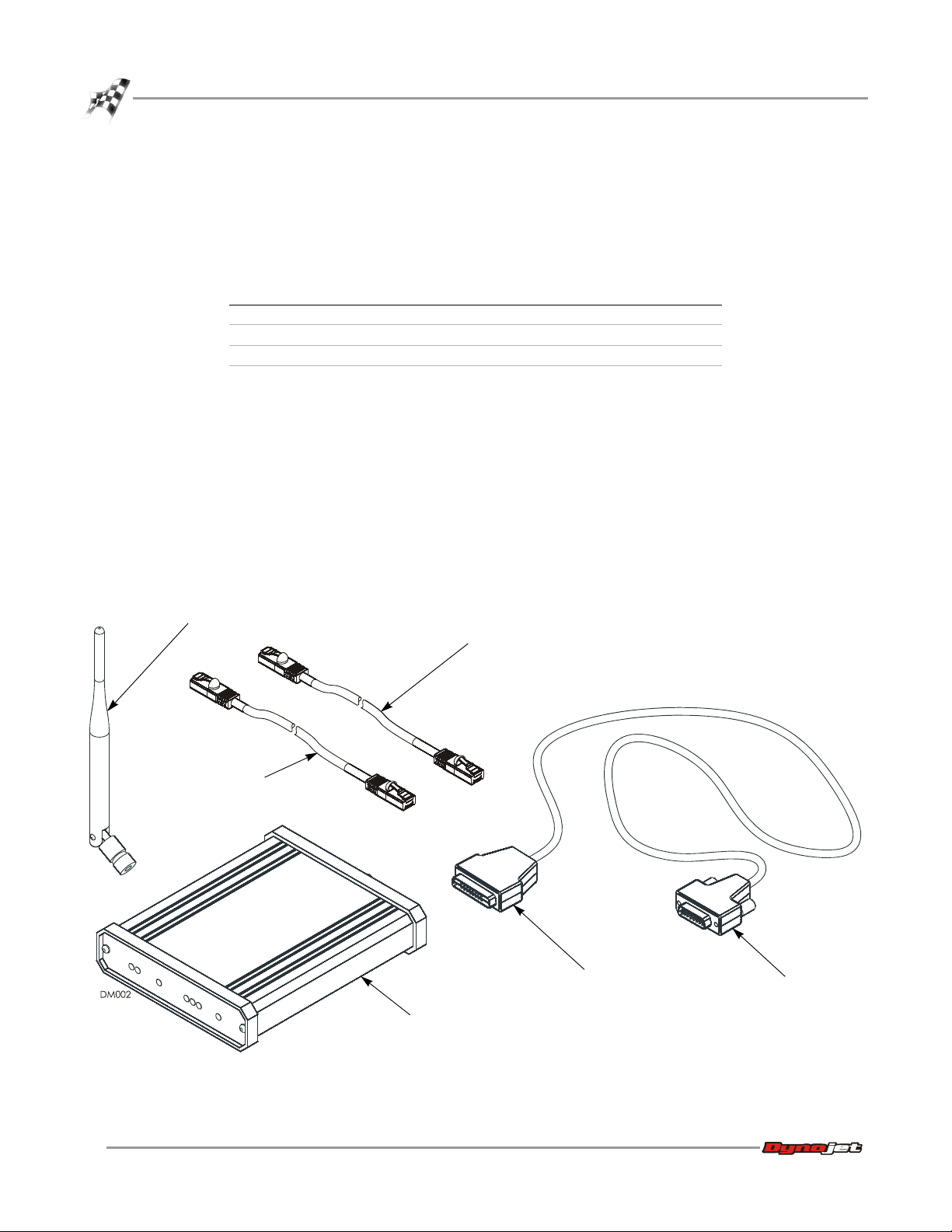
5Click the Expansion Systems tab.
6Select Dynojet DLM-OBDII.
7Click the Configure button.
DJDLM-OBDII
!
All Programs !WinPEP 7 !WinPEP 7.
DATA LINK MODULE-OBDII
DJDLM-OBDII Setup
!
MakeRun
select Dynojet
DLM-OBDII
expansion
systems tab
configure
button
Figure 2: MakeRun Configuration—Expansion Systems
Version 4 Data Link Module-OBDII Installation and User Guide
5
Page 10
DATA LINK MODULE-OBDII
DJDLM-OBDII Setup
DJDLM-OBDII
device is
connected with
your computer
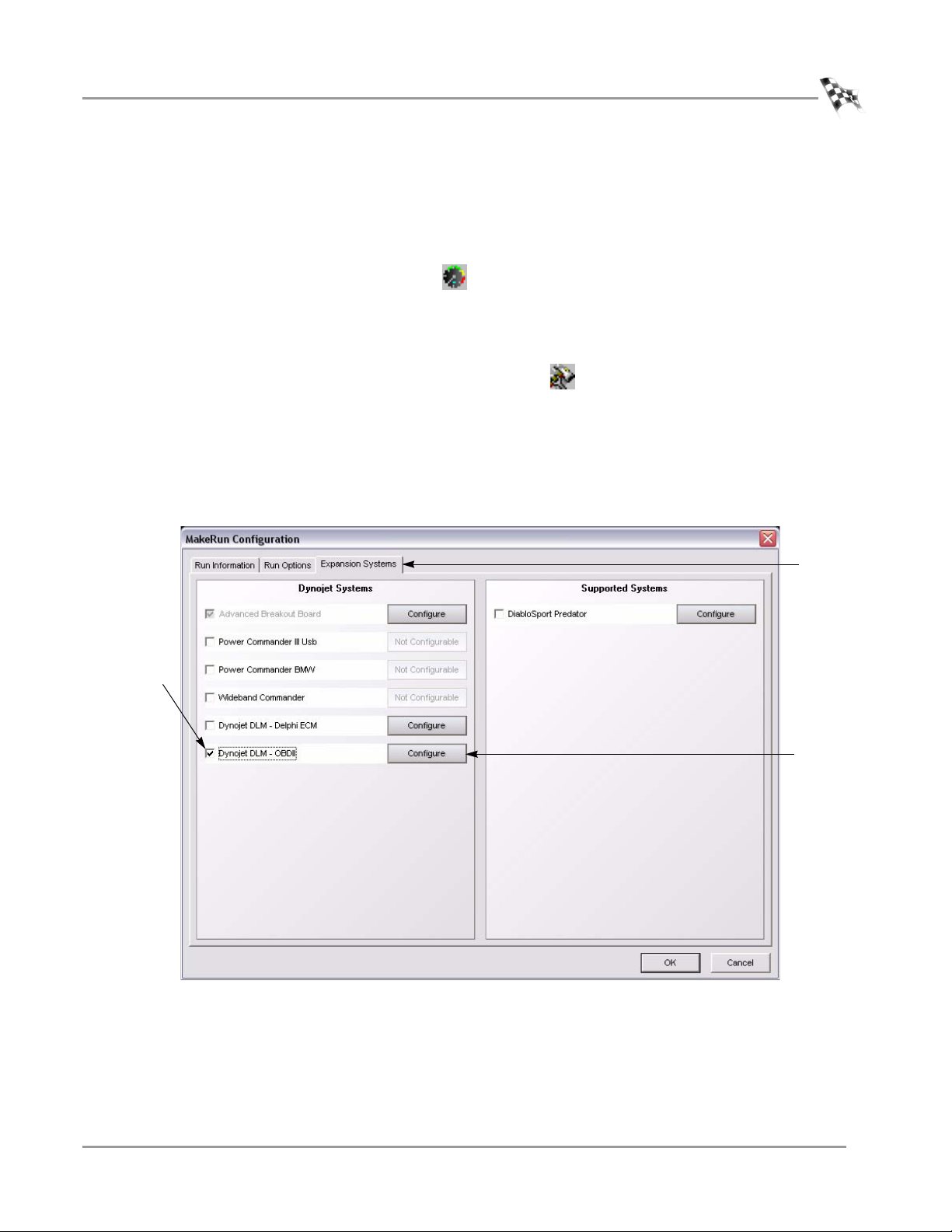
The Dynojet DLM-OBDII dialog box will appear. When the DJDLM-OBDII is
properly connected to your computer system, the Status area will indicate you are
connected.
If you are unable to connect, refer to “Troubleshooting Connection Errors” on
page 7.
Figure 3: Dynojet DLM-OBDII Dialog Box—Status Connected
6
Data Link Module-OBDII Installation and User Guide
Page 11

T
ROUBLESHOOTING CONNECTION ERRORS
If you are unable to connect to the DJDLM-OBDII and the PCM, use the following
table to troubleshoot your connection.
If you still cannot establish a connection, contact Dynojet Technical Support.
problem try this then this
DJDLM-OBDII:
Disconnected
DJDLM-OBDII:
Disconnected
DJDLM-OBDII:
Disconnected
PCM:
Disconnected
Verify your computer is connecting
to your network through a wired or
wireless network card.
Click Reconnect. Verify the cable is plugged into your
Verify the vehicle power is turned
on; if there is a ready to start switch
verify it is on.
Verify the vehicle power is turned
on; if there is a ready to start switch
verify it is on; start the vehicle if
necessary.
Click Reconnect.
Verify the network cable is making a
connection or the wireless network is
broadcasting.
computer and is making a connection.
Press F5 to reset.
Start the vehicle; some vehicles do not
provide enough power to the DJDLMOBDII unless started.
Check the plug end to the vehicle’s
data port; this occasionally may
appear to “snap” into place, but may
not be making connection.
Press F5 to reset.
DATA LINK MODULE-OBDII
DJDLM-OBDII Setup
Version 4 Data Link Module-OBDII Installation and User Guide
7
Page 12

DATA LINK MODULE-OBDII
Dynojet DLM-OBDII Dialog Box—Config Tab
DYNOJET DLM-OBDII DIALOG BOX—CONFIG TAB
. . . . . . . . . . . . . . . . . . . . . . . . . . . . . . . . . . .
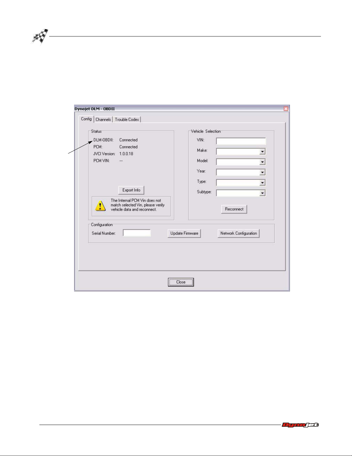
The Dynojet DLM-OBDII dialog box allows sophisticated configuration of your
DJDLM-OBDII. A description of the Config tab functions and displays follows:
Figure 4: Dynojet DJDLM-OBDII Dialog Box—Config Tab
DJDLM-OBDII—displays Connected when the DJDLM-OBDII is connected to your
computer via the network. Displays Disconnected when the DJDLM-OBDII cannot
communicate with your computer. The DJDLM-OBDII must be able to connect to the
8
Data Link Module-OBDII Installation and User Guide
computer before it can connect to the vehicle’s PCM.
PCM—displays Connected when the DJDLM-OBDII is connected to the vehicle’s
PCM. Displays Disconnected when the DJDLM-OBDII cannot communicate with the
PCM.
Page 13

DATA LINK MODULE-OBDII
Dynojet DLM-OBDII Dialog Box—Config Tab
Version—displays the software .dll version used by the DJDLM-OBDII hardware. This
.dll version must be the correct one for your WinPEP software version. If your versions
do not match, contact Dynojet technical support or check for an update on
www.dynojet.com.
PCM Vin—displays the vehicle identification number (VIN) detected from the PCM if
it is available.
Export Info—creates a text file for debugging purposes and may be requested by
technical support.
Serial Number—the serial number for your DJDLM-OBDII identifies it as a unique
device on your computer network. Before selecting Update Firmware or Network
Configuration, specify the serial number of the DJDLM-OBDII to update. Otherwise
the software will find the first available DJDLM-OBDII on the network.
Update Firmware—displays a window used to update your DJDLM-OBDII if
necessary.
Network Configuration—displays a window used to configure your DJDLM-OBDII
to connect to your computer network if necessary. When the DJDLM-OBDII is
properly connecting to your computer system, the Status area will indicate the
DJDLM-OBDII is connected.
VIN—usually the seventeen digit identification number specific to your vehicle; any
text or digits is a valid entry.
Make—use the drop down list to select the vehicle manufacturer, such as Ford or
GMC. You must select Ford or GM to view enhanced channels.
Model—use the drop down list to select the model, such as Mustang, or Bronco.
Year—use the drop down list to select the manufacture year for your vehicle.
Type—when there are variations among the models for a year, the type will be listed
so that you may select it from the drop down list.
Subtype—if further variations (often engine size) exist, the subtype will be listed so
that you may select it from the drop down list.
Note: Because the OBDII standard is used for data from many types of vehicles,
you may be able to retrieve data using your DJDLM-OBDII even when you have
not configured for your specific vehicle. It is generally better to configure for your
vehicle using as much specific information as you have available.
Version 4 Data Link Module-OBDII Installation and User Guide
9
Page 14

DATA LINK MODULE-OBDII
Dynojet DLM-OBDII Dialog Box—Config Tab
E
NTERING THE VEHICLE INFORMATION
1 Enter the vehicle’s VIN number.
2 Using the drop down list, select the vehicle’s make.
Note: You must fill in the vehicle’s make information in order to see enhanced
channels.
3 Using the drop down list, select the vehicle’s model.
4 Using the drop down list, select the vehicle’s year.
5 Using the drop down list, select the vehicle’s type and subtype if applicable.
6Click Reconnect to send the information to the DJDLM-OBDII.
The DJDLM-OBDII will update the list of channels based on the information you
have entered.
10
Data Link Module-OBDII Installation and User Guide
Figure 5: Entering the Vehicle Information
Page 15

DYNOJET DLM-OBDII DIALOG BOX—CHANNELS TAB
. . . . . . . . . . . . . . . . . . . . . . . . . . . . . . . . . . .
The Channels tab displays the available channels and allows you to verify and enable
channels.
V
ERIFYING THE SUPPORTED CHANNELS
To determine whether a channel is supported, the DJDLM-OBDII must communicate
with the vehicle’s PCM. You must verify the channel is supported before you can
enable a channel for use.
1 Click anywhere in the row containing a channel to select a single channel,
Ctrl+click to select multiple channels, or use Ctrl+A to select all channels.
2Click Veri f y to communicate with the PCM to determine whether the channel is
supported.
click a channel
to select it
DATA LINK MODULE-OBDII
Dynojet DLM-OBDII Dialog Box—Channels Tab
Figure 6: Channels Tab—Verifying the Supported Channels
Version 4 Data Link Module-OBDII Installation and User Guide
11
Page 16

DATA LINK MODULE-OBDII
Dynojet DLM-OBDII Dialog Box—Channels Tab
U
SING FILTERS
Use filters to sort and refine the list of displayed channels.
1 Click a column heading to sort using that column. Click and drag a divider to
resize the column.
2 Select a filter from the list. In this example, Supported has been selected.
3 Enter text in the Name Includes/Abrev Includes fields. In this example, Air has
been entered in the Name Includes field.
4Select And to show only channels that meet all of the selected filter criterion.
Select Or to show all of the channels that meet any of the selected filter criterion.
Note: Selecting Enabled and Unsupported using the And button will not show
any channels because there are no channels that can be both unsupported and
enabled.
5Click Apply to update the list using your selections.
The software stores which filters you have selected. They will already be active the
next time you enter the Channels screen.
6Click Clear to clear the filter selections.
click a
column
heading to
sort using
that column
hovering your
mouse over a
truncated
name shows
the full name
channels that
are supported
or have air in
their name
appear listed
click and
drag a
divider to
resize the
column
12
Data Link Module-OBDII Installation and User Guide
Figure 7: Channels Tab—Using Filters
Page 17

channel
enabled
E
NABLING CHANNELS
Enabling is different than verifying channels. Any unsupported channels return to the
disabled state. You cannot enable unsupported channels. Having more than six
generic channels enabled at one time will slow down the incoming data rate. The
lower your data rate, the less precise your data will be.
1 Once a channel or channels have been selected, click Enable.
2Click Close to exit the dialog box.
3Click OK to exit the MakeRun Configuration dialog.
Enabled channels appear with *C_ in front of their abbreviated name in the list of
available WinPEP channels.
The Absolute Throttle Position channel shown below was verified. Since the PCM
has verified that it is able to provide data for this channel it shows as supported. It
has also been enabled for use in WinPEP. *C_TP is now in the list of available Data
Channels, refer to Figure 11.
Note: You cannot enable unsupported channels.
DATA LINK MODULE-OBDII
Dynojet DLM-OBDII Dialog Box—Channels Tab
channel is
supported
Figure 8: Channels Tab—Enabling Channels
Version 4 Data Link Module-OBDII Installation and User Guide
13
Page 18

DATA LINK MODULE-OBDII
Dynojet DLM-OBDII Dialog Box—Channels Tab
U
SING ACTIVE CHANNELS
The Active Channels tab allows you to store your list of channels. Only enabled
channels can be stored for later retrieval.
1Click the Active Channels tab.
2Select Default Path or Current Run Path.
Default Path saves your channel settings in the WinPEP directory. Current Run
Path saves your channel settings in the location you are currently using for your
dyno runs.
Note: Using separate folders within the DynoRuns folder for each vehicle type
allows you to organize and find your dyno runs. Using Current Run Path in
conjunction with organized folders will help you automatically see the channels
you use for the type of vehicle in that folder.
3Click Save to store this list of channels for easy connection in the future.
Note: Selecting Autosave on Exit automatically saves any changes to your active
channels list when you exit the dialog box.
this list has
been filtered
to only include
channels with
rpm in the
name
select to save
your active
channel list
to the default
software
location or to
the current
run location
select to
automatically
save any
changes to
your channel
list on
exiting
Figure 9: Channels Tab—Active Channels
14
Data Link Module-OBDII Installation and User Guide
Page 19

DATA LINK MODULE-OBDII
Dynojet DLM-OBDII Dialog Box—Trouble Codes
DYNOJET DLM-OBDII DIALOG BOX—TROUBLE CODES
. . . . . . . . . . . . . . . . . . . . . . . . . . . . . . . . . . .
The DJDLM-OBDII will only read back codes if the check engine light is on.
1Click Request Codes to display the trouble codes available from the vehicle’s
PCM.
Note: To display trouble codes, the DJDLM-OBDII must be communicating with
the vehicle’s PCM.
2Click Save to save the trouble code information to a text file.
3Click Clear Codes to clear the vehicle’s trouble codes. Always wait a few minutes
after clearing trouble codes before requesting codes again.
Figure 10: Dynojet DLM-OBDII Dialog Box—Trouble Codes
Version 4 Data Link Module-OBDII Installation and User Guide
15
Page 20

DATA LINK MODULE-OBDII
DJDLM-OBDII and WinPEP 7
DJDLM-OBDII AND WINPEP 7
. . . . . . . . . . . . . . . . . . . . . . . . . . . . . . . . . . .
Features within WinPEP 7 may use the supported data channels enabled in the
DJDLM-OBDII.
C
ONFIGURING THE MAKERUN SCREEN
The gauges displayed on the MakeRun screen are completely configurable. Editing a
gauge allows live data from the DJDLM-OBDII to be displayed on the MakeRun
screen. Any data from the DJDLM-OBDII will always be recorded when you sample a
run. Dynojet recommends displaying live gauges on the MakeRun screen to help
verify data is streaming from the DJDLM-OBDII to WinPEP 7.
For more detailed information on gauges, refer to the WinPEP 7 User Guide.
1Click the Edit Mode button . You cannot edit gauges unless you are in Edit
Mode.
The gauge toolbar will appear.
2 Choose the style of gauge you would like.
3 Click and drag, holding the mouse button down as you do so, on the MakeRun
screen until the dotted box is the desired size. Release the mouse and the gauge
will appear.
4 Edit the gauge properties.
4a Right click on the gauge and choose Gauge Properties.
The Gauge Property Editor dialog box will appear.
4b Select a Data Channel from the drop down list.
Each type of gauge has a slightly different dialog box, but most share the same
properties. Most channels available are standard channels, but the channels that
are listed with an asterisk are from peripheral devices (Expansion Systems).
The Prefix *C_ indicates data channels that are available from the DJDLM-OBDII.
Other expansion systems have an asterisk (*) in front of the channel name. Data
channels without an asterisk (*) in front of their names are information from your
dyno.
Data Channel determines which channel the gauge is linked to (such as the
DJDLM-OBDII). The data channels that you selected when you configured your
DJDLM-OBDII are the ones that are available. If you do not see a data channel that
you think should be shown, make sure that it is a supported channel that you
enabled when configuring your device as shown on page 11. Some types of
gauges automatically place the name of the Data Channel selected on the gauge.
Digital gauges do not display the name and will require you to add a label.
Note: You must be connected to the dyno electronics for the list of channels to be
available.
16
Data Link Module-OBDII Installation and User Guide
Page 21

edit mode
button
DATA LINK MODULE-OBDII
DJDLM-OBDII and WinPEP 7
4c Click OK to enter these changes or click Cancel to abort the changes and
return to the MakeRun screen.
data channel
drop down list
Figure 11: Segment Display Property Editor—Data Channels
Version 4 Data Link Module-OBDII Installation and User Guide
17
Page 22

DATA LINK MODULE-OBDII
DJDLM-OBDII and WinPEP 7
V
IEWING THE RESULTS
Data streaming from the PCM during the dyno run is available to be graphed right
along side all of the standard channels such as HP, Trq, AFR, and rpm. This feature will
be instrumental to assist you with troubleshooting, tuning, and maintaining
consistency during dyno testing.
Note: Rpm cannot be graphed on the horizontal axis due to the sampling rate
from the vehicle sensors. WinPEP provides graphing of rpm on the vertical axis.
streaming data
channels
Figure 12: Graph Example
18
Data Link Module-OBDII Installation and User Guide
Page 23

A
PPENDIX
D
ATA
The appendix contains instructions for configuring the Dynojet Data Link ModuleOBDII (DJDLM-OBDII). To ensure safety and accuracy in the procedures, perform the
procedures as they are described.
L
B
ASIC
INK
M
C
ODULE
ONFIGURATION
-OBDII
A
Data Link Module-OBDII Installation and User Guide
A-1
Page 24

APPENDIX A
Introduction
INTRODUCTION
. . . . . . . . . . . . . . . . . . . . . . . . . . . . . . . . . . .
There are four basic configurations for the Dynojet Data Link Module-OBDII (DJDLMOBDII). Each DJDLM-OBDII ships with the ability to be configured using any of the
four methods described below. Dynojet recommends the DJDLM-OBDII be set up as a
client on your wireless network. If this is not possible, it is recommended to use a
direct connection to your dynamometer PC with a category 5 crossover cable.
Stand Alone Wireless—directly connects to your PC via your PC’s wireless card. This
is the factory default and requires no special configuration. Refer to “Configuring the
DJDLM-OBDII as a Stand Alone Wireless Device” on page A-5 for more information.
Figure A-1: Stand Alone Wireless Configuration
Wireless Client—connects through your wireless network as a node on the wireless
network. Refer to “Configuring the DJDLM-OBDII as a Wireless Client” on page A-6 for
more information.
Figure A-2: Wireless Client Configuration
Category 5 Crossover Cable—directly connects to your PC with a category 5
crossover cable. This is the fastest data transfer option available. No configuration is
needed to the DJDLM-OBDII when using the crossover cable; just plug and play. Refer
to “Configuring the DJDLM-OBDII with a Category 5 Crossover Cable” on page A-8 for
more information.
Figure A-3: Category 5 Crossover Cable Configuration
A-2
Data Link Module-OBDII Installation and User Guide
Page 25

DATA LINK MODULE-OBDII BASIC CONFIGURATION
Introduction
Category 5 Standard Cable—connects to your wired network with a category 5
standard cable. Refer to “Configuring the DJDLM-OBDII with a Category 5 Standard
Cable” on page A-8 for more information.
C
ONNECTING THE
Once unpacked, a direct connection via a crossover cable must be made.
1 Plug the DJDLM-OBDII into a vehicle for a power source. Turn the vehicle’s key to
the ON position. The engine may need to be running on some vehicles in order to
power the DJDLM-OBDII.
2 Connect the crossover cable to the DJDLM-OBDII and to your PC.
3 Turn on the DJDLM-OBDII power.
4 Open Internet Explorer.
5 In the address bar, type 192.168.0.101. Do not type anything else.
6Press Enter.
You will see the following window when successfully connected.
Figure A-4: Category 5 Standard Cable Configuration
DJDLM-OBDII
Figure A-5: DJDLM-OBDII Successfully Connected
Version 4 Data Link Module-OBDII Installation and User Guide
A-3
Page 26

APPENDIX A
Configuration
CONFIGURATION
. . . . . . . . . . . . . . . . . . . . . . . . . . . . . . . . . . .
This section describes the four ways to configure the DJDLM-OBDII. Changes made
do not take effect until you save them and reset the DJDLM-OBDII. Dynojet
recommends documenting any changes you make; this will make it easier to undo
incorrect modifications should the DJDLM-OBDII not function properly. Tracking
your changes allows for faster technical support of the DJDLM-OBDII.
A
CCESSING THE BOOT OPTIONS WINDOW
Before you can begin configuration, you must access the Boot Options window.
1 In the address bar type 192.168.0.101/cgi-bin/bootparam.
2Press Enter. This will take you to a password screen.
3Type root in the user name text box. Root is an admin level login.
4Type powerful in the password text box. This password is all lowercase.
A-4
Data Link Module-OBDII Installation and User Guide
Figure A-6: Entering the Password
Page 27

DATA LINK MODULE-OBDII BASIC CONFIGURATION
Configuration
The Boot Options window will appear. You can begin configuring the DJDLM-OBDII.
C
ONFIGURING THE
The stand alone wireless device is the factory default. This is a direct wireless
connection from your dynamometer PC and the DJDLM-OBDII; no configuration is
necessary.
If the DJDLM-OBDII does not make a direct wireless connection, click Load Factory
Default Settings as shown in Figure A-7. This will load all defaults and allow for AD
Hoc Wireless communication with your dynamometer PC.
1 Open your PC’s wireless connection manager (usually windows manages
wireless).
If you are not sure how to manage your wireless networks, contact Dynojet
Technical Support or a local IT professional.
2 Scan for available networks. You should see a DLM or OBDII in your list.
3 Select DLM or OBDII from the list. The connection will be completed.
Figure A-7: Boot Options Window
DJDLM-OBDII AS A S
TAND ALONE WIRELESS DEVICE
Version 4 Data Link Module-OBDII Installation and User Guide
A-5
Page 28

APPENDIX A
Configuration
C
ONFIGURING THE
DJDLM-OBDII AS A W
Your wireless network must be running a maximum security of WEP with a 64 bit
encryption. The wireless network can be open or shared, but "WEP security" is the
highest security level available using the 64 bit encryption that the DJDLM-OBDII is
currently configured to understand. If you cannot provide this level of security, or do
not feel safe enough with this level of security, another method of configuring the
DJDLM-OBDII must be used.
1 In the Boot Options window, scroll down to Wireless Network Card.
2Select Client then Server from the Network Type drop down menu.
IRELESS CLIENT
A-6
Data Link Module-OBDII Installation and User Guide
Figure A-8: Scroll Down to Wireless Network Card
Page 29

DATA LINK MODULE-OBDII BASIC CONFIGURATION
Configuration
3 In the ESSID text box, type the wireless network name used in your business. The
ESSID are case sensitive, be sure to match the case of your existing networks
SSID.
4Select Auto from the Mode drop down menu. You can statically define the Mode,
however it is not necessary in most installations.
5 In the Key text box, type your wireless WEP key you have previously assigned to
your wireless network. If you do not have a WEP key on your wireless network, it
is strongly recommended that you use a WEP key.
The key is a hexadecimal key using a ten digit combination of numbers (0-9) and
letters (A-F).
6 Save the changes.
7 Unplug the crossover cable from the DJDLM-OBDII and remove the cable
connecting the DJDLM-OBDII to the vehicle.
8 Wait a few seconds. Reconnect the cable.
The wireless client will negotiate with your wireless network and you can begin
using the DJDLM-OBDII with the WinPEP software.
Figure A-9: Entering the Wireless Network Parameters
Version 4 Data Link Module-OBDII Installation and User Guide
A-7
Page 30

APPENDIX A
Configuration
C
ONFIGURING THE
C
ONFIGURING THE
DJDLM-OBDII
The category 5 crossover cable ships with the DJDLM-OBDII. This is the fastest data
transfer option available. No configuration is needed to the DJDLM-OBDII when
using the crossover cable; just plug and play.
1 Power the DJDLM-OBDII on in the car.
2 Attach the crossover cable to the Ethernet port on the DJDLM-OBDII.
3 Attach the crossover cable from the DJDLM-OBDII to the dynamometer PC’s
Ethernet port.
DJDLM-OBDII
This configuration requires a standard category 5 patch cable and a network jack.
You must have a DHCP server configured on your network to run this option. If you
are not sure what a DHCP server is, contact Dynojet Technical Support or a local IT
professional.
1 In the Boot Options window, scroll down to Built-in Internet.
2Select Client then Server from the Network Type drop down menu.
Once connected to your Ethernet network, the DHCP server will assign the
DJDLM-OBDII an IP address and it will be a network member. The DJDLM-OBDII
will then be visible through the network to WinPEP.
WITH A CATEGORY
WITH A CATEGORY
5 C
ROSSOVER CABLE
5 S
TANDARD CABLE
Figure A-10: Entering the Built-in Ethernet Parameters
A-8
Data Link Module-OBDII Installation and User Guide
Page 31

I
NDEX
A
active channels 1-14
autosave on exit 1-14
current run path 1-14
default path 1-14
antenna 1-4
B
boot options window A-4
C
category 5 crossover cable A-2, A-8
category 5 standard cable A-3, A-8
channels
active 1-14
enabling 1-13
using filters 1-12
verifying supported 1-11
computer specifications 1-2
configuration 1-5
category 5 crossover cable A-8
category 5 standard cable A-8
stand alone wireless A-5
wireless client A-6
configuration dialog box 1-8
configuration types
category 5 crossover cable A-2
category 5 standard cable A-3
stand alone wireless A-2
wireless client A-2
conventions 1-3
crossover cable 1-4
D
data channel 1-16
data link module 1-1, A-2
DJDLM-OBDII 1-1, 1-8, A-2
boot options window A-4
connecting A-3
E
enabling channels 1-13
enhanced channels 1-9
ESSID A-7
expansion systems, configuring 1-5
export info 1-9
F
filters 1-12
I
installation 1-4
K
key A-7
M
make 1-9
MakeRun configuration 1-16
model 1-9
N
network connection 1-9
P
PCM
status 1-8
VIN 1-9
powertrain control module 1-1
R
requesting trouble codes 1-15
rpm 1-18
Data Link Module-OBDII Installation and User Guide
Index-i
Page 32

INDEX
S
serial number 1-9
setup 1-4
software version 1-9
stand alone wireless A-2, A-5
status 1-8
subtype 1-9
T
technical support 1-3
trouble codes 1-15
troubleshooting 1-7
type 1-9
U
update firmware 1-9
V
vehicle identification number 1-9
vehicle information
enhanced channels 1-10
entering 1-10
make 1-10
model 1-10
subtype 1-10
type 1-10
VIN 1-10
year 1-10
verifying supported channels 1-11
version 1-9
viewing graphs 1-18
VIN 1-9
W
WinPEP 7 1-1
wireless client A-2, A-6
Y
year 1-9
Index-ii
Data Link Module-OBDII Installation and User Guide
Page 33

 Loading...