

Page 1
2009-2017 Yamaha XV950, Bolt 950, & SCR950 - 1IFC22035 www.powercommander.com
Installation Instructions
PLEASE READ ALL DIRECTIONS BEFORE STARTING INSTALLATION
THE IGNITION MUST BE TURNED
OFF BEFORE INSTALLATION!
YOU CAN ALSO DOWNLOAD THE PCFC
CONTROL CENTER SOFTWARE AND
LATEST MAPS FROM OUR WEB SITE AT:
www.powercommander.com
2191 Mendenhall Drive North Las Vegas, NV 89081 (800) 992-4993 www.powercommander.com
2009-2017 Yamaha
XV950, Bolt 950, & SCR950
1 Power Commander FC
1 USB Cable
1 Installation Guide
2 Dynojet Decals
2 Velcro
1 Alcohol swab
Parts List
Page 2
IFC22035 www.powercommander.com 2009-2017Yamaha XV950, Bolt 950, & SCR950 - 2
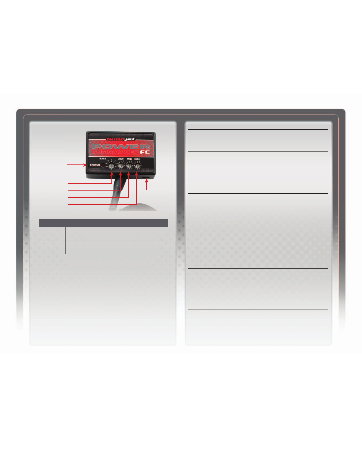
SELECTING THE MAP POSITION
The Dynojet Power Commander Fuel Controller (PCFC) comes loaded with up to ten
maps. Using a #1 Phillips screwdriver, turn the map select dial to toggle between the
loaded maps. Refer to the map position table for the maps included in your PCFC.
USING THE RPM RANGE DIALS
The Low, Mid, and High RPM Dials refer to the RPM range, in thirds, of your vehicle.
Each dial allows +/- 10% fuel adjustment on top of what fuel changes are done in the
map. With the dial facing straight up, there is no additional fuel change.
For example, if your vehicle revs to 6000 RPM:
• The low RPM dial will adjust 0-2000 RPM
• The mid RPM dial will adjust 2001-4000 RPM
• The high RPM dial will adjust 4001-6000 RPM
USING PCFC CONTROL CENTER
Take your tuning to the next level with the PCFC Control Center software.
1 Using your web browser, navigate to www.powercommander.com.
2 Click Enter Race Ready.
3 Click Downloads.
4 Click Access Downloads for Power Commander FC.
5 Click the PCFC software Download button.
6 Open the zip folder.
7 Double-click the install file and follow the on-screen instructions to install the PCFC
Control Center software. The PCFC Control Center software and maps will be
stored in C:\Program Files\PCFC Control Center.
8 Return to the Downloads or Home page where you can enter the make, model, and
year of your bike to check for and download additional maps.
LOADING ADDITIONAL MAPS
1 Connect the USB cable from the computer to the PCFC. Verify the cable is fully
seated in the PCFC.
2 Run the Control Center software by double-clicking the program icon installed on
your desktop or on your start menu.
3 Click Open Map File and select a map file.
4 Click Send Map. You can send the map to any of the ten map positions.
ALTERING MAPS USING SOFTWARE
The values in the map represent a percentage of fuel change over stock. A value of 10 in
the map indicates at that throttle position and RPM range the vehicle will be 10% richer
than stock. If the value is -10, then it would be 10% leaner than stock. You have the
ability to fine tune your fuel curve by altering these values. The Control Center software
allows a value of +250 to -100 in each cell.
USB Port
HIGH RPM Dial
MID RPM Dial
LOW RPM Dial
MAP Select
STATUS Light
Position Note
Position 1
2009-2015 Yamaha XV950
Stock exhaust
Stock air filter
Position 2
2014-2017 Yamaha Bolt 950 & SCR950
Stock exhaust
Stock air filter
Page 3

IFC22035 www.powercommander.com 2009-2017Yamaha XV950, Bolt 950, & SCR950 - 3
1 Remove the seat.
2 Remove the fuel tank.
3 Remove both side covers beneath the seat.
4 Loosen the ECM strap and lift the ECM out of place to access the battery.
5 Attach the ground wire from the PCFC to the negative side of the battery.
6 Reinstall the ECM back into place.
7 Using the supplied velcro, secure the PCFC to the top of the ECM.
Make sure to clean both surfaces with the alcohol swab before attaching.
Note: You can also secure the PCFC module under the stock ECM strap.
8 Route the PCFC harness forward going under the frame tubes directly under
the seat, then upward along the backbone of the frame towards the engine.
FIG.A
FIG.B
FIG.C
ground
Page 4

IFC22035 www.powercommander.com 2009-2017Yamaha XV950, Bolt 950, & SCR950 - 4
9 Unplug the stock wiring harness from the front and rear cylinder fuel injectors.
The front and rear cylinder fuel injectors are located directly on top of the
intake manifold.
10 Attach the PCFC connectors with the orange wires to the front cylinder fuel
injector and stock wiring harness.
11 Attach the PCFC connectors with the yellow wires to the rear cylinder fuel
injector and stock wiring harness.
12 Unplug the Throttle Position Sensor (TPS) connector.
The TPS connector is located on the rear of the throttle bodies.
FIG.D
FIG.E
FIG.F
rear
front
TPS
Page 5

IFC22035 www.powercommander.com 2009-2017Yamaha XV950, Bolt 950, & SCR950 - 5
13 Attach the connectors from the PCFC to the TPS and stock wiring harness.
14 Unplug the stock O2 sensor connections.
The O2 sensor connector is located just in front of the pivot shaft of the swing
arm on the right side of the bike. You can trace the wires from the stock O2
sensor (in the exhaust) to this connector.
15 Attach the connectors from the PCFC to the stock O2 sensor and wiring
harness.
To utilize the O2 control feature of the PCFC, the stock O2 sensor must
remain in the exhaust and active.
16 Replace the side covers.
17 Replace the fuel tank.
18 Replace the seat.
FIG.G
FIG.H
FIG.I
Page 6

IFC22035 www.powercommander.com 2009-2017Yamaha XV950, Bolt 950, & SCR950 - 6
The PCFC for this model controls the stock closed loop area. This area is
represented by the highlighted cells. The PCFC is designed to achieve a target AFR
of 13.6:1. To use this PCFC you must retain your stock O2 sensor.
It is not recommended to alter the values in the highlighted area unless instructed to
do so by a Dynojet technician.
The closed loop range can be adjusted from the PCFC software by going to Device
Tools -> Closed Loop Adjustment. In this window you can use the slider bars to
enrichen/enlean the closed loop range. We do not recommend an adjustment
beyond +/- 20.
FIG.J
 Loading...