

Page 1
Page 2

©2004 Dynojet Research, Inc. All Rights Reserved.
Flow Meter User Guide
This manual is copyrighted by Dynojet Research, Inc., hereafter referred to as Dynojet,
and all rights are reserved. This manual, as well as the software described in it, is
furnished under license and may only be used or copied in accordance with the terms of
such license. This manual is furnished for informational use only, is subject to change
without notice, and should not be construed as a commitment by Dynojet. Dynojet
assumes no responsibility or liability for any error or inaccuracies that may appear in this
manual. Except as permitted by such license, no part of this manual may be reproduced,
stored in a retrieval system, or transmitted, in any form or by any means, electronic,
mechanical, recording, or otherwise, without the prior written permission of Dynojet.
The Dynojet logo is a trademark of Dynojet Research, Inc.
Any trademarks, trade names, service marks, or service names owned or registered by any
other company and used in this guide are the property of their respective companies.
Dynojet Research, Inc., 2191 Mendenhall Drive, North Las Vegas, Nevada 89081, USA.
Printed in USA.
Part Number: 98129104 Version 01 (12/04)
Page 3

T
ABLE OF
C
ONTENTS
Flow Meter Testing
Introduction . . . . . . . . . . . . . . . . . . . . . . . . . . . . . . . . . . . . . . . . . . . . . . . . . . . . 2
Warnings . . . . . . . . . . . . . . . . . . . . . . . . . . . . . . . . . . . . . . . . . . . . . . . . . . . . . 2
Conventions Used In This Manual . . . . . . . . . . . . . . . . . . . . . . . . . . . . . . . . . . 2
Technical Support . . . . . . . . . . . . . . . . . . . . . . . . . . . . . . . . . . . . . . . . . . . . . . 2
Flow Meter Testing . . . . . . . . . . . . . . . . . . . . . . . . . . . . . . . . . . . . . . . . . . . . . . . 3
Assembling the Flow Meter . . . . . . . . . . . . . . . . . . . . . . . . . . . . . . . . . . . . . . . 4
Flow Meter Test Points . . . . . . . . . . . . . . . . . . . . . . . . . . . . . . . . . . . . . . . . . . 5
Removing the Pump Head Service Cover . . . . . . . . . . . . . . . . . . . . . . . . . . . . . 6
Checking Test Point One—Overall System Flow . . . . . . . . . . . . . . . . . . . . . . . 7
Checking Test Point Two—Filter Flow . . . . . . . . . . . . . . . . . . . . . . . . . . . . . . . 8
Checking Test Point Three—Pump Inlet Port, Sensor Side . . . . . . . . . . . . . . . 10
Checking Test Point Four—Left Outflow . . . . . . . . . . . . . . . . . . . . . . . . . . . . 12
Checking Test Point Five—Right Outflow . . . . . . . . . . . . . . . . . . . . . . . . . . . 13
Interpreting Your Flow Meter Results . . . . . . . . . . . . . . . . . . . . . . . . . . . . . . . 14
Replacing the Pump Head Service Cover . . . . . . . . . . . . . . . . . . . . . . . . . . . . 15
Data Tables . . . . . . . . . . . . . . . . . . . . . . . . . . . . . . . . . . . . . . . . . . . . . . . . . . 16
Flow Meter User Guide
i
Page 4

Page 5

F
LOW
M
ETER
T
ESTING
This document provides instructions for performing flow meter tests on your
air/fuel ratio pump (air pump). To ensure safety and accuracy in the procedures,
perform the procedures as they are described.
Document Part Number: 98129104
Vers ion 1
Last Updated: 12-30-04
Flow Meter User Guide
1
Page 6
FLOW METER
Introduction
INTRODUCTION
. . . . . . . . . . . . . . . . . . . . . . . . . . . . . . . . . . .
Flow Meter testing is a valuable troubleshooting tool. Testing with the flow meter will
help you determine if you need to rebuild the air pump. Be sure to read and follow all
warnings found throughout this manual.
For more detailed information on the air pump, refer to the Air Fuel Ratio Module
Installation and User Guide (P/N 98295110).
WARNINGS
The sensor and the copper sample tube are hot. Before touching the sensor or
the sample tube, make sure it has cooled.
The sensor is not covered by a warranty. Be sure to read and understand the Air
Fuel Ratio Module Installation and User manual.
CONVENTIONS USED IN THIS MANUAL
The conventions used in this manual are designed to protect both the user and the
equipment.
example of convention description
The Caution icon indicates a potential hazard to the
dynamometer equipment. Follow all procedures
exactly as they are described and use care when
performing all procedures.
The Warning icon indicates potential harm to the
person performing a procedure and/or the
dynamometer equipment.
TECHNICAL SUPPORT
For assistance, please contact Dynojet Technical Support at 1-800-992-3525, or write
to Dynojet Research at 2191 Mendenhall Drive, North Las Vegas, NV 89081.
Visit us on the World Wide Web at www.dynojet.com where Dynojet provides state of
the art technical support, on-line shopping, 3D visualizations, and press releases
about our latest product line.
2
Flow Meter User Guide
Page 7
FLOW METER TESTING
. . . . . . . . . . . . . . . . . . . . . . . . . . . . . . . . . . .
This section describes the five test point procedures using the flow meter to test the
air pump.
• Test Point One—Overall System Flow, page 7
• Test Point Two—Filter Flow, page 8
• Test Point Three—Pump Inlet Port, Sensor Side, page 10
• Test Point Four—Left Outflow, page 12
• Test Point Five—Right Outflow, page 13
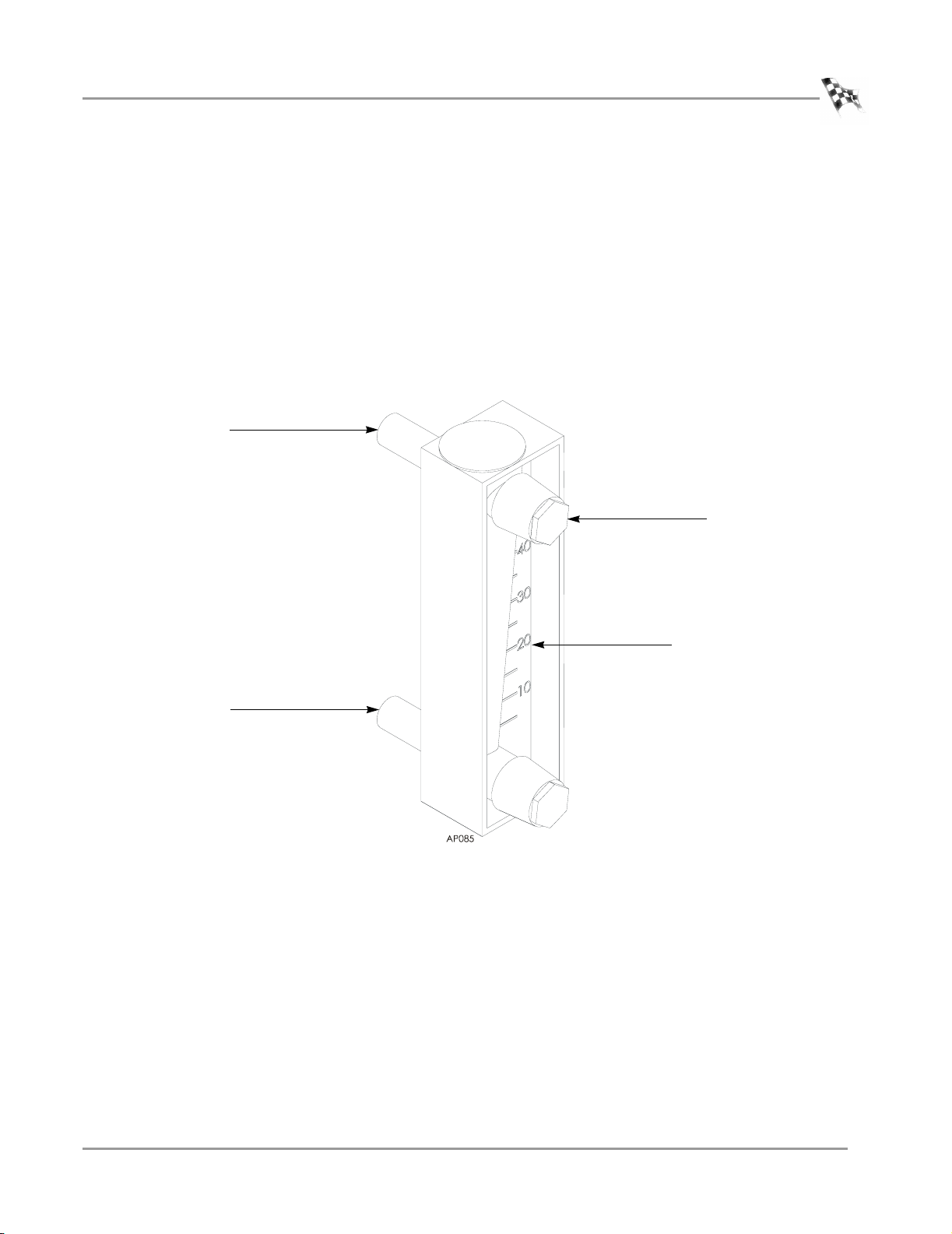
top port
USER GUIDE
Flow Meter Testing
plug
bottom port
liters/minute
Figure 1: Flow Meter
Vers ion 1 Flow Meter User Guide
3
Page 8

FLOW METER
Flow Meter Testing
ASSEMBLING THE FLOW METER
Before performing any tests on the air pump you will need to assemble the flow
meter. Everything you need to correctly assemble the flow meter is included with
your flow meter kit (P/N 34803001).
1 Knead the bag containing the o-rings and the lubricant until all three o-rings are
coated.
Note: Be careful not to stretch or tear the o-rings.
2 Place an o-ring on each plug.
3 Secure both plugs to the flow meter using the black circular installation tool.
Note: To secure the plugs, turn the tool counter-clockwise torquing to less than
three inches/pound.
o-ring
plug
4
Flow Meter User Guide
o-ring
plug
Figure 2: Assembling the Flow Meter
Page 9

Flow Meter Testing
FLOW METER TEST POINTS
The following table describes the flow meter readings for a new, rebuilt, or dirty
air pump in liters/minute. Perform all of the tests outlined in this manual and fill
out your results in the data tables on page 16. When you have completed all of the
tests, compare your results with the following table. If the flow meter reading is
equal to or lower than the dirty air pump reading, follow the steps outlined in the
action required column of the table. Pump head rebuild kits (P/N 79190003) are
available from Dynojet. Refer to the Air Fuel Ratio Module Installation and User
Guide (P/N 98295110) for rebuild instructions.
Note: If at any test point, the ball in the flow meter bounces erratically
(+/- 20L/min.) the pump heads need to be rebuilt. Pump head rebuild kits
(P/N 79190003) are available from Dynojet. Refer to the Air Fuel Ratio Module
Installation Guide (P/N 98295110) for rebuild instructions.
new or rebuilt
test point
test point one 35 25 or less rebuild pump heads
test point two 28 25 or less clean or replace filter
test point two—filter
assembly
test point three 28 25 or less rebuild pump heads
test point three—sensor
block assembly
test point four 30 25 or less rebuild pump heads
test point five 30 25 or less rebuild pump heads
pump dirty pump action required
less than 2 greater than 2 clean and tighten filter
housing
less than 2 greater than 2 clean and tighten sensor
USER GUIDE
Vers ion 1 Flow Meter User Guide
5
Page 10

FLOW METER
Flow Meter Testing
REMOVING THE PUMP HEAD SERVICE COVER
You will need to remove the pump head service cover before you can perform certain
tests with the flow meter. It is not necessary to remove the sensor when you remove
the service cover, but exercise extreme caution when handling and working near the
sensor.
The sensor is not covered by a warranty. The sensor is extremely fragile. Use
caution when handling it.
The sensor is hot. Before touching the sensor make sure it has cooled.
1 Remove the four No. 2 phillips head screws securing the pump head service
cover.
2 Remove the cover, gently flipping the cover over the sensor.
sensor
screw
pump head service cover
6
Flow Meter User Guide
Figure 3: Removing the Pump Head Service Cover
Page 11

CHECKING TEST POINT ONE—OVERALL SYSTEM FLOW
The first test point checks the flow into the entire system.
Note: Always keep the flow meter upright when testing.
1 Attach the exhaust inlet hose to the top port of the flow meter.
2Turn the air pump on.
3 Record the flow meter reading in a data table on page 16.
4Turn the air pump off.
USER GUIDE
Flow Meter Testing
exhaust inlet hose
top port
Figure 4: Test Point One—Overall System Flow
Vers ion 1 Flow Meter User Guide
7
Page 12

FLOW METER
Flow Meter Testing
CHECKING TEST POINT TWO—FILTER FLOW
Test point two is comprised of two tests. The first part of this test checks the air flow
in the entire system except for the filter assembly. The second part of this test checks
the filter assembly for leaks.
AIR FLOW
1 Remove the sensor hose from the filter.
2 Attach the end of the sensor hose to the top port of the flow meter.
3 Attach the short hose, included with your flow meter kit, to the bottom port of the
flow meter.
4 Attach the other end of the short hose to the open fitting on the filter bowl.
Note: The sensor hose was attached to this fitting.
5Turn the air pump on.
6 Record the flow meter reading in a data table on page 16.
If the flow between test point one and test point two is significantly different
(>5L/min.) the filter needs to be cleaned or replaced.
7Turn the air pump off.
sensor hose
(included with the flow meter)
8
Flow Meter User Guide
filter fitting
short hose
filter
flow meter
Figure 5: Test Point Two—Air Flow
Page 13

FILTER ASSEMBLY
1 Remove the filter bowl hose from the filter bowl.
2 Plug the filter bowl fitting with your finger.
3 Plug the exhaust inlet hose with your finger.
4Turn the air pump on.
5 Record the flow meter reading in a data table on page 16.
Note: The flow meter reading should be zero. If the flow is more than
two liters/minute the filter bowl has a significant leak.
6Turn the air pump off.
7 If the filter has a leak, clean and tighten all fittings and test again.
8 Remove the short hose from the filter fitting and the flow meter.
9 Attach the sensor hose to the filter.
10 Attach the filter bowl hose to the filter bowl.
USER GUIDE
Flow Meter Testing
sensor hose
exhaust inlet hose
plug with finger
filter bowl fitting
plug with finger
filter bowl hose
Figure 6: Test Point Two—Filter Assembly
Vers ion 1 Flow Meter User Guide
9
Page 14

FLOW METER
Flow Meter Testing
CHECKING TEST POINT THREE—PUMP INLET PORT, SENSOR SIDE
Test point three tests between the sensor block and the inlet port on the pump head.
The first part of test point three checks the flow through the filter and the sensor
block and the second part of test point three checks the sensor and sensor block for
leaks.
FILTER FLOW
1 Remove the pump inlet hose from the pump.
Note: The pump inlet hose is the wider hose inside the air pump.
2 Attach the pump inlet hose to the bottom port of the flow meter.
3 Attach the short hose, included with your flow meter kit, to the top port of the
flow meter.
4 Attach the other end of the short hose to the pump inlet port.
5Turn the air pump on.
6 Record the flow meter reading in a data table on page 16.
7Turn the air pump off.
short hose
top port
bottom port
pump inlet port
pump inlet hose
Figure 7: Test Point Three—Filter Flow
10
Flow Meter User Guide
Page 15

USER GUIDE
Flow Meter Testing
SENSOR BLOCK ASSEMBLY
The sensor is not covered by a warranty. The sensor is extremely fragile. Use
caution when handling it.
The sensor is hot. Before touching the sensor make sure it has cooled.
1 With the flow meter still attached, remove the sensor hose from the filter.
2 Plug the sensor hose with your finger.
3Turn the air pump on.
4 Record the flow meter reading in a data table on page 16.
Note: The flow meter reading should be zero. If the flow is more than
two liters/minute the sensor has a significant leak.
5Turn the air pump off.
6 If the sensor is leaking, remove the sensor and clean all threads. Clean and
tighten all fittings. Reinstall the sensor and test again.
7 Attach the pump inlet hose to the pump inlet port.
8 Attach the sensor hose to the filter.
sensor
sensor hose
plug with finger
Figure 8: Test Point Three—Sensor Block Assembly
Vers ion 1 Flow Meter User Guide
11
Page 16

FLOW METER
Flow Meter Testing
CHECKING TEST POINT FOUR—LEFT OUTFLOW
Testing the outflow allows you to determine the efficiency of the left pump head.
1 Remove the left outflow hose from the left outflow catch bottle.
2 Attach the left outflow hose to the bottom port of the flow meter.
3Turn the air pump on.
4 Record the flow meter reading in a data table on page 16.
If the flow meter reading is below the testing range, rebuild the pump head.
Pump head rebuild kits (P/N 79190003) are available from Dynojet.
Note: Dynojet recommends rebuilding both pump heads at the same time.
5Turn the air pump off.
6 Replace the left outflow hose into the left outflow catch bottle.
outflow hose
bottom port
left side of air pump
looking from the bottle
side
right side of air pump
looking from the
bottle side
catch bottle
12
Flow Meter User Guide
Figure 9: Test Point Four—Left Outflow
Page 17

CHECKING TEST POINT FIVE—RIGHT OUTFLOW
Testing the outflow allows you to determine the efficiency of the right pump head.
1 Remove the right outflow hose from the right outflow catch bottle.
2 Attach the right outflow hose to the bottom port of the flow meter.
3Turn the air pump on.
4 Record the flow meter reading in a data table on page 16.
If the flow meter reading is below the testing range, rebuild the pump head.
Pump head rebuild kits (P/N 79190003) are available from Dynojet.
Note: Dynojet recommends rebuilding both pump heads at the same time.
5Turn the air pump off.
6 Replace the right outflow hose into the right outflow catch bottle.
left side of air pump
looking from the
bottle side
USER GUIDE
Flow Meter Testing
right side of air pump
looking from the
bottle side
catch bottle
outflow hose
bottom port
Figure 10: Test Point Five—Right Outflow
Vers ion 1 Flow Meter User Guide
13
Page 18

FLOW METER
Flow Meter Testing
INTERPRETING YOUR FLOW METER RESULTS
The results from the flow meter tests indicate what maintenance needs to be
performed on the air pump. Refer to the following table to evaluate the test results. If
the flow meter reading is equal to or lower than the dirty air pump reading, follow the
steps outlined in the action required column of the table. Pump head rebuild kits (P/N
79190003) are available from Dynojet. Refer to the Air Fuel Ratio Module Installation
Guide (P/N 98295110) for rebuild instructions.
Note: Before replacing the pump head service cover be sure to perform any
necessary maintenance procedures.
new or rebuilt
test point
test point one 35 25 or less rebuild pump heads
test point two 28 25 or less clean or replace filter
test point two—filter
assembly
test point three 28 25 or less rebuild pump heads
test point three—sensor
block assembly
test point four 30 25 or less rebuild pump heads
test point five 30 25 or less rebuild pump heads
pump dirty pump action required
less than 2 greater than 2 clean and tighten filter
housing
less than 2 greater than 2 clean and tighten sensor
14
Flow Meter User Guide
Page 19

REPLACING THE PUMP HEAD SERVICE COVER
Before replacing the pump head service cover be sure to perform any necessary
maintenance procedures.
The sensor is not covered by a warranty. The sensor is extremely fragile. Use
caution when handling it.
The sensor is hot. Before touching the sensor make sure it has cooled.
1 Carefully flip the pump head service cover back over the sensor.
2 Secure the pump head service cover using the four No. 2 phillips head screws
removed earlier.
USER GUIDE
Flow Meter Testing
screw
pump head
service cover
sensor
Figure 11: Replacing the Pump Head Service Cover
Vers ion 1 Flow Meter User Guide
15
Page 20

FLOW METER
Flow Meter Testing
DATA TABLES
Use these tables to keep a record of your flow meter readings. Compare your results
with the table on page 14.
test point flow meter readings
1
2(a)
2(b)
3(a)
3(b)
4
5
test point flow meter readings
1
2(a)
2(b)
3(a)
3(b)
4
5
16
Flow Meter User Guide
test point flow meter readings
1
2(a)
2(b)
3(a)
3(b)
4
5
Page 21

Page 22

 Loading...