

Page 1
2014 Honda CB650F/CBR650F - PCFC - 1FC16052 www.powercommander.com
Installation Instructions
PLEASE READ ALL DIRECTIONS BEFORE STARTING INSTALLATION
THE IGNITION MUST BE TURNED
OFF BEFORE INSTALLATION!
THE LATEST PCFC CONTROL CENTER
SOFTWARE AND MAP FILES CAN BE
DOWNLOADED FROM OUR WEB SITE AT:
www.powercommander.com
2191 Mendenhall Drive North Las Vegas, NV 89081 (800) 992-4993 www.powercommander.com
2014 Honda CB650F/CBR650F
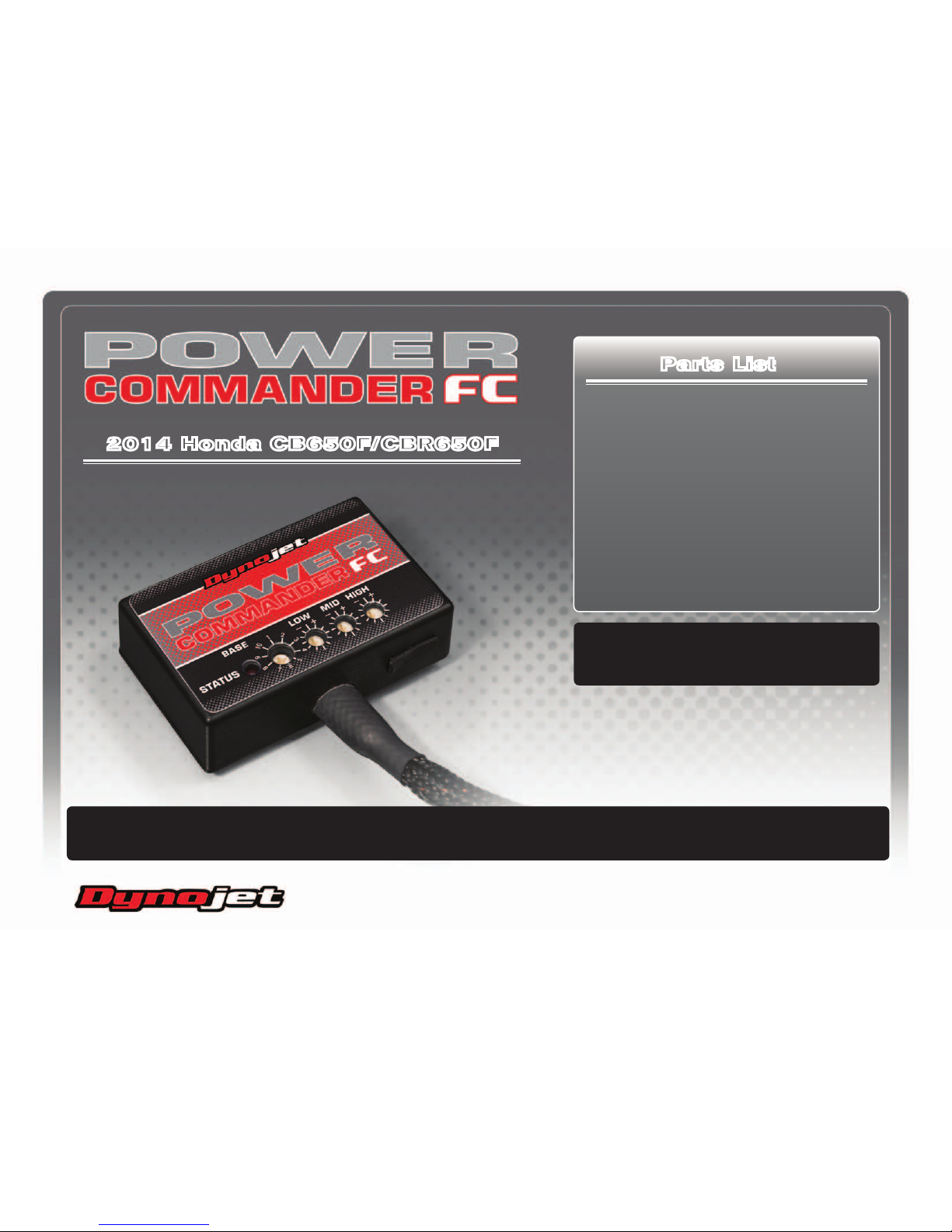
1 Power Commander FC
1 USB Cable
1 Installation Guide
2 Dynojet Decals
2 Velcro strips
1 Alcohol swab
1 O2 Optimizer
Parts List
Page 2

FC16052 www.powercommander.com 2014 Honda CB650F/CBR650F - PCFC - 2
SELECTING THE MAP POSITION
The Dynojet Power Commander Fuel Controller (PCFC) comes loaded with up to ten
maps. Using a #1 Phillips screwdriver, turn the map select dial to toggle between the
loaded maps. Refer to the map position table for the maps included in your PCFC.
USING THE RPM RANGE DIALS
The Low, Mid, and High RPM Dials refer to the RPM range, in thirds, of your vehicle.
Each dial allows +/- 10% fuel adjustment on top of what fuel changes are done in the
map. With the dial facing straight up, there is no additional fuel change.
For example, if your vehicle revs to 6000 RPM:
• The low RPM dial will adjust 0-2000 RPM
• The mid RPM dial will adjust 2001-4000 RPM
• The high RPM dial will adjust 4001-6000 RPM
USING PCFC CONTROL CENTER
Take your tuning to the next level with the PCFC Control Center software.
1 Using your web browser, navigate to www.powercommander.com.
2 Click Enter Race Ready.
3 Click Downloads.
4 Click Access Downloads for Power Commander FC.
5 Click the PCFC software Download button.
6 Open the zip folder.
7 Double-click the install file and follow the on-screen instructions to install the PCFC
Control Center software. The PCFC Control Center software and maps will be
stored in C:\Program Files\PCFC Control Center.
8 Return to the Downloads or Home page where you can enter the make, model, and
year of your bike to check for and download additional maps.
LOADING ADDITIONAL MAPS
1 Connect the USB cable from the computer to the PCFC. Verify the cable is fully
seated in the PCFC.
2 Run the Control Center software by double-clicking the program icon installed on
your desktop or on your start menu.
3 Click Open Map File and select a map file.
4 Click Send Map. You can send the map to any of the ten map positions.
ALTERING MAPS USING SOFTWARE
The values in the map represent a percentage of fuel change over stock. A value of 10 in
the map indicates at that throttle position and RPM range the vehicle will be 10% richer
than stock. If the value is -10, then it would be 10% leaner than stock. You have the
ability to fine tune your fuel curve by altering these values. The Control Center software
allows a value of +250 to -100 in each cell.
USB Port
HIGH RPM Dial
MID RPM Dial
LOW RPM Dial
MAP Select
STATUS Light
Position Note
Position 1
2014 Honda CB650F/CBR650F
Stock exhaust
Stock air filter
Page 3

FC16052 www.powercommander.com 2014 Honda CB650F/CBR650F - PCFC - 3
1 Remove the seat.
2 Remove both side panels below the seat. Remove the mid and lower fairing
panels on both sides. Remove the inner fairing panels just forward of the fuel
tank on both sides (Fig. A).
3 Loosen the front of the fuel tank. Lift and prop the fuel tank.
4 Using the supplied Velcro, secure the PCFC module in the tail section just rear
of the bike’s battery (Fig. B).
Clean both surfaces with the supplied alcohol swab prior to applying the
Velcro adhesive.
5 Route the PCFC wiring harness forward along the left side frame rail and
under any frame cross-members.
6 Secure the PCFC ground wire with the small ring lug to the negative (-)
terminal of the bike’s battery.
7 Locate and unplug the Fuel Injector sub-harness connector just below the fuel
tank on the left side of the bike (Fig. C).
This is a BLACK 6-pin connector.
FIG.A
FIG.B
FIG.C
Remove
Remove
Remove
Remove
Remove
Ground
PCFC harness
Unplug
Page 4

FC16052 www.powercommander.com 2014 Honda CB650F/CBR650F - PCFC - 4
8 Plug the PCFC wiring harness in-line of the stock Fuel Injector sub-harness
connectors (Fig. D).
9 Route the pair of 3-pin PCFC wiring harness connectors along the left side of
the airbox, between the airbox and the frame, and to the bike’s Throttle Position
Sensor on the left hand side of the throttle bodies.
10 At the left hand side of the throttle bodies, unplug the stock wiring harness
from the bike’s Throttle Position Sensor (Fig. E).
11 Plug the PCFC wiring harness in-line of the bike’s TPS and the stock wiring
harness (Fig. F).
FIG.D
FIG.E
FIG.F
Unplug
Page 5

FC16052 www.powercommander.com 2014 Honda CB650F/CBR650F - PCFC - 5
FIG.G
12 From the left hand side of the bike, locate and unplug the stock connector for
the bike’s O2 sensor (Fig. J).
This is a BLACK 4-pin connector. It is rear of the engine. You can trace the
cable from the stock O2 sensor in the exhaust to it.
13 Plug the supplied O2 Optimizer into the bike’s wiring harness in-place of the
stock O2 sensor (Fig. K).
The stock O2 sensor will no longer be used. It can be removed from the
exhaust if desired and if you have a way to plug the hole in the exhaust.
14 Lower and secure the fuel tank. Reinstall the bodywork and seats.
FIG.H
Unplug
O2 Optimizer
 Loading...