

Page 1

Page 2

©2015 Dynojet Research, Inc. All Rights Reserved.
Torque Cell Installation Guide for Model 250i/250iP DynoWare RT Dynamometers.
This manual is copyrighted by Dynojet Research, Inc., hereafter referred to as Dynojet,
and all rights are reserved. This manual, and the software described in it, is furnished
under license and may only be used or copied in accordance with the terms of such license.
This manual is furnished for informational use only, is subject to change without notice,
and should not be construed as a commitment by Dynojet. Dynojet assumes no
responsibility or liability for any error or inaccuracies that may appear in this manual.
Except as permitted by such license, no part of this manual may be reproduced, stored in a
retrieval system, or transmitted, in any form or by any means, electronic, mechanical,
recording, or otherwise, without the prior written permission of Dynojet.
The Dynojet logo is a trademark of Dynojet Research, Inc.
Any trademarks, trade names, service marks, or service names owned or registered by any
other company and used in this guide are the property of their respective companies.
Dynojet Research, Inc., 2191 Mendenhall Drive, North Las Vegas, Nevada 89081, USA.
Printed in USA.
Part Number: 98200070 Version 2 (07/2015)
Page 3

T
Chapter 1 Torque Cell Installation
Introduction . . . . . . . . . . . . . . . . . . . . . . . . . . . . . . . . . . . . . . . . . . . . . . . . . . . . . . . . . . . . 1-2
Conventions Used In This Manual . . . . . . . . . . . . . . . . . . . . . . . . . . . . . . . . . . . . . . . 1-2
Technical Support . . . . . . . . . . . . . . . . . . . . . . . . . . . . . . . . . . . . . . . . . . . . . . . . . . . . 1-2
Main Dyno Power . . . . . . . . . . . . . . . . . . . . . . . . . . . . . . . . . . . . . . . . . . . . . . . . . . . . . . . 1-3
Connecting and Disconnecting the Power—Above Ground Dyno . . . . . . . . . . . . 1-3
Connecting and Disconnecting the Power—In Ground Dyno . . . . . . . . . . . . . . . . 1-4
Accessing the Dyno . . . . . . . . . . . . . . . . . . . . . . . . . . . . . . . . . . . . . . . . . . . . . . . . . . . . . 1-5
Accessing the Dyno—Above Ground . . . . . . . . . . . . . . . . . . . . . . . . . . . . . . . . . . . . 1-5
Accessing the Dyno—In Ground . . . . . . . . . . . . . . . . . . . . . . . . . . . . . . . . . . . . . . . . 1-8
Load Cell Installation . . . . . . . . . . . . . . . . . . . . . . . . . . . . . . . . . . . . . . . . . . . . . . . . . . . . 1-9
Routing the Load Cell Cable . . . . . . . . . . . . . . . . . . . . . . . . . . . . . . . . . . . . . . . . . . . . 1-12
Routing the Load Cell Cable—Above Ground Dyno . . . . . . . . . . . . . . . . . . . . . . . 1-12
Routing the Load Cell Cable—In Ground Dyno . . . . . . . . . . . . . . . . . . . . . . . . . . . 1-13
Replacing the Covers . . . . . . . . . . . . . . . . . . . . . . . . . . . . . . . . . . . . . . . . . . . . . . . . . . 1-14
Replacing the Covers—Above Ground Dyno . . . . . . . . . . . . . . . . . . . . . . . . . . . . . 1-14
Replacing the Cover—In Ground Dyno . . . . . . . . . . . . . . . . . . . . . . . . . . . . . . . . . . 1-17
Chapter 2 Load Cell Calibration
ABLE OF
C
ONTENTS
Load Cell Calibration . . . . . . . . . . . . . . . . . . . . . . . . . . . . . . . . . . . . . . . . . . . . . . . . . . . . 2-2
Torque Cell Installation Guide for Model 250i/250iP DynoWare RT Dynamometers
i
Page 4

Page 5

C HAPTER 1
The torque cell along with Dynojet Power Core software provides the technician with
the ability to control vehicle RPM or speed at any throttle opening. Through our
exclusive closed-loop software design, the vehicle is automatically held at your predetermined setting. Use the torque cell and Power Core software to measure re al-time
torque, and perform sweep, step and custom load simulation tests.
This document provides instructions for installing the torque cell on a Dynojet
Model 250i/250iP DynoWare RT Motorcycle Dynamometer (dyno) and calibrating
the torque cell using Power Core software. To ensure safety and accuracy in the
procedures, perform the procedures as they are described.
Document Part Number: 98200070
Version 2
Last Updated: 07-01-2015
T
ORQUE
C
ELL INSTALLATION
This chapter is divided into the following categories:
• Introduction, page 1-2
• Main Dyno Power, page 1-3
• Accessing the Dyno, page 1-5
• Load Cell Installation, page 1-9
• Routing the Load Cell Cable, page 1-12
• Replacing the Covers, page 1-14
Torque Cell Installation Guide for Model 250i/250iP DynoWare RT Dynammometers
1-1
Page 6

CHAPTER 1
Introduction
Torque Cell Installation Guide for Model 250i/250iP DynoWare RT Dynammometers
1-2
INTRODUCTION
The torque cell, when added to Dynojet's market leading inertia dynamometer, results
in a complete vehicle performance test. Before installing and calibrating your torque
module, please take a moment to read this guide for installation instructions, features,
and other important information.
CONVENTIONS USED IN THIS MANUAL
The conventions used in this manual are designed to protect both the user and the
equipment.
example of convention description
The Caution icon indicates a potential hazard to the
dynamometer equipment. Follow all procedures
exactly as they are described and use care when
performing all procedures.
The Warning icon indicates potential harm to the
person performing a procedure and/or the
dynamometer equipment.
Bold Highlights items you can select on in the software
interface, including buttons and menus.
TECHNICAL SUPPORT
For assistance, please contact Dynojet Technical Support at 1-800-992-3525, or write
to Dynojet at 2191 Mendenhall Drive, North Las Vegas, NV 89081.
Visit us on the World Wide Web at www.dynojet.com where Dynojet provid es state of
the art technical support, on-line shopping, and press releases about our latest
product lines.
Page 7
TORQUE CELL INSTALLATION
Main Dyno Power
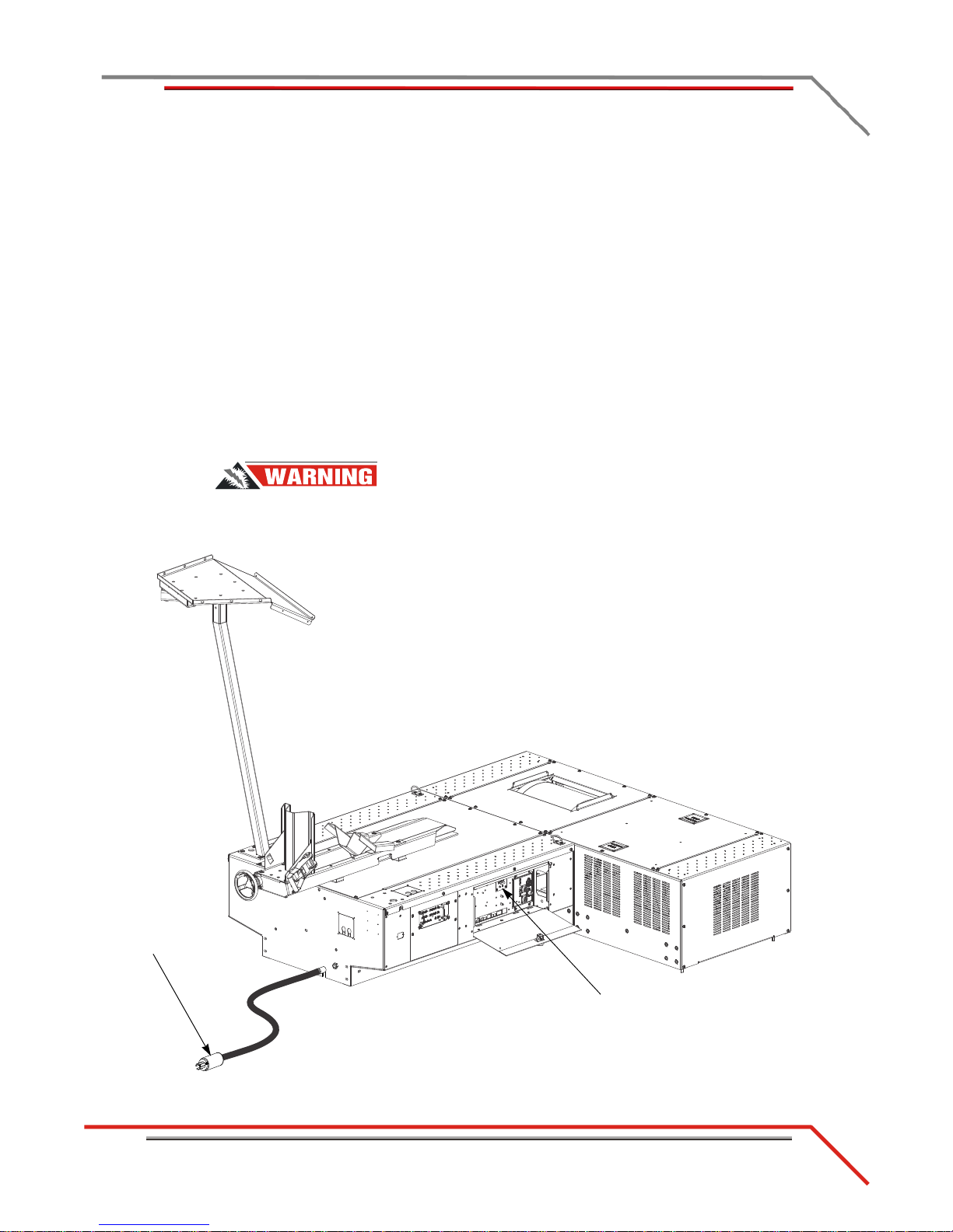
MAIN DYNO POWER
MC153
main breaker
power plug
This section describes how to connect and disconnect the power to both the above
ground and in ground dyno.
CONNECTING AND DISCONNECTING THE POWER—ABOVE GROUND DYNO
Use the following steps to connect and disconnect power to the above ground dyno.
Always turn the power off when connecting and disconnecting cables.
1 Use the main breaker to turn power on and off to the dyno.
The main breaker is located inside the CPI door. When the handle is in the down
position all power into the dyno is turned off.
2 Disconnect the power plug to ensure all power has been removed from the dyno
before performing certain installation procedures.
Components attached to and within the dynamometer operate with
potentially lethal voltages. The power cord must be disconnected from the
power source before servicing electrical components or wiring.
Version 2 Torque Cell Installation Guide for Model 250i/250iP DynoWare RT Dynammometers
Figure 1-1: Main Dyno Power—Above Ground Dyno
1-3
Page 8
CHAPTER 1
Main Dyno Power
Torque Cell Installation Guide for Model 250i/250iP DynoWare RT Dynammometers
1-4
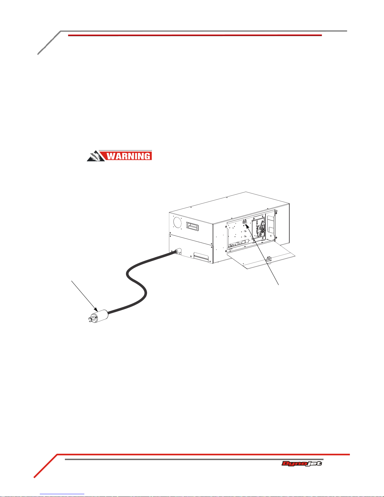
CONNECTING AND DISCONNECTING THE POWER—IN GROUND DYNO
PD231
main breaker
power plug
Use the following steps to connect and disconnect power to the in ground dyno.
Always turn the power off when connecting and disconnecting cables.
1 Use the main breaker to turn power on and off to the dyno.
The main breaker is located inside the CPI door. When the handle is in the down
position all power into the dyno is turned off.
2 Disconnect the power plug to ensure all power has been removed from the dyno
before installing the DynoWare RT electronics.
Components attached to and within the dynamometer operate with
potentially lethal voltages. The power cord must be disconnected from the
power source before servicing electrical components or wiring.
Figure 1-2: Main Dyno Power—In Ground Dyno
Page 9
TORQUE CELL INSTALLATION
Accessing the Dyno
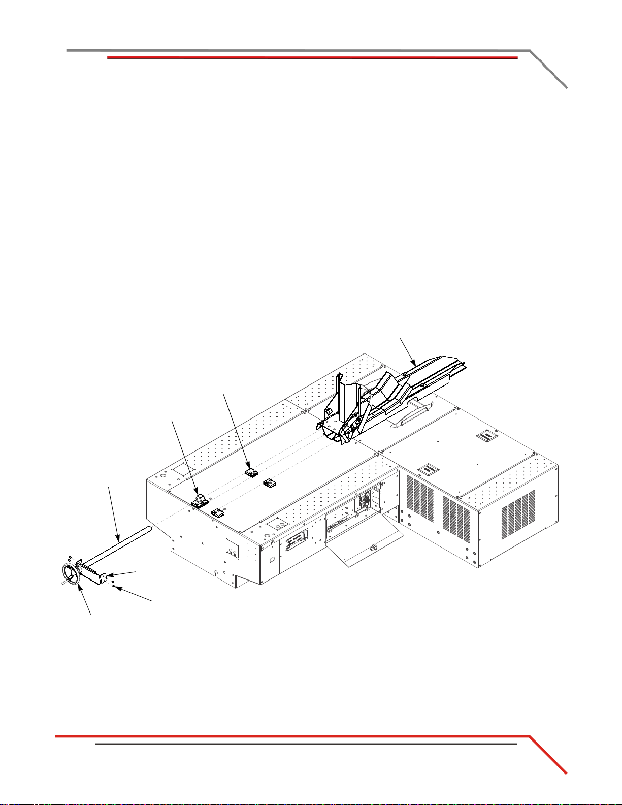
ACCESSING THE DYNO
TC080
hand wheel
carriage screw
screws
carriage clamp
tire carriage
bearing
bracket
nut block
Installing the load cell requires access to the dyno and eddy current brake. This
section will walk you through accessing both the above ground and in ground dyno.
Make sure you have disconnected the power to the dyno before removing the covers.
Refer to “Main Dyno Power” on page 1-3.
ACCESSING THE DYNO—ABOVE GROUND
You will need to remove the tire carriage, center panel, and eddy current brake top
cover in order to route the load cell cable to the eddy current brake driver.
1 Remove the four screws securing the bearing bracket to the tire carriage and set
aside.
2 Using the hand wheel, or the power carriage, unscrew the bearing brac ket and the
carriage screw and set aside.
3 Remove the tire carriage by sliding the carriage under the carriage clamps toward
the back of the dyno and set aside.
Version 2 Torque Cell Installation Guide for Model 250i/250iP DynoWare RT Dynammometers
Figure 1-3: Remove the Tire Carriage
1-5
Page 10
CHAPTER 1
Accessing the Dyno
Torque Cell Installation Guide for Model 250i/250iP DynoWare RT Dynammometers
1-6
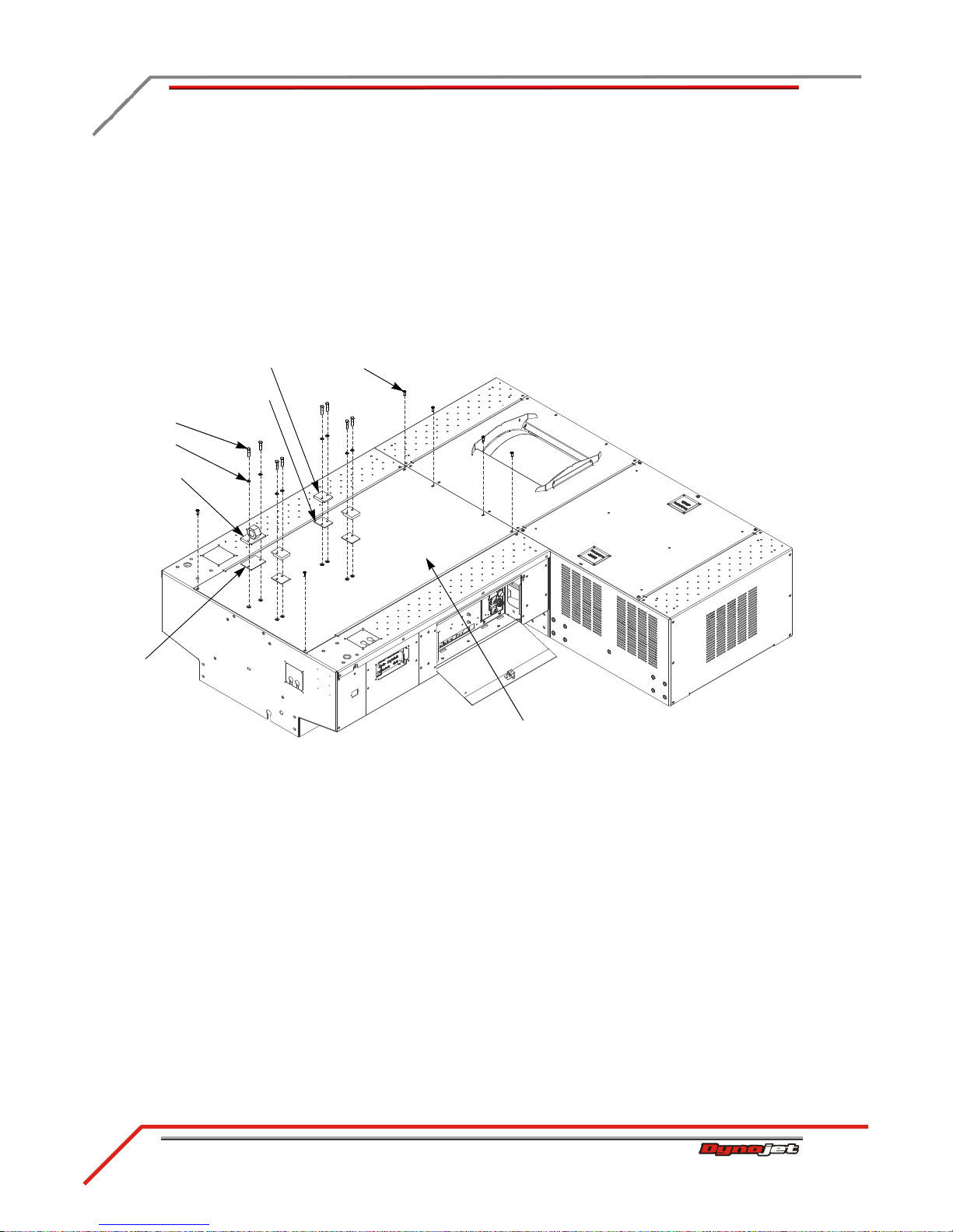
4 Remove the two 5/16-inch bolts and washers securing each of the carriage clamps
TC081
screw
center panel
carriage clamp
washer
bolt
shim
nut block
shim
and shims and set aside.
5 Remove the three carriage clamps and shims and set aside.
6 Remove the two 5/16-inch bolts and washers securing the nut block and shim and
set aside.
7 Remove the nut block and shim and set aside.
8 Remove the six 1/4-20 x 5/8-inch pan head screws securing the center panel to
the dyno carriage and set aside.
9 Remove the center panel and set aside.
Figure 1-4: Remove the Center Panel
Page 11

TORQUE CELL INSTALLATION
Accessing the Dyno
10 Remove the six screws securing the eddy current brake top cover and set aside.
brake top cover
11 Remove the brake top cover and set aside.
Figure 1-5: Remove the Brake Top Cover
Version 2 Torque Cell Installation Guide for Model 250i/250iP DynoWare RT Dynammometers
1-7
Page 12

CHAPTER 1
Accessing the Dyno
Torque Cell Installation Guide for Model 250i/250iP DynoWare RT Dynammometers
1-8
ACCESSING THE DYNO—IN GROUND
PD245
brake cover
You will need to remove the eddy current brake pit cover in order to route the load cell
cable to the eddy current brake driver.
1 Remove the four 3/8-16 x 1/8-inch button-head flange screws securing the eddy
current brake pit cover and set aside.
2 Remove the eddy current brake pit cover and set aside.
Figure 1-6: Remove the Brake Pit Cover
Page 13

TORQUE CELL INSTALLATION
Load Cell Installation
LOAD CELL INSTALLATION
bar
This section describes how to remove the existing bar on the eddy current brake and
install the load cell. Use the following instructions for both the above ground and in
ground dynos.
You will need the following part:
part description
load cell and cable, above ground
P/N 76950573
load cell and cable, in ground
P/N 76950759
1 Verify the main dyno power is disconnected. Refer to“Main Dyno Power” on page
1-3 for more information.
2 Remove the two bolts and nuts securing the existing bar on the eddy current brake
and remove the bar. Set the bolts and nuts aside.
Version 2 Torque Cell Installation Guide for Model 250i/250iP DynoWare RT Dynammometers
Figure 1-7: Remove the Existing Bar
1-9
Page 14

CHAPTER 1
Load Cell Installation
Torque Cell Installation Guide for Model 250i/250iP DynoWare RT Dynammometers
1-10
3 Verify the eyelets on the load cell are spaced the same as the bar removed earlier.
distance must be
the same
eyelet
bar
lock nut
load cell cable
load cell
Adjust the load cell spacing by loosening the lock nut and turning the eyelet.
Figure 1-8: Verify Load Cell Spacing
4 Secure the load cell to the mountin g bracket using t he two bolts and nu ts removed
earlier.
Figure 1-9: Install the Load Cell—Above Ground Dyno
Page 15

TORQUE CELL INSTALLATION
Load Cell Installation
Figure 1-10: Install the Load Cell—In Ground Dyno
PD229
install the load cell
(the brake is not
shown for clarity)
Version 2 Torque Cell Installation Guide for Model 250i/250iP DynoWare RT Dynammometers
1-11
Page 16

CHAPTER 1
Routing the Load Cell Cable
Torque Cell Installation Guide for Model 250i/250iP DynoWare RT Dynammometers
1-12
ROUTING THE LOAD CELL CABLE
load cell cable
eddy current brake driver
DynoWare RT
load cell
M158C
air hole in drum
bulkhead
Use the following instructions to identify and route the load cell cable.
cable brief routing description
76950573 load cell and cable—above ground dyno
76950759 load cell and cable—in ground dyno
connects the load cell to the eddy current brake driver
ROUTING THE LOAD CELL CABLE—ABOVE GROUND DYNO
1 Route the load cell cable from the eddy current brake through the air hole in the
drum bulkhead and over to eddy current brake driver.
Make sure the load cell cable is clear of any power cables or hot or rotating objects.
2 Attach the load cell cable to the eddy current brake driver .
3 Secure the load cell cable with a zip tie to the underside of the carriage assembly
bulkhead.
Figure 1-11: Routing the Load Cell Cable—Above Ground Dyno
Page 17

TORQUE CELL INSTALLATION
Routing the Load Cell Cable
ROUTING THE LOAD CELL CABLE—IN GROUND DYNO
load cell
route
communications
cables in designated
conduit
DynoWare RT
main module
eddy current
brake driver
control panel
interface (CPI)
air fuel ratio
module (AFR)
load cell cable
P246
D
1 Open the front panel of the CPI to access the eddy current brake driver.
2 Route the load cell cable from the eddy current brake, through the designated
communications pit conduit, and attach to the eddy current brake driver inside
the CPI.
Note: Be sure to keep the power and communications cables in different pit
conduits.
Version 2 Torque Cell Installation Guide for Model 250i/250iP DynoWare RT Dynammometers
Figure 1-12: Routing the Load Cell Cable—In Ground Dyno
1-13
Page 18

CHAPTER 1
Replacing the Covers
Torque Cell Installation Guide for Model 250i/250iP DynoWare RT Dynammometers
1-14
REPLACING THE COVERS
TC081
screw
center panel
carriage clamp
washer
bolt
shim
nut block
shim
Before replacing the covers, verify the load cell is installed and the load cell cable is
routed to the eddy current brake driver.
Before replacing the eddy current brake top cover, be sure to calibrate your load cell.
Refer to “Load Cell Calibration” on page 2-2.
REPLACING THE COVERS—ABOVE GROUND DYNO
1 Secure the center panel to the dyno carriage using the six 1/4-20 x 5/8-inch pan
head screws removed earlier.
2 Secure the nut block and shim using the two 5/16-inch bolts and washers removed
earlier.
3 Secure each carriage clamps and shim using two 5/16-inch bolts and washers
removed earlier,
Figure 1-13: Replace the Center Panel
Page 19

TORQUE CELL INSTALLATION
Replacing the Covers
4 Starting from the back of the dyno, slide the carriage under the carriage clamps.
TC080
hand wheel
carriage screw
screws
carriage clamp
tire carriage
bearing
bracket
nut block
5 Slide the carriage screw, bearing bracket, and the hand wheel t oward the nut block
until the carriage screw is touching the nut block.
6 Using the hand wheel, or the power carriage, screw the carriage through the nut
block and into the screw support bracket.
7 Secure the bearing bracket to the carriage using four screws removed earlier.
Version 2 Torque Cell Installation Guide for Model 250i/250iP DynoWare RT Dynammometers
Figure 1-14: Replace the Tire Carriage
1-15
Page 20

CHAPTER 1
Replacing the Covers
Torque Cell Installation Guide for Model 250i/250iP DynoWare RT Dynammometers
1-16
8 Secure the eddy current brake top cover using the six bolts removed earlier.
EB242
eddy current
brake cover
Note: Before replacing the eddy curren t brake top cove r, be sure to calibrate your
load cell. Refer to “Load Cell Calibration” on page 2-2.
Figure 1-15: Replace the Eddy Current Brake Top Cover
Page 21

TORQUE CELL INSTALLATION
Replacing the Covers
REPLACING THE COVER—IN GROUND DYNO
PD245
brake cover
Before replacing the eddy current brake pit cover, be sure to calibrate your load cell.
Refer to “Load Cell Calibration” on page 2-2.
Secure the eddy current brake pit cover using the four screws removed earlier.
Figure 1-16: Replace the Brake Pit Cover
Version 2 Torque Cell Installation Guide for Model 250i/250iP DynoWare RT Dynammometers
1-17
Page 22

Page 23

C HAPTER 2
This chapter will walk you through calibrating the load cell on both the above ground
and in ground dynos. To ensure safety and accuracy in the procedures, perform the
procedures as they are described.
L
OAD
C
ELL
C
ALIBRATION
Torque Cell Installation Guide for Model 250i/250iP DynoWare RT Dynamometers
2-1
Page 24

CHAPTER 2
Load Cell Calibration
Torque Cell Installation Guide for Model 250i/250iP DynoWare RT Dynamometers
2-2
LOAD CELL CALIBRATION
This section provides instructions for calibrating the load cell. Follow the direct ions on
the screen exactly. Failure to perform the directions accurately will result in improper
torque values.
You will need the following parts:
part description part description
weight, 25 pounds (4)
P/N 35430899
1 Verify the dyno is connected to power. Refer to “Main Dyno Power” on page 1-3.
2 Double-click the Power Core program icon.
3Click Dyno Control from the Application Launcher.
4 Verify you are connected to the DynoWare RT main module.
Note: For more information on connecting to the dyno electronics, refer to the
Power Core Quick Start Guide (on your Power Core CD or at www. dynojet.com) or
the Power Core Online Help.
5 From the Configuration ribbon, click Load Cell Calibration .
6 Remove the calibration arm and mass if it is installed.
7 Release the dyno brake. Make sure the drums are free to rotate.
Note: There should not be anything resting on the eddy current brake or the dyno
drum during this procedure.
8Click Next to zero the connected torque cell.
calibration arm assembly
P/N 61319001
Figure 2-1: Zero Calibration Window
Page 25

LOAD CELL CALIBRATION
Load Cell Calibration
9 Using the drop-down arrow, set the index to zero.
bolt pattern closest to
the end of the
calibration arm
bolt pattern near the
center of the
calibration arm
Note: Powersports Dynos have one load cell, leave the index set to zero.
10 Enter the calibration weight. This value is stamped into the calibration arm.
Figure 2-2: Calibration Mass Window
Enter the calibration number stamped near the bolt pattern at the end of the
calibration arm in the Mass box. If you do not have enough room to use the bolt
pattern closest to the end of the calibration arm, use the number stamped near the
bolt pattern in the center of the arm.
Note: Dynojet recommends you secure the calibration arm using the bolt pattern
closest to the end of the arm unless space constraints in your dyno room do not
allow you to.
Figure 2-3: Calibration Arm Number
Version 2 Torque Cell Installation Guide for Model 250i/250iP DynoWare RT Dynamometers
2-3
Page 26

CHAPTER 2
Load Cell Calibration
Torque Cell Installation Guide for Model 250i/250iP DynoWare RT Dynamometers
2-4
11 Install the calibration arm and weights using the bolts at the end of the calibration
T 074M
weights
weight support pin
secure arm to brake by
tightening handle
arm.
Note: If you do not have enough room to use the bolt pattern closest to the end of
the calibration arm, use the bolt pattern in the center of the arm. Refer to Figure
2-6 for above ground dynos and Figure 2-7 for in ground dynos.
11a Secure the calibration arm to the eddy current brake by tightening the bolt
using the handle.
11b Gently place the weights on the calibration arm.
Note: Verify the calibration arm is not contacting the cover.
The calibration weights are very heavy. The weights must be set on the
arm gently or you could damage the load cell.
Figure 2-4: Install the Calibration Arm and Weights Using the Bolt Pattern Closest to the End—Above Ground Dyno
Page 27

LOAD CELL CALIBRATION
Load Cell Calibration
Figure 2-5: Install the Calibration Arm and Weights Using the Bolt Pattern Closest to the End—In Ground Dyno
T076M
weights
weight support pin
secure arm to brake by
tightening handle
Version 2 Torque Cell Installation Guide for Model 250i/250iP DynoWare RT Dynamometers
2-5
Page 28

CHAPTER 2
Load Cell Calibration
Torque Cell Installation Guide for Model 250i/250iP DynoWare RT Dynamometers
2-6
If you do not have enough room to use the bolt pattern closest to the end of the
T075M
weights
weight support pin
secure arm to brake by
tightening handle
calibration arm, use the bolt pattern in the center of the arm as shown in
Figure 2-6 for above ground dynos and for Figure 2-7 in ground dynos.
Figure 2-6: Install the Calibration Arm and Weights Using the Bolt Pattern in the Center—Above Ground Dyno
Page 29

LOAD CELL CALIBRATION
Load Cell Calibration
Figure 2-7: Install the Calibration Arm and Weights Using the Bolt Pattern in the Center—In Ground Dyno
T077M
weights
weight support pin
secure arm to brake by
tightening handle
Version 2 Torque Cell Installation Guide for Model 250i/250iP DynoWare RT Dynamometers
2-7
Page 30

CHAPTER 2
Load Cell Calibration
Torque Cell Installation Guide for Model 250i/250iP DynoWare RT Dynamometers
2-8
12 With the calibration arm and weights secured, click Next to calibrate.
13 Remove the calibration arm and weights and click Finish.
Figure 2-8: Finish Calibration Window
14 Confirm the calibration was successful.
For more information refer to the Power Core Online Help.
Page 31

 Loading...