

Page 1
Page 2

©2007-2010 Dynojet Research, Inc. All Rights Reserved.
Compressed Air Air Fuel Ratio Module Installation and User Guide.
This manual is copyrighted by Dynojet Research, Inc., hereafter referred to as Dynojet,
and all rights are reserved. This manual, as well as the software described in it, is
furnished under license and may only be used or copied in accordance with the terms of
such license. This manual is furnished for informational use only, is subject to change
without notice, and should not be construed as a commitment by Dynojet. Dynojet
assumes no responsibility or liability for any error or inaccuracies that may appear in this
manual. Except as permitted by such license, no part of this manual may be reproduced,
stored in a retrieval system, or transmitted, in any form or by any means, electronic,
mechanical, recording, or otherwise, without the prior written permission of Dynojet.
The Dynojet logo is a trademark of Dynojet Research, Inc.
Any trademarks, trade names, service marks, or service names owned or registered by any
other company and used in this guide are the property of their respective companies.
Dynojet Research, Inc., 2191 Mendenhall Drive, North Las Vegas, Nevada 89031, USA.
Printed in USA.
Part Number: 98200006 Version 05 (05/2010)
Page 3

T
ABLE OF
C
ONTENTS
Chapter 1 Air Fuel Ratio Module and
Compressed Air Pump Installation
Introduction . . . . . . . . . . . . . . . . . . . . . . . . . . . . . . . . . . . . . . . . . . . . . . . . . .1-2
Warnings . . . . . . . . . . . . . . . . . . . . . . . . . . . . . . . . . . . . . . . . . . . . . . . . . .1-2
Conventions Used In This Manual . . . . . . . . . . . . . . . . . . . . . . . . . . . . . . .1-3
Technical Support . . . . . . . . . . . . . . . . . . . . . . . . . . . . . . . . . . . . . . . . . . .1-3
Air Fuel Module Installation . . . . . . . . . . . . . . . . . . . . . . . . . . . . . . . . . . . . .1-4
Installing the Air Fuel Module . . . . . . . . . . . . . . . . . . . . . . . . . . . . . . . . . .1-4
Compressed Air Pump Assembly . . . . . . . . . . . . . . . . . . . . . . . . . . . . . . . . .1-8
Compressed Air Requirements . . . . . . . . . . . . . . . . . . . . . . . . . . . . . . . . . .1-8
Setting Up the Stand Assembly . . . . . . . . . . . . . . . . . . . . . . . . . . . . . . . . .1-8
Installing the Pump Assembly on the Stand . . . . . . . . . . . . . . . . . . . . . . . .1-9
Connecting the Solenoid Power—i Series Dynos . . . . . . . . . . . . . . . . . . . 1-10
Connecting the Solenoid Power—Non i Series Dynos . . . . . . . . . . . . . . .1-10
Adjusting the Air Flow . . . . . . . . . . . . . . . . . . . . . . . . . . . . . . . . . . . . . . . 1-12
Chapter 2 Using the Air Fuel Ratio Module
Module and Pump Set Up . . . . . . . . . . . . . . . . . . . . . . . . . . . . . . . . . . . . . .2-2
Sample and View Air Fuel Ratios . . . . . . . . . . . . . . . . . . . . . . . . . . . . . . . . .2-3
Sampling Air Fuel Ratios . . . . . . . . . . . . . . . . . . . . . . . . . . . . . . . . . . . . . . .2-3
Viewing and Graphing Air/Fuel Runs . . . . . . . . . . . . . . . . . . . . . . . . . . . . .2-5
Air Pump Maintenance and Troubleshooting . . . . . . . . . . . . . . . . . . . . . . .2-7
Sensor Information . . . . . . . . . . . . . . . . . . . . . . . . . . . . . . . . . . . . . . . . . .2-7
Correcting Lean Air Fuel Readings . . . . . . . . . . . . . . . . . . . . . . . . . . . . . . .2-7
Pump Maintenance—Stand Alone . . . . . . . . . . . . . . . . . . . . . . . . . . . . . . .2-8
Pump Maintenance—On Dyno . . . . . . . . . . . . . . . . . . . . . . . . . . . . . . . . .2-9
Appendix A On-Board Dyno Installation
Installation . . . . . . . . . . . . . . . . . . . . . . . . . . . . . . . . . . . . . . . . . . . . . . . . . . .A-2
Compressed Air Requirements . . . . . . . . . . . . . . . . . . . . . . . . . . . . . . . . . .A-2
Installing the Pump Assembly on the Dyno . . . . . . . . . . . . . . . . . . . . . . . .A-2
Installing the Air Hose with the Air Brake . . . . . . . . . . . . . . . . . . . . . . . . . .A-4
Adjusting the Air Flow . . . . . . . . . . . . . . . . . . . . . . . . . . . . . . . . . . . . . . . .A-5
Compressed Air Air Fuel Ratio Module Installation and User Guide
i
Page 4

Page 5

C HAPTER
1
AIR F
C
OMPRESSED
This document provides instructions for installing and using the Air Fuel Ratio
Module and the Compressed Air Pump Assembly with WinPEP 7. To ensure safety and
accuracy in the procedures, perform the procedures as they are described.
This manual will walk you through installation and set up procedures, sampling and
viewing air fuel ratios, and how to maintain your air pump.
Document Part Number: 98200006
Version 5
Last Updated: 05-18-10
This chapter is divided into the following categories:
•Introduction, page 1-2
• Air Fuel Module Installation, page 1-4
UEL
R
AIR P
ATIO
M
ODULE AND
UMP INSTALLATION
• Compressed Air Pump Assembly, page 1-8
Compressed Air Air Fuel Ratio Module Installation and User Guide
1-1
Page 6
CHAPTER 1
Introduction
INTRODUCTION
. . . . . . . . . . . . . . . . . . . . . . . . . . . . . . . . . . .
The Air Fuel Ratio Module is designed to accurately sample air fuel ratios from
engines burning petroleum based fuels. Be sure to read and follow all warnings found
throughout this manual.
WARNINGS
The sensor and the copper sample tube are hot. Before touching the sensor or
the sample tube, make sure it has cooled.
Leaded racing fuels and two-stroke applications will contaminate the sensor
and dramatically shorten its service life.
The sensor is not covered by a warranty. Be sure to read and understand the
Compressed Air Air Fuel Ratio Module Installation and User manual.
Before turning the pump on, verify there is no water in the hose.
Warm up the vehicle before placing the copper sample tube in the exhaust to
avoid drawing excess water through the pump assembly.
Keep the air pump assembly upright. Tipping the pump assembly may result in
damage to the sensor.
Leaks in the system will result in erroneous readings. Verify there are no cracks
or holes in the hose. Verify the sensor is seated properly in the sensor block.
To ensure accurate readings, pump maintenance should be performed every
six months, or sooner, depending on usage. Refer to “Pump Maintenance—
Stand Alone” on page 2-8 and “Pump Maintenance—On Dyno” on page 2-9 for
more information.
1-2
Compressed Air Air Fuel Ratio Module Installation and User Guide
Page 7
AIR FUEL RATIO MODULE AND COMPRESSED AIR PUMP INSTALLATION
CONVENTIONS USED IN THIS MANUAL
The conventions used in this manual are designed to protect both the user and the
equipment.
example of convention description
The Caution icon indicates a potential hazard to the
dynamometer equipment. Follow all procedures
exactly as they are described and use care when
performing all procedures.
The Warning icon indicates potential harm to the
person performing a procedure and/or the
dynamometer equipment.
Introduction
Bold
!
TECHNICAL SUPPORT
For assistance, please contact Dynojet Technical Support at 1-800-992-3525, or write
to Dynojet at 2191 Mendenhall Drive, North Las Vegas, NV 89031.
Visit us on the World Wide Web at www.dynojet.com and www.winpep.com where
Dynojet provides state of the art technical support, on-line shopping, product images,
and press releases about our latest product line.
Highlights items you can select on in the software
interface, including buttons and menus.
The arrow indicates a menu choice. For example,
“select File
then select the Open choice on the File menu.”
!
Open” means “select the File menu,
Version 5 Compressed Air Air Fuel Ratio Module Installation and User Guide
1-3
Page 8
CHAPTER 1
Air Fuel Module Installation
AIR FUEL MODULE INSTALLATION
. . . . . . . . . . . . . . . . . . . . . . . . . . . . . . . . . . .
This section describes installation procedures for the Air Fuel Ratio Module.
INSTALLING THE AIR FUEL MODULE
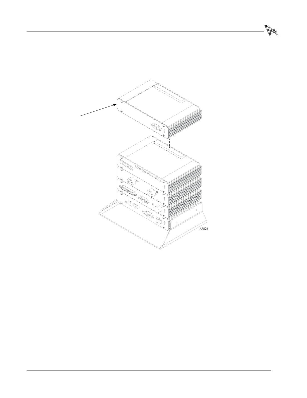
1 Verify the main dyno power is disconnected.
2 Turn off the main power switch on the CPU Module unplug the power cord.
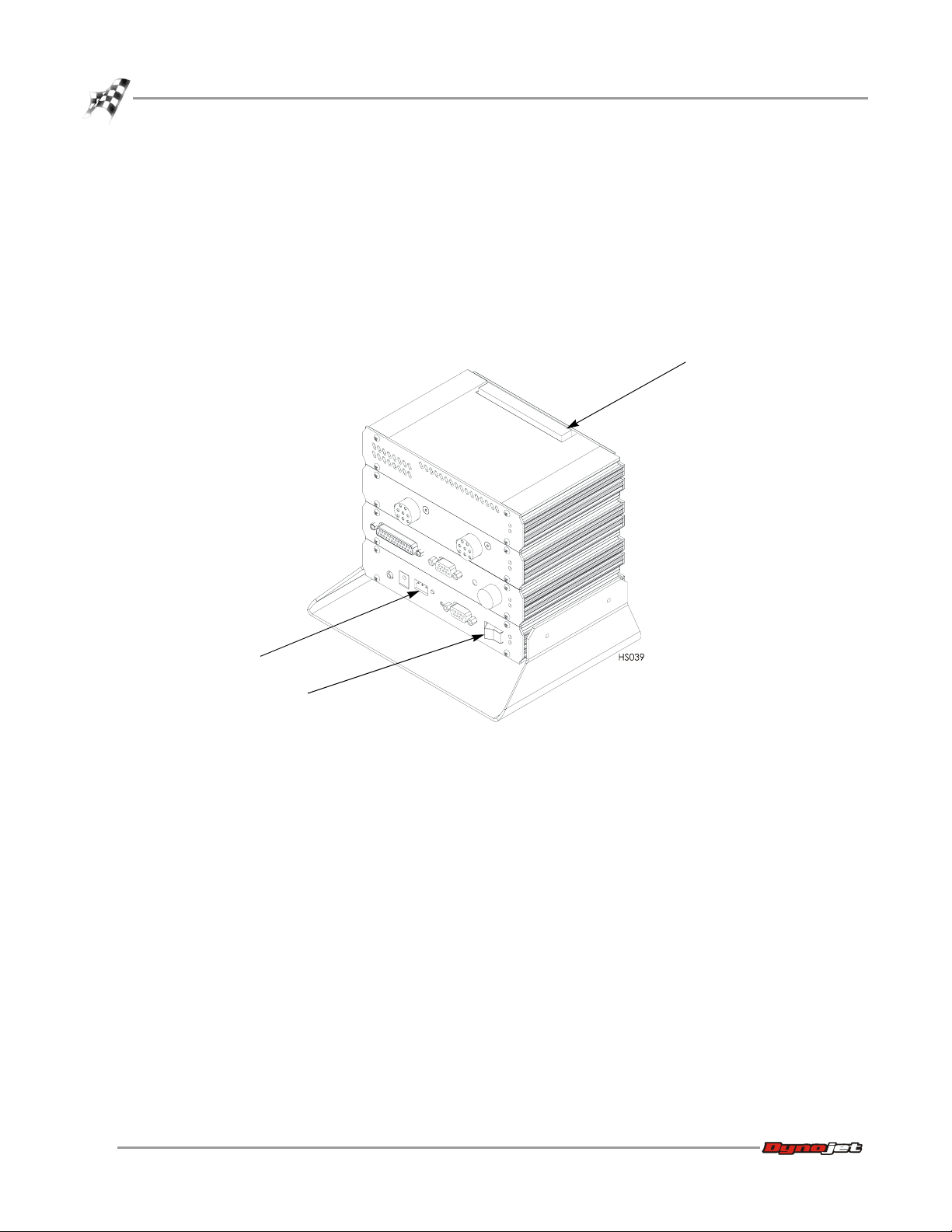
3 Remove the dust cover from the existing top module.
dust cover
power cord input
power switch
Figure 1-1: Remove the Dust Cover
1-4
Compressed Air Air Fuel Ratio Module Installation and User Guide
Page 9
AIR FUEL RATIO MODULE AND COMPRESSED AIR PUMP INSTALLATION
Air Fuel Module Installation
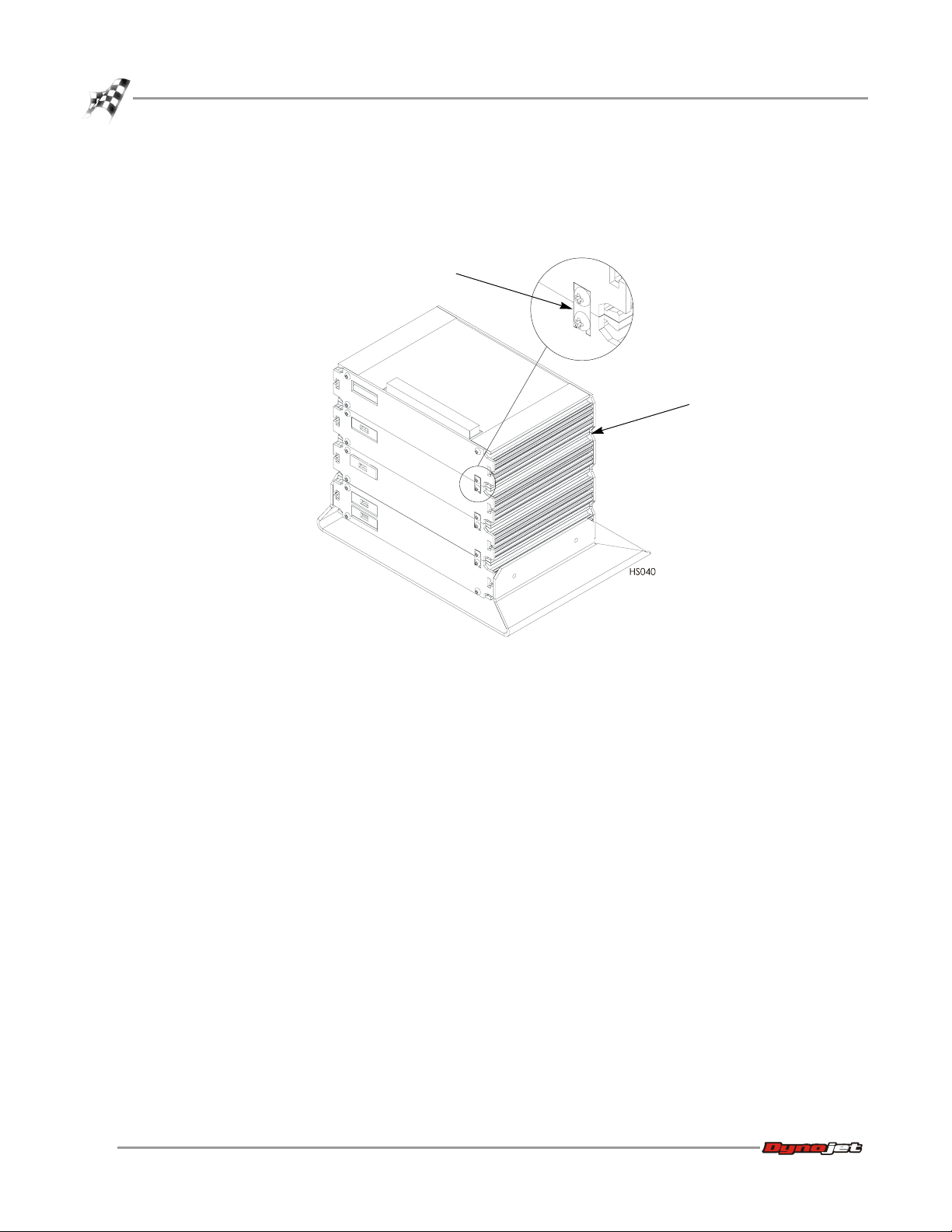
4 Loosen the top right screw on the back of the existing top module.
5 Install the Air Fuel Module into the existing top module. Place the dust cover,
removed in step 3, on the Air Fuel Module.
air fuel module
Figure 1-2: Install the Air Fuel Module
Version 5 Compressed Air Air Fuel Ratio Module Installation and User Guide
1-5
Page 10
CHAPTER 1
Air Fuel Module Installation
6 Secure the grounding strap on the back of the Air Fuel Module to the existing top
module.
7 Secure the Air Fuel Module to the dyno electronics with the plastic tie straps (one
on each side).
grounding strap
plastic tie strap
Figure 1-3: Secure the Grounding Strap
1-6
Compressed Air Air Fuel Ratio Module Installation and User Guide
Page 11
AIR FUEL RATIO MODULE AND COMPRESSED AIR PUMP INSTALLATION
Air Fuel Module Installation
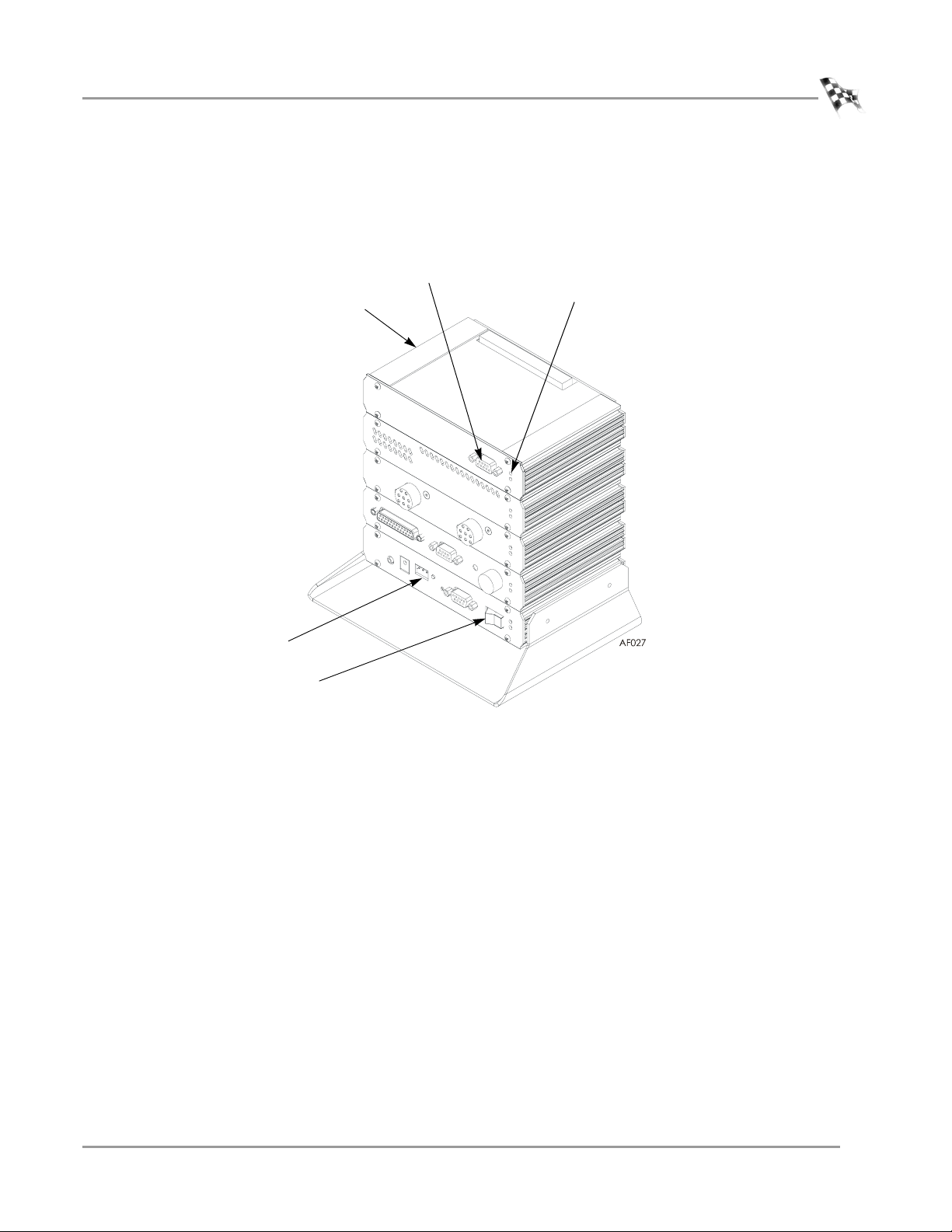
8 Attach the 15-pin connector on the sensor cable to the front of the Air Fuel
Module and tighten down the screws.
9 Attach the power cord to the dyno electronics and turn the power switch on.
The green LED light on the Air Fuel Module should now be on.
sensor cable and port
green LED light
air fuel module
power cord input
power switch
Figure 1-4: Attach the Sensor Cable
Version 5 Compressed Air Air Fuel Ratio Module Installation and User Guide
1-7
Page 12

CHAPTER 1
Compressed Air Pump Assembly
COMPRESSED AIR PUMP ASSEMBLY
. . . . . . . . . . . . . . . . . . . . . . . . . . . . . . . . . . .
This section describes how to set up the compressed air pump assembly. Refer to
Appendix A for on-board dyno installation instructions.
COMPRESSED AIR REQUIREMENTS
The following requirements are needed for the compressed air pump assembly:
• Clean and dry air, 100 psi or greater, 5 CFM or better flow
• 1/4-inch NPT pipe thread connector (to attach air to the solenoid or pump ball
valve)
• optional air regulator
SETTING UP THE STAND ASSEMBLY
Secure the upright to the base using three 1/4-20 x 5/8-inch pan-head torx screws.
upright
screw
base
Figure 1-5: Stand Assembly
1-8
Compressed Air Air Fuel Ratio Module Installation and User Guide
Page 13

AIR FUEL RATIO MODULE AND COMPRESSED AIR PUMP INSTALLATION
INSTALLING THE PUMP ASSEMBLY ON THE STAND
Use the following instructions to install the pump assembly on the stand. Refer to
Appendix A for on-board dyno installation instructions.
1 Open the toggle clamp and slide the pump assembly on the upright.
2 Close the toggle clamp to secure the pump in place.
3 Secure the sensor(s) to the pump assembly.
Note: Make sure the sensor is on top.
4 Attach the compressed air line to the solenoid.
Note: The compressed air must be clean and dry, 100 psi or greater.
5 Attach the silicone tube(s) to the sensor block.
Note: The length of the silicone tube can be adjusted for your application.
6 Attach the copper sample tube(s) to the silicone tube(s).
Compressed Air Pump Assembly
upright
sensor
attach compressed air
toggle clamp
copper sample tube
silicone tube
attach power cable
Figure 1-6: Installing the Pump Assembly on the Stand
Version 5 Compressed Air Air Fuel Ratio Module Installation and User Guide
1-9
Page 14

CHAPTER 1
Compressed Air Pump Assembly
CONNECTING THE SOLENOID POWER—I SERIES DYNOS
Attach the power cable (P/N 71950403) from PII in the CPI to the solenoid on the
compressed air pump assembly.
CONNECTING THE SOLENOID POWER—NON I SERIES DYNOS
Use the Stand Alone Breakout Board Controlled Compressed Air Pump Remote Kit
(P/N 76493010) to control the air pump assembly using the dyno brakes. When the
dyno brakes are released, the compressed air pump will activate; when the dyno
brake are applied, the compressed air pump will deactivate.
Note: In order for the AFR pump to operate as expected, the jumper settings
must be set to digital brake or eddy current brake and digital brake. Refer to
Figure 1-7 on page 1-11. If these jumper settings are not appropriate for your
dyno application, you must use the manual ball valve (P/N 24300000).
If you use the Dynojet model 248 chassis dyno with Proportional air brake,
unfortunately the kit (P/N 76493010) will not work with the required jumpers
settings so you must use the manual ball valve (P/N 24300000).
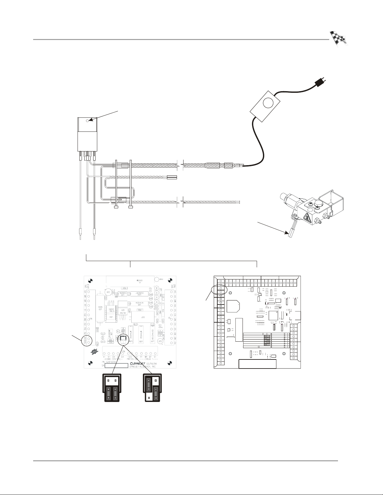
1 Using an existing screw on the Breakout board/Advanced Breakout board, secure
the relay to the board.
2 Remove the brake wires from the Breakout board/Advanced Breakout board.
3 Attach the two butt connectors on the relay cable (P/N 76950186) to the brake
solenoid wires. Refer to Figure 1-7 on page 1-11.
4 Attach the two wires on the relay cable (P/N 76950186) to the solenoid wire
butt connectors on the compressed air pump assembly. Refer to Figure 1-7 on
page 1-11.
5 Attach the two ferrules on the relay cable (P/N 76950186) to the BRAKE terminal
on the Breakout board/Advanced Breakout board.
6 Verify your jumper settings. Refer to Figure 1-7 on page 1-11.
7 Plug the power supply into a 110/220V outlet.
1-10
Compressed Air Air Fuel Ratio Module Installation and User Guide
Page 15
AIR FUEL RATIO MODULE AND COMPRESSED AIR PUMP INSTALLATION
A
Compressed Air Pump Assembly
secure the relay to one of the
screws on the Breakout
board/Advanced Breakout board
connect to the dyno
brake solenoid wires
connect to the
compressed air
pump assembly
solenoid wires
connect to the BRAKE terminals on the
Breakout board/Advanced Breakout board
Breakout board
brake
J2 J1
eddy current brake
and digital brake
dvanced Breakout board
BRA
brake
c
AP117
J1J2
digital brake
only
Figure 1-7: Routing Cables and Wiring the Breakout Board
Version 5 Compressed Air Air Fuel Ratio Module Installation and User Guide
1-11
Page 16

CHAPTER 1
Compressed Air Pump Assembly
ADJUSTING THE AIR FLOW
To ensure accurate readings, adjust the air flow as necessary to maintain 35L/min. If
you are unable to adjust the air flow to 35L/min., clean the pump then try to adjust
the air flow again. Refer to “Pump Maintenance—Stand Alone” on page 2-8 for more
information.
Adjust the air flow at the end of each exhaust probe to 35 L/min.
1 Attach six inches of the silicon tubing from the top port on the flow meter to the
copper sample tube.
2 Loosen the lock nut.
3 Turn the ball valve to the open position or turn on the air pump using the control
panel.
4 Rotate the vacuum generator exhaust port until the flow meter reads
35 L/min.
5 Tighten the lock nut.
Note: Make sure not to rotate the vacuum generator exhaust port when
tightening the lock nut.
6 Remove air flow meter and the six inches of silicon tube.
Note: Periodically check the air flow and adjust as necessary to maintain 35 L/min.
vacuum generator
exhaust port
sensor
copper sample
tube
lock nut
silicon tube
flow meter
Figure 1-8: Adjusting the Air Flow—Stand Alone
1-12
Compressed Air Air Fuel Ratio Module Installation and User Guide
Page 17

U
SING THE
AIR F
UEL
R
ATIO
C HAPTER
2
M
ODULE
This chapter will walk you through the set up procedures, sampling and viewing air
fuel ratios, and how to maintain and troubleshoot your pump assembly. To ensure
safety and accuracy in the procedures, perform the procedures as they are described.
This chapter is divided into the following categories:
•Module and Pump Set Up, page 2-2
• Sample and View Air Fuel Ratios, page 2-3
• Air Pump Maintenance and Troubleshooting, page 2-7
Compressed Air Air Fuel Ratio Module Installation and User Guide
2-1
Page 18
CHAPTER 2
Module and Pump Set Up
MODULE AND PUMP SET UP
. . . . . . . . . . . . . . . . . . . . . . . . . . . . . . . . . . .
This section describes the set up procedures for the Air Fuel Ratio Module and
compressed air pump assembly.
1 Run the vehicle and allow the vehicle to warm up. Excess condensed water is
produced during warm up which can damage the air pump assembly. Allowing
the vehicle to warm up removes this excess water.
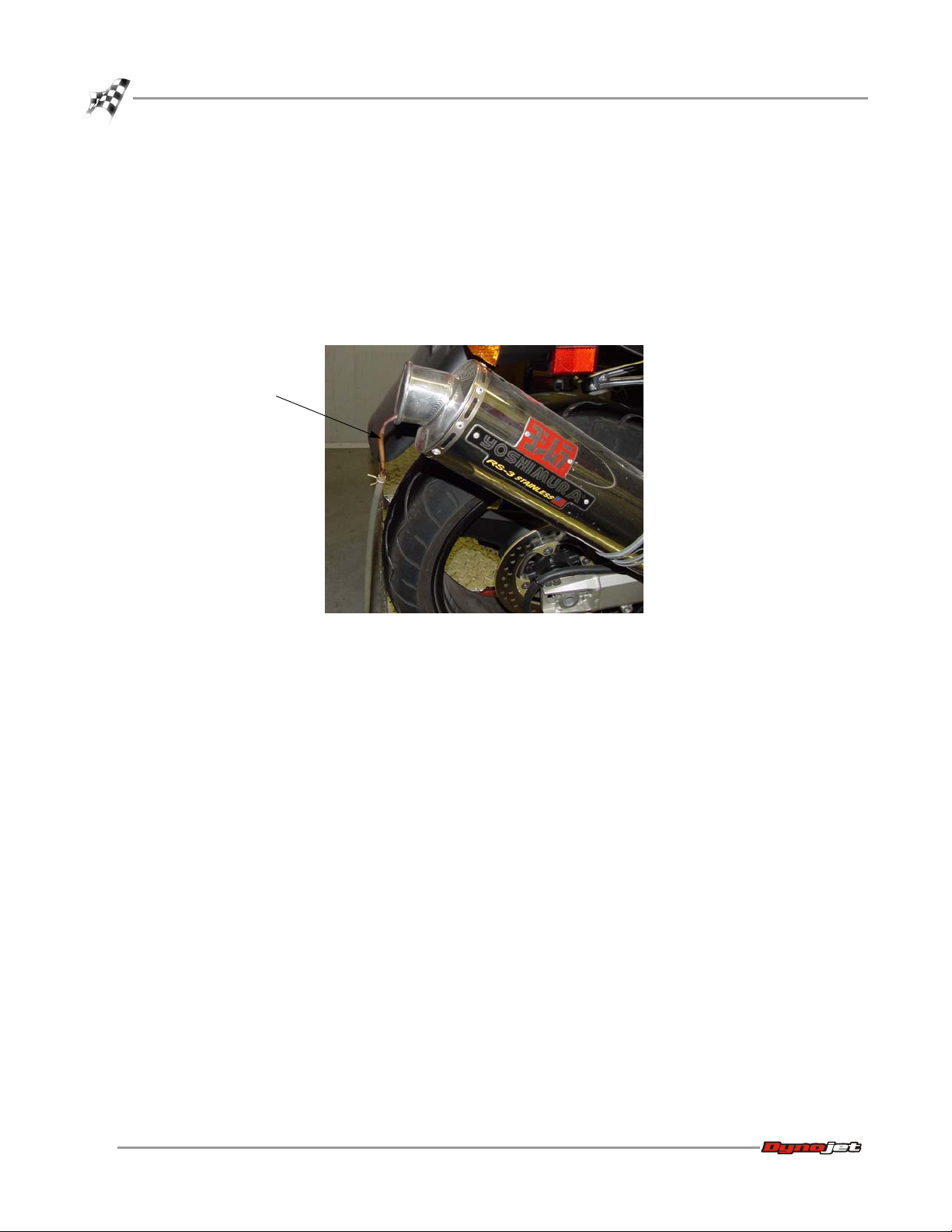
2 Place the copper sample tube(s) in the exhaust pipe(s) of the test vehicle.
copper sample
tube
Figure 2-1: Sample Tube Placement
3 Turn on the dyno electronics power. Verify the Air Fuel Ratio Module power
light is on.
4 Turn on the compressed air to the pump assembly.
2-2
Compressed Air Air Fuel Ratio Module Installation and User Guide
Page 19

USING THE AIR FUEL RATIO MODULE
Sample and View Air Fuel Ratios
SAMPLE AND VIEW AIR FUEL RATIOS
. . . . . . . . . . . . . . . . . . . . . . . . . . . . . . . . . . .
This section describes the procedures to sample and view air fuel ratios using
WinPEP 7.
Note: Allow the sensor to preheat before making a run. An orange LED light on
the Air Fuel Ratio Module will light up continuously and the Air/Fuel gauge on the
MakeRun screen will read 18 when the sensor is ready to make a run.
SAMPLING AIR FUEL RATIOS
1 Verify you are in the MakeRun screen.
2Click the MakeRun Configuration button .
3 In the MakeRun Configuration dialog box, verify the Air/Fuel Heater is on and
click OK.
The Air/Fuel Heater will be on by default when the Air Fuel Ratio Module is added
to the dyno electronics.
Note: To ensure repeatable and accurate measurements, the Air/Fuel Heater must
be allowed to heat up to temperature. An orange LED light on the Air Fuel Ratio
Module will light up continuously when the sensor is ready to make a run.
4 Select the Air/Fuel Type from the drop down list.
Figure 2-2: MakeRun Configuration Window—Air/Fuel Heater
air/fuel heater
must be on
select air/fuel type
Version 5 Compressed Air Air Fuel Ratio Module Installation and User Guide
2-3
Page 20

CHAPTER 2
Sample and View Air Fuel Ratios
5 Verify the air pump assembly is on.
6 Press the green sample button on the pendent to begin recording data.
Note: For more information on how to make a run, refer to the WinPEP 7 User
Guide (on your WinPEP CD or at www.dynojet.com) or the WinPEP 7 Online
Help.
7 Press the sample button a second time to stop sampling.
air/fuel gauge
Figure 2-3: MakeRun Screen—Sampling
Be sure to turn the Air Fuel Heater off when not in use for long periods of time.
2-4
Compressed Air Air Fuel Ratio Module Installation and User Guide
Page 21

browse
directories
VIEWING AND GRAPHING AIR/FUEL RUNS
For more information about graph functions and displays, refer to the WinPEP 7 User
Guide (on your WinPEP CD or at www.dynojet.com) or the WinPEP 7 Online Help.
1 Verify you are in the Graph screen.
2Select File
3 Browse the directory and select a run file. You may also select multiple run files.
A preview of the graph will appear. The graph preview is configurable but not
required to open the run file.
4 Once you have found the run and configured the graph preview (optional),
click Open.
!
Open.
USING THE AIR FUEL RATIO MODULE
Sample and View Air Fuel Ratios
run file
graph preview
Figure 2-4: Graph Screen—Open Dialog Box
Version 5 Compressed Air Air Fuel Ratio Module Installation and User Guide
2-5
Page 22

CHAPTER 2
Sample and View Air Fuel Ratios
The run information is displayed in the ListView along with a graph of the run.
5 Click on the axis channel label and choose Air/Fuel from the list.
Note: Available channels may differ depending on your dyno model and
configuration.
The graph will now display the run with air/fuel readings.
axis channel
label
choose air/fuel from
the list of options
Figure 2-5: Main Graph Display with Air/Fuel
2-6
Compressed Air Air Fuel Ratio Module Installation and User Guide
Page 23

USING THE AIR FUEL RATIO MODULE
Air Pump Maintenance and Troubleshooting
AIR PUMP MAINTENANCE AND TROUBLESHOOTING
. . . . . . . . . . . . . . . . . . . . . . . . . . . . . . . . . . .
This section contains sensor information and describes the procedures for
maintaining and troubleshooting the pump assembly.
Make sure you are aware of the following items:
• Keep the air pump upright. Tipping the pump may result in damage to the sensor.
• Leaks in the system will result in erroneous readings. Verify there are no cracks or
holes in the hoses. Verify the sensor is seated properly in the sensor block.
SENSOR INFORMATION
Under optimal conditions, the sensor life can exceed 1500 hours. When using leaded
race fuel, 2.5 grams of lead per gallon of fuel will reduce the expected life of the
sensor to less than 100 hours.
The sensor is not covered by a warranty. Be sure to read and understand the
Compressed Air Air Fuel Ratio Module Installation and User manual.
CORRECTING LEAN AIR FUEL READINGS
Refer to the instructions below if you are experiencing air fuel ratio readings that are
leaner than you expected.
1 Verify the pump is on.
2 Check the system for restrictions in the air flow such as a kinked hose or dirty
pump.
3 Verify the copper sample tube is not kinked or clogged and is inserted into the
exhaust as far as possible. Refer to Figure 2-1.
4 Check for leaks in the system.
4a Verify all hoses are securely attached to the fittings.
4b Verify there are no cracks or holes in the hoses.
4c Verify the sensor is seated properly in the sensor block.
Version 5 Compressed Air Air Fuel Ratio Module Installation and User Guide
2-7
Page 24

CHAPTER 2
Air Pump Maintenance and Troubleshooting
PUMP MAINTENANCE—STAND ALONE
To ensure accurate readings, pump maintenance should be performed every six
months, or sooner, depending on usage. Periodically check the air flow and adjust as
necessary to maintain 35 L/min for each sample tube. If you are unable to adjust the
air flow to 35 L/min, clean the pump. Use a solvent to clean all pump pieces very
carefully.
1 Remove the ball valve or solenoid (for pumps using the control pod).
2 Loosen the lock nut.
3 Remove the vacuum generator exhaust port.
4 Remove the venturi body.
5 Remove the sensor(s) from the sensor block.
6 Remove the two screws securing the sensor block to the toggle clamp.
7 Use a solvent to carefully clean the vacuum generator exhaust port, venturi body,
and sensor block.
Note: Be careful not to damage the internal structure of the venturi body.
8 Install the sensor block using the two screws removed earlier.
9 Install the venturi body, vacuum generator exhaust port, and ball valve or
solenoid.
10 Install the sensor(s).
11 Replace the silicon and copper tubing if necessary.
12 Re-calibrate the pump using the flow meter. Refer to page 1-12 for more
information.
vacuum generator
exhaust port
lock nut
venturi body
toggle clamp
sensor block
solenoid
Figure 2-6: Pump Maintenance—Stand Alone Pump
sensor
copper sample
tube
silicon tube
2-8
Compressed Air Air Fuel Ratio Module Installation and User Guide
Page 25

PUMP MAINTENANCE—ON DYNO
To ensure accurate readings, pump maintenance should be performed every six
months, or sooner, depending on usage. Periodically check the air flow and adjust as
necessary to maintain 35 L/min for each sample tube. If you are unable to adjust the
air flow to 35 L/min, clean the pump. Use a solvent to clean all pump pieces very
carefully.
1 Remove the eight screws securing the drum module panel to the dyno. Set the
screws and the panel aside. For more information on removing the panel, refer to
your dyno installation guide.
2 Remove the hose connecting the sensor block and the venturi body.
3 Remove the two screws securing the sensor block to the pump housing.
USING THE AIR FUEL RATIO MODULE
Air Pump Maintenance and Troubleshooting
pump housing
sensor block screws
sensor block
(not visible from this view)
venturi body
hose
Figure 2-7: Remove the Screws Securing the Sensor Block
Version 5 Compressed Air Air Fuel Ratio Module Installation and User Guide
2-9
Page 26

CHAPTER 2
Air Pump Maintenance and Troubleshooting
4 Remove the sensor(s) from the sensor block.
5 Remove the sensor block.
6 Remove the silicon tube from the sensor block.
7 Loosen the vacuum generator lock nut.
8 Remove the vacuum generator exhaust port and venturi body.
9 Unscrew the venturi body from the solenoid.
10 Use a solvent to carefully clean the vacuum generator exhaust port, venturi body,
and sensor block.
Note: Be careful not to damage the internal structure of the venturi body.
11 Secure the solenoid to the venturi body.
12 Install the vacuum generator exhaust port to the venturi body.
13 Secure the sensor block to the pump housing using the two screws removed
earlier.
14 Install the sensor(s).
15 Replace the silicon tube between the sensor block and the venturi body.
16 Replace the silicon tube to the sensor block.
17 Re-calibrate the pump using the flow meter. Refer to page A-5 for more
information.
sensor
silicon tube
sensor block
Figure 2-8: Pump Maintenance—On Dyno Pump
2-10
Compressed Air Air Fuel Ratio Module Installation and User Guide
vacuum generator
exhaust port
venturi body
solenoid
lock nut
Page 27

A PPENDIX
A
ON-B
This appendix provides instructions for installing the compressed air pump on your
motorcycle dynamometer. To ensure safety and accuracy in the procedures, perform
the procedures as they are described.
OARD
D
YNO INSTALLATION
Compressed Air Air Fuel Ratio Module Installation and User Guide
A-1
Page 28

APPENDIX A
Installation
INSTALLATION
. . . . . . . . . . . . . . . . . . . . . . . . . . . . . . . . . . .
This section describes how to install the compressed air pump assembly on your
motorcycle dynamometer.
COMPRESSED AIR REQUIREMENTS
The following requirements are needed for the on-board compressed air pump
assembly:
• Clean and dry air, 100 psi or greater, 5 CFM or better flow
• Fittings to hook your air system to a 3/8-inch inside diameter hose (if no air brake is
present)
• optional air regulator
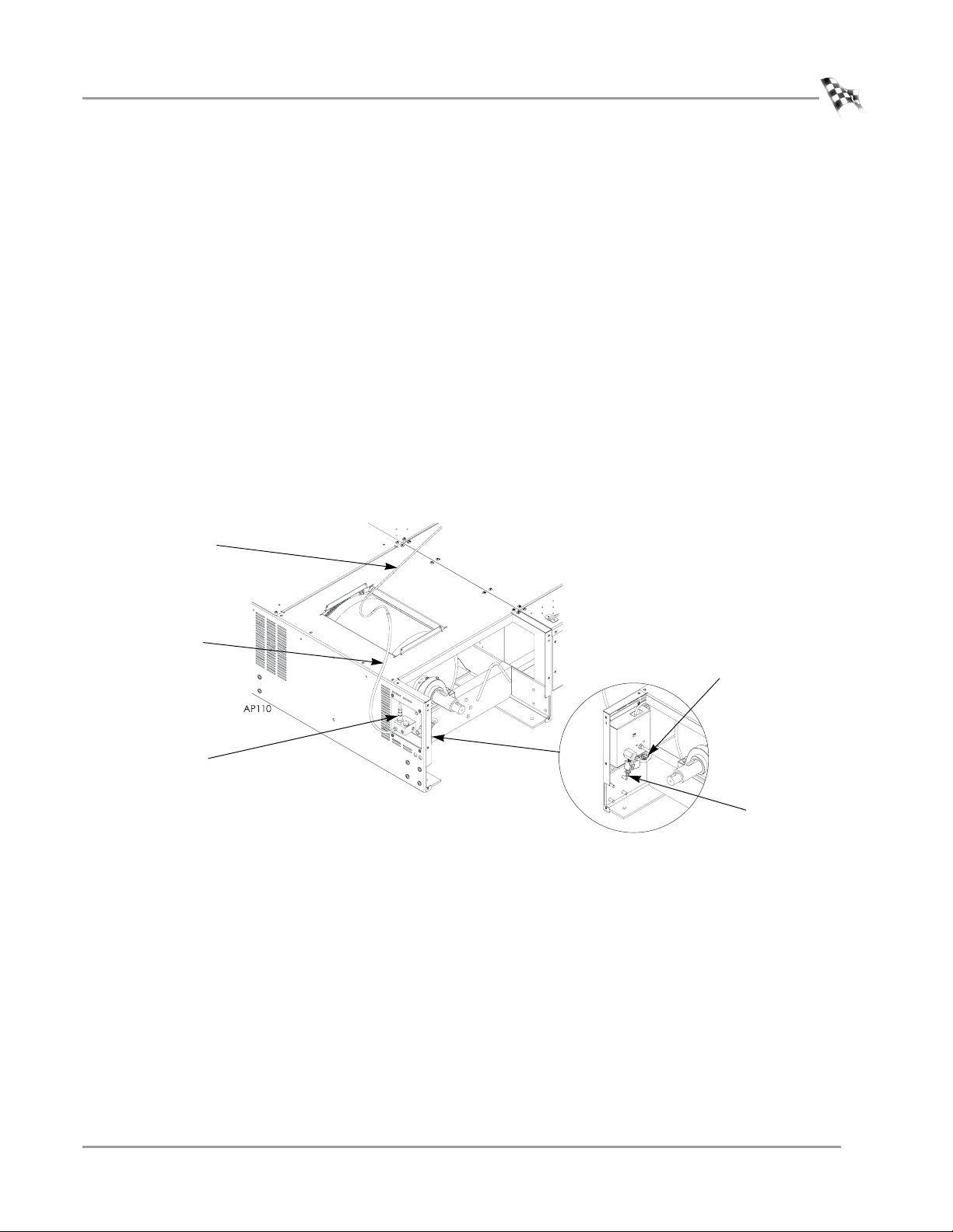
INSTALLING THE PUMP ASSEMBLY ON THE DYNO
1 Remove the eight screws securing the drum module panel to the dyno. Set the
screws and the panel aside. For more information on removing the panel, refer to
your dyno installation guide.
2 Secure the pump housing to the dyno using four 1/4-20 torx screws.
pump housing
Figure A-1: Install the Pump Housing
A-2
Compressed Air Air Fuel Ratio Module Installation and User Guide
Page 29
ON-BOARD DYNO INSTALLATION
Installation
3 Run the provided air hose from the air pump assembly to the front of your dyno.
If you have an air brake, refer to “Installing the Air Hose with the Air Brake” on
page A-4.
You will need to remove the carriage assembly and top center cover to route the
air hose. Refer to your dyno installation guide for instruction on removing the top
cover.
4 Route the air hose through the air access holes in the front of the dyno.
5 Attach the hose to your air supply.
6 Attach the sensor.
7 Attach the silicone hose and copper sample tube to the sensor block.
8 Attach the sensor cable to the corresponding cable from the inside back panel of
the dyno.
9 Attach the connector from the pump solenoid to the cable on the inside back
panel of the dyno.
10 Replace the top center cover and carriage assembly.
11 Replace the drum module panel using the screws removed earlier.
copper sample
tube
silicon tube
sensor
solenoid connector
attach air
Figure A-2: Installing the Sensor and Copper Sample Tube
Version 5 Compressed Air Air Fuel Ratio Module Installation and User Guide
A-3
Page 30
APPENDIX A
Installation
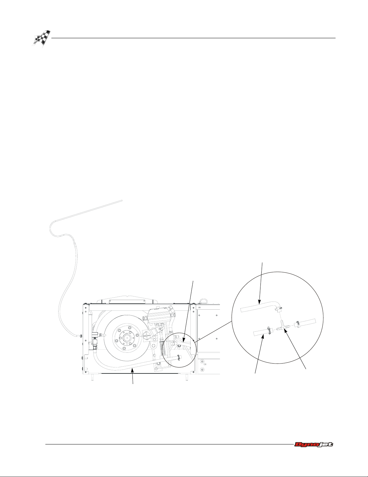
INSTALLING THE AIR HOSE WITH THE AIR BRAKE
Use the following instructions to install the air hose when the air brake is installed.
1 Install the tee.
1a Cut the hose running from the air brake as shown in Figure A-3.
1b Slide a hose clamp over each piece of hose.
1c Insert the tee.
1d Secure the hose clamps.
2 Measure the distance from the tee to the air pump assembly and cut a piece of
hose.
3 Attach the hose to the air pump assembly. This connection does not require a
hose clamp.
4 Slide a hose clamp over the hose.
Note: The hose clamp is only needed on the tee end.
5 Slide the hose over the tee.
6 Secure the hose clamp.
AP115
air hose to the pump
air hose to the brake
air hose to the brake
cut here
tee
air hose to the pump
Figure A-3: Installing the Air Hose with the Air Brake
A-4
Compressed Air Air Fuel Ratio Module Installation and User Guide
Page 31

ADJUSTING THE AIR FLOW
To ensure accurate readings, adjust the air flow as necessary to maintain 35L/min. If
you are unable to adjust the air flow to 35L/min. for each sample tube, clean the
pump then try to adjust the air flow again. Refer to “Pump Maintenance—On Dyno”
on page 2-9 for more information.
Adjust the air flow at the end of the exhaust probe to 35 L/min.
1 Attach six inches of the silicon tubing from the top port on the flow meter to the
copper sample tube.
2 Loosen the lock nut.
3 Turn on the air pump with the control panel.
4 Rotate the vacuum generator exhaust port until the flow meter reads
35 L/min.
5 Tighten the lock nut.
Note: Make sure not to rotate the vacuum generator exhaust port when
tightening the lock nut.
6 Remove the air flow meter and the six inches of silicon tube.
Note: Periodically check the air flow and adjust as necessary to maintain 35 L/min.
copper sample
tube
ON-BOARD DYNO INSTALLATION
Installation
silicon tube
sensor
vacuum generator exhaust port
and lock nut
flow meter
Figure A-4: Adjusting the Air Flow—On Dyno
Version 5 Compressed Air Air Fuel Ratio Module Installation and User Guide
A-5
Page 32

Page 33

 Loading...