

Page 1
Page 2

©2005 Dynojet Research, Inc. All Rights Reserved.
Analog Module Installation and User Guide
This manual is copyrighted by Dynojet Research, Inc., hereafter referred to as Dynojet,
and all rights are reserved. This manual, as well as the software described in it, is
furnished under license and may only be used or copied in accordance with the terms of
such license. This manual is furnished for informational use only, is subject to change
without notice, and should not be construed as a commitment by Dynojet. Dynojet
assumes no responsibility or liability for any error or inaccuracies that may appear in this
manual. Except as permitted by such license, no part of this manual may be reproduced,
stored in a retrieval system, or transmitted, in any form or by any means, electronic,
mechanical, recording, or otherwise, without the prior written permission of Dynojet.
The Dynojet logo is a trademark of Dynojet Research, Inc.
Any trademarks, trade names, service marks, or service names owned or registered by any
other company and used in this guide are the property of their respective companies.
Dynojet Research, Inc., 2191 Mendenhall Drive, North Las Vegas, Nevada 89081, USA.
Printed in USA.
Part Number: 98198118 Version 01 (08/2005)
Page 3

T
ABLE OF
C
ONTENTS
Chapter 1 Analog Module Installation
Introduction . . . . . . . . . . . . . . . . . . . . . . . . . . . . . . . . . . . . . . . . . . . . . . . . . .1-2
Conventions Used In This Manual . . . . . . . . . . . . . . . . . . . . . . . . . . . . . . .1-2
Technical Support . . . . . . . . . . . . . . . . . . . . . . . . . . . . . . . . . . . . . . . . . . .1-2
Parts List . . . . . . . . . . . . . . . . . . . . . . . . . . . . . . . . . . . . . . . . . . . . . . . . . .1-2
Analog Module Installation . . . . . . . . . . . . . . . . . . . . . . . . . . . . . . . . . . . . .1-3
Connecting and Disconnecting Power to the Dyno . . . . . . . . . . . . . . . . . .1-3
Accessing the Dyno Electronics . . . . . . . . . . . . . . . . . . . . . . . . . . . . . . . . .1-3
Installing the Analog Module . . . . . . . . . . . . . . . . . . . . . . . . . . . . . . . . . . .1-5
Routing the Analog Module Cable Assembly . . . . . . . . . . . . . . . . . . . . . . .1-6
Connecting the Sensor Cables . . . . . . . . . . . . . . . . . . . . . . . . . . . . . . . . . .1-7
Chapter 2 Analog Channel Configuration and Viewing Data
Analog Channel Configuration . . . . . . . . . . . . . . . . . . . . . . . . . . . . . . . . . .2-2
Configuring the Analog Channel(s) . . . . . . . . . . . . . . . . . . . . . . . . . . . . . .2-2
Customizing Sensor Tables . . . . . . . . . . . . . . . . . . . . . . . . . . . . . . . . . . . .2-4
Saving and Loading Sensor Tables . . . . . . . . . . . . . . . . . . . . . . . . . . . . . . .2-5
Editing a Gauge . . . . . . . . . . . . . . . . . . . . . . . . . . . . . . . . . . . . . . . . . . . . .2-6
Viewing Data . . . . . . . . . . . . . . . . . . . . . . . . . . . . . . . . . . . . . . . . . . . . . . . . .2-7
Configuring the Graph . . . . . . . . . . . . . . . . . . . . . . . . . . . . . . . . . . . . . . .2-7
Analog Module Installation and User Guide
i
Page 4

Page 5

A
NALOG
M
C HAPTER
1
ODULE INSTALLATION
This document provides instructions for installing and using the Analog Module with
WinPEP 7. To ensure safety and accuracy in the procedures, perform the procedures
as they are described.
This chapter will walk you through installing the Analog Module, routing the Analog
Module cable assembly, and connecting the sensor cables. Chapter two will walk you
through configuring your Analog Module and viewing the data.
Document Part Number: 98198118
Version 0 1
Last Updated: 08-31-05
This chapter is divided into the following categories:
•Introduction, page 1-2
• Analog Module Installation, page 1-3
• Routing the Analog Module Cable Assembly, page 1-6
• Connecting Sensor Cables, page 1-7
Analog Module Installation and User Guide
1-1
Page 6
CHAPTER 1
Introduction
INTRODUCTION
. . . . . . . . . . . . . . . . . . . . . . . . . . . . . . . . . . .
The Analog Module, when added to Dynojet's market leading inertia dynamometer,
results in a complete vehicle performance test.
The Analog Module is capable of measuring any 0-5 volt signal on a vehicle and comes
with an unterminated cable to allow you to hook up your own sensors. Additional
sensors and cables are available from Dynojet.
CONVENTIONS USED IN THIS MANUAL
The conventions used in this manual are designed to protect both the user and the
equipment.
example of convention description
The Caution icon indicates a potential hazard to the
dynamometer equipment. Follow all procedures
exactly as they are described and use care when
performing all procedures.
The Warning icon indicates potential harm to the
person performing a procedure and/or the
dynamometer equipment.
part number description quantity
66104002 Analog Module Sub-Assembly 1
76950818 Cable, 4 Channel Auxiliary Input Module 1
76950416 Cable, Sensor-Unterminated 1
The following sensors are optional:
76199007 0-100 PSI Gage (Relative) Sensor and Cable
76199006 0-50 PSI Absolute Sensor and Cable
Bold
TECHNICAL SUPPORT
For assistance, please contact Dynojet Technical Support at 1-800-992-3525, or write
to Dynojet at 2191 Mendenhall Drive, North Las Vegas, NV 89081.
Visit us on the World Wide Web at www.dynojet.com where Dynojet provides state of
the art technical support, on-line shopping, 3D visualizations, and press releases
about our latest product line.
PARTS LIST
The following table lists all of the parts included in the Analog Module installation kit
(P/N 66104002). Check your kit against the parts listed to make sure you have
received all of the parts. If any part is missing, contact Dynojet Technical Support.
Highlights items you can select on in the software
interface, including buttons and menus.
The arrow indicates a menu choice. For example,
“select File
then select the Open choice on the File menu.”
Open” means “select the File menu,
1-2
Analog Module Installation and User Guide
Page 7
ANALOG MODULE INSTALLATION
ANALOG MODULE INSTALLATION
. . . . . . . . . . . . . . . . . . . . . . . . . . . . . . . . . . .
This section describes how to access the dyno electronics, install the Analog Module,
route the Analog Module cable assembly, and connect the sensor cables.
CONNECTING AND DISCONNECTING POWER TO THE DYNO
Always disconnect the power before beginning any installation procedures.
Refer to your dyno installation manual for more information on disconnecting the
power to your specific dyno.
1 Use the main breaker to turn power on and off to the dyno.
2 Disconnect the power plug to ensure all power has been removed from the dyno.
ACCESSING THE DYNO ELECTRONICS
You will need to access your dyno electronics in order to add the Analog Module. Use
the following steps to access the dyno electronics.
1 Turn off the main power to the dyno.
Analog Module Installation
To prevent possible injury always disconnect all power to the dyno.
2 Locate the dyno electronics enclosure.
Refer to your dyno installation manual for more information on locating and
accessing the dyno electronics encloser.
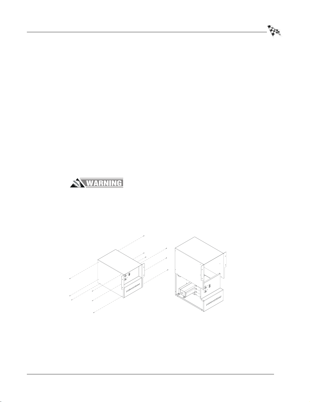
3 Remove the twelve screws securing the cover and lift the cover off.
Figure 1-1: Remove Electronics Enclosure Cover
Vers ion 1 Analog Module Installation and User Guide
1-3
Page 8

CHAPTER 1
Analog Module Installation
4 Add the Analog Module to the top of the dyno electronics. Refer to “Installing the
Analog Module” on page 1-5.
5 Leave the dyno electronics enclosure out. You will need to route any sensor
cables to the Analog Module as they are installed.
dyno electronics
Figure 1-2: Inside the Electronics Enclosure
1-4
Analog Module Installation and User Guide
Page 9

INSTALLING THE ANALOG MODULE
1 Verify the main dyno power is disconnected.
2 Turn off the main power switch on the CPU Module and unplug the power cord.
3 Remove the dust cover from the existing top module.
ANALOG MODULE INSTALLATION
Analog Module Installation
dust cover
power cord
input
power switch
Figure 1-3: Remove Dust Cover
4 Loosen the top right screw on the back of the existing top module.
5 Plug the Analog Module into the existing top module. Place the dust cover,
removed in step 3, on the Analog Module.
6 Secure the grounding strap on the back of the Analog Module to the existing top
module.
7 Secure the Analog Module to the dyno electronics with the plastic tie straps (one
on each side).
grounding strap
Figure 1-4: Secure Grounding Strap
plastic tie strap
Vers ion 1 Analog Module Installation and User Guide
1-5
Page 10

CHAPTER 1
Analog Module Installation
ROUTING THE ANALOG MODULE CABLE ASSEMBLY
1 Route the Analog Module cable assembly through the cable clamp on the back of
the dyno electronics enclosure.
1a Loosen the two screws and lift the clamp up to slide the analog cable
through.
1b Secure the clamp with the two screws.
2 Attach the connector on the Analog Module cable assembly to the front of the
Analog Module.
cable clamp
analog module
cable assembly
analog module
Figure 1-5: Attach the Analog Module Cable Assembly to the Analog Module
1-6
Analog Module Installation and User Guide
Page 11

CONNECTING THE SENSOR CABLES
1 Attach the sensor cable(s) to the Analog Module cable assembly. The two types of
sensor cables are described below and shown in Figure 1-6.
• An unterminated sensor cable, included with your Analog Module, is designed
to connect directly to or “tap into” the vehicle’s existing sensors. Wire the
cable as follows:
•Red is 5 VDC
• Green is sensor output
•Black is GND
• A terminated sensor cable is designed with a specific sensor attached for
measuring a specific pressure.
2 Once the sensor cable is connected to the analog cable, you will need to route the
sensor cable to the appropriate location on your vehicle for the pressure you are
measuring.
connect to
analog module
analog module cable assembly
ANALOG MODULE INSTALLATION
Analog Module Installation
terminated sensor cable
unterminated sensor cable
red
green
black
Figure 1-6: Attach the Sensor Cable(s) to the Analog Module Cable Assembly
3 Attach the power cord to the CPU Module and turn the dyno electronics power
switch on.
4 Connect all power to the dyno.
5 The green LED light on the Analog Module should now be on.
6 Replace the dyno electronics cover. Refer to Figure 1-1 on page 1-3.
Vers ion 1 Analog Module Installation and User Guide
1-7
Page 12

Page 13

A
NALOG
C
HANNEL
C HAPTER
C
ONFIGURATION
2
AND
This chapter provides instructions for configuring the Analog Module and viewing the
data with WinPEP 7. To ensure safety and accuracy in the procedures, perform the
procedures as they are described.
This chapter is divided into the following categories:
• Analog Channel Configuration, page 2-2
•Viewing Data, page 2-7
V
IEWING
D
ATA
Analog Module Installation and User Guide
2-1
Page 14

CHAPTER 2
Analog Channel Configuration
ANALOG CHANNEL CONFIGURATION
. . . . . . . . . . . . . . . . . . . . . . . . . . . . . . . . . . .
You can configure up to four different analog channels. Use the following instructions
to configure the analog channel(s).
CONFIGURING THE ANALOG CHANNEL(S)
1 Verify you are in the MakeRun screen.
2 Verify you are connected to the dyno electronics.
Note: You must be connected to the dyno electronics and the Analog Module
must be installed for the analog channels to be available.
Note: For more information on connecting to the dyno electronics, refer to the
WinPEP 7 User Guide (on your WinPEP CD or at
www.dynojet.com/manuals.shtml) or the WinPEP 7 Online Help.
3Select Too ls
4 Select the desired analog channel tab.
5Click the Enable logging on this channel check box.
6Click Sensor Helper.
MakeRun Options Analog Configuration.
analog channel tabs
check box
sensor helper
Figure 2-1: Analog Configuration Window—Select Desired Channel
2-2
Analog Module Installation and User Guide
Page 15

ANALOG CHANNEL CONFIGURATION AND VIEWING DATA
7 Choose a sensor from the drop down list.
8Click OK.
Figure 2-2: Analog Sensor Helper Window—Choose a Sensor
Analog Channel Configuration
sensor drop
down list
9 Enter the analog channel name in the Display Name field.
10 Click OK to enter these changes or click Cancel to abort the changes and return
to the MakeRun screen.
display name
field
Figure 2-3: Analog Configuration Window—Enter the Display Name
Vers ion 1 Analog Module Installation and User Guide
2-3
Page 16

CHAPTER 2
Analog Channel Configuration
CUSTOMIZING SENSOR TABLES
Some sensors may require additional rows. You may customize your sensor table by
adding or removing rows.
1 Right click on the table.
2 Choose Add Row or Remove Row to customize your table.
add row
Figure 2-4: Analog Configuration Window—Customize the Sensor Table
2-4
Analog Module Installation and User Guide
Page 17

ANALOG CHANNEL CONFIGURATION AND VIEWING DATA
SAVING AND LOADING SENSOR TABLES
Commonly used sensor tables may be saved to a file allowing you to load and use
them later.
1Click Save Sensor Table to save the sensor table to a file.
2 Choose a location and click Save.
3Click Load Sensor Table to load a saved sensor table.
4Click OK to load the sensor table or click Cancel to abort the changes and return
to the MakeRun screen.
load sensor
table
Analog Channel Configuration
save sensor
table
Figure 2-5: Analog Configuration Window—Save and Load Sensor Tables
Vers ion 1 Analog Module Installation and User Guide
2-5
Page 18

CHAPTER 2
Analog Channel Configuration
EDITING A GAUGE
You will need to either create a new gauge or edit an existing gauge to represent your
analog channel. For this example, we will edit an existing gauge.
For more detailed information on creating a gauge, refer to the WinPEP 7 manual.
1 Verify you are in Advanced Mode. To change the user level click
To ol s
2 If you are not already there, go to the MakeRun screen. Click the Make Run
button . The last template used is automatically loaded.
3Click the Edit Mode button . You cannot edit gauges unless you are in Edit
Mode.
4 Right click on the gauge and choose Gauge Properties.
5 The Gauge Property Editor dialog box will appear.
Each type of gauge has a slightly different dialog box, but most share the same
properties.
6 Select the analog channel you created earlier from the Data Channel drop down
list.
The analog channel selected automatically appears in the Upper Title and on the
gauge.
Note: You must be connected to the dyno electronics and the Analog Module
must be installed for the list of analog channels to be available.
7Click OK to enter these changes or click Cancel to abort the changes and return
to the MakeRun screen.
Environment Options and click on the General tab.
upper title
2-6
Analog Module Installation and User Guide
data channel
drop down list
Figure 2-6: Gauge Property Editor Dialog Box
Page 19

ANALOG CHANNEL CONFIGURATION AND VIEWING DATA
VIEWING DATA
. . . . . . . . . . . . . . . . . . . . . . . . . . . . . . . . . . .
Once the analog channel is configured, the information will automatically be
recorded when you make a run.
1 Make your dyno run. Refer to the dyno installation and WinPEP 7 manuals for
more detailed information on making a run.
2 By default, a graph of your run will appear. In order to view the analog channel
data recorded, you will need to configure your graph to show the analog channel.
Viewing Data
CONFIGURING THE GRAPH
Once the run is graphed, you can configure the graph to show the analog channel(s)
using the axis selection buttons.
For more detailed information on configuring graphs, refer to your WinPEP 7 user
guide.
1 Click on any of the three axis channel labels.
Note: Available channels may differ depending on your dyno model and
configuration.
2 Choose the analog channel from the list.
axis channel
label
axis channel
options-analog
channels
Figure 2-7: Configuring the Graph Screen
Vers ion 1 Analog Module Installation and User Guide
2-7
Page 20

Page 21

 Loading...