

Page 1

Distributed by Xiamen Overseas Chinese Electronic Co.,LTD (XOCECO)
SERVICE MANUAL
Product Type: LCD TV
Chassis: KS Chassis
Manual Series:
Manual Part#: 9226KS7010
Model Line:
Product Year:
Product Safety Servicing Guidelines....................................................................................1
Remote Control Unit.............................................................................................................2
Main Unit (Front View/Side View/Rear View)........................................................................3
Specifications......................................................................................................................4
Alignment Instructions..........................................................................................................5
Software Upgrade Instructions...........................................................................................11
Working principle analysis of the unit................................................................................15
Block Diagram....................................................................................................................16
Troubleshooting Guides.....................................................................................................17
Wiring Diagram..................................................................................................................22
Schematic Diagram............................................................................................................23
Printed Circuit board layouts..............................................................................................28
Exploded View Parts List....................................................................................................30
CONTENTS
Page 2
Product Safety Servicing Guidelines
Temperature
Scope for operation
0 ~ +50 oC
Scope for storage -20 ~ +60 oC
Humidity Scope for operation 20% ~ 85%
Scope for storage 10% ~ 90%
ATTENTION: This service manual is only for service personnel to take
reference with. Before servicing please read the
following points carefully.
CAUTION: Do not attempt to modify this product in any way.
Ne v er pe r form cu sto m ize d insta l lat i ons wi thou t
manufacturer’s approval.
Unauthorized modifications will not only void the warranty,
but may lead to property damage or user injury.
Service work should be performed only after you are thoroughly
familiar with these safety checks and servicing guidelines.
GRAPHIC SYMBOLS
The exclamation point within an equilateral triangle
is intended to alert the service personnel to
important safety information in the service literature.
The lightning flash with arrowhead symbol within an
equilateral triangle is intended to alert the service
person ne l to the pre sence of noni ns ulated
“dangerous voltage” that may be of sufficient
magnitude to constitute a risk of electric shock.
6. Should there be smoke, abnormal smell or sound from the module,
please shut the power off at once. Likewise, if the screen is not
working after the power is on or in the course of operation, the
power must be cut off immediately and no more operation is allowed
under the same condition.
7. Do not pull out or plug in the connection wire when the module is in
operation or just after the power is off because in this case relatively
high voltage still remains in the capacitor of the driving circuit.
Please wait at least one minute before the pulling out or plugging in
the connection wire.
8. When operating or installing LCD please don't subject the LCD
components to bending, twisting or extrusion, collision lest mishap
should result.
9. As most of the circuitry in LCD TV set is composed of CMOS
integrated circuits, it's necessary to pay attention to anti statics.
Before servicing LCD TV make sure to take anti static measure and
ensure full grounding for all the parts that have to be grounded.
10.There are lots of connection wires between parts behind the LCD
screen. When servicing or moving the set please take care not to
touch or scratch them. Once they are damaged the screen would be
unable to work and no way to get it repaired.
If the connection wires, connections or components fixed by the
thermotropic glue need to disengage when service, please soak the
thermotropic glue into the alcohol and then pull them out in case of
damage.
11.Special care must be taken in transporting or handling it. Exquisite
shock vibration may lead to breakage of screen glass or damage to
driving circuit. Therefore it must be packed in a strong case before
the transportation or handling.
12.For the storage make sure to put it in a place where the environment
can be controlled so as to prevent the temperature and humidity
from exceeding the limits as specified in the manual. For prolonged
storage, it is necessary to house it in an anti-moisture bag and put
them altogether in one place. The ambient conditions are tabulated
as follows:
INSTRUCTIONS
Be sure to switch off the power supply before replacing or welding any
components or inserting/plugging in connection wire. Anti static
measures must be taken (throughout the entire production process!):
a) Do not touch here and there by hand at will;
b) Be sure to use anti static electric iron;
c) It's necessary for the welder to wear anti static gloves.
Please refer to the part list before replacing components that have
special safety requirements. Do not replace with different components
with different specs and type at will.
13. Display of a fixed p ict ure for a lo ng t ime may result in
app e a r a n ce o f p i c t u r e r e s i due o n t h e sc r e e n , a s
commonly c all ed “g hos t shadow”. Th e ext ent of the
residual picture v ari es wi th th e maker of LCD screen.
LCD SERVICING PRECAUTIONS
1. Screens are different from one model to another and therefore not
interchangeable. Be sure to use the screen of the original model for
replacement.
2. The operation voltage of LCD screen is 700-825V. Be sure to take
proper measures in protecting yourself and the machine when
testing the system in the course of normal operation or right after
the power is switched off. Please do not touch the circuit or the
metal part of the module that is in operation mode. Relevant
operation is possible only one minute after the power is switched off.
3. Do not use any adapter that is not identical with the TV set.
Otherwise it will cause fire or damage to the set.
4. Never operate the set or do any installation work in bad environment
such as wet bathroom, laundry, kitchen, or nearby fire source,
heating equipment and devices or exposure to sunlight etc.
Otherwise bad effect will result.
5. If any foreign substance such as water, liquid, metal slices or other
matters happens to fall into the module, be sure to cut the power off
immediately and do not move anything on the module lest it should
cause fire or electric shock due to contact with the high voltage or
short circuit.
This phenomenon doesn't represent failure. This “ghost
shadow” may rema in in the picture for a per iod of time
(several minutes). But wh en ope rat ing it please avoid
displaying still picture in high brightness for a long time.
Points for attention during installation
1. The fr ont pane l of LCD sc ree n is of glass. W hen
installing it please make sure to put it in place.
2. For service or ins tal lat ion it' s ne ces sar y to use
specified screw lest it should damage the screen.
3. Be sure to take anti dust measures. Any foreign
substance that hap pen s to fa ll do wn between the screen
and the glass will affec t the r ece ivi ng an d vie win g effect
4. W hen di sma ntl ing or mounting t he protective par tit ion
plate t hat is u sed for ant i vibration an d insulation p lea se
take ca re to kee p it in intactness so as to avoid hi dde n
trouble.
5. Be su re to protect the c abi net from dam age o r scratch
during service, dismantling or mounting.
1
Page 3
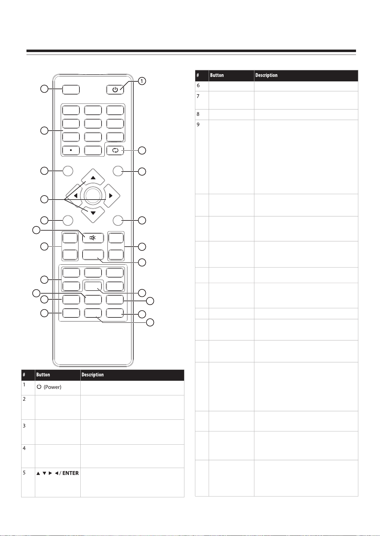
Remote control
Remote Control Unit
10
INPUT POWER
2
1
4
2
5
3
6
3
7
8
0
9
RECALL
13
MENU
MUTE
VOL+/VOL–
VIDEO/HDMI/TV
COMP/VGA
Press to open the on-screen menu.
Press to turn off the sound. Press again to
turn on the sound.
Press to increase or decrease the volume.
Press to select the input source.
• Press VIDEO once to select AV1, twice to
select AV2, three times to select S-Video1,
and four times to select S-Video2.
• Press HDMI once to select HDMI1, twice
to select HDMI2, and three times to select
INFO
4
GUIDE
14
HDMI3.
! Press TV to select TV.
! Press COMP once to select Component1
or twice to select Component2.
! Press VGA to select VGA.
5
MENU
6
7
VOL+
8
VOL- CH
ENTER
MUTE
FAVOR IT E
EXIT
CH
15
<
16
<
10
11
12
SLEEP
ZOOM
PICTURE
Press to set the sleep timer.
Press to select the aspect ratio.
Press to select the picture mode.
17
11
VIDEO
9
COMP
ZOO M
HDMI
MTS/SAP
SLEEP
TV
VGA
CH-LIST
18
19
13
14
RECALL
GUIDE
Press to go to the last viewed channel.
Press to open the DTV program guide (if
available).
12
PICTURE
INPUT
Numbers/Dot(.)
INFO
AUDIO
CCD
20
21
Press to turn on your TV. Press again to put
your TV in Standby mode.
Press to open the INPUT SOURCE menu,
then press 5 or 6 to select the video input
source.
Press to enter channel numbers or the
parental control password. Press the dot
button to select a digital sub-channel.
Press to display the information banner.
Press direction buttons to navigate in the onscreen menus. Press ENTER to confirm
selections in an on-screen menu or to open a
submenu.
15
16
17
18
19
20
21
EXIT
<
CH /CH
FAVORITE
MTS/SAP
CH-LIST
CCD
AUDIO
<
Press to close the on-screen menu.
Press to go to the next or previous channel in
the channel list.
Press to display the favorite channel list.
Press to select the audio mode. For analog
channels, you can select STEREO, SAP
(secondary audio program), or MONO. For
digital channels, you can select the audio
track (if more than one track is available).
Press to open the channel list.
Press to turn closed captioning on or off.
Press to select the sound mode.
2
Page 4
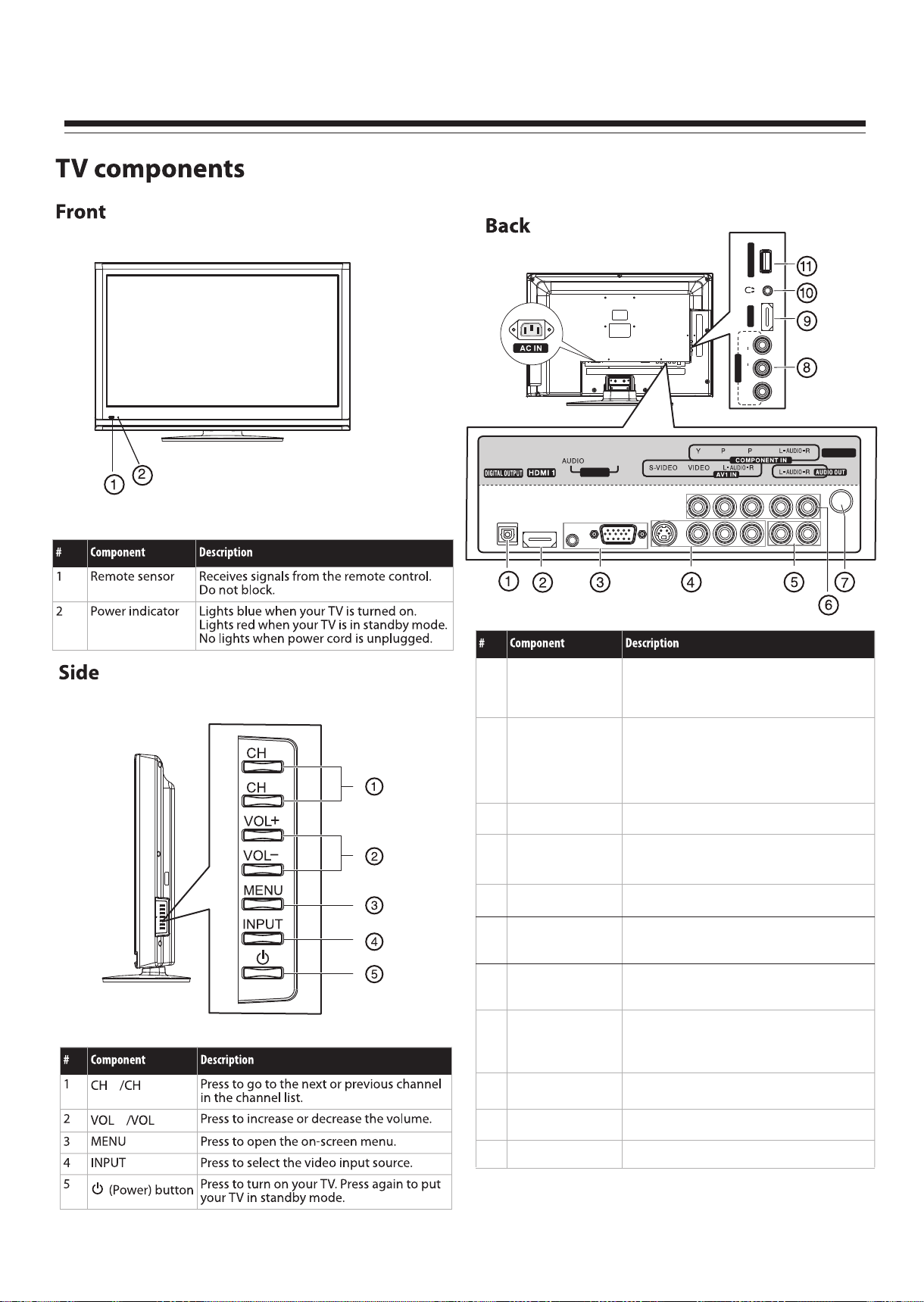
Main Unit (Front View/Side View/Rear View)
SERVI CE PORT
HDMI 2
R
AUDIO
L
AV2 IN
VIDEO
<
<
DIGITAL OUTPUT
1
jack
2
HDMI1 jack
PC IN VGA/AUDIO jacks
3
4
S-VIDEO/AV1 IN
jack
B R
PC IN
VGA
Connect this jack to a digital sound system to
play your TV’s audio through the sound system.
For more information, see “Connecting a digital
sound system” on page 10.
Connect an HDMI device, such as a cable box or
DVD player, to the jack. An HDMI cable carries
both video and audio, so you do not need to
mak e an audio connection. For more
information, see “Connecting an HDMI device”
on page 9.
Connect a computer to these jacks. For more
information, see “Connecting a computer” on page 10.
Connect an AV or S-Video device to these jacks,
then connect audio cables to the audio jacks.
ANT/ CA BLE IN
<
5
AUDIO OUT jack
6
COMPONENT IN
jacks
7
ANT/CABLE IN
jack
8
AV2 IN jack
<
-
+
9
HDMI2 jack
10
Headphone jack
11
SERVICE PORT
Connect an audio amplifier to these jacks.
Connect a component video device to these jacks.
For more information, see “ Connecting a
component video device” on page 9.
Connect an antenna, cable TV, or a satellite box to
this jack. For more information, see “Connecting an
antenna, cable TV, or satellite TV box” on page 8.
Connect an AV device (video and audio) to these
jacks. Match the color of the connectors to the
color of the jacks (yellow for video, red for audio
right, and white for audio left).
Connect an HDMI device, such as a cable box or
DVD player, to this jack.
Plug headphones into this jack.
For software update only. Do not use.
3
Page 5
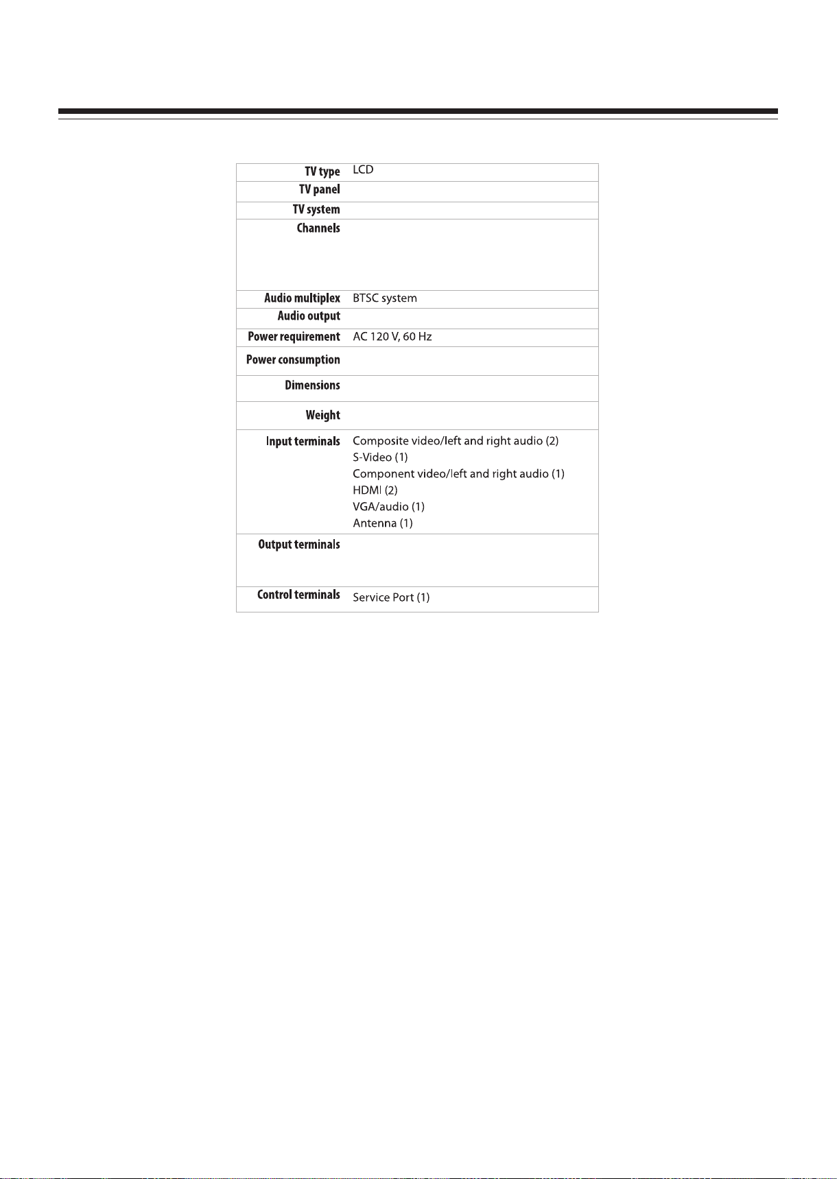
SPECIFICATIONS
26” TF T LCD
NTSC-M, ATSC
VHF: 2-13
UHF: 14-69
CATV: 1-125
CADTV: 1-135
DTV: 2-69
5 W x 2
85 W
646 x 462 x 256 mm (Stand included)
8.2 kg (Stand included)
Audi o left an d right ( 1)
Digi tal out put (1)
Head phone j ack (1)
Note:
1. Design and specifications are subject to change without notice.
2. Weight and dimensions shown are approximate.
3. Specifications and external appearance may be changed for the sake of improvement.
4
Page 6
ALIGNMENT INSTRUCTIONS
1. Test equipment
VG848 (YPbPr, VGA signal generator)
VG849 (HDMI signal generator)
CA210 (color analyzer)
2. Alignment procedure
2.1 Connect all the boards according to wiring diagram. Connect the power supply and
presss “standby” to turn on the TV.
2.1.1 For 32” /37” /42”/46” model
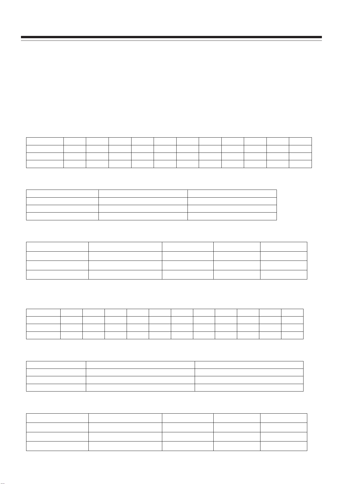
a) In turn measure X508 all pins voltage on Power Board, the value is shown below (Table 1):
Table 1 X508 all pin voltage
Pin 1 2 3 4, 5 6, 7 8 9 10 11 12 13
Min.(V) 4.85 3.25 0 11.3 0 0 4.85 0 4.85 0 2.85
Typical(V) 5.00 3.30 0 12.0 0 0 5.00 0 5.00 0 3.00
Max.(V) 5.35 3.30 0 12.6 0 0 5.35 0 5.35 0 3.15
b) In turn measure X505 all pins voltage on Power Board, the value is shown below (Table 2):
Table 2 X505 all pin voltage
Pin 1, 2 3, 4, 5
Min.(V) 23.8 0
Typical(V) 24.0 0
Max.(V) 25.2 0
c) In turn measure X503 all pins voltage on Power Board, the value is shown below (Table 3):
Table 3 X503 all pin voltage
Pin 1~5 6~10 11 12
Min.(V) 23.8 0 3.25 4.85
Typical(V) 24.0 0 3.30 5.0
Max.(V) 25.2 0 3.30 5.35
2.1.2 For 26” model
a) In turn measure X505 all pins voltage on Power Board, the value is shown below (Table 4):
Table 4 X505 all pin voltage
Pin 1 2 3 4, 5 6, 7 8 9 10 11 12 13
Min. (V) 4.85 3.25 0 11.3 0 0 4.85 0 4.85 0 2.85
Typical(V) 5.00 3.30 0 12.0 0 0 5.00 0 5.00 0 3.00
Max. (V) 5.35 3.30 0 12.6 0 0 5.35 0 5.35 0 3.15
b) In turn measure X503 all pin voltage on the Power Board, the value is shown below (Table 5):
Table 5 X503 all pin voltage
Pin 1, 2 3, 4, 5
Min. (V) 21.6 0
Typical (V) 24.0 0
Max. (V) 26.4 0
c) In turn measure X502 all pin voltage in Main Board, the value is shown below (Table 6):
Table 6 X502 all pin voltage
Pin 1~5 6~10 11 12
Min.(V) 21.6 0 3.25 4.85
Typical(V) 24.0 0 3.40 5.0
Max.(V) 26.4 0 3.60 5.35
5
Page 7
ALIGNMENT INSTRUCTIONS
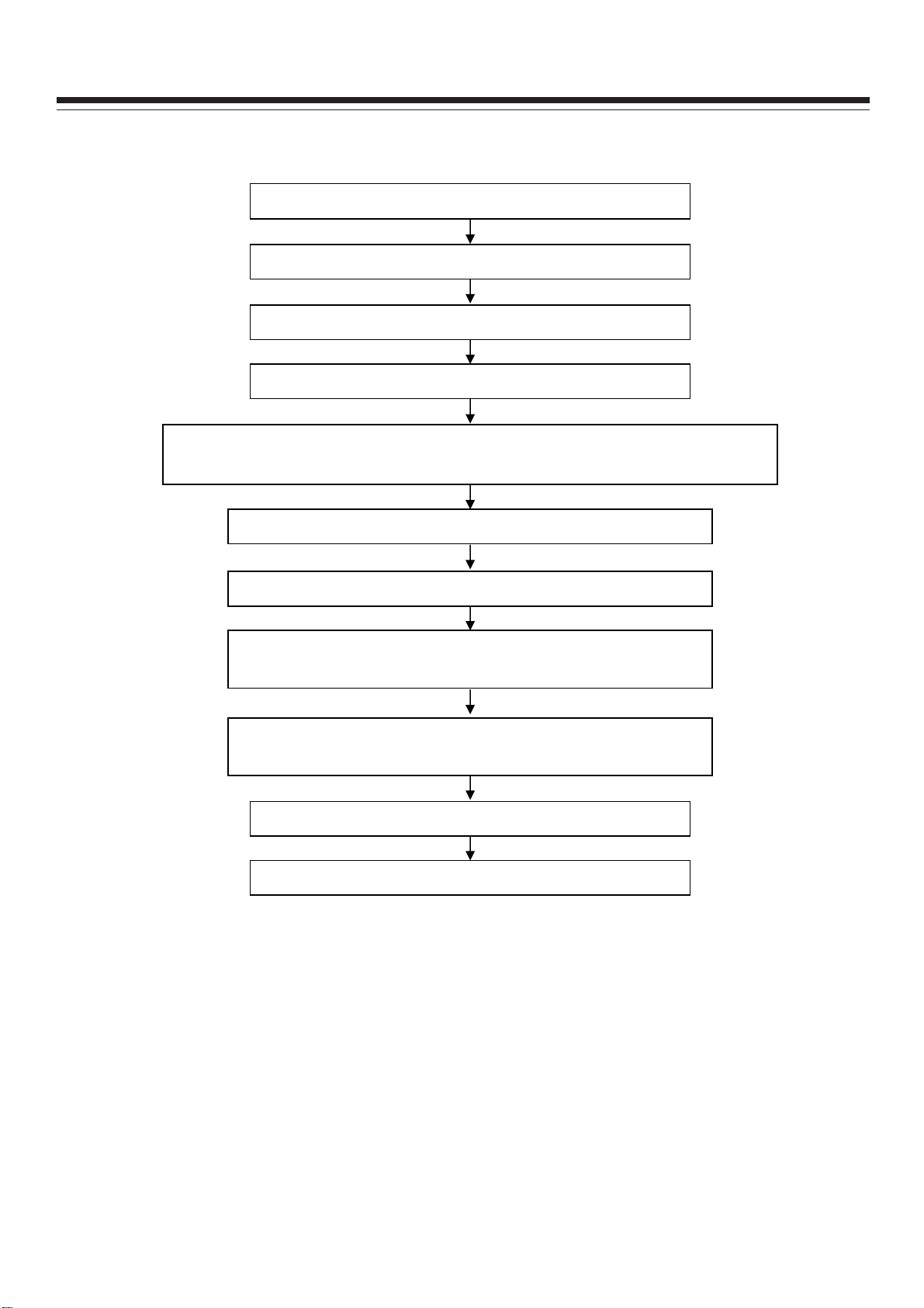
2.2 Alignment flow-chart
The alignment flow-chart is shown below (Fig. 1) :
Check if DDC, FLASH is written?
Make Data Processing Board
Mounting alignment (Check if the voltage is 120V)
White balance alignment
Input test signal, check TV all performance (such as all programs are searched,
analog control, etc.). Check if headphone and speaker output normally.
Input AV/SVIDEO signal, check if the AV jacks perform normally.
Input HD signal, check if YPbPr jacks perform normally.
Input VGA signal, check if the display is normal. Check all
performance (analog control), H-center, V-center, etc.
Input HDMI signal, check if the display is normal. Check all
performance (analog control), H-center, V-center, etc.
Ex-factory preset
Check accessories, packing
Fig.1 Alignment flow-chart
3. Alignment instructions
3.1 The whole unit alignment
3.1.1 According to the wiring diagram, connect Data Process Board, Power Board, Key board, IR
Board. Connect AC 120V power and turn on the TV, check if the display is normal.
3.1.2 The way to use Factory Menu
a) Press INPUT button, then in turn press “2”, “5”, “8”, “0” to enter the Factory Menu.
b) Press CH+ or CH- to select items, then press OK to enter.
c) Press CH+ or CH- to move the highlight up or down.
d) Press VOL- or VOL+ to adjust the selected item.
e) Press MENU to return to the previous menu.
f) Press EXIT to close the Factory Menu.
6
Page 8
g) After closing the Factory menu, you can press SLEEP to enter the Factory Menu directly if power
is still on.
h) In Factory Menu, select “On” for “Aging Mode” to turn on aging mode. Press any button on the unit
to exit.
i) “Power on mode” item of “Otherseting” has three options: “On” means power on directly; “Off”
means the unit will be in “standby” state when connect the power supply, and needed to press
“power” button to turn on; “Memory” means the unit will in the last power-off state after power-on.
3.2 White balance adjustment
3.2.1 Preparations
Before white balance adjustment, let the TV work for more than 30 minutes and be in stable status.
Use Color Analyzer CA210 BBY channel for alignment. Only align NORMAL color temperature. To
ensure both COOL and WARM color temperature to be able to meet the requirements, please make
sure bright step color temperature to be △X≤±5,△Y≤±5, dark step color temperature to be
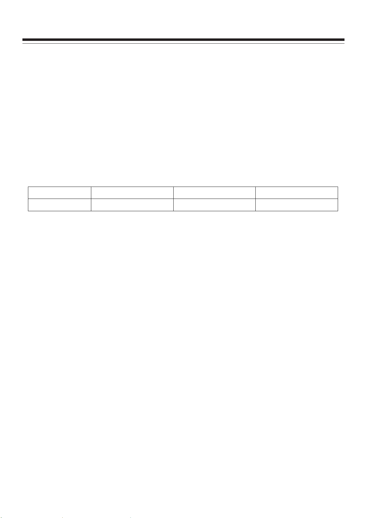
△X≤±5,△Y≤±5. Below table shows the color temperature for all models:
Model Cool Normal Warm
26”/32”/37”/42”/46” 12000K (272,278) 9300K (285,293) 6500K (313,329)
ALIGNMENT INSTRUCTIONS
Table 7 Color temperature for all models
Below white balance adjustment takes 42” model as an example. For other models, use the above
data as a reference for alignment.
3.2.2 White balance data alignment at four modes
a) Alignment at ATV mode (AV and S-VIDEO is the same)
In TV mode, set Air/Cable to Air. Input test signal with 11 gray steps. From Factory menu select “Color
Temp” item and set “Color Mode” to “NORMAL”, fix GAIN GREEN, adjust GAIN RED and GAIN BLUE
to make 9th step color coordinate to be (285, 293). Fix OFFSET GREEN, adjust OFFSET RED and
OFFSET BLUE to make the third step color coordinate to be (285,293). In this way repeatedly adjust
GAIN RED, GAIN BLUE and OFFSET RED, OFFSET BLUE until two level gray step’s color
coordinate be (285,293). Then select “MENU” to return to previous menu or select “SAVE TO
EEPROM” to save the white balance.
Check if COOL and WARM color temperature meet the requirement. If not, then adjust GAIN RED,
GAIN BLUE, OFFSET RED, OFFSET BLUE to make them meet requirements, and then save.
b) Alignment at DTV mode (HDMI is the same)
In TV mode, set Air/Cable to Air. Input test signal with 11 gray steps. From Factory menu select “Color
Temp” item and set “Color Mode” to “NORMAL”, fix GAIN GREEN, adjust GAIN RED and GAIN BLUE
to make 9th step color coordinate to be (285, 293). Fix OFFSET GREEN, adjust OFFSET RED and
OFFSET BLUE to make the third step color coordinate to be (285,293). In this way repeatedly adjust
GAIN RED, GAIN BLUE and OFFSET RED, OFFSET BLUE until two level gray step’s color
coordinate be (285,293). Then select “MENU” to return to previous menu or select “SAVE TO
EEPROM” to save the white balance.
Check if COOL and WARM color temperature meet the requirement. If not, then adjust GAIN RED,
GAIN BLUE, OFFSET RED, OFFSET BLUE to make them meet requirements, and then save.
7
Page 9

c) Alignment at YPbPr mode
First perform ADC calibration: input 75% color bar plus gray step signal in 480i/60Hz format, (VG848
Timing is 968, PAT is 918), enter Factory Menu select ADC Setting, do ADC AUTO adjustment once.
White balance adjustment: From VG848 equipment input 8 gray steps signal in 1920 x 1080i /60Hz
format. Enter Factory Menu select “Color Temp”, first set “Color Mode” to NORMAL, fix GAIN GREEN,
adjust GAIN RED and GAIN BLUE to make the 7th color coordinate be (285, 293). Fix OFFSET
GREEN, adjust OFFSET RED and OFFSET BLUE to make the second step color coordinate be (285,
293). In this way repeatedly adjust GAIN RED, GAIN BLUE and OFFSET RED, OFFSET BLUE until
two level gray step color coordinate be (285, 293). Then select “MENU” to return to previous menu or
select “SAVE TO EEPROM” to save the white balance.
Check if COOL and WARM color temperature meet the requirement. If not, then adjust GAIN RED,
GAIN BLUE, OFFSET RED, OFFSET BLUE to make them meet requirements, and then save.
d) Alignment at VGA mode
First do ADC calibration: input VESA crosshatch signal in 800 x 600 / 60Hz format (VG848 Timing is
854, PAT is 914), check if the picture is displayed wholly. If not, perform AUTO adjustment by making
use of VGA Setting sub-menu from SETUP menu (User menu) so that the picture is displayed wholly.
Then enter Factory Menu select ADC Setting, do ADC AUTO adjustment once to calibrate ADC.
White balance adjustment: From VG848 equipment input 8 gray steps signal in 800 x 600 /60Hz
format. Enter Factory Menu select “Color Temp”, first set “Color Mode” to NORMAL, fix GAIN GREEN,
adjust GAIN RED and GAIN BLUE to make the 7th color coordinate be (285, 293). Fix OFFSET
GREEN, adjust OFFSET RED and OFFSET BLUE to make the second step color coordinate be (285,
293). In this way repeatedly adjust GAIN RED, GAIN BLUE and OFFSET RED, OFFSET BLUE until
two level gray step color coordinate be (285, 293). Then select “MENU” to return to previous menu or
select “SAVE TO EEPROM” to save the white balance.
Check if COOL and WARM color temperature meet the requirement. If not, then adjust GAIN RED,
GAIN BLUE, OFFSET RED, OFFSET BLUE to make them meet requirements, and then save.
4. Performance check
4.1 TV performance
Input RF signal, first enter into CHANNEL menu, then perform Auto Scan to check if all programs can
be found, the speaker output normally, picture is displayed normally. Pay special attention that both
NTSC and ATSC signals are found.
4.2 Checking AV/S-Video jacks
Respectively input signal from AV/S-VIDEO jacks, check if the picture and sound are normal.
4.3 Checking YPbPr/YCbCr jacks
Input YUV signal (from VG848 signal generator), respectively input all formats of YUV signal which is
shown at below (Table 8) to check if the display and sound are normal.
ALIGNMENT INSTRUCTIONS
Table 8 YUV signal formats
# Resolution
1 720×480i@59.94/60 Hz 15.734 59.94/60 13.5 480i(59.94/60p)
2 720×480p@59.94/60 Hz 31.469 59.94/60 27.00 480p(59.94/60p)
3 1280×720p@59.94/60 Hz 44.96 59.94 74.18 720p(59.94/60p)
H-freq.
(kHz)
V-freq.
(Hz)
8
Dot-Clk Freq.
(MHz)
Remarks
Page 10
ALIGNMENT INSTRUCTIONS
4 1920×1080i@59.94/60 Hz 33.75 59.94 74.25 1080i(59.94/60i)
5 1920×1080p@23.98/24 Hz 27.00 23.98/24 74.25 1080p(23.98/24p)
6 1920×1080p@59.94/60 Hz 67.50 60.00 148.50 1080p(59.94/60p)
4.4 Checking VGA jack
Input VGA signal (VG848 signal generator),respectively input all formats of VGA signal which is
shown below (Table 9). Check if the display and sound are normal. If the picture has deflection in size
and position, then enter into user menu of Setup, from VGA Setting sub-menu perform AUTO
adjustment to correct the picture automatically.
Table 9 VGA signal formats
# Resolution H-fre. (kHz) V-fre. (Hz)
720×400@70 Hz 31.47 70.08 28.32 DOS
1
640×480@60 Hz 31.50 60.00 25.18 VESA
2
800×600@60 Hz 37.90 60.00 40.00 VESA
3
1024×768@60 Hz 48.40 60.00 65.00 VESA
4
1280×1024@60 Hz 63.98 60.02 108.00 Only for 37”/42”/46” model
5
1360×768@60 Hz 47.71 60.01 85.50 Only for 26” and 32” model
6
1920×1080@60 Hz 67.16 59.96 173.00 Only for 37”/42”/46” model
7
Dot-CLK
freq. (MHz)
Remarks
4.5 Checking HDMI jack
Input HDMI signal (VG849 signal generator), respectively input all formats of signal shown at Table 8.
Check if the display and sound are normal.
5 User menu preset
Enter into Factory menu, select and do Other Setting→SHIPMENT item, then the TV will automaticlly
preset the user menu to default. After alignment this User Menu Preset procedure must be done.
SHIPMENT will do the following :
1) Clear all program information
2) Clear V-CHIP information
3) Analog value default setting for all sources
4) Power on mode set to Off
5) Active Setup Wizard menu
Note: after the Preset procedure is complete, it must exit the menu, power off at Standby state and
then disconnect the power supply.
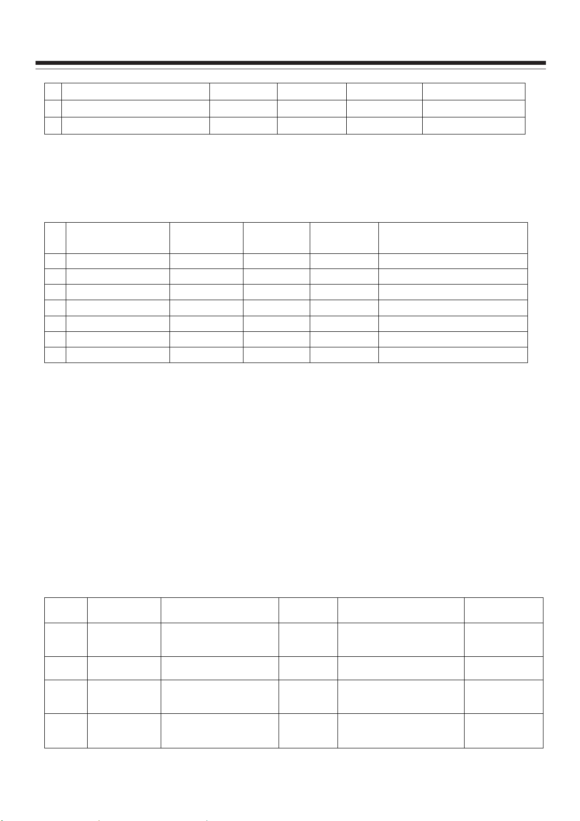
6. Software writing instructions are shown at below (Table 10)
Table 10 Software writing instructions
# Part No. Model
NS04 5272532005 MX25L3205DM2C-12G
NS03 5272404002 AT24C04IV-10SU-2.7
Software
function
Main
software
HDCP
KEY
Method Remarks
Write with instrument like
ALL11. Write-protection is
needed.(See below note)
Write with instrument like
ALL11
For all models
For all models
NB01 5272402002 AT24C02BN10SU-1.8 VGA EDID
NA05 5272402002 AT24C02BN10SU-1.8
HDMI1
EDID
9
Write with instrument like
ALL11
Write with instrument like
ALL11
For all models
Only for
32”/37”/42”/46”
models
Page 11

ALIGNMENT INSTRUCTIONS
Only for
32”/37”/42”/46”
models
Only for 26”
model
NA04 5272402002 AT24C02BN10SU-1.8
NA07 5272402002 AT24C02BN10SU-1.8
NA04 5272402002 AT24C02BN10SU-1.8
NA07 5272402002 AT24C02BN10SU-1.8
HDMI2
EDID
HDMI3
EDID
HDMI1
EDID
HDMI2
EDID
Write with instrument like
ALL11
Write with instrument like
ALL11
Write with instrument like
ALL11
Write with instrument like
ALL11
Note:
To set write protection, the method is : enter into ALL-100 writing program AUTO interface, select
Config item (it must be selected when writing). In AUTO interface, click Config Setting, set Protect to
All Protect, SRWD to Enable. Pay attention that every time when ALL-100 writing program is
reopened, write-protection must be set again.
7. EEPROM initialization (not be used unless needed)
The method is: press IR POWER/KEYPAD POWER to turn on the TV, before showing LOGO press
INPUT SOURCE incessantly until the indicator lights red, then in turn press MENU, VOL+, CH+ (the
interval between two press is below 2 seconds), the indicator light will turn blue, after a while the unit
will be in STANDBY, that means RESET EEPROM succeeds. If error key order or key number or the
interval is over 2 seconds, the unit will keep on the previous setting and perform the order, then
EEPROM will not be cleared
10
Page 12

This series’ TV chassis provides two software upgrade ports, one is SERVICE PORT, the other is
RS232 jack. To use SERVICE PORT, only a USB device is required and the speed is faster, so it is
recommended to use the SERVICE PORT. To use RS232 jack, the speed is slower, and more devices
are required such as a PC, a set of fixture for upgrade and upgrade software. It is recommended that
only SERVICE PORT fails in upgrade, then use RS232 jack.
Software Update Instructions
A. Making use of SERVICE PORT for upgrade
Copy file with extension name of BIN (*.BIN) for upgrade to the USB device, save it at root catalog. To
upgrade different TV model, the adopted files are different. It is required to correctly name the *.BIN
files, and below table lists the TV models and file names for your reference.
Model Panel type Part No. Software name
DX-19L150A11 CPT 9219KS7001 LC19KS70CPT.BIN
DX-22L150A11 CPT 9222KS7001 LC22KS70CPT.BIN
DX-24L150A11 CMO 9224KS7001 LC24KS70CMO.BIN
DX-26L150A11 AUO 9226KS7001 LC26KS70AUO.BIN
DX-32L150A11 AUO 9232KS7001 LC32KS70AUO.BIN
DX-37L150A11 AUO 9237KS7001 LC37KS70AUO.BIN
DX-40L130A11 SHARP 9240KS7001 LC40KS70SHARP.BIN
DX-46L150A11 AUO 9246KS7001 LC46KS70AUO.BIN
Method 1:
1. Disconnect the AC power, insert USB device into the SERVICE PORT.
2. Reconnect the power, the TV will automatically upgrade the software. It will take some minutes.
During the process, the power indicator will flicker in red and blue. After completion, the TV will auto
power on and the power indicator lights blue. If the process takes more than 5 minutes, that means the
upgrade fails. Please check the BIN format file and USB device again.
3.When upgrade completed, remove the USB device, disconnect the AC power and then reconnect
the power. The SERVICE PORT upgrade is finished completely.
Method 2:
1. Connect the power. Insert the USB device into the SERVICE PORT.
2. Enter into Factory menu, access SW Upgrade option. The TV will automatically scan the USB
device and files in BIN format. If USB device is normal and BIN file is correct, the TV will upgrade by
itself. If fails, then check BIN file and USB device again.
3. When upgrade completed, remove the USB device, disconnect the AC power and then reconnect
the power. The SERVICE PORT upgrade is finished completely.
11
Page 13

Software Update Instructions
B. Making use of RS232 for upgrade
Tips: A PC and the upgrade fixture designed for this KS# chassis are required. Use Mstar on-line
writing tool – Mstar ISP Utility, the needed time is longer.
1. Power on the TV, connect the upgrade fixture correctly, open the upgrade software, click “Connect”
icon. If the connection fails, the following screen will appear.
2. Click “Config” icon (see below figure). Adjust “ I2C Speed Setting” option, lower the setting of
“Speed”. Then click “Connect” icon again.
Wait until right connection information appears which is shown below.
12
Page 14

3. Click “OK” , then click “Device” (see below figure).
Software Update Instructions
Mark “WP Pin pull to high during ISP” option.
Mark “New Setting Below” option.
Mark Bit7,Bit5,Bit4,Bit3,Bit2 from “Status Register” option. That is, the value of “Register Setting
Value” should be “BC”.
4. Click “Read” icon, download upgrade software which is shown below.
13
Page 15

5. Click “Auto” .
Software Update Instructions
Mark “Erase Device” option, select “File Area”.
Mark “Blank”, “Program”, “Verify”, “Exit ISP” options.
Click “Run” button, on the right will appear information of upgrade hints. When “Pass” appears, that
means the upgrade is successful.
6. After completion, disconnect the power then reconnect it. The upgrade is finished now.
14
Page 16

The analog and digital RF signal received by antenna will be sent to integrative tuner
TUNER2(DA58GT-13-E, contains HF and IF amplifier circuits), which selects appropriate channel and
sends the selected IF signal to the next level by the control of SDA, SCL.
The analog RF signal sent to tuner, via high amplify and mixed frequency to get IF signal VIF,
then it will be divided into two ways, one way will be sent to acoustic surface-wave ZF3 to IF filter and
get better IF characteristics, then it will be sent to NF1(M61111FP) through pin20, 21 to do
intermediate amplification, phase-locked loop VCO and synchronous wave detection and output
VIDEO-TV(ATV) from pin1; another way will be sent to acoustic surface-wave ZF4 to IF filter and gent
better IF characteristics, then it will be sent to NF1(M61111FP) to do intermediate amplification
and wave detection and output SIF from pin10.
The digital RF via high amplify and mixed frequency in the tuner, output deferential digital IF
signal from pin10、11, the signal will be sent to the main IC NS01(MSD319EL) to do intermediate
amplification and demodulation, then demodulate the transform stream TS which contains video/audio
Working Principle Analysis of The Unit
and other information.
ATV, SIF, TS, audio/video signal of AV, S-VIDEO, VGA and HDMI. Component video signal
selected by switch NB09(PI5V330W) from Component 1 and Component 2, Then one of video signal
selected by switch NB10(PI5V330W) from Component and VGA . AV, S-VIDEO ,Component audio
signal selected by switch NB11 (HEF4052BT), HDMI audio/video signal selected by internal switch
from HDMI1, HDMI2, HDMI3; all of the signals will be sent to the main IC NS01(MSD319EL) switch
select, video decode and process.
In MSD319EL, TS of DTV via TS demultiplex, distinguish the different programs and pick-up the
corresponding audio/video stream and data stream, after MPEG-2 uncompress, video coder and
audio D/A transform, recover the analog video signal YCbCr and audio signal L/R.
ATV output from M61111FP will be sent to MSD319EL video switch, A/D convert and digital
decode. The video selected by switch embed in MSD319EL will be sent out in two ways: one is sent to
decode and process; the other is Video OUT.
All of the video data (include DTV video) via switch select, video decode and process will be
sent to MSD319EL to do D/A transition, image scale, OSD superposition, then LVDS conversion to
signal acceptable for LCD panel, namely four pairs of low differential signal and one pair of clock
signal, then it will be sent to LCD panel for picture display.
All of the audio signals will be sent to MSD319EL to do audio switch selection and sound effect
processing, then output L/R to sound amplifier NV03 (R2S15112FP) amplifying to speaker. The audio
L/R also sends to Audio OUT.
The unit is control by the MCU built in MSD319EL, it connects TUNER and E2PROM through
IIC bus line and controls the whole unit working.
15
Page 17

Block Diagram
12V、5V、3.3V、1.8V、1.2V、STB5.0V
VGA AUDIO
OTHER AUDIO
INPUTS
TNUER
FA2316
AV 1
AV 2
YPbPr 1
VGA
POWER
IF
YPbPr
RGB
AUDIO SWITCH
HEF4052BT
ANOLOG DEMO
M61111FP
VIDEO SWITCH
PI5V330W
DIF
IIC
DDR SDRAM
K4T51163QG-HCF7
AUDIO
CVBS
SIF
Video
Y-C
MX25L3205DM2C-12G
MSD319EL
SPI FLASH
LVDS
IIC
HP AMP
BH3547F
Panel
HDCP KEY
AT24C04IV
AMP
R2S15112PF
HP
SPEAKER
SVIDEO 1
HDMI 1
HDMI 2
HP AMP
BH3547F
SERVICE PORT
RS232
Audio out
Video out
SPDIF
16
Page 18

1. no picture and no sound
Connect the power and
check if the red
indicator lights at
STANDBY?
Y
N
Check if 5V of X603
3# on the main board
inputs normally?
N
N
Check STANDBY
circuit on the power
board
TROUBLESHOOTING GUIDES
Press POWER button
on the unit or remote
control, does the
indicator turn blue?
N
Check if the voltage of
X601 pin1 on the main
board is high?
Check the power board
N
Y
Check if the voltage of
Y Y N
X601 pin13 on the
main board is high?
N
Check NS01 and its
Y
peripheric circuit
Is 24V on the power
board normal?
Y
Check the backlight
board
Check the power board
17
Page 19

2. no picture
Replace the main
board
N
TROUBLESHOOTING GUIDES
Replace the main
board
Initialize EEPROM in
N
factory menu, then power
off, check if picture is
normal after restart?
N
N
Y
No picture
Y
Can the unit be operated
by remote control or
keys on the set?
Y
Is there any backlight?
Y
N
Display OSD normally
when press MENU
button?
Y
Y
No picture from all
sources?
N
Replace the main
Y
board
Is there 24V on the
Y
power board?
Y
IF X601 pin4/pin5 on
main board is
high-level
Y
Check the panel
backlight
N
Check the power board
N
Check the main board
18
Page 20

TROUBLESHOOTING GUIDES
Adjust the main board
again
N
Which channel is no
picture?
TV
Measure NF1 pin1, is
there 1-1.5 VPP signal
or noise wave?
N
Check if the output
from TUN2 pin12 is
normally?
Y
Check NF1 and its
peripheric circuit
OTHER
Y
N
Replace the main
board
Replace the main
board
Check TUN2 and its
peripheric circuit
19
Page 21

3. no sound (take TV as an example)
p
/
p
No sound
Y
Check if the voltage of
X602 pin4/pin5 is
normal?
Check the power board
N
TROUBLESHOOTING GUIDES
Check if there is wave
Y
inputted to NV03
in12
in25?
N
Check if there is wave
outputted from NV01
pin1/ pin7?
N
Check if wave output
from NS01pin63/pin64
is normal?
N
Is there 4.5M wave
inputted from NS01
pin51/pin52?
Y
Y
Y
Y
Check NV03 and its
peripheric circuit
Check NV01 and its
peripheric circuit
Check NS01 and its
peripheric circuit
20
Page 22

TROUBLESHOOTING GUIDES
Is there IF 45.75M
outputtd from
TUNER2 pin12?
Check TUNER2 and
its peripheric circuit
N
Y
Check NF1 and its
peripheric circuit
N
21
Page 23

Wiring Diagram
14pin
PANEL
12pin
13pin
5pin
30pin
30pin XS02
13pin X601
40pin XS01
5pin X602
MAIN BOARD
2pin X124
635KS00100
KEY BOARD
6KU00320B0
POWER & BACKLIGHT
4pin X122
4pin XV02
6KS0090110
IR BOARD
635KS00101
Page 24

POWER & BACKLIGHT
page1 of 5
Page 25

IR&KEY&TUNER
page2 of 5
Page 26

5V_HDMI-1_IN
INTERFACE CIRCUIT
page 3 of 5
1K
RA04
RA02
1K
VA02
HOTPLUG_HDMI-1_OUT
0
RA25
1K
RA26
HOTPLUG_HDMI-3_OUT
BC847AW
HDMI_1
NC
BC847AW
VA05
10K
RA31
1K
NC
18
16
14
12
10
8
6
4
HDMI
R859
HDMI_2
AV1 INYPBPR
XB21
AV13-06-535
VGA AUDIO
JY-3541L-01-030
5V_HDMI-1_IN
19
177
15
13
11
9
5
3
2
1
XA02
5V_HDMI-3_IN
1K
RA32
VA04
BC847AW
19
18
177
16
15
14
13
12
11
10
9
8
6
5
4
3
2
1
XA04
HDMI
Y1
W1
R1
G2
B2
R2
NB03
PESD5V0L4UG
G
R
L
XB02
5V_HDMI-1_IN
5
PESD5V0L4UG
5V_HDMI-3_IN
5
2
3
4
1
330p
330p
DA01
MMBD1204
4
3
2
NA02
+5V
DA03
4
3
2
NA06
PESD5V0L4UG
5
RB03
10K
CB03
RB04
10K
CB04
+5V
1
NA10
NA11
5V_HDMI-3_IN
MMBD1204
1
YIN
PBIN
PRIN
100n
CB06
12K
12K
RB10
RB11
RA05
NA12
RA33
10K
NC
10K
NA13
5
560p
560p
10K
RA34
CB82
100n
CB10
CB11
CA02
NA14
10K
4
RA07
100n
NC
5.1
5.1
5.1
5.1
5.1
5.1
5.1
5.1
NA15
NA16
NC
CA04
100n
5.1
5.1
5.1
5.1
5.1
5.1
5.1
5.1
NB22
PESD5V0L4UG
1
3
2
10K
RA50
5
6
7
8
10K
RA51
RA10
RA11
RA12
RA13
RA14
RA15
RA16
RA17
NA17
HDMI_CEC_0
10K
RA54
10K
RA55
RA35
RA36
RA37
RA38
RA39
RA40
RA41
RA42
AV2 IN
VGA_LIN
SDA
SCL
WP
Vcc
SDA
5
SCL
6
WP
7
Vcc
8
SGMI2012-2R2KT
CB81
220p
CB78
330p
CB79
330p
Y
W
R
AV3-14WKD
VGA_RIN
NA04
24C02N-10SI27
NA07
24C02N-10SI27
LB11
2.2uH
CB85
220p
10K
RB84
12K
RB87
560p
10K
RB86
12K
560p
RB88
@pinCo
@pinCo
@pinCo
XB03
GND
A2
A1
AO
RA27
GND
0
A2
A1
AO
CB83
CB84
4
3
2
1
VA03
4
3
2
1
75
RB90
+5V
D
2N7000
RA28
5
CB72
100n
SDA_HDMI-1
SCL_HDMI-1
HDMI_CEC_0
HDMI-1_RXCHDMI-1_RXC+
HDMI-1_RX0HDMI-1_RX0+
HDMI-1_RX1HDMI-1_RX1+
HDMI-1_RX2HDMI-1_RX2+
STB_3.3V
27K
G
S
0
SDA_HDMI-3
SCL_HDMI-3
HDMI_CEC_0
HDMI-3_RXCHDMI-3_RXC+
HDMI-3_RX0HDMI-3_RX0+
HDMI-3_RX1HDMI-3_RX1+
HDMI-3_RX2HDMI-3_RX2+
4
3
2
NB20
PESD5V0L4UG
RA29
RA30
100
AV1_VIN
AV1_LIN
AV1_RIN
1
CB70
330p
CB71
330p
NC
HDMI_CEC
10K
RB80
10K
RB81
CB73
220p
RB82
12K
12K
RB83
SGMI2012-2R2KT
LB10
2.2uH
CB77
220p
CB74
560p
560p
CB75
S_VIDEO
3.3V_Normal
10K
RB113
75
RB85
DIN-017
XB23
S
C
Y
G
G
G
3.3V_Normal
10K
RB112
RB114
1K
VB16
BC847AW
0
RB115
XB01
VGA
HC1038-15F-3.08
NC
5
10
15
89
234
12 13 14
1
67
11
W1 R1 W2 R2
L1
R1
AUDIO OUT
L2
R2
YPbPr_SOUND
XB04
RCA-410A-10
AV2_VIN
AV2_LIN
UBA-100/W
AV2_RIN
USBUPDATE
6
5
1
2
100n
SV_DET
PESD5V0L4UG
1
6
NB05
1
2
3
4
NB04
PESD5V0L5UY
100n
34
CB01
2
5
ZB01500MHz
ZB02500MHz
500MHz
ZB03
1
3
4
2
6
10p
CB05
RB09
75
5
CB08
10p
CB76
4
2
PESD5V0L4UG
100n
5
XA01
34
2
1
1n
C693
10u
C667
GG
R736
100K
FU1
SMD1206P075TF
750mA
C666
100n
NA53
R634
5.1
R633
5.1
NA54
4
NA08
3
CA05
5
22K
RB17
CB12
RB1375
75
10p
AOUTL1
CB86
10uF
16V
10uF
16V
CB87
1
3
NB21
330p
330p
L629
STPB3216-310PT
TSM2301CX
D
V606
NC
HOST_1DP
HOST_1DM
100n
22K
RB16
G
CA06
CB13
RB21
AOUTR1
CB51
CB52
S
RA44
100
100
RA45
NC
SGMI2012-2R2KT
CA07
220p
SGMI2012-2R2KT
2.2uH
LA01
220p
RB22
100
100
RB23
CB14
1u
CB15
1u
CB16
1u
1
4
3
2
NB12
100n
5VUSB
NC
R643
R737
C694
100n
R738
BC847AW
CB53
0
10K
1K
V607
LA02
2.2uH
220p
CB90
1u
RB68
RB69
5
CA08
22K
10K
10K
+5V
RB92
22K
R739
CA09
75
RB95
0
1K
4
220p
RA43
VS_RGB
HS_RGB
DDC_SCL
DDC_SDA
VGA_B
VGA_G
VGA_R
CB89
1u
RB77
R644
V608
BC847AW
NC
12K
10K
R740
75
3
RA46
12K
2
5
IN2
GND
4
CB63
RB78
1
SVEDIO-Y
SVEDIO-C
+5V
DB01
MMBD1204
CB96
16V
47uF
6
BIAS
OUT2
IN1
MUTE
3
MUTE_EOP
560p
560p
R741
1K
X605
7
2
CB64
USB_ON
8
VCC
OUT1
1
5V_STB
1
2
3
4
BH3547F
STPB3216-310PT
47p
C801
NB01
24C02N-10SI27
AO
A1
A2
GND
LB15
STPB3216-310PT
16V
100n
CB100
CB99
10uF
NB24
HD1_LIN
HD1_RIN
5V_EOP
DRAWN BY
APPROVED BY
L801
100n
C803
C804
0
R801
0
R802
47p
C802
CB02
100n
8
Vcc
7
WP
6
SCL
5
SDA
NC
I2C_UPDATE
DDC_SCL
DDC_SDA
HKTX179DA
SPDIF
NB02
N801
MAX3232CSE
47u
RB01
0
16
16V
Vcc
15
GND
14
T1OUT
13
R1IN
12
R1OUT
11
T1IN
10
T2IN
9
R2OUT
100
100
NC
10K
10K
10K
Vcc
IN
GND
RB07
RB02
FOR SOFTWARE UPDATE,WHEN ISP IS HIGHT
R821
0
V822
BC847AW
YES
0
R820
V821
BC847AW
V820
BC847AW
2
1
3
RB12
RB14
100
100
RB15
RB108
RB109
R822
R823
2.7K
R824
510
R825
2.7K
R826
510
R827
YES
NC
T2OUT
22
22
C1+
C1-
C2+
C2-
R2IN
YES
10K
RB05
TITLE: DWG NO.
Interface
Circuit
1
2
V+
3
4
5
6
V-
7
8
DDC_SCL
DDC_SDA
RXD_UPDATE
5V_STB
TXD_UPDATE
CB07
100n
RB08
100
10K
RB06
REV.
Sheet to
XIAMEN OVERSEAS CHINESE
ELECTRONIC CO., LTD.
C805
100n
100n
C806
C807
100n
100n
C808
TXD_UPDATE
RXD_UPDATE
5V_STB
1K
J820
LL4148
R828
D820
PORT_UPDATE
LB01
STPB3216-310PT
47u
16V
CB09
+5V
SPDIF_O
9226KS7001DL
A1.0
1
5
XOCECO
Page 27

POWER
page 4 of 5
Page 28

MSD319
page 5 of 5
Page 29

B-ON
PWM
GND
12V
12V
32V
GND
GND
5V-1
GND
5VSTB
GND
P-ON
24V
24V
GND
GND
GND
R
GND
GND
L
KEY
GND
X124
LED
GND
5V
IR
1
X601
X122
1
VA02
RB08
3.3V
GND
4
R622
DV03
110
INT
1
X604
C660
13
1
R62A
RA17
LV03
LV02
DV04
RV07
R851
C661
C602
L601
8
5
C610
L603
L608
C606
L609
C635
C633
R616
C637
C640
V602
R621
RS02
RS11
CV16
2536
RV06
24
13
CB06
RV13
CS65
RB10
CB10
CB03
RB03
1
3
NB03
L801
R828
CV07
V821
R820
J820
5
4
CV15
V820
CS64
CB11
RB11
CB04
XB02
VV03
RV09
R825
R823
R827
R830
RV05
R829
R822
V822
R824
RB04
RV10
RV08
R821
R646
DV01
CV25
CV24
12
R604
R603
C605
C609
RA10
5
NA02
NA11
NA12
RA11
4
31
19
L602
C632
L610
CV30
CV20
CV18
RA13
RA12
NA14 NA15
NA13
C671
XA02
R618
V603
R620
37
48
1
CV05
R717
VV02
DV02
RA14
RA15
NA16 NA17
N602
C670
RV11
RV02
R718
4
RA16
R632
C615
R719
L614
C613
R614
13
R680
L607
R635
5
X602
1
CV31
4
XV02
CV28
1
4
CV29
1
RA02
CV04
RA04
NA10
CB09
NB02
C663
CV08
VV01
RV04
CV26
1
C601
C634
C648
RV01
NV03
R826
DA01
RA44
RB17
RB22
RB23
RB21
C620
C626
RA07
RA05
CV13
RA45
D820
3
1
4
C641
4
5
CV11
CV06
1
4
C621
2
N603
C644
C650
C647
N607
D602
NA04
RA50
CV10
CV14
RV12
C801
C802
1
3
46
XB01
8
5
RA51
1
X605
1
4
N601
R626
1
8
CA02
L604
R690
C652
R625
R623R624
DB01
R608
C607
C653
NS03
4
C804
58
R607
RS53
L620
C651
C646
5
RS52
8
5
10
C625
C619
C622
D601
C624
C806
1
1
8
CS75
CB01
NB04
16
3
L622
C682
C803
1
C805
C616
R609
R602
R856
R601
L605
N605
RS54
R855
C807
C614
L613
RS58
RB01
RS57
R801
N604
RS16
CB12
R610
R611
C628
4
C617
NB01
RB02
N801
RB16
C627
DS01
RS13
VS01
CS36
R802
CB14
4
5
C611
CB15
1115
CB02
3
1
R696
V605
C623
LS09
CS99
RB12
RB15
RB13
1
C636
2
RS18
9
8
6
R695
RS19
RB07
RB14
CB08
L606
CS42
CB05
3
ZB01
RB09
C612
C618
ZB02
NB05
CB16
CA05
V601
R612
RS10
ZB03
CB13
R728
RB108
RB109
R727
C808
3
4
NA08
L612
L611
R615
RB112
VB16
1
6
ICTLQCAOI
R699
RB113
RB114
LB03
RB47
C654
C638
C672
CB40
8
RB49
CS08
D603
V604
CB39
9
1
4
R698
R648
VS02
RB46
DDC
C655
N609
RB53
RB48
R619
N608
RB211
NB10
RB210
R629
R627
R628
R649
RS33
RS35
RS34
RB50
5
C642
CS16
569KS06690 V2
TC BC
8
C643
C649
C645
R834
CS80
CS81
NS05
CS82
CS84
CS83
CS85
CS86
CS87
RS70
RS85
RS72
RS83
CS26
C658
C657
C659
C656
R630
R631
GS01
RS130
CS62
CS63
RS37
CS51
RS20
1
RB55
16
RA46
RA43
CA08
CA09
CA07
LA01
CA06
RB43
CB213
RB212
XB23
20090916
R735
LED1
RS123
RS122
R835
R837
RS121
RS73
CS90
RS71
CS89
RS79
1
2
3
7
RS115
8
9
RS114
ABCDEFGHJK M PLNR
RS113
RS112
CS88
C689
C690
RS86
RS87
185
RS111
RS110
193
195
205
215
RS84
225
235
245
255
256
1
5
CS46
CS47
CS49
CS50
RS22
RS25RS26
CS45
CS48
CS44
RS21
RS23
RS24
CB41
CB19
RB25
CB23
RB90
CB85
CB25
CB81
CB29
CB26
NB22
LB11
NB06
RB29
CB17
RB24
CB18
LA02
5
1
G2 B2
Y1
VJ02
RS14
R741
RJ10
RJ14
RS12
RJ08
RS81
RS88
RS82
RS89
K1
CV12
CV09
CS110
R647
14
NS04
1
510
12
CF32
RB74
LF7
RB73
CB55
CB54
CB90
CB89
RB95
RF42
RF41
XB04
RF39
RF38
TOP
VB12
RB101
CV03
8
5
NF1
CF20
LF4
R715
R716
TUNER2
RB100
CV02
CS76
5
CV01
CF2
RS04
V608
RJ15
VJ03
RJ16
VJ01
RJ09
L621
RV03
CB98
RB98
14
NV01
8
CV17
NA07
1
4
CA04
RA33
RA42
RA40
RA38
RA36
R859
RA31
RA25
RA26
CF13
24
LF2
20
13
CF25
CF3
RF24
CF12
RF28
CF18
RF30
DB10
RA41
RA39
RA37
RA35
GF1
VA05
RF22
RA32
VA04
VF4
8
5
1
CF17
CF24
RF26
R739
VF3
RF23
RA54
RA55
ZF4
RV16
RV19
RV20
RV17
R868
CV19
ZF3
RF29
RF27
VF1
RF2
RF5
V607
NA53
LV01
1
RF10
RF3
RF7
RF4
R740
R633
RA34
CF16
RF20
RF21
RF8
FU1
1
3
CF26
CF27
R738
R643
R644
5
1
CB72
RB82
CB74
CB57
CB73
RB85
CB77
LF1
RF16
RF1
CF28
RF9
ZF2
NA54
4
ZF1
CF4
RF14
R737
5
CB47
CB70
C694
CV21
NB20
RB80
CF6
RF17
V606
L629
R634
XA01
4
3
NA06
RB83
CF8
CF10
CF5
DA03
5
LB10
CB42
CF9
4
VF2
C667
NV02
110
RB81
19
CB75
CF11
XV03
CV27
3
1
CB71
RF12
CF15
LF3
CF1
RF13
CF23
RF19
R736
C693
C666
XA04
XB03
R
YW
R711
R710
C680
6
4
N612
R713
3
1
C679
R712
RS59
RS62
CS30
CS68
CS71
RS42
RS31
CS70
RS39CS01
CS69
CS43
RB61
RB60
RB66
RB57
CB48
CS61
CS60
CS59
8
CB45
CB58
9
LB05
CB96
CB100
RB78
CB64
4
1
NB12
5
5
CB76
NB21
W2
W1 R1
30
RB58
3
1
30P
RB65
NB11
RB64
CB99
RB92
XS01
RB62
39
40
LS08
RS68RS69
R840
CS79
C691
C683
RF43
CF36
RF44
CF35
1
16
NB24
4
5
1
8
CB86
CB87
R2
XS02
20101
VCC
1
5
15 25 35
RS65
RB71
RS66
CS27
GJ01
135
VB01
RS67
64
RB77
CB63
RS61
VCC
NS01
128
CS54
CB56
RB68
CB51
CB53
125
115
105
85
75
CS11
95
65
CS55
RS60
CS32
3
4
CS56
RS27
CB46
RB69
CB52
CS24
R726
C681
C692
CS66
RS41
RS40
CS67
CS58
XB21
RS28
LB15
2
VS10
10 20 30
RS91
RS90
RS78
R732
CS12
R733
CS40
C687
C688
C686
CS22
165
155
175
25
354555
15
RS29
CB83
CB44
RB87
CB60
CB82
RB72
RB86
RB84
RB88
CB79
CB78
CB84
VB02
4
31
3
4
5
R2
W1
R1
Page 30

CF22
CF19
RF25
CF21
BOTTOM
CF14
R867
CF30
CF33
C677
C676
R724
C674
CF7
R723
C675
CF34
CF31
RF11
RF18
1
C604
NS02
4
RS38
RS99
58
RS47
RS48
CS73
1
13 1
C639
RV21
RV22
R720
15
1
14
1
4
1
R697
R123
R124
C665
R104
V101
R101
R691
R694
C662
C116
R105
N610
VA03
RA28
R102
RA30
RA29
RA27
LS02
R617
LS05
39
40
30
RF15
RF6
LS03
CS03
LS07
L625
L627
CS23
L626
CS07
R645
CS38
CS74
CS09
RS46
20
R725
CS13
RS45
LS50
RS43
L624
C685
CS72
CS34
RS44
CS19
CJ30
CS04
R734
10
CS33
C684
CS57
CS31
RJ19
RJ12
CJ28
5
1
2
L623
LS06
RS30
LS04
CS28
CS15
CS21
RS32
CS39
CS29
CS02
CS20
RS64
C809
CS37
CS25
R841
L628
CS06
CS78
CS77
RS63
R729
15
25
35
R613
R842
1
CB07
RB06
RB05
LB01
1
6
11
5
10
15
Page 31

Exploded View Parts List
 Loading...