

Page 1

Dynex
Dynex
DX-19LD150A11
DX-19LD150A11
DX-22LD150A11
DX-22LD150A11
LCD TV/DVD Combo
LCD TV/DVD Combo
Service Manual
Page 2

COPYRIGHT
Dynex DX-19LD150A11 / DX-22LD150A11 LCD TV/DVD combo Service Manual
Original issue: May 2010
Page 3

Contents
1. Product safety servicing guidelines. . . . . . . . . . . . . . . . . . . . . . . . . . . . . . . . 4
Important safety notices. . . . . . . . . . . . . . . . . . . . . . . . . . . . . . . . . . . . . . . . . . . 4
Graphic symbol . . . . . . . . . . . . . . . . . . . . . . . . . . . . . . . . . . . . . . . . . . . . . . . . . 4
Service information . . . . . . . . . . . . . . . . . . . . . . . . . . . . . . . . . . . . . . . . . . . . . . 4
Implosion . . . . . . . . . . . . . . . . . . . . . . . . . . . . . . . . . . . . . . . . . . . . . . . . . . . . . . 5
2. TV components . . . . . . . . . . . . . . . . . . . . . . . . . . . . . . . . . . . . . . . . . . . . . . . . 6
Side controls . . . . . . . . . . . . . . . . . . . . . . . . . . . . . . . . . . . . . . . . . . . . . . . . . . . 6
Back connectors . . . . . . . . . . . . . . . . . . . . . . . . . . . . . . . . . . . . . . . . . . . . . . . . 7
3. Specifications. . . . . . . . . . . . . . . . . . . . . . . . . . . . . . . . . . . . . . . . . . . . . . . . . . 8
4. Calibration and adjustment. . . . . . . . . . . . . . . . . . . . . . . . . . . . . . . . . . . . . . 10
VGA ADC calibration . . . . . . . . . . . . . . . . . . . . . . . . . . . . . . . . . . . . . . . . . . . . 10
YPbPr ADC calibration. . . . . . . . . . . . . . . . . . . . . . . . . . . . . . . . . . . . . . . . . . . 11
5. Block diagram . . . . . . . . . . . . . . . . . . . . . . . . . . . . . . . . . . . . . . . . . . . . . . . . 12
6. Exploded diagram . . . . . . . . . . . . . . . . . . . . . . . . . . . . . . . . . . . . . . . . . . . . . 13
DX-19LD150A11 . . . . . . . . . . . . . . . . . . . . . . . . . . . . . . . . . . . . . . . . . . . . . . . 13
DX-22LD150A11 . . . . . . . . . . . . . . . . . . . . . . . . . . . . . . . . . . . . . . . . . . . . . . . 15
7. Replacement parts list. . . . . . . . . . . . . . . . . . . . . . . . . . . . . . . . . . . . . . . . . . 17
DX-19LD150A11 . . . . . . . . . . . . . . . . . . . . . . . . . . . . . . . . . . . . . . . . . . . . . . . 17
DX-22LD150A11 . . . . . . . . . . . . . . . . . . . . . . . . . . . . . . . . . . . . . . . . . . . . . . . 18
8. System disassembly procedure . . . . . . . . . . . . . . . . . . . . . . . . . . . . . . . . . . 19
DX-19LD150A11 . . . . . . . . . . . . . . . . . . . . . . . . . . . . . . . . . . . . . . . . . . . . . . . 19
DX-22LD150A11 . . . . . . . . . . . . . . . . . . . . . . . . . . . . . . . . . . . . . . . . . . . . . . . 31
9. Power schematic diagram. . . . . . . . . . . . . . . . . . . . . . . . . . . . . . . . . . . . . . . 43
10. System board layout . . . . . . . . . . . . . . . . . . . . . . . . . . . . . . . . . . . . . . . . . . 44
Top side. . . . . . . . . . . . . . . . . . . . . . . . . . . . . . . . . . . . . . . . . . . . . . . . . . . . . . 44
Bottom side . . . . . . . . . . . . . . . . . . . . . . . . . . . . . . . . . . . . . . . . . . . . . . . . . . . 45
11. Troubleshooting guide . . . . . . . . . . . . . . . . . . . . . . . . . . . . . . . . . . . . . . . . 46
12. Factory reset. . . . . . . . . . . . . . . . . . . . . . . . . . . . . . . . . . . . . . . . . . . . . . . . . 50
Dynex DX-19LD150A11/DX-22LD150A11 LCD TV/DVD combo service manual 3
Page 4
1. Product safety servicing guidelines
Important safety notices
This manual was prepared for use only by properly trained audio-visual service
technicians.
When servicing this product, under no circumstances should the original design
be modified or altered. All components should be replaced only with types
identical to those in the original circuit and their physical location, wiring and lead
dress must conform to original layout upon completion of repairs.
Special compon ent s are also used to prevent electric shock, me chanical and fire
hazard. These components are indicated by the graphic included in their
component designators and are required to maintain safe performance.
Circuit diagrams may occasionally differ from the actual circuit used. This way,
implementation of the latest safety and performance improvement changes into
the set is not delayed until the new service literature is printed.
CAUTION • Do not attempt to modify this product in any way.
• Never perform customized installations without manufacturer’s approval.
• Unauthorized modifications will not only void the warranty, but may lead to
property damage or user injury. If the power supply and main board are broken,
please contact with manufacturer.
Service work should be performed only after you are thoroughly familiar with
these safety check and servicing guidelines.
Graphic symbol
The exclamation point within an equilateral triangle is intended to alert the service
personnel to important safety information in the service literature.
The lightning flash with arrowhead symbol within an equilateral triangle is intended to alert
the service personnel to the presence of non-insulated dangerous voltage that may be of
sufficient magnitude to constitute a risk of electric shock.
CAUTION: For continued protection against risk of fire, replace all fuses with the same
type and rating as marked near each fuse.
Service information
While servicing, use an isolation transformer for protection from Ac line shock.
After the original service problem has been corrected, make a check of the
following:
1. Be sure that all components are positioned to avoid a possibility of adjacent
component shorts. This is especially important on items transported to and
from the repair shop.
2. Verify that all protective devices such as insulators, barriers, covers shields,
strain reliefs, power supply cords, and other hardware have been reinstalled
per the original design. Be sure that the safety purpose of the polarized line
plug has not been defeated.
4 Dynex DX-19LD150A11/DX-22LD150A11 LCD TV/DVD combo service manual
Page 5
3. Soldering must be inspected to discover possible cold solder joints, solder
splashes, or sharp solder points. Be certain to remove all loose foreign
particles.
4. Check for physical evidence of damage or deterioration to parts and
components, for frayed leads o damaged insulation (including the AC cord),
and replace if necessary.
5. No lead or component should touch a receiving tube or a resistor rated a t 1W
or more. Lead tension around protruding metal surfaces must be avoided.
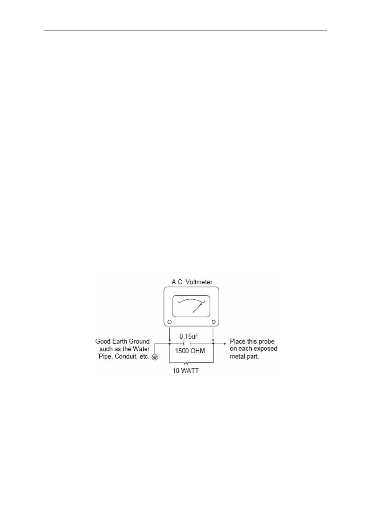
6. After reassembly of the set, always perform an AC leakage test on all
exposed metallic parts of the cabinet (the channel selector knobs, antenna
terminals, handle and screws) to be sure that set is safe to operate without
danger of electrical shock. DO NOT USE A LINE ISOLATION
TRANSFORMER DURING THIS TEST. Use an AC voltmeter having 5000
ohms per volt or more sensitivity in the following manner:
a. Connect a 1500 ohm, 10 watt resistor, paralleled by a 0.15 µF 150V AC
type capacitor between a known good earth ground (water pipe, conduit,
etc.) and the exposed metallic parts, one at a time.
b. Measure the AC voltage across the combination of 1500 ohm resistor
and 0.15 µF capacitor.
c. Reverse the AC plug by using a non-polarized adaptor and repeat AC
voltage measurements for each exposed metallic part.
Voltage measured must not exceed 0.75 volts RMS. This corresponds to
0.5 milliamp AC. Any value exceeding this limit constitutes a potential
shock hazard and must be corrected immediately.
Implosion
All direct view picture tubes are equipped with an integral implosion protection
system; take care to avoid damage during installation. Use only the
recommended factory replacement tubes.
Dynex DX-19LD150A11/DX-22LD150A11 LCD TV/DVD combo service manual 5
Page 6
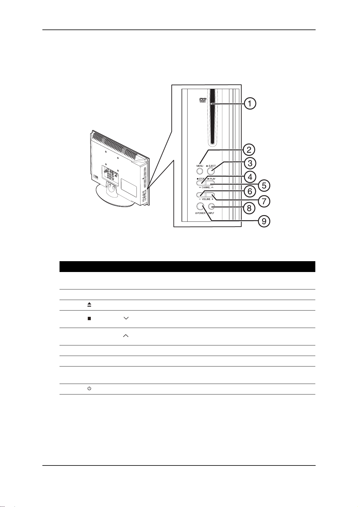
2. TV components
Side controls
#
1
2
3
4
5
6
7
8
9
Item Descriptions
Disc slot
MENU Press to open the on-screen TV menu.
EJECT button Press to eject the disc in the disc slot.
STOP / CH button
PLAY / CH button
VOL- Press to decrease the volume.
VOL+ Press to increase the volume.
INPUT
(Power) button Press to turn your TV/DVD combo on or off (standby mode).
Insert a disc (DVD or CD) into this slot to change mode and
begin playback.
In DVD mode, press to stop playback.
In TV mode, press to change channels.
In DVD mode, press to begin or resume playback.
In TV mode, press to change channels.
Press to select the AV signal input. You can select TV, A/V,
Component, DVD, HDMI1, HDMI2, VGA, or USB.
6 Dynex DX-19LD150A11/DX-22LD150A11 LCD TV/DVD combo service manual
Page 7
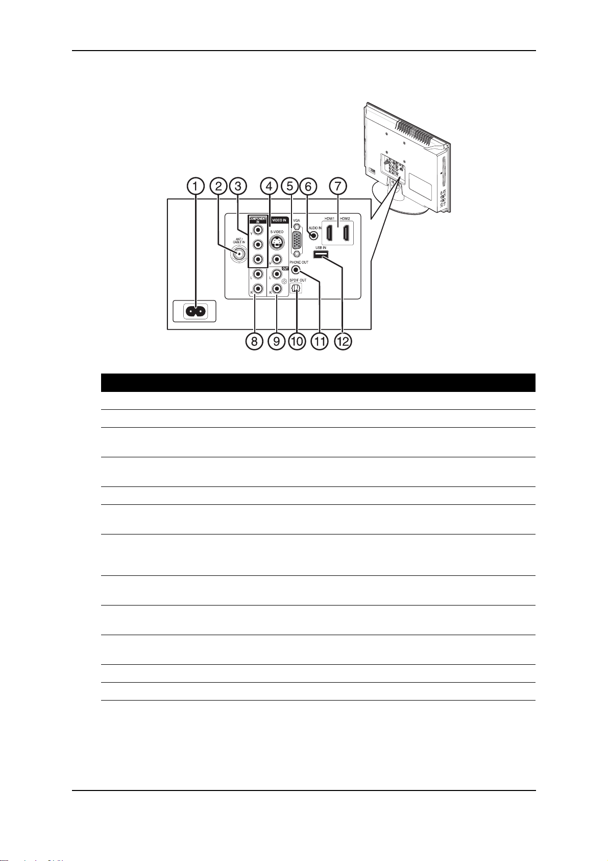
Back connectors
QD0EWJ
Q
C
Q
S
#
1
2
3
4
5
6
7
8
9
10
11
Item Descriptions
AC INPUT Connect the power cord to this jack.
ANT/CABLE IN jack Connect an antenna, cable TV, or a satellite box to this jack.
COMPONENT IN (Y, Pb,
r) jack
P
VIDEO IN (S-Video and
Video) jacks
Connect a component video device to these jacks.
Connect the video signal from an AV device to one of these
jacks.
VGA jack Connect the video signal from a computer to this jack.
PC/DVI AUDIO IN jack
Connect the audio signal from a computer or a DVI device to
this jack.
Connect an HDMI device, such as a cable box or DVD player,
HDMI1/HDMI2 jacks
COMPONENT/S-VIDEO/
AV IN (L/R Audio) jacks
AUDIO L/R OUT jacks
SPDIF OUT jack
to this jack. An HDMI cable carries both video and audio, so
you do not
need to make an audio connection.
Connect the audio signals from a component, S-Video, or
composite device to
these jacks.
Connect an analog sound system, such as an analog audio
amplifier, to these jacks.
Connect a digital sound system, such as a digital audio
amplifier, to this jack.
PHONE OUT jack Connect a headphone to this jack.
12
USB IN Plug a USB device, such as a flashdrive, into this jack.
Dynex DX-19LD150A11/DX-22LD150A11 LCD TV/DVD combo service manual 7
Page 8
3. Specifications
Item Description
Models DX-19LD150A11 / DX-22LD150A11
LCD Panel 19 or 22-inch active matrix full high definition
Resolution 1366 x 768
Color 6 bit with FRC/ 16.7 M
Viewing angle 170° horizontal - 160° vertical
Contrast ratio 1000:1
Brightness (typical) 250 nits
Response time 5.0 ms
TFT
Physical
specifications
TV Standard NTSC and ATSC
DX-19LD150A11 Dimensions (W × D × H)
With stand:
18.5 × 7.19 × 14.37 in
(470 × 182.5 × 365 mm)
Without stand:
18.5 × 2.87 × 12.74 in
(470 × 73 × 323.5 mm)
Weight
With stand: 9.48 lb (4.3 kg)
Without stand: 8.82 lb (4.0 kg)
DX-22LD150A11 Dimensions (W × D × H)
With stand:
21.18 × 7.24 × 15.63 in
(538 × 184 × 397 mm)
Without stand:
21.18 × 2.3 × 14.53 in
(538 × 71 × 369 mm)
Weight
With stand: 10.8 lb (4.9 kg)
Without stand: 10.14 lb (4.6 kg)
Tuning system Electronic tuning system
Frequency range VHF and UHF
CATV 135 channel, QAM channels
Compatibility 480i, 480p, 720p, 1080i
DVD player Disc compatibility 12 cm Digital Audio CD
CD-R
CD-RW
12 cm DVD-Video
DVD-R
DVD-RW
DVD+R
DVD+RW
DVD-R DL Dual Layer
DVD-RW Dual Layer
DVD+R Dual Layer
DVD+RW Dual Layer
8 Dynex DX-19LD150A11/DX-22LD150A11 LCD TV/DVD combo service manual
Page 9
Item Description
USB Compliance USB 2.0
Device compatibility USB flash drive
Power Input voltage DX-19LD150A11 - 120 VAC, 0.6 A
DX-22LD150A11 - 120 VAC, 0.88A
Consumption DX-19LD150A11 - <32.4 W
DX-22LD150A11 - <42.2 W
Off - <1 W
Speaker output 3W (two channels)
Terminals Standard AV Video, audio L/R
S-Video S-Video, audio L/R
Component Y, Pb, Pr audio L/R
HDMI 1 and 2 HDMI IN
VGA and VGA/DVI AUDIO INVGA and audio input
Phone jack Audio out (headphone)
Digital audio SPDIF output
Antenna F type
Image processor Broadcom Xilleon™ X143
Operating
conditions
Temperature 15°C to 40°C (humidity <75%)
Humidity 10% to 90% non-condensing
Atmospheric pressure 0 to 2000 m
(Ta <35%)
Dynex DX-19LD150A11/DX-22LD150A11 LCD TV/DVD combo service manual 9
Page 10
4. Calibration and adjustment
VGA ADC calibration
1. Turn on the TV/DVD combo.
2. Set the input source to VGA.
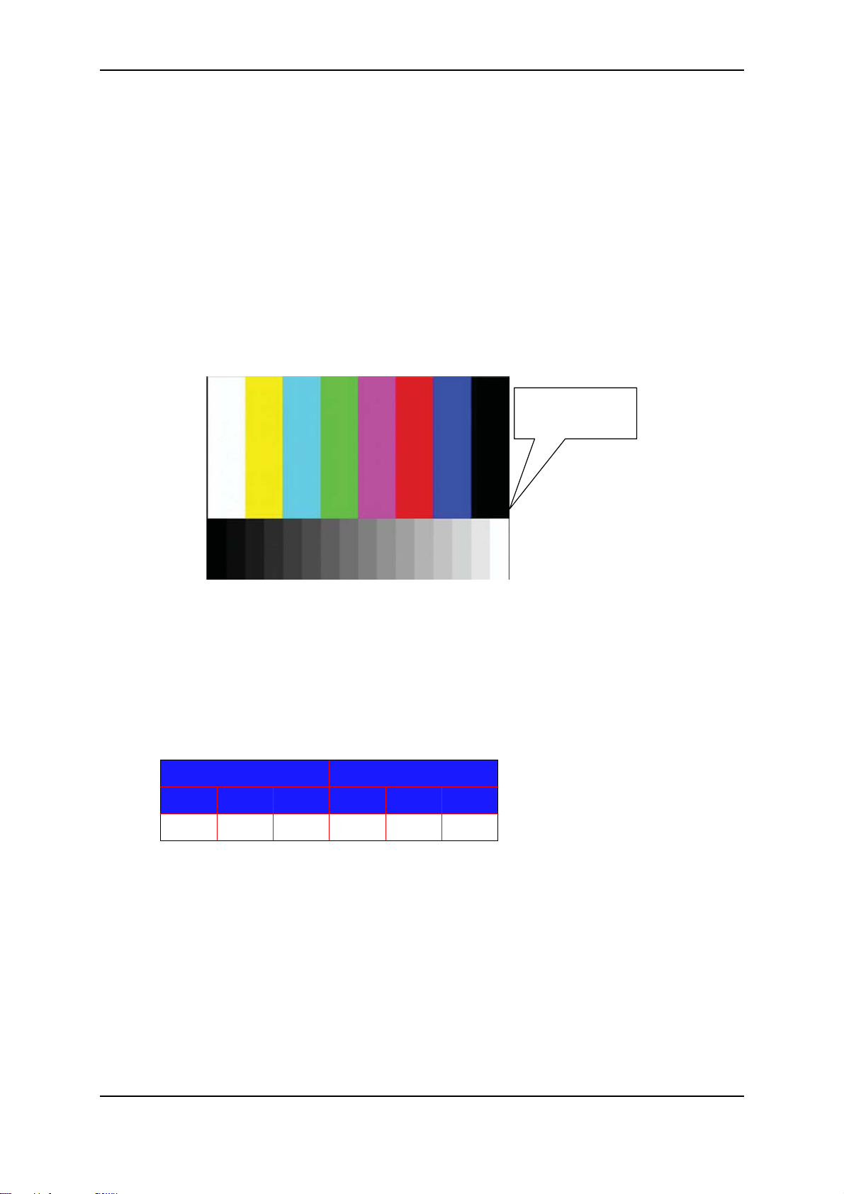
3. Select the calibration pattern.
• Set pattern “VGA timing 1024×768 / 60 Hz 48K” (VGA848 Timing856)
• 8 (100%) color bar + 16 (100%) grayscale, (pattern 918).
• Input level 100IRE 0.7Vp-p
The calibration picture
100% color bar
100% white bar
4. Press MENU + 1999 + ENTER on the remote control to enter factory mode.
5. Select “ADC Calibration” and then “Auto Calibration” in Factory Menu.
6. Press or ENTER to start calibration.
The ADC value is automatically adjusted. If there’s no change after adjustment,
check step 3 above and then perform the calibration again.
The default values are shown below.
VGA Offset VGA Gain
R G B R G B
16 10 16 4652 4636 4640
10 Dynex DX-19LD150A11/DX-22LD150A11 LCD TV/DVD combo service manual
Page 11
YPbPr ADC calibration
1. Turn on the TV/DVD combo.
2. Set the input source to Component.
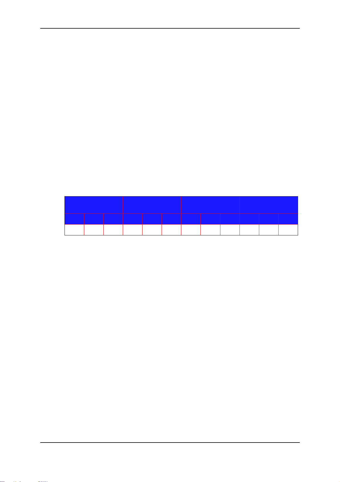
3. Select the calibration pattern.
• Set timing to 720P (Timing977)
• Set pattern to “8 color bar and 16 gray pattern” (Astro pattern 918).
• Input level 100IRE 0.7Vp-p
4. Press MENU + 1999 + ENTER on the remote control to enter factory mode.
5. Select “ADC Calibration” and then “Auto Calibration” in Factory Menu.
6. Press or ENTER to start calibration.
7. Check black pattern (0 IRE). The luminance should be under 1 cd/m2.
8. Repeat steps 3 to 7 for timing 480P (timing 978).
The ADC value is automatically adjusted. If there’s no change after adjustment,
check step 3 above and then perform the calibration again.
Component 480p
Offset
R G B R G B R G B R G B
1024 130 1024 3234 3262 3188 1024 130 1024 3070 3082 3031
Component 480p
Gain
Component 720p
Offset
Component 720p
Gain
Dynex DX-19LD150A11/DX-22LD150A11 LCD TV/DVD combo service manual 11
Page 12
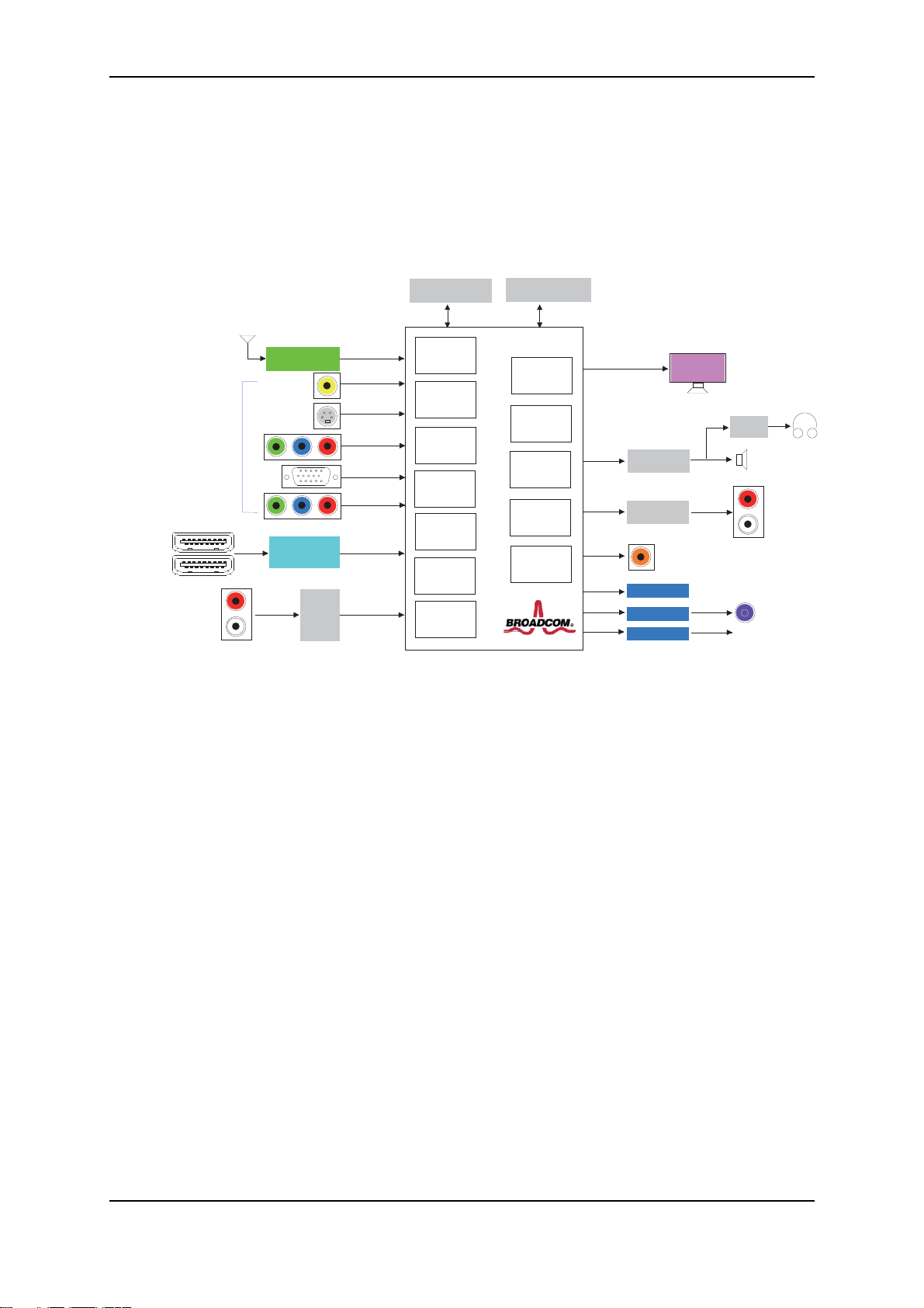
5. Block diagram
Line Driver
DRV602
Handphone
25mW/16 Ohm
I2S
R/L
HP AMP
TPA6132A2
LINE OUT
SCALER_UART
TVM_UART DVD Module
Factory_Debug
Winbond W9751G6IB-25
Winbond W25Q64BVSSIG
Broadcom
BCM35143
VSB/QAM
Demod
Signal MPEG
Video and
Audio
Decoder
WW Analog
Decoder
WW Analog
Decoder with
3D Comb
ADC VGA
656 Video
Capture
HDMI Rx
LVDS Tx
Video Display
Engine/Processing
Gamma LUT
Audio processing
and Audio DAC
MIPS CPU
ATSC Half NIM
NuTune FA2315
12 Analog Inputs
CVBS
S-Video
YPbPr
VGA
DVD_YPbPr
STA339BW
HDMI Processor
SiI9187A
HDMI*2
Audio
Switch
4052
Audio Inputs
CVBS, S-Video, Component
VGA
DVD_RL
DDR2, 32Mx16b Serial Flash, 64Mb
19" / 22"
1366*768
Single LVDS
Output
BCM35143
PWM
Speaker
3W/8Ohm *2
Audio AMP
SPDIF
USB 2.0
12 Dynex DX-19LD150A11/DX-22LD150A11 LCD TV/DVD combo service manual
Page 13
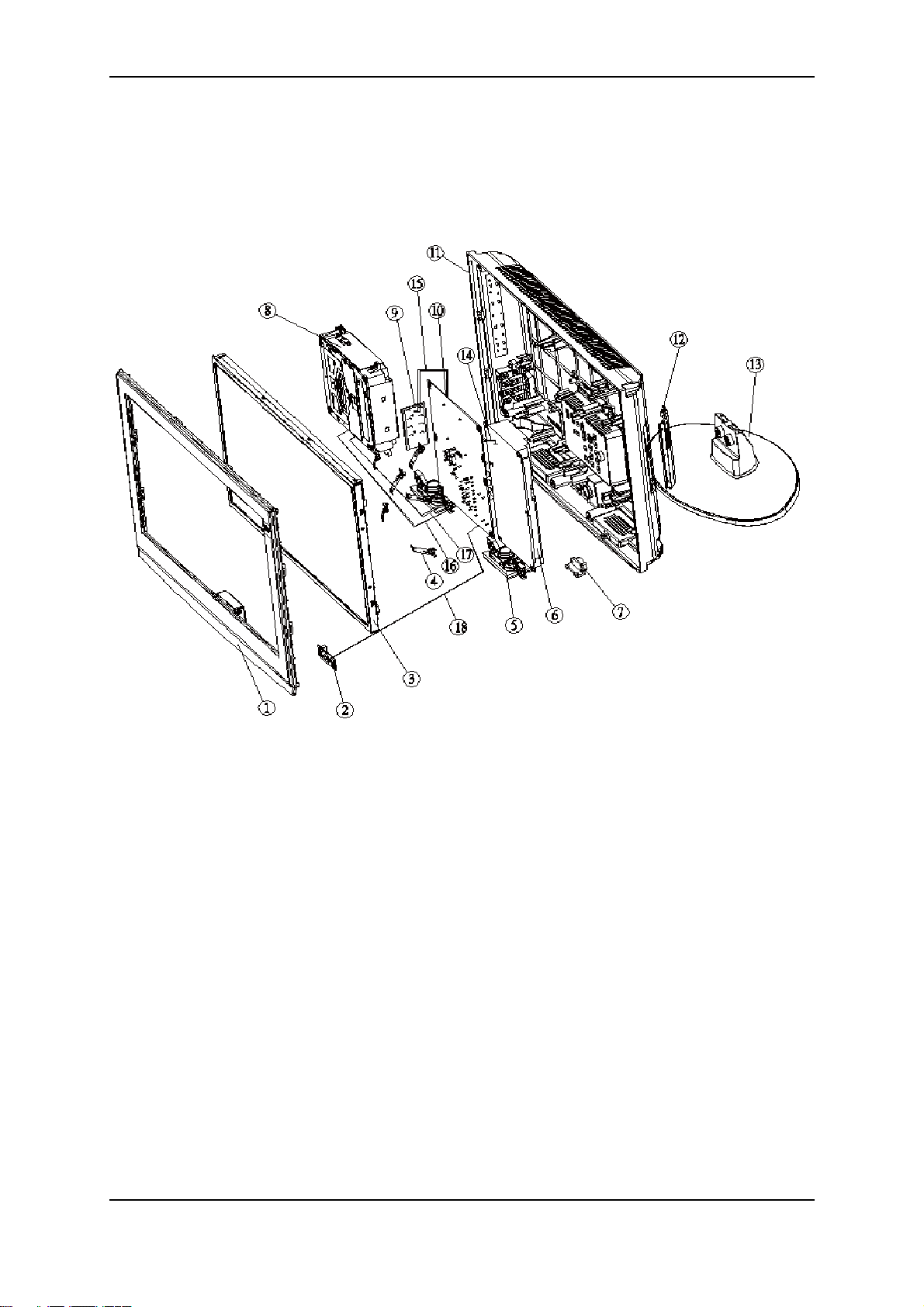
6. Exploded diagram
DX-19LD150A11
Dynex DX-19LD150A11/DX-22LD150A11 LCD TV/DVD combo service manual 13
Page 14
DX-19LD150A11
# Part Name Part Number
1 ASSY_FRONT-BEZEL-ANGUS-COMBO19 60.71V02.002
2 IR/LED ANGUS19_22 COMBO MP DIP 55.71V02.B01G
3 LCD 19" CMO M185B1-L02 56.07609.011
4 SPG-MB-G15 34.77A02.001
5 SPEAKER 8OHM 3W JONGGARXIN 001 23.42311.001
6 LIPS 53W DPS-53BP-1 A 00 ANGUS 56.04053.1C1
7 C.A.3-2P-AC-ANGUS-COMBO-19
8 DVD HH SL DESAY DS-C073-R 56.2338M.M02
9 KEYPAD BD ANGUS19_22 DD MP DIP 55.71V03.B01G
10 MB ANGUS19_22 COMBO X143 MP DI 55.71V01.B01G
11 ASSY_BACK-COVER-ANGUS-COMBO-19 60.71V04.002
12 CVR-INVERTER-ANGUS-COMBO-19 42.71V07.001
13 ASSY_STAND-FOOT-ANGUS-COMBO22 60.71V03.001
14 C.A.14-14P-POWER-ANGUS-19-DVD
15 C.A.3-3P-KEYPAD-ANGUS-19-DVD
16 C.A.9-9P-DVD-ANGUS-COMBO-19
17 C.A.12-12P-DVD-ANGUS-COMBO-19
18 C.A.5-5P-IR-LED-ANGUS-19-DVD
50.71V18.001
50.71V18.011
50.71V17.001
50.71V17.011
50.71V20.001
50.71V20.011
50.71V21.001
50.71V21.011
50.71V22.001
50.71V22.011
50.71V19.001
50.71V19.011
14 Dynex DX-19LD150A11/DX-22LD150A11 LCD TV/DVD combo service manual
Page 15
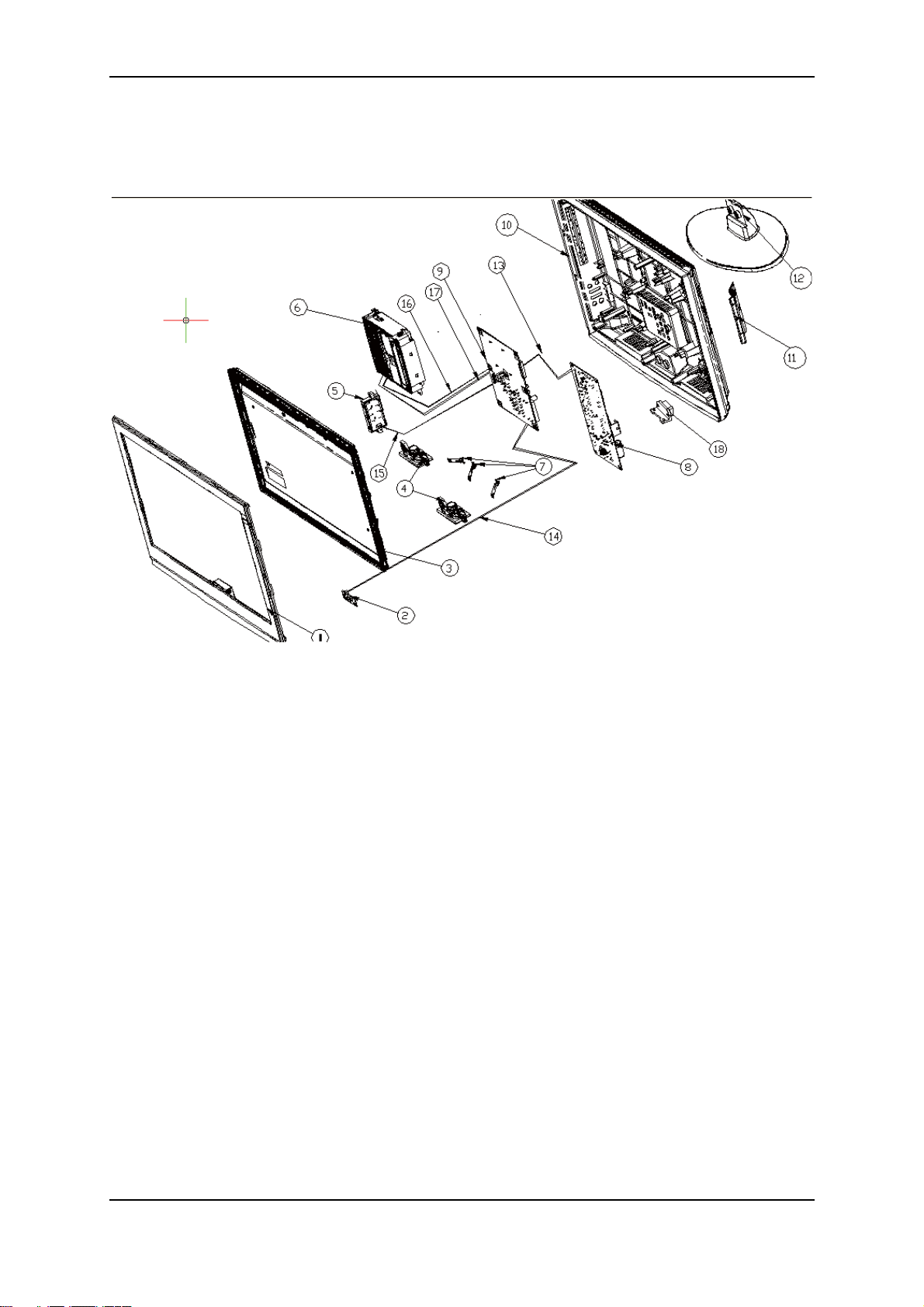
DX-22LD150A11
Dynex DX-19LD150A11/DX-22LD150A11 LCD TV/DVD combo service manual 15
Page 16
DX-22LD150A11
# Part Name Part Number
1 ASSY_BEZEL_FRONT_ANGUS22_COMBO 60.71V12.002
2 IR/LED ANGUS19_22 COMBO MP DIP 55.71V02.B01G
3 LCD 22" CMO V216B1-L03 56.07220.021
4 SPEAKER 8OHM 3W JONGGARXIN 001 23.42311.001
5 KEYPAD BD ANGUS19_22 DD MP DIP 55.71V03.B01G
6 DVD HH SL DESAY DS-C073-R 56.2338M.M02
7 SPG-MB-G15 34.77A02.001
8 LIPS DPS-65TP-2 A 00 ANGUS 22 56.04065.1H1
9 MB ANGUS19_22 COMBO X143 MP DI 55.71V01.B01G
10 ASSY_COVER_BACK_ANGUS22_COMBO 60.71V13.002
11 DOOR_LIPS_ANGUS22_COMBO 42.71V15.002
12 ASSY_STAND-FOOT-ANGUS-COMBO22 60.71V03.001
13 C.A.-POWER-14-14-ANGUS22
14 C.A.-IR-5-5-ANGUS22
15 C.A.-KEY-4-4-ANGUS22
16 C.A.-DVD-SIGNAL-12-12-ANGUS22
17 C.A.-DVD-PSU-9-9-ANGUS22
18 C.A.-AC-2-2-ANGUS22
50.71V14.001
50.71V14.011
50.71V15.001
50.71V15.011
50.71V16.001
50.71V16.011
50.71V24.001
50.71V24.011
50.71V25.001
50.71V25.011
50.71V26.001
50.71V26.011
16 Dynex DX-19LD150A11/DX-22LD150A11 LCD TV/DVD combo service manual
Page 17
7. Replacement parts list
DX-19LD150A11
# Part number Part name Descriptions
1 90.71V11.001 REMOTE CONTROL
2 91.71V10.B02G IR/LED BOARD
3 91.71V10.B01G KEYPAD BOARD
4 50.71V21.001 DVD CABLE 9/9PIN C.A.9-9P-DVD-ANGUS-COMBO-19
5 50.71V22.002 DVD CABLE 12/12PIN C.A.12-12P-DVD-ANGUS-COMBO-19
6 50.71V23.001 LVDS CABLE 30/30PIN C.A.30-30P-FFC-ANGUS-COMBO-19
7 50.71V20.001
8 50.71V19.001 IR CABLE 5/5PIN C.A.5-5P-IR-LED-ANGUS-19-DVD
9 50.71V18.001 AC CABLE 3/2PIN C.A.3-2P-AC-ANGUS-COMBO-19
10 50.71V17.001 POWER CABLE 14/14PIN C.A.14-14P-POWER-ANGUS-19-DVD
11 27.01518.J11
12 42.71V07.001 INVERTER COVER CVR-INVERTER-ANGUS-COMBO-19
13 42.71V28.001 DVD SUPPORT COVER
KEYPAD BOARD CABLE 3/
3PIN
POWER CORD 125V BLACK
W/PLORIZED USA
REMOTE DONGIN T202-ANGUSCOMBO
IR/LED ANGUS19_22 COMBO MP
PAC
KEYPAD ANGUS19_22 DD MP
PACKIN
C.A.3-3P-KEYPAD-ANGUS-19-DVD
CORD 125V BLACK W/PLORIZED
USA
HLDR-SUPPORT-MCM8-ANGUS19DVD
14 60.71V04.002 BACK COVER 19"
15 60.71V02.002 FRONT BEZEL 19"
16 56.2338M.M02
17 6K.71VFT.001
18 56.07609.011 LCD 19" CMO M185B1-L02 LCD 19" CMO M185B1-L02
19 91.71V10.B03G
20 56.04053.1C1
21 23.42311.001
DVD-RW DRIVE DESAY
DS-C073-R
FOOT STAND PACK W/
SCREW
MAINBOARD ANGUS19_22
COMBO X143
POWER SUPPLY 53W
DPS-53BP-1
SPEAKER 8OHM 3W
JONGGARXIN
ASSY_BACK-COVER-ANGUSCOMBO-19
ASSY_FRONT-BEZEL-ANGUSCOMBO19
DVD HH SL DESAY DS-C073-R
STAND BASE PACK W/SCREW
MB ANGUS19_22 COMBO X143 MP
LIPS 53W DPS-53BP-1 A 00 ANGUS
SPEAKER 8OHM 3W JONGGARXIN
001
Dynex DX-19LD150A11/DX-22LD150A11 LCD TV/DVD combo service manual 17
Page 18
DX-22LD150A11
# Part number Part name Descriptions
1 90.71V11.001 REMOTE CONTROL
2 91.71V10.B01G KEYPAD BOARD
3 91.71V10.B02G IR/LED BOARD IR/LED ANGUS19_22 COMBO MP PAC
4 50.71V15.001 IR CABLE 5/5PIN C.A.-IR-5-5-ANGUS22
5 50.71V14.001 POWER CABLE 14/14PIN C.A.-POWER-14-14-ANGUS22
6 50.71V25.002 DVD CABLE 9/9PIN C.A.-DVD-PSU-9-9-ANGUS22
7 50.71V24.001 DVD CABLE 12/12PIN C.A.-DVD-SIGNAL-12-12-ANGUS22
8 50.71V26.001 AC CABLE 2/2PIN C.A.-AC-2-2-ANGUS22
9 50.71V27.011 LVDS CABLE 30/30PIN C.A.30-30P-FFC-CMO-ANGUS22
10 50.71V16.001
11 27.01518.J11
12 42.71V15.001 LIPS COVER DOOR_LIPS_ANGUS22_COMBO
13 60.71V12.002 FRONT BEZEL 22"
14 60.71V13.002 BACK COVER 22"
KEYPAD BOARD CABLE 4/
4PIN
POWER CORD 125V BLACK
W/PLORIZED USA
REMOTE DONGIN T202-ANGUSCOMBO
KEYPAD ANGUS19_22 DD MP
PACKIN
C.A.-KEY-4-4-ANGUS22
CORD 125V BLACK W/PLORIZED USA
ASSY_BEZEL_FRONT_ANGUS22_
COMBO
ASSY_COVER_BACK_ANGUS22_
COMBO
15 56.2338M.M02
16 6K.71VFT.001
17 56.07220.021 LCD 22" CMO V216B1-L03 LCD 22" CMO V216B1-L03
18 91.71V10.B03G
19 56.04065.1H1
20 23.42311.001
DVD-RW DRIVE DESAY
DS-C073-R
STAND BASE PACK W/
SCREW
MAINBOARD ANGUS19_22
COMBO X143
POWER SUPPLY DEL T A LIPS
DPS-65TP-2
SPEAKER 8OHM 3W
JONGGARXIN
DVD HH SL DESAY DS-C073-R
STAND BASE PACK W/SCREW
MB ANGUS19_22 COMBO X143 MP
LIPS DPS-65TP-2 A 00 ANGUS 2
SPEAKER 8OHM 3W JONGGARXIN
001
18 Dynex DX-19LD150A11/DX-22LD150A11 LCD TV/DVD combo service manual
Page 19
8. System disassembly procedure
Disassembly reminders
• ESD precautions should be observed to prevent damaging the internal
components.
• Follow the sequence indicated in the illustrative figures when removing the
screws securing the components.
• The screws for the different components vary in size. During the disassembly
process, group the screws with their corresponding components to avoid
mismatches when putting back the components.
• Prior to disassembly, place the TV on a stable, level surface protected by a
cushion.
Disassembly procedures
DX-19LD150A11
1. Disconnect the AC power cord from the TV.
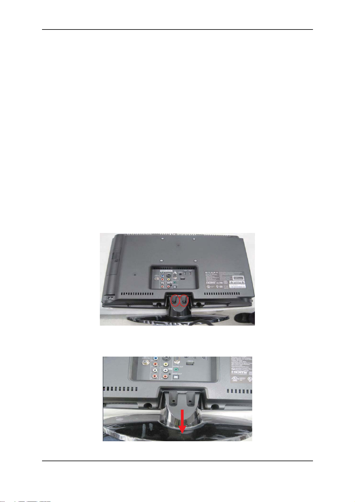
2. Remove the 2 screws securing the pedestal stand.
M4*L18 screw—86.1H256.180
3. Remove the pedestal stand.
Pedestal stand—60.71V03.001
Dynex DX-19LD150A11/DX-22LD150A11 LCD TV/DVD combo service manual 19
Page 20
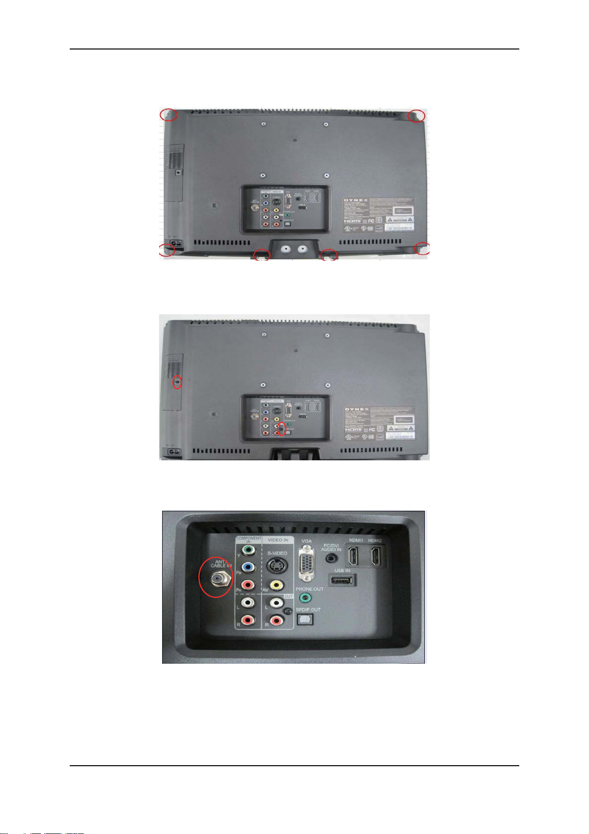
4. Remove the 6 screws securing the rear cover.
T4*L10 screw—86.EF256.100
5. Remove the 2 screws from the rear cover.
T3*L8 screw—86.CA214.8R0
6. Remove the tuner screw securing the rear cover.
Screw nut—87.1114C.C09
20 Dynex DX-19LD150A11/DX-22LD150A11 LCD TV/DVD combo service manual
Page 21
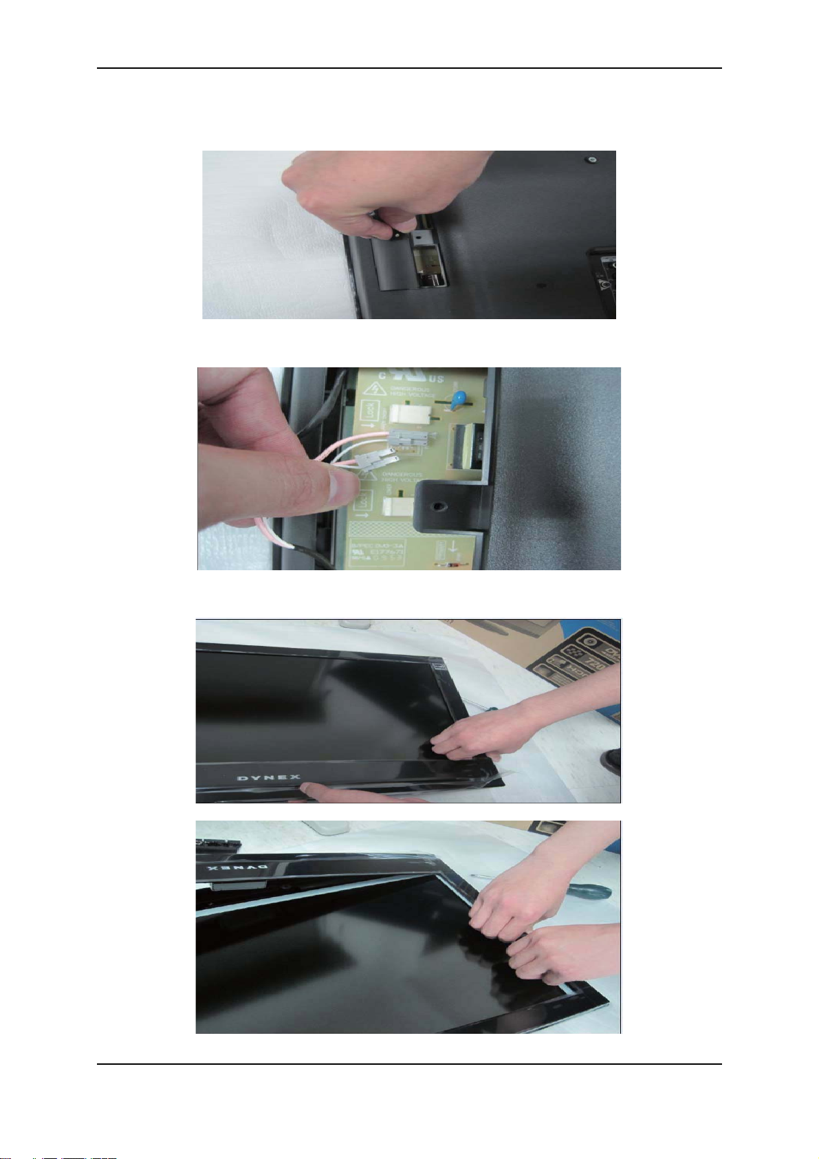
7. Remove the inverter cover from the rear cover.
Inverter cover—42.71V07.001
8. Disconnect the 2 panel lamp cable.
9. Turn the TV over and detach the front bezel from the rear cover.
Dynex DX-19LD150A11/DX-22LD150A11 LCD TV/DVD combo service manual 21
Page 22
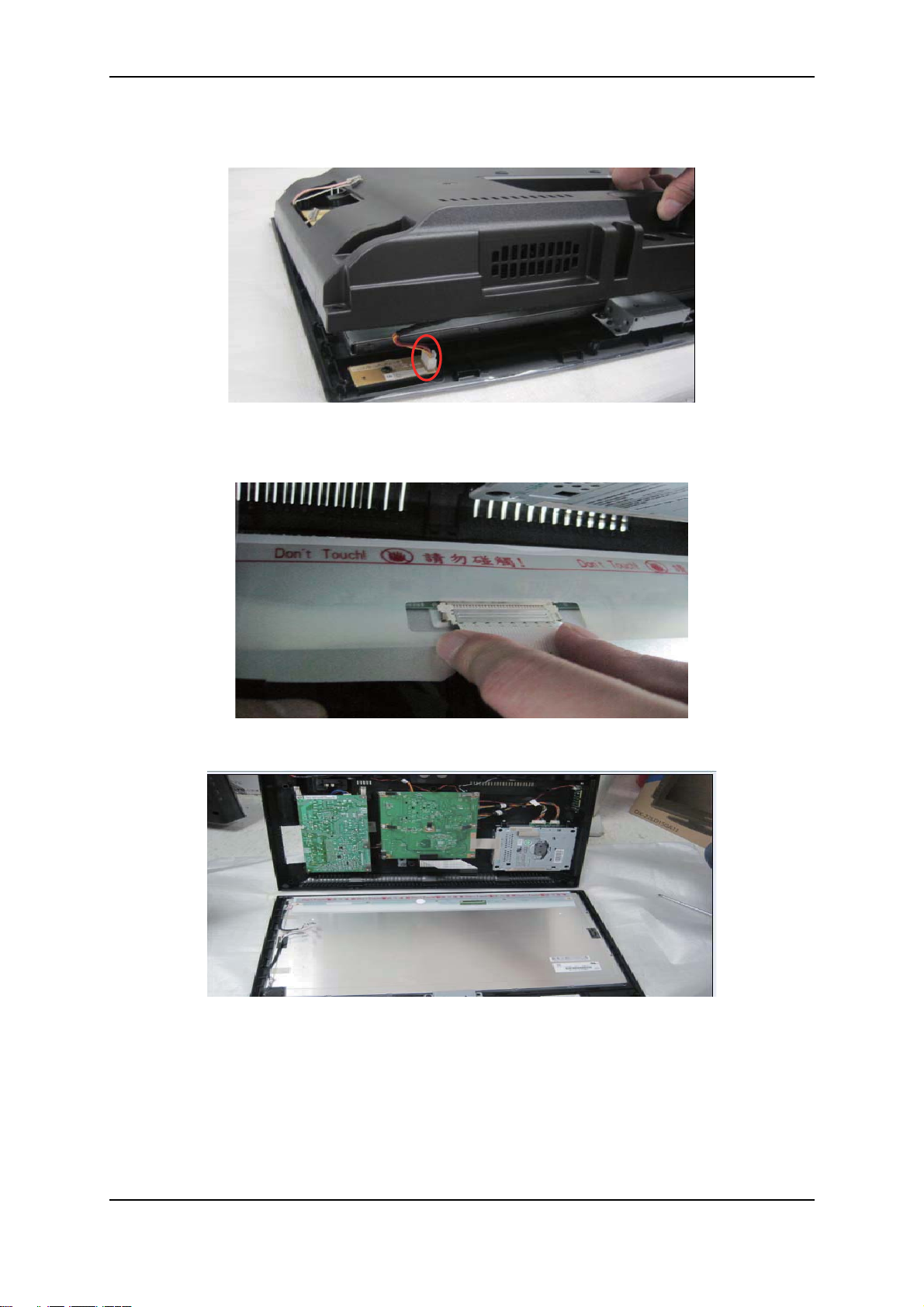
10.Turn the TV over back and disconnect the IR cable.
IR cable—50.71V19.001/50.71V19.011
11.Disconnect the LVDS cable from the panel.
LVDS cable—50.71V23.001/50.71V23.011
12.Separate the TV covers as shown below.
22 Dynex DX-19LD150A11/DX-22LD150A11 LCD TV/DVD combo service manual
Page 23
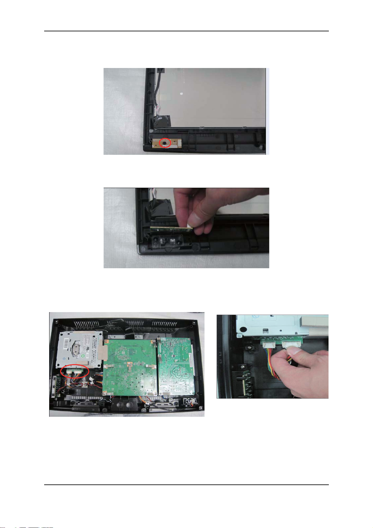
13.Remove the 1 screw on the IR/LED board.
Screw—86.CA214.8R0
14.Remove the IR/LED board.
IR/LED board—55.71V02.B01G
15.Disconnect the DVD signal and DVD power cable,
DVD signal cable—50.71V21.001/50.71V21.011
DVD power cable—50.71V22.001/50.71V22.011
Dynex DX-19LD150A11/DX-22LD150A11 LCD TV/DVD combo service manual 23
Page 24
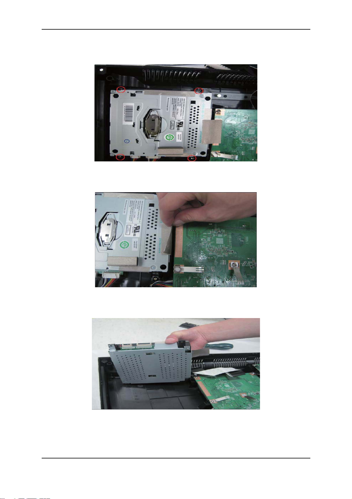
16.Remove the 4 screws securing the DVD module.
T3*L10 screw—86.YA524.100
17.Tear the tape off the main board.
Tape—42.3XC24.001
18.Remove the DVD module from the rear cover.
DVD module—56.2338M.M02
24 Dynex DX-19LD150A11/DX-22LD150A11 LCD TV/DVD combo service manual
Page 25
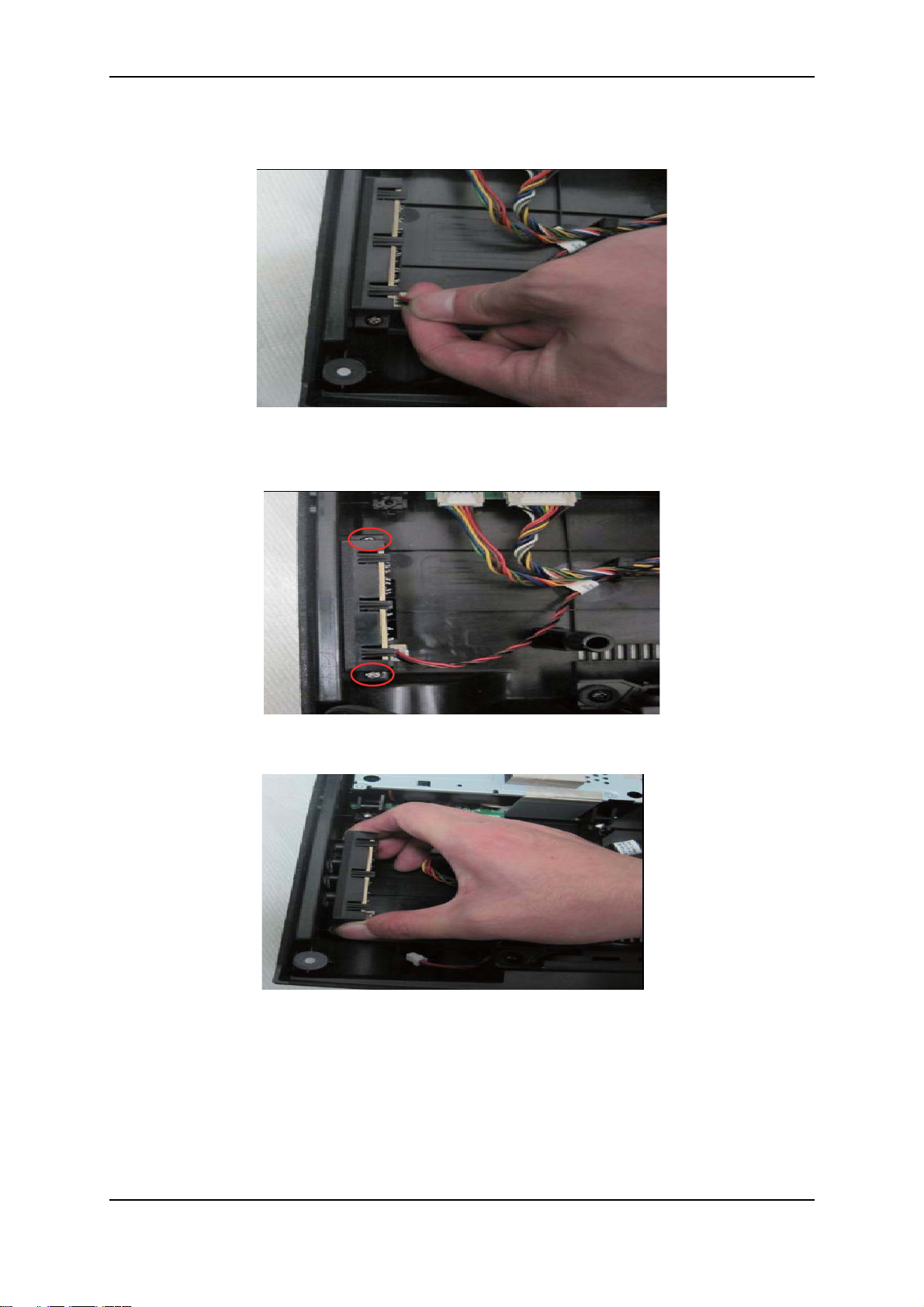
19.Disconnect the control cable from the control board.
Control cable—50.71V20.001/50.71V20.011
20.Remove the screws securing the control module.
T3*L10 screw—86.YA524.100
21.Remove the control module from the rear cover.
Dynex DX-19LD150A11/DX-22LD150A11 LCD TV/DVD combo service manual 25
Page 26

22.Remove the control board from the control module.
Control board—55.71V03.B01G
23.Remove the 5 screws securing the main board.
T3*L10 screw—86.YA524.100
24.Disconnect the power cable from the main board.
Power cable—50.71V17.001/50.71V17.011
26 Dynex DX-19LD150A11/DX-22LD150A11 LCD TV/DVD combo service manual
Page 27

25.Turn over the main board and disconnect the rest of the cables.
Cables—50.71V21.001/50.71V21.011
50.71V22.001/50.71V22.011
50.71V23.001/50.71V23.011
26.Remove the 2 supports on the edge of the main board.
Support—42.71V28.001
27.Remove the 6 springs from the main board.
Spring—34.77A02.001
Dynex DX-19LD150A11/DX-22LD150A11 LCD TV/DVD combo service manual 27
Page 28

28.Disconnect the speaker cable from the main board.
29.Remove the main board from the rear cover.
Main board—55.71V01.B01G
30.Remove the 4 screws securing the speaker.
T4*L10—86.EF256.100
28 Dynex DX-19LD150A11/DX-22LD150A11 LCD TV/DVD combo service manual
Page 29

31.Remove the speaker from the rear cover.
Speaker—23.42311.001
32.Remove the 5 screws securing the power board.
T3*L10 screw—86.YA524.100
33.Remove the 3 springs from the power board.
Spring—34.77A02.001
Dynex DX-19LD150A11/DX-22LD150A11 LCD TV/DVD combo service manual 29
Page 30

34.Disconnect the power cable from the power board.
Power cable—50.71V17.001/50.71V17.011
35.Disconnect the AC cable from the power board.
AC cable—50.71V18.001/50.71V18.011
36.Remove the power board from the rear cover.
Power board—56.04053.1C1
30 Dynex DX-19LD150A11/DX-22LD150A11 LCD TV/DVD combo service manual
Page 31

DX-22LD150A11
1. Disconnect the AC power cord from the TV.
2. Remove the 2 screws securing the pedestal stand.
M4*L18 screw—86.1H256.180
3. Remove the pedestal stand from the TV.
Pedestal stand—60.71V03.001
4. Remove the 8 screws securing the rear cover.
T3*L8 screw—86.CA214.8R0
Dynex DX-19LD150A11/DX-22LD150A11 LCD TV/DVD combo service manual 31
Page 32

5. Remove the tuner screw securing the rear cover.
Screw nut—87.1114C.C09
6. Remove the LIPS door from the rear cover.
LIPS door—42.71V15.002
7. Disconnect the 4 panel lamp cables.
32 Dynex DX-19LD150A11/DX-22LD150A11 LCD TV/DVD combo service manual
Page 33

8. Turn the TV over and detach the front bezel from the rear cover.
9. Turn the TV over back and disconnect the IR cable.
IR cable—50.71V15.001/50.71V15.011
Dynex DX-19LD150A11/DX-22LD150A11 LCD TV/DVD combo service manual 33
Page 34

10.Disconnect the LVDS cable from the panel.
LVDS cable—50.71V27.001/50.71V27.011
11.Separate the TV covers as shown below.
12.Remove the 1 screw on the IR/LED board
Screw—86.CA214.8R0
34 Dynex DX-19LD150A11/DX-22LD150A11 LCD TV/DVD combo service manual
Page 35

13.Remove IR/LED board.
IR/LED board—55.71V02.B01G
14.Disconnect the DVD signal and DVD power cables.
DVD signal cable—50.71V24.001/50.71V24.011
DVD power cable—50.71V24.001/50.71V24.011
15.Remove the 4 screws securing the DVD module.
T3*L10 screw—86.YA524.100
Dynex DX-19LD150A11/DX-22LD150A11 LCD TV/DVD combo service manual 35
Page 36

16.Tear the tape off the main board.
Tape—42.3XC24.001
17.Remove the DVD module from the rear cover.
DVD module—56.2338M.M02
18.Disconnect the control cable from the control board.
Control cable—50.71V16.001/50.71V16.011
36 Dynex DX-19LD150A11/DX-22LD150A11 LCD TV/DVD combo service manual
Page 37

19.Remove the screws securing the control module.
T3*L10 screw—86.YA524.100
20.Remove the control module from the rear cover.
21.Remove the control board from the control module.
Control board—55.71V03.B01G
Dynex DX-19LD150A11/DX-22LD150A11 LCD TV/DVD combo service manual 37
Page 38

22.Remove the 5 screws securing the main board.
T3*L10 screw—86.YA524.100
23.Disconnect the power cable from the main board.
Power cable—50.71V14.001/50.71V14.011
24.Turn over the main board and disconnect the rest of the cables
Cables—50.71V24.001/50.71V24.011
50.71V25.001/50.71V25.011
50.71V27.001/50.71V27.011
38 Dynex DX-19LD150A11/DX-22LD150A11 LCD TV/DVD combo service manual
Page 39

25.Remove the 2 supports on the edge of the main board.
Support —42.71X30.001
26.Remove the 6 springs from the main board.
Spring—34.77A02.001
27.Disconnect the speaker cable from the main board.
Dynex DX-19LD150A11/DX-22LD150A11 LCD TV/DVD combo service manual 39
Page 40

28.Remove the main board from the rear cover.
Main board—55.71V01.B01G
29.Remove the 4 screws securing the speaker.
T4*L10—86.EF256.100
30.Remove the speaker from the rear cover.
Speaker—23.42311.001
40 Dynex DX-19LD150A11/DX-22LD150A11 LCD TV/DVD combo service manual
Page 41

31.Remove the 5 screws securing the power board.
T3*L10 screw—86.YA524.100
32.Remove the 4 springs from the power board.
Spring—34.77A02.001
Dynex DX-19LD150A11/DX-22LD150A11 LCD TV/DVD combo service manual 41
Page 42

33.Disconnect the power cable from the power board.
Power cable—50.71V14.001/50.71V14.011
34.Disconnect the AC cable from the power board.
AC cable—50.71V26.001/50.71V26.011
35.Remove the power board from the rear cover.
Power board—56.04065.1H1
42 Dynex DX-19LD150A11/DX-22LD150A11 LCD TV/DVD combo service manual
Page 43

9. Power schematic diagram
IR/LED
0.007A
0.02A
SiI9287A
IC701
5V_SB/0.0201A
5V_SB/0.02A
5V_SB/0.007A
5V_VCC/0.5A
5V_VCC/0.85A
PSU_5V_SB/0.494A
12V/0.155A
5V/0.85A
5V/0.5A
12V/0.8A
12V/0.8ADVD
APW7120KE
IC201 5V_VCC/2.883A
TPA6132
U20
5V_VCC/0.011A
5V/0.011A
PSU_12V/1.51A
PSU_12V/1.5A
IC501
BCM35143IC4401
DDR2-800,512Mhz.
IC204
APL5312-33B
120uA
APL5312-18B
IC203
IC202
135uA
APL5315-ADJ
1V/0.02A
3.3V/0.005A
1.8V/0.747A
1.8V/0.016A
1V/1.775A
1.8V/0.5A
3.3V/0.117A
IC208 1V/1.65A
5V_VCC/0.61A
G966A
5V_SB/0.0101A
5V_SB/0.42A
5V_VCC/0.793A
IC205 3.3V/0.793A
5V_SB/0.0161A
1.8V/1.342A
APW7145
APW7142
IC207
AON_VDD18
AON_VDDR3
VDD1 8
VDDR 3
AON_VDDC
VDDC
CN50 1 5V/0.85A
PANEL T- CONAPM2301
Q501
TUNER
U19 5V/0.155A
12V/0.155A
4052
IC801 12V/??A
USB2 .0
STK2 5V/0.5A
APM2301
Q951
IC802 12V/0.5A
AMP 8ohmx3Wx2
12V/0.5A
IC701
3.3V/0.05A
3.3V/0.03AIC843
SiI9185A
DRV602
3.3V/0.2A
SiI9185A
1.8V/0.27A
IC701
PA102F
Q205
5V/0.155A
AP1117
IC206
120uA
Dynex DX-19LD150A11/DX-22LD150A11 LCD TV/DVD combo service manual 43
Page 44

10. System board layout
M333
D563:
D381
D918
M923
S944
M917
S24:
D96:
S248
S934
D266
D926
D929
D945
M916
M922
V26
S247
E815
E817
E816
S88:
S881
D849
D83:
S827
S891
S323
D328
M317
D325
S5559
D333
D334
JD5514
S5555
R5515
E5513
S5563
S556:
S5721
D5761
R5514
R5516
R5518
S5564
R5517
JD5513
I5
D933
DO413
S93:
D364
D971
D633
DO5517
DO5518
S252
S251
D244
D243
D236
D284
D283
S5573
S5572
D968
D967
D235
D234
D22:
S319
S329
S32:
M316
S22
D332
JD315
E747
M339
S554:
I6
I21
S328
D731
M318
V2:
D347
I4
D931
S949S94:
R917
S943
S946
D937
M329
JD317
D336
M323
S938S941
S939
E748
R916
S951
S5574
D372 D36:
D367
S362
D373
D837
M328
M327
S82
DO313
D379
S448
D841
S363
D374
I2
TX4
TX3
TX2
S335
S337
S338
D349
R317
S334
R316
E912
S942
S947
S948
S343
S983
JD318
R918
S364
S344
D371
M314
D318
D317
R312
I3
S828
D345
S331
D335
D311 R318
S342
S345
D343
S341
D351
S33:
D346
D342
M324
D368
D313
E312
D314
S313
D324
S316
D354
S829
D361
M322
D344
D348
D34:
M5527
M5528
JD312
D312
S31:
M315
KL4
D619
D615
S327
S326
S325
D331
R315
R314
S324
E313
D323
S312
S314
S321
S318
S315
S317
S348
D358
D355
M326
R313
D31:
D321
JD319
M32:
S353
S354
DO412
D322
D35:
S352
S351
D359
DO747
E314
I8
S612
S615
D356
M325
S346
D353
E767
D352
S5579
S5581
D521:
R5521
D613
D5554
I:
D357
D363
S347
S726
S727
S728S729
D723
D725
D726
D727
E719
E71:
S5578
D5219
S557:
R551:
S5524
S5525
S5521
S5522
D5582
D5629
JD612
S617
S616
S618
S619
I22
Y5512
S5523
D55::
D562:
M5534
S624
S623
S622
S621
S61:
TLU5
TLU4
D715
DO551:
S714
D5611
S5538
D55:9
M5526
D5631
JD512
S625
DO612
S71:
S723
D721
D722
D912
S752
D712
D714
S72:
S731
D724
D728
S753
WS4
D952
D956
S971
S977
WS5
D953 G:62
R922
S355
D758
E749
E715
D716
S713
E712
D719
D71:
D818
D824
D821
M819
M821
D5561
D5565
D5564
M5512
M5522
S5537
D55:1
D5626
M5532
D5625
M912
D913
S912
S91:
S981
S97:
S979
S978
S922
R912
S982
D944
M921
R925
D341
D5637
S5587
D631
V31
S5584
S5586
M331
TLU6
D:62
JD743
S336
S339
D713
KL3
D717
S712
E716
D718
D819
D825
S716
M816
M818
M822
D81:
D822
D826
M817
M81:
M823
D5653
D5642
D5639
D5576
D5583
D5584
S5526
D5632
D5633
S492
S5566
S5567
S5568
D2117
D627
D5638
D625
S641
D626
M337
M612
S63:
D628
D629
R612
S913
S921
JD912
S72
S74
S97
S98
D969
D973
D976
D977
S5585
D2125
D2126
D2127
D2128
S:71
S:6:
D:63
S719
S876
D377
M827
M826
S717
D5652
D5578
D557:
UQ5518
S5561
S5565
S645
S643S664
D62:
D5634
S626
R324
S642
R614
R613
D942
S914
S915
S923
S924
D965
D943
S955
S71
S73
S:3
S:4
M914
M335
M91:
D957
D958
D919
S:69
S:68
D:67
D:66
DO812
D376
D375
M824
D5654
D5641
D5577
D5579
D5581
D5616
I7
D5617
S5547
D5552
S5542
S5545
S5546
S5528
S5575
S:34
UQ5512
UQ5517
S5562
UQ5514
UQ5515
UQ5516
D33:
M31:
I9
S359
S646
D339
M319
D338
M321
D964D966
D938D941
D939
D924
S953
JD913
S935
S936
D927
M924
UQ551:
S933
S973
R915
S5588
JD5515
E814
E813
E812
UQ5519
UQ5513
S838
S839
Y5513
S5558
S5557
S322
S843
S842
S5548
S5551
S5722
S5725
D5636
S:33
S332
S333
D337
S5718
JD316
DO915
D962
D936
M332
M919
D932
M334
M918
S986
S99:
S9:2
D925
D928
M915
D5643
DO813
JD812
D326
D327
D329
D32:
JD313
JD314
D5618
S5556
S555:
S5723
D573:
R5553
JD5414
S5724
D5739
DO5514
S5571
R5519
D5619
DO5515
D95:
D963
D92:
D934
Top side
44 Dynex DX-19LD150A11/DX-22LD150A11 LCD TV/DVD combo service manual
Page 45

Bottom side
D817
D816S6S5
S82:
R8
S5597
S5594
R7
S5595
S815
S814
D812
D813
D823
D632
M812
D37:
S5596
S999
S998
S9:7
S9:8
D998
D365
R322
R31:
S:72
D5635
D382
S349
R319
D362
S34:
D99:
M954
S:13
S:16
D997
D9:2
D9:3
D9:4
D986
D988
S356
S366
M719
M721
E315
D989
JD954
D994
D5645
D5644
S467
S763
D748
D755
S766
D74:
D754
S767
WS6
S755
S769
D747
D757
S762
WS7
E732
D756
M71:
D752
E731
D753
E728
D9:1
R952
S952
S9:4
S:14
S:17
D987
D995
D999
D996
R415
R414
D5732
D5737
M5716
S9::
S9:9
S9:6
S:15
S76:
S772
D614
D624
D612
D616
D617
D61:
D621
S468
E762
E75:
D5717
E768
D5718
M5713
D5733
D5738
M5717
S771
S613
S614
D618
D622
D623
D745
M717
S5582
E758
E766
S5513
R5513
S754
D959
D729
E713
E717
S718
S721
S5512
D5522
D55:8
M5525
D5523
D5551
R5512
D5517
D5531
D5538
D555:
D55:2
M5521
D5518
D5525
D5555
D5557
D551:
D5556
D5558
D5559
D5516
D5587
R924
S841
S83:
S724
S725
S357
S846
D72:
M712
S715
S722
S5713
S5717
S5716
D556:
D5571
D5598
D5599
D55:7
M5513
M551:
D5566
D5515
D5528
D5512
D5592
D5593
D5524
D5595
D5596
M5517
M5519
WS3
WS2
D5562
D5563
D5575
M5514
M5515
D5567
D5568
D5574
D5572
S5519
S551:
D5573
D5513
D5514
D5533
D5537
D5534
D55:3
D55:4
M5524
D55:6
D5623
D5588
D5622
S246
S245
S244
D561:
D5624
D559:
M5531
M5533
S5554D5612
D5613
D5569
D5526
D552:
D5543
D5542
D5545
D5594
D55:5
M5523
D5532
D5621
D5536
D5589
D5628
D5627
D843
D831
D848
D844
D5614
D5615
M5529
M552:
S5583
S5541
S5576
D5546
S5527
D5519
D5527
D5544
D5521
D5585
D558:
D5597
M5518
D5529
D5535
D5586
D5591
M5516
D93:
:19D459S
S818
S816
D832
D833
D839
D369
D366
D846
S87:
D845
S5543
S5544
S358
S5539
S553:
S5553
E5512
D935 S945
D922
D961
D921
D923
D847
D838
D5548
D5549
D5547
D5647
S845
S847
S819
S817
D5646
S243
S242
S241
D229
D228
D227
S9
S8
Dynex DX-19LD150A11/DX-22LD150A11 LCD TV/DVD combo service manual 45
Page 46

11. Troubleshooting guide
Start
Is there screen
display?
Is the power
LED lit?
Is the TV connected
to an AC outlet?
Does the TV
function well?
System OK
Yes
Yes
Yes
Yes
Yes
Connect the TV
to an AC outlet.
Press the power
button.
No
Did you press the
power button?
No
No
Yes
No power
No
Backlight failure
No
Check what the
problem is.
Video
Audio
Power
Problem diagnosis
46 Dynex DX-19LD150A11/DX-22LD150A11 LCD TV/DVD combo service manual
Page 47

Power-related troubleshooting
Power check
Is there a 5V_SB
power source?
No
Check if the power board
has 5V_SB source.
No
Power board is damaged.
Replace it with a new one.
Yes
Check if system board
MCU_3.3V is short to
GND.
No
L205 is damaged. Replace
the system board.
Yes
MCU is
damaged.
Replace the
system board.
Yes
Can you turn on the
system power?
Check if the system board
PS_ON# pin is set to low.
No
Power board is damaged.
Replace it with a new one.
Yes
Check if the Q206
base level is set to
high.
No
MCU is damaged. Replace
the system board.
Yes
No
Q206 is damaged.
Replace the
system board.
Yes
Is system power
from 12V PSU?
Check if the power board
has a 12V PSU source.
No
Power board is damaged.
Replace it with a new one.
Yes
Check if the IC1
drain has a 12V
PSU source.
No
System board is damaged.
Replace it with a new one.
Yes
No
LCD panel is
damaged.
Replace it with a
new one.
Yes
Is system power
from 5V PSU?
Check if the power board
has a 5V PSU source.
No
Power board is damaged.
Replace it with a new one.
No
System board is damaged.
Replace it with a new one.
Yes
Yes
Check if all power is
ready.
Yes
System OK
Turn on the TV.
Dynex DX-19LD150A11/DX-22LD150A11 LCD TV/DVD combo service manual 47
Page 48

Video-related problems
Video problem
Check if the input cable is
properly connected to the TV.
No OSD display or
video quality issue?
Quality issue
System board is damaged.
Replace it with a new one.
Press MENU to display the OSD.
No OSD display
Are you able to
display the OSD?
No
System board is damaged.
Replace it with a new one.
Yes
Which input source
has no OSD display?
VGA
TV
A/V
Component
HDMI
Check if the VGA
cable is connected
to the TV properly.
Check if the antenna
is connected to the
TV properly.
Check if the source
cable is connected to
the correct TV input
jacks.
Check if the source
cable is connected to
the correct TV input
jacks.
Check if the source
cable is connected to
the correct TV input
jacks.
Perform a channel
scan.
System board is
damaged. Replace it
with a new one.
System board is
damaged. Replace it
with a new one.
System board is
damaged. Replace it
with a new one.
System board is
damaged. Replace it
with a new one.
System board is
damaged. Replace it
with a new one.
No
No
No
No
No
48 Dynex DX-19LD150A11/DX-22LD150A11 LCD TV/DVD combo service manual
Page 49

Audio-related problems
Audio problem
Check if the input cable is
properly connected to the TV.
No audio output or
audio quality issue?
Is the Mute function
enabled?
No
Does the problem
happen to the TV
speakers only?
System board is damaged.
Replace it with a new one.
Quality issue
Yes
Is the internal speaker
cable connected to the
system board?
System board is damaged.
Replace it with a new one.
Yes
System board is damaged.
Replace it with a new one.
Yes
Yes
Press VOL+ to
enable the
sound.
No
Connect the
internal speaker
cable to the
system board
Dynex DX-19LD150A11/DX-22LD150A11 LCD TV/DVD combo service manual 49
Page 50

12. Factory reset
Input Source
Aging Mode
Internal Pattern
EDID WP
Site Air Channels
All Reset
Site Cable Channels
Power Status
Panel Selection
Color Temperature
ADC Calibration
Factory Reset
DVD Menu
Software Version
Model Name
Serial Number
AV table
Gamma
MCU Version
DVD Version
Factory Mode
[<][>] Set [ EXIT ] Exit
<[ TV ]>
<[ Off ]>
<[ Off ]>
<[ On ]>
<[ Off ]>
<[ Off ]>
<[ Off ]>
<[ Always Off ]>
<[ CMO 19 ]>
>>
>>
<[ On ]>
1.02.470
V19B43ACC
0001EJ0SA
CMO19.06.100624
CMO19.04.100624
0.24
C073-25
After the main board or panel is replaced, make sure to follow the below procedures to
perform factory reset.
1. Turn on the TV/DVD combo.
2. Press MENU + 1999 + ENTER on the remote control to enter factory mode.
3. If the panel is replaced, press
or to select Panel Selection, then press or
to select the panel type and press ENTER.
4. Press
or to select Factory Reset, then press or to select On and press
ENTER to start factory reset.
50 Dynex DX-19LD150A11/DX-22LD150A11 LCD TV/DVD combo service manual
5. Disconnect the AC power cord and then connect it back to restart the TV by
pressing button on the TV or on the remote control.
Page 51

Distributed by Xiamen Overseas Chinese Electronic Co.,LTD (XOCECO)
SERVICE MANUAL
Product Type: LCD TV
Chassis: KS Chassis
Manual Series:
Manual Part#: 9226KS7010
Model Line:
Product Year:
Product Safety Servicing Guidelines....................................................................................1
Remote Control Unit.............................................................................................................2
Main Unit (Front View/Side View/Rear View)........................................................................3
Specifications......................................................................................................................4
Alignment Instructions..........................................................................................................5
Software Upgrade Instructions...........................................................................................11
Working principle analysis of the unit................................................................................15
Block Diagram....................................................................................................................16
Troubleshooting Guides.....................................................................................................17
Wiring Diagram..................................................................................................................22
Schematic Diagram............................................................................................................23
Printed Circuit board layouts..............................................................................................28
Exploded View Parts List....................................................................................................30
CONTENTS
Page 52

Product Safety Servicing Guidelines
Temperature
Scope for operation
0 ~ +50 oC
Scope for storage -20 ~ +60 oC
Humidity Scope for operation 20% ~ 85%
Scope for storage 10% ~ 90%
ATTENTION: This service manual is only for service personnel to take
reference with. Before servicing please read the
following points carefully.
CAUTION: Do not attempt to modify this product in any way.
Ne v er pe r form cu sto m ize d insta l lat i ons wi thou t
manufacturer’s approval.
Unauthorized modifications will not only void the warranty,
but may lead to property damage or user injury.
Service work should be performed only after you are thoroughly
familiar with these safety checks and servicing guidelines.
GRAPHIC SYMBOLS
The exclamation point within an equilateral triangle
is intended to alert the service personnel to
important safety information in the service literature.
The lightning flash with arrowhead symbol within an
equilateral triangle is intended to alert the service
person ne l to the pre sence of noni ns ulated
“dangerous voltage” that may be of sufficient
magnitude to constitute a risk of electric shock.
6. Should there be smoke, abnormal smell or sound from the module,
please shut the power off at once. Likewise, if the screen is not
working after the power is on or in the course of operation, the
power must be cut off immediately and no more operation is allowed
under the same condition.
7. Do not pull out or plug in the connection wire when the module is in
operation or just after the power is off because in this case relatively
high voltage still remains in the capacitor of the driving circuit.
Please wait at least one minute before the pulling out or plugging in
the connection wire.
8. When operating or installing LCD please don't subject the LCD
components to bending, twisting or extrusion, collision lest mishap
should result.
9. As most of the circuitry in LCD TV set is composed of CMOS
integrated circuits, it's necessary to pay attention to anti statics.
Before servicing LCD TV make sure to take anti static measure and
ensure full grounding for all the parts that have to be grounded.
10.There are lots of connection wires between parts behind the LCD
screen. When servicing or moving the set please take care not to
touch or scratch them. Once they are damaged the screen would be
unable to work and no way to get it repaired.
If the connection wires, connections or components fixed by the
thermotropic glue need to disengage when service, please soak the
thermotropic glue into the alcohol and then pull them out in case of
damage.
11.Special care must be taken in transporting or handling it. Exquisite
shock vibration may lead to breakage of screen glass or damage to
driving circuit. Therefore it must be packed in a strong case before
the transportation or handling.
12.For the storage make sure to put it in a place where the environment
can be controlled so as to prevent the temperature and humidity
from exceeding the limits as specified in the manual. For prolonged
storage, it is necessary to house it in an anti-moisture bag and put
them altogether in one place. The ambient conditions are tabulated
as follows:
INSTRUCTIONS
Be sure to switch off the power supply before replacing or welding any
components or inserting/plugging in connection wire. Anti static
measures must be taken (throughout the entire production process!):
a) Do not touch here and there by hand at will;
b) Be sure to use anti static electric iron;
c) It's necessary for the welder to wear anti static gloves.
Please refer to the part list before replacing components that have
special safety requirements. Do not replace with different components
with different specs and type at will.
13. Display of a fixed p ict ure for a lo ng t ime may result in
app e a r a n ce o f p i c t u r e r e s i due o n t h e sc r e e n , a s
commonly call ed “g hos t shadow”. Th e ext ent of the
residual picture v ari es wi th th e maker of LCD screen.
LCD SERVICING PRECAUTIONS
1. Screens are different from one model to another and therefore not
interchangeable. Be sure to use the screen of the original model for
replacement.
2. The operation voltage of LCD screen is 700-825V. Be sure to take
proper measures in protecting yourself and the machine when
testing the system in the course of normal operation or right after
the power is switched off. Please do not touch the circuit or the
metal part of the module that is in operation mode. Relevant
operation is possible only one minute after the power is switched off.
3. Do not use any adapter that is not identical with the TV set.
Otherwise it will cause fire or damage to the set.
4. Never operate the set or do any installation work in bad environment
such as wet bathroom, laundry, kitchen, or nearby fire source,
heating equipment and devices or exposure to sunlight etc.
Otherwise bad effect will result.
5. If any foreign substance such as water, liquid, metal slices or other
matters happens to fall into the module, be sure to cut the power off
immediately and do not move anything on the module lest it should
cause fire or electric shock due to contact with the high voltage or
short circuit.
This phen ome non doe sn' t represent failure. This “ghost
shadow” may remain in the picture for a period of tim e
(several minutes). Bu t when operating it p lea se avoid
displaying still picture in high brightness for a long time.
Points for attention during installation
1. The fron t pan el of LCD s cre en is of glass. When
installing it please make sure to put it in place.
2. For service or ins tal lat ion it' s ne ces sar y to use
specified screw lest it should damage the screen.
3. Be sure to take anti dust measures. Any foreign
substance that happen s to fa ll do wn between the screen
and the glass will affec t the r ece ivi ng an d vie win g effec t
4. W hen dismantling o r mounting the pr ote cti ve partition
plate t hat is used f or anti vib rat ion and insulation ple ase
take care to keep it in intac tne ss so as to avo id hi dde n
trouble.
5. Be su re to protect the cabinet from dam age o r scratch
during service, dismantling or mounting.
1
Page 53

Remote control
Remote Control Unit
10
INPUT POWER
2
1
4
2
5
3
6
3
7
8
0
9
RECALL
13
MENU
MUTE
VOL+/VOL–
VIDEO/HDMI/TV
COMP/VGA
Press to open the on-screen menu.
Press to turn off the sound. Press again to
turn on the sound.
Press to increase or decrease the volume.
Press to select the input source.
• Press VIDEO once to select AV1, twice to
select AV2, three times to select S-Video1,
and four times to select S-Video2.
• Press HDMI once to select HDMI1, twice
to select HDMI2, and three times to select
INFO
4
GUIDE
14
HDMI3.
! Press TV to select TV.
! Press COMP once to select Component1
or twice to select Component2.
! Press VGA to select VGA.
5
MENU
6
7
VOL+
8
VOL- CH
ENTER
MUTE
FAVOR IT E
EXIT
CH
15
<
16
<
10
11
12
SLEEP
ZOOM
PICTURE
Press to set the sleep timer.
Press to select the aspect ratio.
Press to select the picture mode.
17
11
VIDEO
9
COMP
ZOO M
HDMI
MTS/SAP
SLEEP
TV
VGA
CH-LIST
18
19
13
14
RECALL
GUIDE
Press to go to the last viewed channel.
Press to open the DTV program guide (if
available).
12
PICTURE
INPUT
Numbers/Dot(.)
INFO
AUDIO
CCD
20
21
Press to turn on your TV. Press again to put
your TV in Standby mode.
Press to open the INPUT SOURCE menu,
then press 5 or 6 to select the video input
source.
Press to enter channel numbers or the
parental control password. Press the dot
button to select a digital sub-channel.
Press to display the information banner.
Press direction buttons to navigate in the onscreen menus. Press ENTER to confirm
selections in an on-screen menu or to open a
submenu.
15
16
17
18
19
20
21
EXIT
<
CH /CH
FAVORITE
MTS/SAP
CH-LIST
CCD
AUDIO
<
Press to close the on-screen menu.
Press to go to the next or previous channel in
the channel list.
Press to display the favorite channel list.
Press to select the audio mode. For analog
channels, you can select STEREO, SAP
(secondary audio program), or MONO. For
digital channels, you can select the audio
track (if more than one track is available).
Press to open the channel list.
Press to turn closed captioning on or off.
Press to select the sound mode.
2
Page 54

Main Unit (Front View/Side View/Rear View)
SERVI CE PORT
HDMI 2
R
AUDIO
L
AV2 IN
VIDEO
<
<
DIGITAL OUTPUT
1
jack
2
HDMI1 jack
PC IN VGA/AUDIO jacks
3
4
S-VIDEO/AV1 IN
jack
B R
PC IN
VGA
Connect this jack to a digital sound system to
play your TV’s audio through the sound system.
For more information, see “Connecting a digital
sound system” on page 10.
Connect an HDMI device, such as a cable box or
DVD player, to the jack. An HDMI cable carries
both video and audio, so you do not need to
mak e an audio connection. For more
information, see “Connecting an HDMI device”
on page 9.
Connect a computer to these jacks. For more
information, see “Connecting a computer” on page 10.
Connect an AV or S-Video device to these jacks,
then connect audio cables to the audio jacks.
ANT/ CA BLE IN
<
5
AUDIO OUT jack
6
COMPONENT IN
jacks
7
ANT/CABLE IN
jack
8
AV2 IN jack
<
-
+
9
HDMI2 jack
10
Headphone jack
11
SERVICE PORT
Connect an audio amplifier to these jacks.
Connect a component video device to these jacks.
For more information, see “ Connecting a
component video device” on page 9.
Connect an antenna, cable TV, or a satellite box to
this jack. For more information, see “Connecting an
antenna, cable TV, or satellite TV box” on page 8.
Connect an AV device (video and audio) to these
jacks. Match the color of the connectors to the
color of the jacks (yellow for video, red for audio
right, and white for audio left).
Connect an HDMI device, such as a cable box or
DVD player, to this jack.
Plug headphones into this jack.
For software update only. Do not use.
3
Page 55

SPECIFICATIONS
26” TF T LCD
NTSC-M, ATSC
VHF: 2-13
UHF: 14-69
CATV: 1-125
CADTV: 1-135
DTV: 2-69
5 W x 2
85 W
646 x 462 x 256 mm (Stand included)
8.2 kg (Stand included)
Audi o left an d right ( 1)
Digi tal out put (1)
Head phone j ack (1)
Note:
1. Design and specifications are subject to change without notice.
2. Weight and dimensions shown are approximate.
3. Specifications and external appearance may be changed for the sake of improvement.
4
Page 56

ALIGNMENT INSTRUCTIONS
1. Test equipment
VG848 (YPbPr, VGA signal generator)
VG849 (HDMI signal generator)
CA210 (color analyzer)
2. Alignment procedure
2.1 Connect all the boards according to wiring diagram. Connect the power supply and
presss “standby” to turn on the TV.
2.1.1 For 32” /37” /42”/46” model
a) In turn measure X508 all pins voltage on Power Board, the value is shown below (Table 1):
Table 1 X508 all pin voltage
Pin 1 2 3 4, 5 6, 7 8 9 10 11 12 13
Min.(V) 4.85 3.25 0 11.3 0 0 4.85 0 4.85 0 2.85
Typical(V) 5.00 3.30 0 12.0 0 0 5.00 0 5.00 0 3.00
Max.(V) 5.35 3.30 0 12.6 0 0 5.35 0 5.35 0 3.15
b) In turn measure X505 all pins voltage on Power Board, the value is shown below (Table 2):
Table 2 X505 all pin voltage
Pin 1, 2 3, 4, 5
Min.(V) 23.8 0
Typical(V) 24.0 0
Max.(V) 25.2 0
c) In turn measure X503 all pins voltage on Power Board, the value is shown below (Table 3):
Table 3 X503 all pin voltage
Pin 1~5 6~10 11 12
Min.(V) 23.8 0 3.25 4.85
Typical(V) 24.0 0 3.30 5.0
Max.(V) 25.2 0 3.30 5.35
2.1.2 For 26” model
a) In turn measure X505 all pins voltage on Power Board, the value is shown below (Table 4):
Table 4 X505 all pin voltage
Pin 1 2 3 4, 5 6, 7 8 9 10 11 12 13
Min. (V) 4.85 3.25 0 11.3 0 0 4.85 0 4.85 0 2.85
Typical(V) 5.00 3.30 0 12.0 0 0 5.00 0 5.00 0 3.00
Max. (V) 5.35 3.30 0 12.6 0 0 5.35 0 5.35 0 3.15
b) In turn measure X503 all pin voltage on the Power Board, the value is shown below (Table 5):
Table 5 X503 all pin voltage
Pin 1, 2 3, 4, 5
Min. (V) 21.6 0
Typical (V) 24.0 0
Max. (V) 26.4 0
c) In turn measure X502 all pin voltage in Main Board, the value is shown below (Table 6):
Table 6 X502 all pin voltage
Pin 1~5 6~10 11 12
Min.(V) 21.6 0 3.25 4.85
Typical(V) 24.0 0 3.40 5.0
Max.(V) 26.4 0 3.60 5.35
5
Page 57

ALIGNMENT INSTRUCTIONS
2.2 Alignment flow-chart
The alignment flow-chart is shown below (Fig. 1) :
Check if DDC, FLASH is written?
Make Data Processing Board
Mounting alignment (Check if the voltage is 120V)
White balance alignment
Input test signal, check TV all performance (such as all programs are searched,
analog control, etc.). Check if headphone and speaker output normally.
Input AV/SVIDEO signal, check if the AV jacks perform normally.
Input HD signal, check if YPbPr jacks perform normally.
Input VGA signal, check if the display is normal. Check all
performance (analog control), H-center, V-center, etc.
Input HDMI signal, check if the display is normal. Check all
performance (analog control), H-center, V-center, etc.
Ex-factory preset
Check accessories, packing
Fig.1 Alignment flow-chart
3. Alignment instructions
3.1 The whole unit alignment
3.1.1 According to the wiring diagram, connect Data Process Board, Power Board, Key board, IR
Board. Connect AC 120V power and turn on the TV, check if the display is normal.
3.1.2 The way to use Factory Menu
a) Press INPUT button, then in turn press “2”, “5”, “8”, “0” to enter the Factory Menu.
b) Press CH+ or CH- to select items, then press OK to enter.
c) Press CH+ or CH- to move the highlight up or down.
d) Press VOL- or VOL+ to adjust the selected item.
e) Press MENU to return to the previous menu.
f) Press EXIT to close the Factory Menu.
6
Page 58

g) After closing the Factory menu, you can press SLEEP to enter the Factory Menu directly if power
is still on.
h) In Factory Menu, select “On” for “Aging Mode” to turn on aging mode. Press any button on the unit
to exit.
i) “Power on mode” item of “Otherseting” has three options: “On” means power on directly; “Off”
means the unit will be in “standby” state when connect the power supply, and needed to press
“power” button to turn on; “Memory” means the unit will in the last power-off state after power-on.
3.2 White balance adjustment
3.2.1 Preparations
Before white balance adjustment, let the TV work for more than 30 minutes and be in stable status.
Use Color Analyzer CA210 BBY channel for alignment. Only align NORMAL color temperature. To
ensure both COOL and WARM color temperature to be able to meet the requirements, please make
sure bright step color temperature to be △X≤±5,△Y≤±5, dark step color temperature to be
△X≤±5,△Y≤±5. Below table shows the color temperature for all models:
Model Cool Normal Warm
26”/32”/37”/42”/46” 12000K (272,278) 9300K (285,293) 6500K (313,329)
ALIGNMENT INSTRUCTIONS
Table 7 Color temperature for all models
Below white balance adjustment takes 42” model as an example. For other models, use the above
data as a reference for alignment.
3.2.2 White balance data alignment at four modes
a) Alignment at ATV mode (AV and S-VIDEO is the same)
In TV mode, set Air/Cable to Air. Input test signal with 11 gray steps. From Factory menu select “Color
Temp” item and set “Color Mode” to “NORMAL”, fix GAIN GREEN, adjust GAIN RED and GAIN BLUE
to make 9th step color coordinate to be (285, 293). Fix OFFSET GREEN, adjust OFFSET RED and
OFFSET BLUE to make the third step color coordinate to be (285,293). In this way repeatedly adjust
GAIN RED, GAIN BLUE and OFFSET RED, OFFSET BLUE until two level gray step’s color
coordinate be (285,293). Then select “MENU” to return to previous menu or select “SAVE TO
EEPROM” to save the white balance.
Check if COOL and WARM color temperature meet the requirement. If not, then adjust GAIN RED,
GAIN BLUE, OFFSET RED, OFFSET BLUE to make them meet requirements, and then save.
b) Alignment at DTV mode (HDMI is the same)
In TV mode, set Air/Cable to Air. Input test signal with 11 gray steps. From Factory menu select “Color
Temp” item and set “Color Mode” to “NORMAL”, fix GAIN GREEN, adjust GAIN RED and GAIN BLUE
to make 9th step color coordinate to be (285, 293). Fix OFFSET GREEN, adjust OFFSET RED and
OFFSET BLUE to make the third step color coordinate to be (285,293). In this way repeatedly adjust
GAIN RED, GAIN BLUE and OFFSET RED, OFFSET BLUE until two level gray step’s color
coordinate be (285,293). Then select “MENU” to return to previous menu or select “SAVE TO
EEPROM” to save the white balance.
Check if COOL and WARM color temperature meet the requirement. If not, then adjust GAIN RED,
GAIN BLUE, OFFSET RED, OFFSET BLUE to make them meet requirements, and then save.
7
Page 59

c) Alignment at YPbPr mode
First perform ADC calibration: input 75% color bar plus gray step signal in 480i/60Hz format, (VG848
Timing is 968, PAT is 918), enter Factory Menu select ADC Setting, do ADC AUTO adjustment once.
White balance adjustment: From VG848 equipment input 8 gray steps signal in 1920 x 1080i /60Hz
format. Enter Factory Menu select “Color Temp”, first set “Color Mode” to NORMAL, fix GAIN GREEN,
adjust GAIN RED and GAIN BLUE to make the 7th color coordinate be (285, 293). Fix OFFSET
GREEN, adjust OFFSET RED and OFFSET BLUE to make the second step color coordinate be (285,
293). In this way repeatedly adjust GAIN RED, GAIN BLUE and OFFSET RED, OFFSET BLUE until
two level gray step color coordinate be (285, 293). Then select “MENU” to return to previous menu or
select “SAVE TO EEPROM” to save the white balance.
Check if COOL and WARM color temperature meet the requirement. If not, then adjust GAIN RED,
GAIN BLUE, OFFSET RED, OFFSET BLUE to make them meet requirements, and then save.
d) Alignment at VGA mode
First do ADC calibration: input VESA crosshatch signal in 800 x 600 / 60Hz format (VG848 Timing is
854, PAT is 914), check if the picture is displayed wholly. If not, perform AUTO adjustment by making
use of VGA Setting sub-menu from SETUP menu (User menu) so that the picture is displayed wholly.
Then enter Factory Menu select ADC Setting, do ADC AUTO adjustment once to calibrate ADC.
White balance adjustment: From VG848 equipment input 8 gray steps signal in 800 x 600 /60Hz
format. Enter Factory Menu select “Color Temp”, first set “Color Mode” to NORMAL, fix GAIN GREEN,
adjust GAIN RED and GAIN BLUE to make the 7th color coordinate be (285, 293). Fix OFFSET
GREEN, adjust OFFSET RED and OFFSET BLUE to make the second step color coordinate be (285,
293). In this way repeatedly adjust GAIN RED, GAIN BLUE and OFFSET RED, OFFSET BLUE until
two level gray step color coordinate be (285, 293). Then select “MENU” to return to previous menu or
select “SAVE TO EEPROM” to save the white balance.
Check if COOL and WARM color temperature meet the requirement. If not, then adjust GAIN RED,
GAIN BLUE, OFFSET RED, OFFSET BLUE to make them meet requirements, and then save.
4. Performance check
4.1 TV performance
Input RF signal, first enter into CHANNEL menu, then perform Auto Scan to check if all programs can
be found, the speaker output normally, picture is displayed normally. Pay special attention that both
NTSC and ATSC signals are found.
4.2 Checking AV/S-Video jacks
Respectively input signal from AV/S-VIDEO jacks, check if the picture and sound are normal.
4.3 Checking YPbPr/YCbCr jacks
Input YUV signal (from VG848 signal generator), respectively input all formats of YUV signal which is
shown at below (Table 8) to check if the display and sound are normal.
ALIGNMENT INSTRUCTIONS
Table 8 YUV signal formats
# Resolution
1 720×480i@59.94/60 Hz 15.734 59.94/60 13.5 480i(59.94/60p)
2 720×480p@59.94/60 Hz 31.469 59.94/60 27.00 480p(59.94/60p)
3 1280×720p@59.94/60 Hz 44.96 59.94 74.18 720p(59.94/60p)
H-freq.
(kHz)
V-freq.
(Hz)
8
Dot-Clk Freq.
(MHz)
Remarks
Page 60

ALIGNMENT INSTRUCTIONS
4 1920×1080i@59.94/60 Hz 33.75 59.94 74.25 1080i(59.94/60i)
5 1920×1080p@23.98/24 Hz 27.00 23.98/24 74.25 1080p(23.98/24p)
6 1920×1080p@59.94/60 Hz 67.50 60.00 148.50 1080p(59.94/60p)
4.4 Checking VGA jack
Input VGA signal (VG848 signal generator),respectively input all formats of VGA signal which is
shown below (Table 9). Check if the display and sound are normal. If the picture has deflection in size
and position, then enter into user menu of Setup, from VGA Setting sub-menu perform AUTO
adjustment to correct the picture automatically.
Table 9 VGA signal formats
# Resolution H-fre. (kHz) V-fre. (Hz)
720×400@70 Hz 31.47 70.08 28.32 DOS
1
640×480@60 Hz 31.50 60.00 25.18 VESA
2
800×600@60 Hz 37.90 60.00 40.00 VESA
3
1024×768@60 Hz 48.40 60.00 65.00 VESA
4
1280×1024@60 Hz 63.98 60.02 108.00 Only for 37”/42”/46” model
5
1360×768@60 Hz 47.71 60.01 85.50 Only for 26” and 32” model
6
1920×1080@60 Hz 67.16 59.96 173.00 Only for 37”/42”/46” model
7
Dot-CLK
freq. (MHz)
Remarks
4.5 Checking HDMI jack
Input HDMI signal (VG849 signal generator), respectively input all formats of signal shown at Table 8.
Check if the display and sound are normal.
5 User menu preset
Enter into Factory menu, select and do Other Setting→SHIPMENT item, then the TV will automaticlly
preset the user menu to default. After alignment this User Menu Preset procedure must be done.
SHIPMENT will do the following :
1) Clear all program information
2) Clear V-CHIP information
3) Analog value default setting for all sources
4) Power on mode set to Off
5) Active Setup Wizard menu
Note: after the Preset procedure is complete, it must exit the menu, power off at Standby state and
then disconnect the power supply.
6. Software writing instructions are shown at below (Table 10)
Table 10 Software writing instructions
# Part No. Model
NS04 5272532005 MX25L3205DM2C-12G
NS03 5272404002 AT24C04IV-10SU-2.7
Software
function
Main
software
HDCP
KEY
Method Remarks
Write with instrument like
ALL11. Write-protection is
needed.(See below note)
Write with instrument like
ALL11
For all models
For all models
NB01 5272402002 AT24C02BN10SU-1.8 VGA EDID
NA05 5272402002 AT24C02BN10SU-1.8
HDMI1
EDID
9
Write with instrument like
ALL11
Write with instrument like
ALL11
For all models
Only for
32”/37”/42”/46”
models
Page 61

ALIGNMENT INSTRUCTIONS
Only for
32”/37”/42”/46”
models
Only for 26”
model
NA04 5272402002 AT24C02BN10SU-1.8
NA07 5272402002 AT24C02BN10SU-1.8
NA04 5272402002 AT24C02BN10SU-1.8
NA07 5272402002 AT24C02BN10SU-1.8
HDMI2
EDID
HDMI3
EDID
HDMI1
EDID
HDMI2
EDID
Write with instrument like
ALL11
Write with instrument like
ALL11
Write with instrument like
ALL11
Write with instrument like
ALL11
Note:
To set write protection, the method is : enter into ALL-100 writing program AUTO interface, select
Config item (it must be selected when writing). In AUTO interface, click Config Setting, set Protect to
All Protect, SRWD to Enable. Pay attention that every time when ALL-100 writing program is
reopened, write-protection must be set again.
7. EEPROM initialization (not be used unless needed)
The method is: press IR POWER/KEYPAD POWER to turn on the TV, before showing LOGO press
INPUT SOURCE incessantly until the indicator lights red, then in turn press MENU, VOL+, CH+ (the
interval between two press is below 2 seconds), the indicator light will turn blue, after a while the unit
will be in STANDBY, that means RESET EEPROM succeeds. If error key order or key number or the
interval is over 2 seconds, the unit will keep on the previous setting and perform the order, then
EEPROM will not be cleared
10
Page 62

This series’ TV chassis provides two software upgrade ports, one is SERVICE PORT, the other is
RS232 jack. To use SERVICE PORT, only a USB device is required and the speed is faster, so it is
recommended to use the SERVICE PORT. To use RS232 jack, the speed is slower, and more devices
are required such as a PC, a set of fixture for upgrade and upgrade software. It is recommended that
only SERVICE PORT fails in upgrade, then use RS232 jack.
Software Update Instructions
A. Making use of SERVICE PORT for upgrade
Copy file with extension name of BIN (*.BIN) for upgrade to the USB device, save it at root catalog. To
upgrade different TV model, the adopted files are different. It is required to correctly name the *.BIN
files, and below table lists the TV models and file names for your reference.
Model Panel type Part No. Software name
DX-19L150A11 CPT 9219KS7001 LC19KS70CPT.BIN
DX-22L150A11 CPT 9222KS7001 LC22KS70CPT.BIN
DX-24L150A11 CMO 9224KS7001 LC24KS70CMO.BIN
DX-26L150A11 AUO 9226KS7001 LC26KS70AUO.BIN
DX-32L150A11 AUO 9232KS7001 LC32KS70AUO.BIN
DX-37L150A11 AUO 9237KS7001 LC37KS70AUO.BIN
DX-40L130A11 SHARP 9240KS7001 LC40KS70SHARP.BIN
DX-46L150A11 AUO 9246KS7001 LC46KS70AUO.BIN
Method 1:
1. Disconnect the AC power, insert USB device into the SERVICE PORT.
2. Reconnect the power, the TV will automatically upgrade the software. It will take some minutes.
During the process, the power indicator will flicker in red and blue. After completion, the TV will auto
power on and the power indicator lights blue. If the process takes more than 5 minutes, that means the
upgrade fails. Please check the BIN format file and USB device again.
3.When upgrade completed, remove the USB device, disconnect the AC power and then reconnect
the power. The SERVICE PORT upgrade is finished completely.
Method 2:
1. Connect the power. Insert the USB device into the SERVICE PORT.
2. Enter into Factory menu, access SW Upgrade option. The TV will automatically scan the USB
device and files in BIN format. If USB device is normal and BIN file is correct, the TV will upgrade by
itself. If fails, then check BIN file and USB device again.
3. When upgrade completed, remove the USB device, disconnect the AC power and then reconnect
the power. The SERVICE PORT upgrade is finished completely.
11
Page 63

Software Update Instructions
B. Making use of RS232 for upgrade
Tips: A PC and the upgrade fixture designed for this KS# chassis are required. Use Mstar on-line
writing tool – Mstar ISP Utility, the needed time is longer.
1. Power on the TV, connect the upgrade fixture correctly, open the upgrade software, click “Connect”
icon. If the connection fails, the following screen will appear.
2. Click “Config” icon (see below figure). Adjust “ I2C Speed Setting” option, lower the setting of
“Speed”. Then click “Connect” icon again.
Wait until right connection information appears which is shown below.
12
Page 64

3. Click “OK” , then click “Device” (see below figure).
Software Update Instructions
Mark “WP Pin pull to high during ISP” option.
Mark “New Setting Below” option.
Mark Bit7,Bit5,Bit4,Bit3,Bit2 from “Status Register” option. That is, the value of “Register Setting
Value” should be “BC”.
4. Click “Read” icon, download upgrade software which is shown below.
13
Page 65

5. Click “Auto” .
Software Update Instructions
Mark “Erase Device” option, select “File Area”.
Mark “Blank”, “Program”, “Verify”, “Exit ISP” options.
Click “Run” button, on the right will appear information of upgrade hints. When “Pass” appears, that
means the upgrade is successful.
6. After completion, disconnect the power then reconnect it. The upgrade is finished now.
14
Page 66

The analog and digital RF signal received by antenna will be sent to integrative tuner
TUNER2(DA58GT-13-E, contains HF and IF amplifier circuits), which selects appropriate channel and
sends the selected IF signal to the next level by the control of SDA, SCL.
The analog RF signal sent to tuner, via high amplify and mixed frequency to get IF signal VIF,
then it will be divided into two ways, one way will be sent to acoustic surface-wave ZF3 to IF filter and
get better IF characteristics, then it will be sent to NF1(M61111FP) through pin20, 21 to do
intermediate amplification, phase-locked loop VCO and synchronous wave detection and output
VIDEO-TV(ATV) from pin1; another way will be sent to acoustic surface-wave ZF4 to IF filter and gent
better IF characteristics, then it will be sent to NF1(M61111FP) to do intermediate amplification
and wave detection and output SIF from pin10.
The digital RF via high amplify and mixed frequency in the tuner, output deferential digital IF
signal from pin10、11, the signal will be sent to the main IC NS01(MSD319EL) to do intermediate
amplification and demodulation, then demodulate the transform stream TS which contains video/audio
Working Principle Analysis of The Unit
and other information.
ATV, SIF, TS, audio/video signal of AV, S-VIDEO, VGA and HDMI. Component video signal
selected by switch NB09(PI5V330W) from Component 1 and Component 2, Then one of video signal
selected by switch NB10(PI5V330W) from Component and VGA . AV, S-VIDEO ,Component audio
signal selected by switch NB11 (HEF4052BT), HDMI audio/video signal selected by internal switch
from HDMI1, HDMI2, HDMI3; all of the signals will be sent to the main IC NS01(MSD319EL) switch
select, video decode and process.
In MSD319EL, TS of DTV via TS demultiplex, distinguish the different programs and pick-up the
corresponding audio/video stream and data stream, after MPEG-2 uncompress, video coder and
audio D/A transform, recover the analog video signal YCbCr and audio signal L/R.
ATV output from M61111FP will be sent to MSD319EL video switch, A/D convert and digital
decode. The video selected by switch embed in MSD319EL will be sent out in two ways: one is sent to
decode and process; the other is Video OUT.
All of the video data (include DTV video) via switch select, video decode and process will be
sent to MSD319EL to do D/A transition, image scale, OSD superposition, then LVDS conversion to
signal acceptable for LCD panel, namely four pairs of low differential signal and one pair of clock
signal, then it will be sent to LCD panel for picture display.
All of the audio signals will be sent to MSD319EL to do audio switch selection and sound effect
processing, then output L/R to sound amplifier NV03 (R2S15112FP) amplifying to speaker. The audio
L/R also sends to Audio OUT.
The unit is control by the MCU built in MSD319EL, it connects TUNER and E2PROM through
IIC bus line and controls the whole unit working.
15
Page 67

Block Diagram
12V、5V、3.3V、1.8V、1.2V、STB5.0V
VGA AUDIO
OTHER AUDIO
INPUTS
TNUER
FA2316
AV 1
AV 2
YPbPr 1
VGA
POWER
IF
YPbPr
RGB
AUDIO SWITCH
HEF4052BT
ANOLOG DEMO
M61111FP
VIDEO SWITCH
PI5V330W
DIF
IIC
DDR SDRAM
K4T51163QG-HCF7
AUDIO
CVBS
SIF
Video
Y-C
MX25L3205DM2C-12G
MSD319EL
SPI FLASH
LVDS
IIC
HP AMP
BH3547F
Panel
HDCP KEY
AT24C04IV
AMP
R2S15112PF
HP
SPEAKER
SVIDEO 1
HDMI 1
HDMI 2
HP AMP
BH3547F
SERVICE PORT
RS232
Audio out
Video out
SPDIF
16
Page 68

1. no picture and no sound
Connect the power and
check if the red
indicator lights at
STANDBY?
Y
N
Check if 5V of X603
3# on the main board
inputs normally?
N
N
Check STANDBY
circuit on the power
board
TROUBLESHOOTING GUIDES
Press POWER button
on the unit or remote
control, does the
indicator turn blue?
N
Check if the voltage of
X601 pin1 on the main
board is high?
Check the power board
N
Y
Check if the voltage of
Y Y N
X601 pin13 on the
main board is high?
N
Check NS01 and its
Y
peripheric circuit
Is 24V on the power
board normal?
Y
Check the backlight
board
Check the power board
17
Page 69

2. no picture
Replace the main
board
N
TROUBLESHOOTING GUIDES
Replace the main
board
Initialize EEPROM in
N
factory menu, then power
off, check if picture is
normal after restart?
N
N
Y
No picture
Y
Can the unit be operated
by remote control or
keys on the set?
Y
Is there any backlight?
Y
N
Display OSD normally
when press MENU
button?
Y
Y
No picture from all
sources?
N
Replace the main
Y
board
Is there 24V on the
Y
power board?
Y
IF X601 pin4/pin5 on
main board is
high-level
Y
Check the panel
backlight
N
Check the power board
N
Check the main board
18
Page 70

TROUBLESHOOTING GUIDES
Adjust the main board
again
N
Which channel is no
picture?
TV
Measure NF1 pin1, is
there 1-1.5 VPP signal
or noise wave?
N
Check if the output
from TUN2 pin12 is
normally?
Y
Check NF1 and its
peripheric circuit
OTHER
Y
N
Replace the main
board
Replace the main
board
Check TUN2 and its
peripheric circuit
19
Page 71

3. no sound (take TV as an example)
p
/
p
No sound
Y
Check if the voltage of
X602 pin4/pin5 is
normal?
Check the power board
N
TROUBLESHOOTING GUIDES
Check if there is wave
Y
inputted to NV03
in12
in25?
N
Check if there is wave
outputted from NV01
pin1/ pin7?
N
Check if wave output
from NS01pin63/pin64
is normal?
N
Is there 4.5M wave
inputted from NS01
pin51/pin52?
Y
Y
Y
Y
Check NV03 and its
peripheric circuit
Check NV01 and its
peripheric circuit
Check NS01 and its
peripheric circuit
20
Page 72

TROUBLESHOOTING GUIDES
Is there IF 45.75M
outputtd from
TUNER2 pin12?
Check TUNER2 and
its peripheric circuit
N
Y
Check NF1 and its
peripheric circuit
N
21
Page 73

Wiring Diagram
14pin
PANEL
12pin
13pin
5pin
30pin
30pin XS02
13pin X601
40pin XS01
5pin X602
MAIN BOARD
2pin X124
635KS00100
KEY BOARD
6KU00320B0
POWER & BACKLIGHT
4pin X122
4pin XV02
6KS0090110
IR BOARD
635KS00101
Page 74

POWER & BACKLIGHT
page1 of 5
Page 75

IR&KEY&TUNER
page2 of 5
Page 76

5V_HDMI-1_IN
INTERFACE CIRCUIT
page 3 of 5
1K
RA04
RA02
1K
VA02
HDMI_1
NC
BC847AW
VA05
BC847AW
18
16
14
12
10
8
6
4
2
XA02
HDMI
10K
R859
RA31
1K
NC
HOTPLUG_HDMI-1_OUT
0
RA25
1K
RA26
HOTPLUG_HDMI-3_OUT
HDMI_2
AV1 INYPBPR
XB21
AV13-06-535
VGA AUDIO
JY-3541L-01-030
5V_HDMI-1_IN
19
177
15
13
11
9
5
3
1
PESD5V0L4UG
5V_HDMI-3_IN
1K
RA32
VA04
BC847AW
19
18
177
16
15
14
13
12
11
10
9
8
6
5
4
3
2
1
XA04
HDMI
Y1
W1
R1
G2
B2
R2
NB03
PESD5V0L4UG
G
R
L
XB02
5V_HDMI-1_IN
5
5V_HDMI-3_IN
5
2
3
4
1
330p
330p
CB04
+5V
DA01
MMBD1204
4
3
2
NA02
+5V
5V_HDMI-3_IN
DA03
MMBD1204
4
3
2
NA06
PESD5V0L4UG
YIN
PBIN
PRIN
5
RB03
10K
CB03
RB04
10K
1
3
4
2
X605
SVEDIO-Y
DB01
7
VCC
OUT2
MUTE
OUT1
2
MUTE_EOP
560p
CB64
USB_ON
5V_STB
47p
24C02N-10SI27
1
AO
2
A1
3
A2
4
GND
STPB3216-310PT
8
16V
CB99
10uF
NB24
BH3547F
1
HD1_LIN
HD1_RIN
DRAWN BY
APPROVED BY
NA04
10K
10K
RA07
RA05
CA02
1
NA10
NA11
NA12
NA13
NA14
NC
10K
10K
RA33
RA34
1
4
5
CB82
100n
100n
CB06
12K
560p
CB10
RB10
12K
560p
CB11
RB11
100n
NC
5.1
5.1
5.1
5.1
5.1
5.1
5.1
5.1
NA15
NA16
NC
CA04
100n
5.1
5.1
5.1
5.1
5.1
5.1
5.1
5.1
NB22
PESD5V0L4UG
1
3
2
10K
10K
NA17
10K
RA54
10K
RA55
RA50
RA51
RA10
RA11
RA12
RA13
RA14
RA15
RA16
RA17
RA35
RA36
RA37
RA38
RA39
RA40
RA41
RA42
24C02N-10SI27
SDA
5
SCL
6
WP
7
Vcc
8
HDMI_CEC_0
NA07
24C02N-10SI27
SDA
5
SCL
6
WP
7
Vcc
8
SGMI2012-2R2KT
LB11
2.2uH
CB81
220p
10K
RB84
CB78
330p
10K
RB86
CB79
330p
Y
@pinCo
W
@pinCo
AV2 IN
R
@pinCo
XB03
AV3-14WKD
VGA_RIN
VGA_LIN
12K
RB87
RB88
12K
CB85
220p
560p
560p
GND
A2
A1
AO
RA27
GND
0
A2
A1
AO
CB83
CB84
4
3
2
1
VA03
4
3
2
1
RB90
75
5
D
2N7000
CB72
+5V
G
0
RA28
4
2
PESD5V0L4UG
100n
SDA_HDMI-1
SCL_HDMI-1
HDMI_CEC_0
HDMI-1_RXCHDMI-1_RXC+
HDMI-1_RX0HDMI-1_RX0+
HDMI-1_RX1HDMI-1_RX1+
HDMI-1_RX2HDMI-1_RX2+
STB_3.3V
27K
RA29
RA30
100
S
SDA_HDMI-3
SCL_HDMI-3
HDMI_CEC_0
HDMI-3_RXCHDMI-3_RXC+
HDMI-3_RX0HDMI-3_RX0+
HDMI-3_RX1HDMI-3_RX1+
HDMI-3_RX2HDMI-3_RX2+
AV1_VIN
AV1_LIN
AV1_RIN
1
3
NB20
CB70
330p
CB71
330p
NC
HDMI_CEC
10K
RB80
10K
RB81
CB73
220p
RB82
12K
RB83
12K
SGMI2012-2R2KT
LB10
2.2uH
CB77
220p
CB74
560p
560p
CB75
S_VIDEO
3.3V_Normal
10K
RB113
75
RB85
DIN-017
XB23
S
C
Y
G
G
G
3.3V_Normal
10K
RB112
RB114
1K
VB16
BC847AW
0
RB115
XB01
VGA
HC1038-15F-3.08
NC
5
10
15
89
234
12 13 14
1
67
11
W1 R1 W2 R2
L1
R1
AUDIO OUT
L2
R2
YPbPr_SOUND
XB04
RCA-410A-10
AV2_VIN
AV2_LIN
UBA-100/W
AV2_RIN
USBUPDATE
6
5
1
2
100n
SV_DET
PESD5V0L4UG
1
6
NB05
1
2
3
4
NB04
PESD5V0L5UY
100n
34
CB01
2
5
ZB01500MHz
ZB02500MHz
500MHz
ZB03
1
3
4
2
6
10p
CB05
RB09
75
5
CB08
10p
CB76
4
2
PESD5V0L4UG
100n
5
XA01
34
2
1
1n
C693
10u
C667
GG
R736
100K
FU1
SMD1206P075TF
750mA
C666
100n
NA53
R634
5.1
R633
5.1
NA54
4
NA08
3
CA05
5
22K
RB17
CB12
RB1375
75
10p
AOUTL1
CB86
10uF
16V
10uF
16V
CB87
1
3
NB21
330p
330p
L629
STPB3216-310PT
TSM2301CX
D
V606
NC
HOST_1DP
HOST_1DM
100n
22K
RB16
G
CA06
CB13
RB21
AOUTR1
CB51
CB52
S
RA44
100
100
RA45
NC
SGMI2012-2R2KT
CA07
220p
SGMI2012-2R2KT
2.2uH
LA01
220p
RB22
100
100
RB23
CB14
1u
CB15
1u
CB16
1u
1
4
3
2
NB12
100n
5VUSB
NC
R643
R737
C694
100n
R738
BC847AW
CB53
0
10K
1K
V607
LA02
2.2uH
220p
CB90
1u
RB68
RB69
5
CA08
22K
10K
10K
+5V
RB92
22K
R739
CA09
75
RB95
0
1K
220p
RA43
VS_RGB
HS_RGB
DDC_SCL
DDC_SDA
VGA_B
VGA_G
VGA_R
CB89
1u
RB77
R644
V608
BC847AW
NC
12K
10K
R740
75
RA46
IN2
GND
12K
5
4
CB63
RB78
SVEDIO-C
+5V
MMBD1204
CB96
16V
47uF
6
BIAS
IN1
3
560p
R741
1K
L801
STPB3216-310PT
0
R801
0
R802
47p
C801
C802
NB01
Vcc
WP
SCL
SDA
5V_EOP
LB15
100n
CB100
I2C_UPDATE
47u
100n
C803
C804
CB02
100n
8
10K
RB01
7
6
5
0
NC
DDC_SCL
DDC_SDA
Vcc
IN
HKTX179DA
SPDIF
GND
NB02
N801
MAX3232CSE
16
16V
RB02
Vcc
15
GND
14
T1OUT
13
R1IN
12
R1OUT
11
T1IN
10
T2IN
9
R2OUT
100
RB108
100
RB109
NC
10K
10K
RB07
RB12
RB14
100
100
RB15
FOR SOFTWARE UPDATE,WHEN ISP IS HIGHT
BC847AW
2
R821
V822
BC847AW
YES
0
R820
V821
BC847AW
V820
R822
0
NC
22
R823
2.7K
R824
510
R825
2.7K
R826
510
R827
22
YES
1
3
C1+
C1-
C2+
C2-
T2OUT
R2IN
YES
10K
RB05
V+
V-
10K
1
2
3
4
5
6
7
8
RXD_UPDATE
5V_STB
TXD_UPDATE
CB07
RB08
100
RB06
TITLE: DWG NO.
Interface
Circuit
C805
100n
100n
C806
C807
100n
100n
C808
TXD_UPDATE
RXD_UPDATE
DDC_SCL
DDC_SDA
5V_STB
1K
J820
LL4148
100n
R828
D820
PORT_UPDATE
LB01
STPB3216-310PT
47u
16V
CB09
+5V
SPDIF_O
9226KS7001DL
REV.
Sheet to
A1.0
1
5
XOCECO
XIAMEN OVERSEAS CHINESE
ELECTRONIC CO., LTD.
Page 77

POWER
page 4 of 5
Page 78

MSD319
page 5 of 5
Page 79

B-ON
PWM
GND
12V
12V
32V
GND
GND
5V-1
GND
5VSTB
GND
P-ON
24V
24V
GND
GND
GND
R
GND
GND
L
KEY
GND
X124
LED
GND
5V
IR
1
X601
X122
5
1
4
1
VA02
RB08
3.3V
GND
INT
R604
R603
C605
C609
R632
C615
R719
L614
C613
R614
R635
CV28
CV31
R680
L607
L602
C632
L610
CV30
13
X602
XV02
1
4
CV29
1
RA02
CV04
RA04
RA11
RA10
RA12
NA10
NA11
NA12
NA13
CB09
5
4
NA02
31
19
NB02
C671
R618
V603
R620
CV20
37
48
1
CV18
CV05
R717
VV02
DV02
RA13
RA14
NA14 NA15
XA02
N602
4
4
C670
R622
RV11
RV02
R718
DV03
RA15
RA16
NA16 NA17
110
1
X604
C660
13
1
R62A
LV03
DV04
RV07
RA17
LV02
R851
C661
C602
L601
8
5
C610
L603
L608
C606
L609
C635
C633
R616
C637
C640
V602
R621
RS02
RS11
CV16
2536
RV06
24
13
CB06
CS65
RB10
CB10
CB03
RB03
1
3
NB03
RV13
L801
R828
CV07
V821
R820
J820
5
4
CV15
V820
CS64
CB11
RB11
CB04
XB02
VV03
RV09
R825
R823
R827
R830
RV05
R829
R822
R824
RB04
RV10
RV08
V822
R821
R646
DV01
CV25
CV24
12
C663
CV08
VV01
RV04
CV26
1
R826
C634
RV01
NV03
C601
C648
DA01
RA44
RB17
RB22
RB23
RB21
C620
C626
RA07
RA05
CV13
RA45
D820
3
1
4
C641
4
5
CV11
CV06
1
4
C621
2
N603
C644
N607
D602
NA04
RA50
CV10
CV14
RV12
C801
C802
1
3
46
XB01
C650
C647
RA51
8
5
X605
1
1
4
N601
R626
1
8
CA02
L604
R690
C652
R625
R623R624
DB01
R608
C607
C653
4
C804
58
R607
NS03
RS53
L620
C651
C646
RS52
5
10
8
5
C625
C619
C622
D601
C624
C806
1
1
8
CS75
CB01
16
3
NB04
1
C805
L622
C682
C803
C616
R609
R602
R856
L605
N605
C807
R601
C614
L613
RS54
RS58
R855
RB01
RS57
R801
N604
RS16
CB12
R610
R611
C628
NB01
RB02
4
C617
N801
RB16
RS13
CS36
R802
CB14
4
5
C627
DS01
VS01
C611
1115
CB02
CB15
3
1
R696
V605
C623
LS09
CS99
RB12
RB15
RB13
1
C636
2
RS18
9
8
6
R695
RS19
RB07
RB14
CB08
L606
CS42
CB05
3
ZB01
RB09
C612
C618
ZB02
NB05
CB16
CA05
V601
R612
RS10
R728
RB108
RB109
R727
C808
ZB03
CB13
NA08
3
4
L612
L611
R615
RB112
VB16
1
6
ICTLQCAOI
R699
RB113
RB114
LB03
RB47
C654
C638
C672
CB40
8
RB49
CS08
D603
V604
CB39
9
1
4
R698
R648
RB46
C655
N609
VS02
RB53
RB48
DDC
R619
N608
RB211
NB10
C642
R629
R627
R628
R649
RS33
RS35
RS34
RB210
RB50
569KS06690 V2
TC BC
8
5
C643
C649
C645
CS80
CS81
CS82
CS83
C658
R631
CS62
RB212
16
CS84
C659
1
CS85
RS83
R630
RS37
CS86
CS26
XB23
CS87
GS01
RS70
CS63
RB55
LA01
RS72
RA43
CA08
CA06
NS05
RS85
RS130
RA46
CA09
CA07
CS16
C656
RB43
C657
CB213
20090916
R735
LED1
RS122
R834
R835
R837
RS121
RS73
CS90
RS71
CS89
RS79
1
2
3
7
8
9
ABCDEFGHJK M PLNR
CS88
C690
RS86
RS87
RS111
RS110
193
195
205
215
RS84
225
235
245
255
256
1
5
CS46
CS47
RS22
RS25RS26
CS45
CS48
CS44
CS51
RS20
RS21
RS23
RS24
CB19
RB25
CB23
RB90
CB25
CB29
CB26
NB06
RB29
CB17
RB24
CB18
LA02
G2 B2
Y1
5
185
CS49
LB11
1
RS123
RS115
RS114
RS113
RS112
C689
CS50
CB41
CB85
CB81
NB22
VJ02
RS14
R741
RJ10
RJ14
RS12
RJ08
RS81
RS88
RS82
RS89
K1
CV12
CV09
CS110
R647
14
NS04
1
510
12
CF32
RB74
LF7
RB73
CB55
CB54
CB90
CB89
RB95
RF42
RF41
XB04
RF39
RF38
TOP
VB12
RB101
CV03
8
5
NF1
CF20
LF4
R715
R716
TUNER2
RB100
CV02
CS76
5
CV01
CF2
RS04
V608
RJ15
VJ03
RJ16
VJ01
RJ09
L621
RV03
CB98
RB98
14
NV01
8
CV17
NA07
1
4
CA04
RA33
RA42
RA40
RA38
RA36
R859
RA31
RA25
RA26
CF13
24
LF2
20
13
CF25
CF3
RF24
CF12
RF28
CF18
RF30
DB10
RA41
RA39
RA37
RA35
GF1
VA05
RF22
RA32
VA04
VF4
8
5
1
CF17
CF24
RF26
R739
VF3
RF23
RA54
RA55
ZF4
RV16
RV19
RV20
RV17
R868
CV19
ZF3
RF29
RF27
VF1
RF2
RF5
V607
NA53
LV01
1
RF10
RF3
RF7
RF4
R740
R633
RA34
CF16
RF20
RF21
RF8
FU1
1
3
CF26
CF27
R738
R643
R644
5
1
CB72
RB82
CB74
CB57
CB73
RB85
CB77
LF1
RF16
RF1
CF28
RF9
ZF2
NA54
4
ZF1
CF4
RF14
R737
5
CB47
CB70
C694
CV21
NB20
RB80
CF6
RF17
V606
L629
R634
XA01
4
3
NA06
RB83
CF8
CF10
CF5
DA03
5
LB10
CB42
CF9
4
VF2
C667
NV02
110
RB81
19
CB75
CF11
XV03
CV27
3
1
CB71
RF12
CF15
LF3
CF1
RF13
CF23
RF19
R736
C693
C666
XA04
XB03
R
YW
R711
R710
C680
6
4
N612
R713
3
1
C679
R712
RS59
RS62
CS30
CS68
CS71
RS42
RS31
CS70
RS39CS01
CS69
CS43
RB61
RB60
RB66
RB57
CB48
CS61
CS60
CS59
8
CB45
CB58
9
LB05
CB96
CB100
RB78
CB64
4
1
NB12
5
5
CB76
NB21
W2
W1 R1
30
RB58
3
1
30P
RB65
NB11
RB64
CB99
RB92
XS01
RB62
39
40
LS08
RS68RS69
R840
CS79
C691
C683
RF43
CF36
RF44
CF35
1
16
NB24
4
5
1
8
CB86
CB87
R2
XS02
20101
VCC
1
5
15 25 35
RS65
RB71
RS66
CS27
GJ01
135
VB01
RS67
64
RB77
CB63
RS61
VCC
NS01
128
CS54
CB56
RB68
CB51
CB53
125
115
105
85
75
CS11
95
65
CS55
RS60
CS32
3
4
CS56
RS27
CB46
RB69
CB52
CS24
R726
C681
C692
CS66
RS41
RS40
CS67
CS58
XB21
RS28
LB15
2
VS10
10 20 30
RS91
RS90
RS78
R732
CS12
R733
CS40
C687
C688
C686
CS22
165
155
175
25
354555
15
RS29
CB83
CB44
RB87
CB60
CB82
RB72
RB86
RB84
RB88
CB79
CB78
CB84
VB02
4
31
3
4
5
R2
W1
R1
Page 80

CF22
CF19
RF25
CF21
BOTTOM
CF14
CF30
R867
CF33
C677
C676
R724
C674
CF7
R723
C675
CF34
CF31
RF11
RF18
1
C604
NS02
4
RS38
RS99
58
RS47
RS48
CS73
1
13 1
C639
RV21
RV22
R720
15
1
14
1
4
1
R697
R123
R124
C665
R104
V101
R101
R691
R694
C662
C116
R105
N610
VA03
RA28
R102
RA30
RA29
RA27
LS02
R617
LS05
39
40
30
RF15
RF6
LS03
CS03
LS07
L625
L627
L626
CS23
CS07
R645
CS38
CS74
CS09
RS46
20
R725
CS13
RS45
LS50
L624
RS43
C685
CS72
CS34
RS44
CS19
CJ30
CS04
10
R734
CS33
C684
CS57
CS31
RJ19
RJ12
CJ28
5
RS30
LS04
1
2
CS28
L623
LS06
CS15
CS21
RS32
CS39
CS29
CS02
CS20
RS64
C809
CS37
CS25
R841
L628
CS06
CS78
CS77
RS63
R729
15
25
35
R613
R842
1
CB07
RB06
RB05
LB01
1
6
11
5
10
15
Page 81

Exploded View Parts List
 Loading...