


DYNATRON SOLARIS®
700 SERIES
SERVICE MANUAL
Dynatron Solaris® 700 Series
CAUTION: Federal law restricts these devices for sale by or on the order of a physician, chiropractor, physical therapist, or dentist licensed by the law of the state in which said person practices to use or order the use of the devices.
Risk of burns and fire - Do not use near conductive materials such as metal bed parts, inner spring mattresses and the like.
DANGER - Explosion Hazard: Do not use in the presence of flammable anesthetics.
IMPORTANT: Before treating a patient with any Dynatron Solaris® Device, see the “Contraindications, Warnings, and Precautions” in this manual.
INDICATIONS FOR USE
ELECTROTHERAPY:
•Electrical muscle stimulation therapy (Russian, Biphasic, High Volt) for: 1. relaxation of muscle spasm;
2.prevention or retardation of disuse atrophy;
3.increasing local blood circulation;
4.muscle re-education;
5.immediate post surgical stimulation of calf muscles to prevent venous thrombosis
6.maintaining or increasing range of motion.
•Transcutaneous electrical nerve stimulation and Interferential Current Therapy (Interferential, Premodulated, High Volt, Microcurrent) for:
Symptomatic relief of chronic intractable and/or management of post-traumatic or post-surgical pain.
DIRECT CURRENT THERAPY:
Direct Current is indicated for relaxation of muscle spasms.
ULTRASOUND THERAPY:
Ultrasound therapy is intended to generate deep heat within body tissues for the treatment of selected medical conditions such as relief of pain, muscle spasms, and joint contractures, but not for the treatment of malignancies.
LIGHT THERAPY:
Light therapy provides topical heating for temporary increase in blood circulation, temporary relief of minor muscle and joint aches, pain and stiffness, relaxation of muscles, and treatment of muscle spasms and minor pain and stiffness associated with arthritis.
The Solaris D890 laser product is designated as class 1M during all procedures of Operation and Maintenance.
AVOID INADVERTENT EXPOSURE TO POTENTIALLY HAZARDOUS LIGHT
|
Dynatron Solaris® Operator’s Manual |
Authorized European |
||
|
Revised February 2007 |
Representative: |
||
|
© Copyright 2003 |
Emergo Group, Inc. |
||
|
Dynatronics Corporation |
|||
|
Molenstraat 15 |
|||
|
7030 Park Centre Drive |
|||
|
2513 BH The Hague |
|||
|
Salt Lake City, UT 84121 |
|||
|
The Netherlands |
|||
|
(801) 568-7000 |
|||
PATENT PENDING |
Tel: 31.70.345.8570 |
|||
(800) 874-6251 |
||||
REV. 02-07_14 |
www.dynatronics.com |
Fax: 31.70.346.7299 |
||
INVENTORY MKT299 |
ALL RIGHTS RESERVED |
0344 |
|
|
|
|
|
||
|
|
|
|
|
|
|
|
|
|
ii

Dynatron Solaris® 700 Series
Table of Contents |
|
SECTION I |
|
INTRODUCTION |
|
Introduction to the Dynatron Solaris® 700 Series................................................................................... |
2 |
Summary of Features by Device ............................................................................................................ |
2 |
Simplified Setup ..................................................................................................................................... |
3 |
Before You Treat a Patient ..................................................................................................................... |
3 |
Installation and Features............................................................................................................................ |
4 |
Unpacking .............................................................................................................................................. |
4 |
Standard Components............................................................................................................................. |
4 |
Soundheads............................................................................................................................................. |
5 |
Optional Accessories.............................................................................................................................. |
5 |
Dynatron Solaris® Physical Features...................................................................................................... |
6 |
General Selections................................................................................................................................ |
12 |
Conductance ......................................................................................................................................... |
17 |
Output Connectors and Jacks ............................................................................................................... |
19 |
Power Switch / Battery......................................................................................................................... |
21 |
Booster Box / Booster Box Jacks ......................................................................................................... |
21 |
Instructions for Using Toggle Keys ..................................................................................................... |
22 |
Channel Output Indicator Lights.......................................................................................................... |
23 |
Current Limit........................................................................................................................................ |
24 |
Current Limit Warning......................................................................................................................... |
24 |
Lead Wires / Electrodes........................................................................................................................ |
25 |
Lead Wires ........................................................................................................................................... |
25 |
Test Leads............................................................................................................................................. |
25 |
“LEAD” Warning - No Patient Current ............................................................................................... |
26 |
Carbon Electrodes ................................................................................................................................ |
27 |
Self-Adhesive Electrodes ..................................................................................................................... |
28 |
Quick Reference of Special Key Presses ................................................................................................. |
29 |
SECTION II |
|
OPERATION AND TREATMENT INSTRUCTIONS |
|
Electrotherapy Information..................................................................................................................... |
32 |
and Usage Cautions................................................................................................................................... |
32 |
iii

Dynatron Solaris® 700 Series
Interferential / Premodulated Instructions ............................................................................................. |
35 |
Basic Interferential / Premod Setup ...................................................................................................... |
35 |
Detailed Interferential / Premodulated Setup........................................................................................ |
35 |
Interferential and Premodulated Modality Information ........................................................................ |
40 |
Interferential (Quadpolar) Therapy....................................................................................................... |
40 |
Premodulated (Bipolar) Therapy .......................................................................................................... |
40 |
Target .................................................................................................................................................... |
41 |
Why Is Target Better?........................................................................................................................... |
41 |
Target Sweep ........................................................................................................................................ |
41 |
Interferential Electrode Placement........................................................................................................ |
42 |
Interferential / Premodulated Default Settings...................................................................................... |
42 |
Interferential Default Settings............................................................................................................... |
42 |
Premodulated Default Settings.............................................................................................................. |
43 |
Biphasic / Russian Instructions ................................................................................................................ |
44 |
Basic Biphasic / Russian Setup............................................................................................................. |
44 |
Detailed Biphasic / Russian Setup ........................................................................................................ |
45 |
Biphasic / Russian Modality Information ............................................................................................. |
49 |
Russian Stimulation .............................................................................................................................. |
49 |
Biphasic Stimulation............................................................................................................................. |
49 |
Biphasic / Russian Parameters .............................................................................................................. |
49 |
Biphasic / Russian Default Settings ...................................................................................................... |
51 |
High Volt Instructions............................................................................................................................... |
52 |
Set Up High Volt Treatment with Electrodes ....................................................................................... |
52 |
Set Up High Volt Probe Treatment....................................................................................................... |
53 |
Basic High Volt Setup .......................................................................................................................... |
53 |
High Volt Treatment Time.................................................................................................................... |
54 |
Detailed High Volt Setup...................................................................................................................... |
54 |
High Volt Modality Information........................................................................................................... |
59 |
High Volt Waveform ............................................................................................................................ |
59 |
High Volt Settings................................................................................................................................. |
59 |
High Volt Default Settings.................................................................................................................... |
60 |
High Volt Waveform Specifications..................................................................................................... |
60 |
Microcurrent Instructions ........................................................................................................................ |
61 |
How To Use The MultiStim Probe For Microcurrent Treatments........................................................ |
61 |
Basic Microcurrent Setup ..................................................................................................................... |
62 |
Microcurrent Treatment Time............................................................................................................... |
63 |
Detailed Microcurrent Setup................................................................................................................. |
63 |
Microcurrent Modality Information...................................................................................................... |
66 |
iv

Dynatron Solaris® 700 Series
Microcurrent Waveforms ..................................................................................................................... |
66 |
Microcurrent Guidelines....................................................................................................................... |
66 |
Microcurrent Default Settings .............................................................................................................. |
67 |
Direct Current Instructions ..................................................................................................................... |
68 |
Direct Current Setup............................................................................................................................. |
68 |
Detailed Direct Current Setup .............................................................................................................. |
68 |
Direct Current Modality Information ................................................................................................... |
70 |
Direct Current Probes Therapy............................................................................................................. |
70 |
Direct Current Waveforms ................................................................................................................... |
70 |
Direct Current Cautions........................................................................................................................ |
70 |
Direct Current Default Specifications .................................................................................................. |
71 |
Direct Current Default Settings ............................................................................................................ |
71 |
Infrared Light Therapy Operating Instructions.................................................................................... |
72 |
Infrared Light Therapy Treatment Setup.............................................................................................. |
73 |
Detailed Treatment Setup ..................................................................................................................... |
73 |
Infrared Light Therapy Treatment Notes.............................................................................................. |
77 |
Infrared Light Therapy Modality Information ..................................................................................... |
78 |
Infrared Light Therapy Basic Vocabulary............................................................................................ |
78 |
Solaris Light Therapy Probes & Dynatron Xp Pad Specifications ...................................................... |
78 |
Infrared Light Therapy Probe Overlays ............................................................................................... |
81 |
Infrared Light Therapy Probe/Pad Default Settings............................................................................. |
81 |
Ultrasound Instructions............................................................................................................................ |
82 |
Soundhead Warming ............................................................................................................................ |
83 |
Turn Soundhead Warming Off / On..................................................................................................... |
83 |
Coupling ............................................................................................................................................... |
83 |
Patient Coupling Display...................................................................................................................... |
83 |
Ultrasound Coupling Bar Graph........................................................................................................... |
84 |
Head Temperature Hot Display............................................................................................................ |
84 |
Display Watts or W/cm2....................................................................................................................... |
85 |
Basic Ultrasound Setup ........................................................................................................................ |
86 |
Basic Ultrasound Setup ........................................................................................................................ |
86 |
Detailed Ultrasound Setup.................................................................................................................... |
86 |
Ultrasound Modality Information......................................................................................................... |
89 |
Selecting the Appropriate Soundhead .................................................................................................. |
89 |
Penetration of Ultrasound Waves......................................................................................................... |
90 |
Types of Delivery................................................................................................................................. |
90 |
Treatment Time .................................................................................................................................... |
91 |
Treatment Intensity............................................................................................................................... |
91 |
v

Dynatron Solaris® 700 Series
Frequency of Treatment........................................................................................................................ |
91 |
Usage Cautions – Combination Treatments.......................................................................................... |
92 |
Potential for Burns or Periosteal Pain ................................................................................................... |
92 |
Soundhead Optimization (D701, D708, D709) .................................................................................... |
92 |
Adding or Replacing Soundheads......................................................................................................... |
92 |
Ultrasound Calibration Procedures ....................................................................................................... |
94 |
Problem Solving ................................................................................................................................... |
96 |
Soundhead Temperature Too Hot......................................................................................................... |
96 |
Cooling the Soundhead......................................................................................................................... |
97 |
Whirlpool Treatments ........................................................................................................................... |
97 |
Soundhead Temperature Too Cold ....................................................................................................... |
97 |
No Soundhead....................................................................................................................................... |
97 |
Other Error Messages in the Display .................................................................................................... |
98 |
Ultrasound Specifications (Dynatron Solaris 701, 708, and 709 only) ................................................ |
98 |
Ultrasound Default Settings.................................................................................................................. |
98 |
Ultrasound Regulation and Technical Information............................................................................... |
99 |
Beam Profiles...................................................................................................................................... |
100 |
Combination Therapy Instructions ....................................................................................................... |
103 |
Comboplus™ ....................................................................................................................................... |
103 |
Stim Through the Soundhead.............................................................................................................. |
104 |
Combination Therapy Setup ............................................................................................................... |
104 |
Modify Treatment ............................................................................................................................... |
107 |
Combination Default Settings............................................................................................................. |
107 |
Simultaneous Treatments ....................................................................................................................... |
108 |
Set Up A Second Treatment................................................................................................................ |
108 |
Modify Simultaneous Treatments....................................................................................................... |
109 |
Stop One Treatment ............................................................................................................................ |
109 |
SECTION III |
|
CONTRAINDICATIONS, WARNINGS, AND PRECAUTIONS |
|
Contraindications, Warnings, & Precautions for Interferential, Premodulated, Russian, |
|
Biphasic, High Voltage Pulsed Stimulation, and Direct Current Treatments ................................... |
112 |
Contraindications ................................................................................................................................ |
112 |
Warnings............................................................................................................................................. |
112 |
Precautions.......................................................................................................................................... |
113 |
Treatment Setup Warnings ................................................................................................................. |
113 |
Adverse Effects................................................................................................................................... |
114 |
Use Only Dynatronics Accessories..................................................................................................... |
114 |
vi

Dynatron Solaris® 700 Series
Contraindications, Warnings, & Precautions for Microcurrent ........................................................ |
115 |
Contraindications................................................................................................................................ |
115 |
Warnings ............................................................................................................................................ |
115 |
Precautions ......................................................................................................................................... |
115 |
Adverse Reactions.............................................................................................................................. |
116 |
Contraindications, Warnings, & Precautions for Ultrasound Treatment......................................... |
117 |
Contraindications................................................................................................................................ |
117 |
Precautions ......................................................................................................................................... |
118 |
Warnings ............................................................................................................................................ |
118 |
Contraindications, Warnings, & Precautions for Solaris Light Therapy Treatments ..................... |
119 |
Contraindications................................................................................................................................ |
119 |
Precautions and Warnings .................................................................................................................. |
119 |
Laser Safety (D890 Probe) ................................................................................................................. |
120 |
SECTION IV |
|
TECHNICAL INFORMATION |
|
Setting Defaults ....................................................................................................................................... |
124 |
Save New Defaults ............................................................................................................................. |
124 |
Restore Factory Defaults .................................................................................................................... |
124 |
Battery Operation ................................................................................................................................... |
126 |
Battery Requirements ......................................................................................................................... |
126 |
Battery Life......................................................................................................................................... |
127 |
General Specifications ............................................................................................................................ |
128 |
Dynatron Solaris Specifications ......................................................................................................... |
128 |
Environmental Conditions.................................................................................................................. |
128 |
Safety Features of the Dynatron Solaris............................................................................................. |
128 |
Care and Cleaning Instructions .......................................................................................................... |
128 |
Suggested Maintenance Schedule ...................................................................................................... |
129 |
Routine Ultrasound Calibration Inspections for Solaris..................................................................... |
130 |
Software Updates ............................................................................................................................... |
130 |
Returning a Unit for Repair................................................................................................................ |
131 |
Definition of Symbols and Labeling .................................................................................................. |
132 |
Equipment Classification.................................................................................................................... |
133 |
Disposal of Equipment and Accessories ............................................................................................ |
133 |
Dynatronics Electrodes and Lead Wires ............................................................................................ |
134 |
Additional Technical Information Available (for Technicians Only) ................................................ |
135 |
vii

Dynatron Solaris® 700 Series
SECTION V |
|
SCHEMATICS AND QC CHECK LISTS |
|
Quality Check Sheet ................................................................................................................................ |
138 |
Ultrasound Quality Check Sheet......................................................................................................... |
140 |
Schematic Drawings ........................................................................................................................... |
141 |
Index… ..................................................................................................................................................... |
159 |
Limited Warranty ................................................................................................................................... |
162 |
viii

Dynatron Solaris® 700 Series
SECTION I
INTRODUCTION
Introduction
1

Dynatron Solaris® 700 Series
Introduction to the
Dynatron Solaris® 700 Series
The Dynatron Solaris 700 Series offers the practitioner a wide range of treatment options. These devices provide Interferential and Premodulated therapy; High Voltage pulsed stimulation; Russian and Biphasic therapies; Microcurrent and Direct Current treatments; and Infrared Light Probe applications. The Solaris 700 Series devices may, with the use of the Dynatron® Booster Box, operate the Dynatron® Xp™, a powerful 8”X10” Infrared Light Pad. In addition, the Solaris 701, 708, and 709 include Ultrasound and the Dynatronics Comboplus™ feature providing almost unlimited combinations of treatment options.
The 700 Series devices include the standard advantages of Dynatronics engineering, such as customizable treatments, electrode conductance meters and the popularTarget feature. In addition all units offer the option of battery operation, making the devices truly portable. The manufacturer’s warranty for these devices is two years (see full warranty details at the back of this manual).
This manual provides operator information and instructions for five Solaris models: the 701, 705, 706, 708, and 709. The section that discusses Ultrasound and Comboplus treatments applies only to the Dynatron 701, 708 and 709 models. All other sections of this manual apply to all Dynatron Solaris devices.
Summary of Features by Device
Feature |
701 |
709 |
708 |
706 |
705 |
Electrotherapy |
|
|
|
|
|
IFC |
|
X |
X |
X |
X |
Premod |
|
X |
X |
X |
X |
Biphasic |
|
X |
X |
X |
X |
Russian |
|
X |
X |
X |
X |
High Volt |
|
X |
X |
X |
X |
Microcurrent |
|
X |
X |
X |
X |
Direct Current |
|
X |
X |
X |
X |
Combo Electrotherapy/Ultrasound |
|
X |
X |
|
|
|
|
|
|
|
|
Light Therapy |
X |
X |
X |
X |
X |
|
|
|
|
|
|
Ultrasound |
X |
X |
X |
|
|
|
|
|
|
|
|
Special Features |
|
|
|
|
|
Electrotherapy Channels |
|
4 |
2 |
4 |
2 |
High Volt Channel |
|
1 |
1 |
1 |
1 |
Stim Probe Channel |
|
X |
X |
X |
X |
Infrared/Laser Light Therapy Port |
X |
X |
X |
X |
X |
Conductance Meter |
|
X |
X |
X |
X |
*Booster Box / Light Pad Capability |
X |
X |
X |
X |
X |
*Note: The Dynatron Solaris Booster Box must be used in conjunction with the Dynatron Xp Light pad on all Solaris 700 Series devices. Software upgrades are required on all devices manufactured prior to September 2005.
2
Dynatron Solaris® 700 Series
Simplified Setup
The unique design of the Solaris front panel means treatment setup has never been easier. A few simple key presses are all you need to fully set up a treatment. The careful grouping of available options for each modality ensures that you can easily see and select from the appropriate options for that modality.
Each modality offers default settings which are automatically preset when the modality is selected—saving time in the treatment setup. You can change these defaults to match your own most common treatment setups reducing setup time to a matter of seconds.
Before You Treat a Patient
Before administering a treatment to a patient with the Solaris devices, you should familiarize yourself with all the operating instructions for the modality used, as well as the contraindications, warnings, and precautions for that modality.
You should also read the general information about each of the modalities provided in this manual. In addition to this information, consult other published sources for additional application and safety instructions regarding use of each type of therapy.
Introduction
3

Dynatron Solaris® 700 Series
Installation and Features
Unpacking
When you receive the unit, immediately unpack it and all accessories and check for possible damage, obvious or concealed. In case of damage, immediately notify the freight carrier and take any steps necessary to file a claim for the damage sustained. Do not destroy or discard the shipping carton. The carton should be reused if the device must be shipped for any reason. The carton is specially designed to protect the unit from shipping damage. Improper packaging of the unit during transport can result in damage and invalidate the warranty.
Complete the warranty registration form located at the back of this manual and return it to Dynatronics within 30 days of purchase. This is essential to insure you are not billed for services that are covered by the warranty policy. Warranty registration should include serial numbers for both the device and soundheads.
Connect the AC power cord, which is equipped with a hospital grade, UL listed plug, to a properly grounded 110/120V 60 Hz AC outlet (the device will automatically switch to 220/240V 50 Hz when connected to a power source with that voltage). The power cord must also be firmly plugged into the device itself. When the cord is properly connected, it can not be easily pulled out. Do not place the cord or the device in a place where the cord could be tripped over or accidentally pulled out of its socket during a treatment.
If Infrared Light Therapy probes or pads are being used in conjunction with a Solaris device and/or Booster Box, they should be plugged into the Solaris console and/or Booster Box prior to powering-on the device(s).
Read the operating instructions in this manual before proceeding with a treatment.
Standard Components
The following accessories are included with the Solaris units:
Qty |
Part No. |
Description |
|
|
One of the following devices: |
1 |
D701 |
Solaris 701 |
1 |
D705 |
Solaris 705 |
1 |
D706 |
Solaris 706 |
1 |
D708 |
Solaris 708 |
1 |
D709 |
Solaris 709 |
1 |
7B0241 |
Power Cord (black) |
1 |
9G0011 |
Operator's Manual |
1 |
7B0268 |
Protocol Reference Manual for Electrotherapy & Ultrasound |
|
|
(Guffey, 2003) |
1 |
7B0217 |
Dynagel Ultrasound Gel 100 ml sample - Solaris 701, 708 and |
|
|
709 only |
Installation & Features
4

|
|
Dynatron Solaris® 700 Series |
|
|
Note: The following are not applicable to the D701. |
Qty |
Part No. |
Description |
2 |
7B0232 |
120” double leads (2 red) - Solaris 706 and 709 only |
2 |
7B0233 |
120” double leads (2 black) - Solaris 706 and 709 only |
1 |
7B0230 |
72” double lead (1 red) - Solaris 705 and 708 only |
1 |
7B0231 |
72” double lead (1 black) - Solaris 705 and 708 only |
1 |
7B0234 |
COMBOplus lead wires –Solaris 708 and 709 only |
1 |
7B0265 |
Ultra Polys™ Self-adhesive electrodes 2” x 4” w/pin connector |
|
|
(pkg. of 4) |
1 |
8E0017A |
MultiStim Point Tip Attachment |
1 |
7B0250 |
MultiStim probe (requires one or more applicators) |
1 |
8E0018 |
High Volt applicator 5/8” round |
1 |
8E0019 |
High Volt applicator 2”x1-1/2” |
2 |
7B0063 |
3” round carbon electrodes (2 red) |
2 |
7B0065 |
3” round carbon electrodes (2 black) |
4 |
7B0210 |
Sponge fabric for use with 3” carbon electrodes |
1 |
7B0193 |
Sponge Pocket 1 1/2” x 2” |
1 |
7B0192 |
Sponge Pocket 5/8” |
2 |
DW248 |
2.5” x 48” straps (pkg. of 2) Solaris 706 and 709 only |
1 |
DW248 |
2.5” x 48” straps (pkg. of 2) Solaris 705 and 708 only |
1 |
7B0191 |
5” x 8” dispersive electrode for High Volt (gray) |
1 |
7B0201 |
Sponge Fabric for use with 5”x 8” dispersive electrodes |
1 |
8D0027 |
Microcurrent Ground Probe |
1 |
7B0079 |
Banana-to-Pin Adapter (black) |
Soundheads
The Solaris devices may be purchased with one or more applicator soundheads in the following sizes:
Part No. |
Size |
Frequencies |
9GSH02 |
2 cm2 |
Operates at 1, 2, and 3 MHz |
9GSH05 |
5 cm2 |
Operates at 1, 2, and 3 MHz |
9GSH10 |
10 cm2 |
Operates at 1, 2, and 3 MHz |
Optional Accessories
The following optional and replacement accessories may be purchased from Dynatronics or from your Dynatronics dealer:
Part No. |
Description |
|
D880 |
Dynatron 880 |
Cluster Probe |
D890 |
Dynatron 890 |
Light Therapy Probe |
D405 |
Dynatron 405 |
Infrared Cluster Probe |
D881 |
Dynatron 880Plus Infrared Cluster Probe |
|
9G0104 |
Protective Eyewear (D405) |
|
Xp |
Dynatron Xp Infrared Light Pad (Booster Box required) |
|
XpB |
Dynatron Solaris Booster Box |
|
7B0271 |
Light Therapy Applications Manual (Enwemeka & Pöntinen) |
|
7B0272 |
Hard Side Carrying Case for Solaris Units |
|
7B0273 |
Soft Side Carrying Case |
|
7B0208 |
2” diameter carbon electrodes (red) |
|
7B0209 |
2” diameter carbon electrodes (gray) |
|
7B0063 |
3” diameter carbon electrodes (red) |
|
Installation & Features
5

|
Dynatron Solaris® 700 Series |
Part No. |
Description |
7B0065 |
3” diameter carbon electrodes (gray) |
7B0059 |
3” x 5” carbon electrodes (red) |
7B0061 |
3” x 5” carbon electrodes (gray) |
7B0067 |
1.5” x 2.0” carbon electrodes (red) |
7B0069 |
1.5” x 2.0” carbon electrodes (gray) |
7B0260 |
2” x 4” Ultra Polys™ adhesive electrodes (with snap or pin |
|
connector) |
7B0261 |
2” x 2” Ultra Polys™ square adhesive electrodes |
|
(with snap or pin connector) |
7B0077 |
Bifurcated extension lead wire for High Volt use |
7B0082 |
Pin-to-Banana adapter (black) |
7B0079 |
Banana-to-Pin Adapter (black) |
7B0001 |
Snap adapter |
5LTRGEL |
Ultrasound Coupling Gel (5 liter container) |
9G0079 |
Light Probe Covers (Disposable / 25 per package) |
8A0061 |
Remote Stop Cable Assembly (Applicable only to customized, |
|
special order units). |
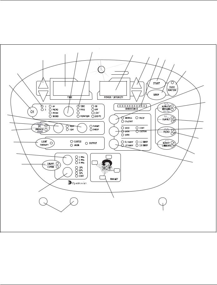
Dynatron Solaris® Physical Features
Before operating the Dynatron Solaris devices, acquaint yourself with the control panel by reviewing the illustrations and descriptions on the following pages. The numbered features in the diagrams correspond to the numbered descriptions. Before administering treatment to a patient, read the sections later in this manual that provide specific instructions for performing treatments, discussions of each modality, definitions of the available options, along with contraindications, warnings, and precautions for all modalities. Note that some options use “toggle” keys for making selections. More specific instructions for using toggle keys are provided later in this section.
Installation & Features
6
Dynatron Solaris® 700 Series
Solaris 701
5 |
9 |
10 |
11 |
4 |
|
|
|
|
|
1 |
|
|
|
|
|
|
|
|
2 |
|
|
|
3 |
|
|
|
27 |
8 |
|
|
|
|
|
|
17 |
|
|
|
18 |
26 |
|
|
16 |
Dynatron Solaris 701 Control Panel
Installation & Features
7
Dynatron Solaris® 700 Series
Solaris 705
|
5 |
8 |
9 |
|
10 |
|
|
4 |
|
|
|
|
11 |
27 |
1 |
|
|
|
|
|
|||
|
|
|
|
|
|
||
|
|
|
|
|
|
|
2 |
7 |
|
|
S |
L A R I S |
|
|
3 |
|
|
|
SERIES |
|
|
|
|
6 |
|
|
|
|
|
|
20 |
|
|
|
|
|
|
|
19 |
14 |
|
|
RATE/DUTY |
|
|
|
|
|
|
|
|
|
|
|
|
13 |
|
|
|
|
|
|
21 |
|
|
|
|
|
|
|
|
12 |
|
|
|
|
|
|
22 |
|
|
|
|
|
|
|
|
26 |
|
|
|
|
|
|
24 |
|
|
|
|
|
|
|
|
|
|
|
|
CH 2 |
|
|
25 |
|
|
|
|
|
|
|
|
|
|
|
CH 1 |
|
Dynatron |
|
23 |
|
|
|
|
CH 1 |
705 |
|
|
|
|
|
|
CH 2 |
|
|
|
CH1 |
|
CH2 |
|
|
|
HV |
|
|
|
|
|
15 |
|
|
|
|
28 |
|
|
|
|
29 |
|
|
|
|
|
|
|
|
|
Dynatron Solaris 705 Control Panel
Installation & Features
8
Dynatron Solaris® 700 Series
Solaris 706
|
5 |
8 |
9 |
|
10 |
|
|
|
|
|
|
|
11 |
27 |
|
||
4 |
|
|
|
|
|
1 |
||
|
|
|
|
|
|
|||
|
|
|
|
|
|
|
||
|
|
|
|
|
|
|
|
2 |
7 |
|
|
S |
L A R I S |
|
|
|
3 |
|
|
|
|
|
|
|||
|
|
|
SERIES |
|
|
|
|
|
6 |
|
|
|
|
|
|
|
20 |
|
|
|
|
|
|
|
|
19 |
14 |
|
|
RATE/DUTY |
|
|
|
|
|
|
|
|
|
|
|
|
|
|
13 |
|
|
|
|
|
|
|
21 |
|
|
|
|
|
|
|
|
|
12 |
|
|
|
|
|
|
|
22 |
|
|
|
|
|
|
|
|
|
26 |
|
|
|
|
|
|
|
24 |
|
|
|
|
|
|
|
|
|
|
|
|
|
CH 2 |
|
|
|
25 |
|
|
|
|
|
|
|
|
|
|
|
|
CH 1 |
|
Dynatron |
|
|
|
|
|
|
|
706 |
23 |
|||
|
|
|
|
|
||||
|
|
|
CH 2 |
CH 1 |
|
|||
CH1 |
|
CH2 |
CH3 |
|
CH4 |
|
HV |
|
|
|
|
|
15 |
|
|
|
|
|
|
|
28 |
|
|
29 |
|
|
|
|
|
|
|
|
|
||
Dynatron Solaris 706 Control Panel
Installation & Features
9
Dynatron Solaris® 700 Series
Solaris 708
|
5 |
8 |
9 |
|
10 |
|
|
4 |
|
|
|
|
11 |
27 |
1 |
|
|
|
|
|
|||
|
|
|
|
|
|
||
|
|
|
|
|
|
|
2 |
7 |
|
|
S |
L A R I S |
|
|
3 |
|
|
|
|
|
|||
|
|
|
SERIES |
|
|
|
|
6 |
|
|
|
|
|
|
20 |
|
|
|
|
|
|
|
19 |
14 |
|
|
RATE/DUTY |
|
|
|
|
|
|
|
|
|
|
|
|
13 |
|
|
|
|
|
|
21 |
|
|
|
|
|
|
|
|
12 |
|
|
|
|
|
|
22 |
|
|
|
|
|
|
|
|
26 |
|
|
|
|
|
|
24 |
|
|
|
|
|
|
|
|
17 |
|
|
|
|
|
|
25 |
|
|
|
|
CH 2 |
|
|
|
|
|
|
|
|
|
|
|
16 |
|
|
CH 1 |
|
Dynatron |
|
23 |
|
|
|
|
708 |
|
||
|
|
|
CH 2 |
CH 1 |
|
||
18 |
|
CH2 |
|
|
|
HV |
|
CH1 |
|
|
|
|
|
||
|
|
|
|
15 |
|
|
|
|
28 |
|
|
|
|
29 |
|
|
|
|
|
|
|
|
|
Dynatron Solaris 708 Control Panel
Installation & Features
10

Dynatron Solaris® 700 Series
Solaris 709
|
5 |
8 |
9 |
|
10 |
|
|
|
|
|
|
|
11 |
27 |
|
||
4 |
|
|
|
|
|
1 |
||
|
|
|
|
|
|
|||
|
|
|
|
|
|
|
||
|
|
|
|
|
|
|
|
2 |
7 |
|
|
S |
L A R I S |
|
|
|
3 |
|
|
|
|
|
|
|||
|
|
|
|
SERIES |
|
|
|
|
6 |
|
|
|
|
|
|
|
20 |
|
|
|
|
|
|
|
|
19 |
14 |
|
|
RATE/DUTY |
|
|
|
|
|
13 |
|
|
|
|
|
|
|
21 |
|
|
|
|
|
|
|
|
|
12 |
|
|
|
|
|
|
|
22 |
|
|
|
|
|
|
|
|
|
26 |
|
|
|
|
|
|
|
24 |
|
|
OUTPUT |
|
|
|
|
|
|
|
|
|
|
|
|
|
|
|
17 |
|
|
|
|
|
|
|
25 |
|
|
|
|
|
|
|
|
|
|
|
|
|
CH 2 |
|
|
|
|
16 |
|
|
CH 1 |
|
Dynatron |
|
|
23 |
|
|
|
|
709 |
|
|||
|
|
|
CH 2 |
CH 1 |
|
|||
18 |
|
CH2 |
CH3 |
|
CH4 |
|
HV |
|
CH1 |
|
|
|
|
||||
|
|
|
|
15 |
|
|
|
|
|
|
|
|
|
|
|
29 |
|
|
|
|
28 |
|
|
|
|
|
Dynatron Solaris 709 Control Panel
Installation & Features
11

Dynatron Solaris® 700 Series
General Selections
1.START: Press this key to start the treatment timer and treatment proceeds as set up. For probe treatments, the START key only activates the probe in preparation for the treatment. The treatment begins after the 1/0 (ON/OFF) key on the probe handle is pressed.
2.STOP: Pressing this key during a treatment IMMEDIATELY stops the output and sets the treatment time to zero for all modalities. To stop just one treatment only, press and hold the FUNCTION key while you press the STOP key, or simply reduce that channel’s treatment time to zero. For Light Probe treatments, press the 1/0 (ON/OFF) key located on the probe handle. On custom devices equipped with the remote stop feature, treatments may also be stopped by pressing the button on the REMOTE STOP cable, terminating all treatments.
3.PAUSE/FUNCTION: This key is used in combination with other key presses for accessing unique features including: Select polarity (High Volt, Microcurrent and Direct Current), audio volume control (Microcurrent), and to stop one treatment. Specific instructions for using this key are provided later in this manual.
Ultrasound: For Dynatron Solaris 701, 708 and 709 only: This key is also used to PAUSE an Ultrasound treatment. For the Solaris 708 and 709, first press the CHANNEL TOGGLE (CH) to select SOUND. For the D701, press the SOUND key. With Ultrasound as the focus, press PAUSE/FUNCTION; the Ultrasound output is stopped, the treatment time is paused, and the light on the PAUSE key is lighted. When this key is pressed again, the Ultrasound treatment countdown resumes and the light on the PAUSE key is off.
Combination Treatment: During a COMBO treatment, only the Ultrasound output and the treatment timer are stopped when you press PAUSE; the stim output continues.
Infrared Light Therapy Probe/Pad: Pressing the PAUSE/FUNCTION key will not pause a Solaris Light Therapy Probe treatment that is in progress. A Light Therapy Probe Treatment is paused by pressing the “1/0” key on the Light Probe handle. However, pressing the PAUSE/FUNCTION key will pause a pad treatment.
Please note: Following the completion of either a Pad or Probe treatment when using the Dynatron Booster Box, the practitioner must press the PAUSE/FUNCTION-STOP keys to exit the current focus (pad or probe) and switch to the opposite Light Therapy mode (pad or probe). For example: If the Booster Box is operational, and an Infrared Probe treatment has just timed out, the practitioner must press PAUSE/FUNCTION-STOP before using the CH toggle key to switch to an Infrared Light Pad treatment. PAUSE/FUNCTION-STOP would also have to be pressed following the Pad treatment to return back to a Probe treatment mode.
4.TIME ARROW KEYS: These UP/DOWN arrow keys are used to increase/decrease the treatment time or other parameters that are displayed in the TIME display.
5.TIME DISPLAY: This display is used to show the treatment time for one treatment at a time; the display shows treatment time for the selected channel (the selected channel is indicated by the GREEN LED—all other channels in use at the time will have YELLOW LEDs). The TIME display can also show the pulse rate and duration for Russian and Biphasic treatments as well as the frequencies for Interferential, Premodulated, and Microcurrent treatments, pulse duration for Direct Current treatments, and the pulse rate for High Volt. The treatment parameters for any treatment in progress may be displayed
Installation & Features
12
Dynatron Solaris® 700 Series
at any time by first using the CHANNEL TOGGLE key to choose the desired channel (the D701 will always automatically default to show the active modality), then using the TIME TOGGLE key to select the desired parameter (Time, Freq, Rate, Rate/Duty, Duration, On/Off).
6.CHANNEL TOGGLE KEY (CH): When a treatment is in progress, you can press this key to choose an output channel and display the parameters for the treatment being delivered by that channel. When an output light is GREEN, the displays show the settings for that output. The available options depend on the modality selected. When two or more treatments are in progress simultaneously, the TOGGLE KEY is used to select the output or channel you wish to view.
7.CHANNEL SELECTIONS: These lights indicate which output channels are currently in use. A solid GREEN light indicates current is being delivered to that channel; the time, intensity and other treatment parameters for that channel are also displayed. A solid YELLOW light indicates a channel is in use and delivering current, but the time, intensity, and treatment parameters are not displayed at this time (only one channel’s time and intensity may be displayed at a time). Flashing GREEN or flashing YELLOW indicates the OFF segment of a Biphasic, Russian, or High Volt treatment cycle. The channel’s intensity and other treatment parameters may only be modified when it has a GREEN indicator light. Press the CHANNEL TOGGLE key (CH) to select a channel to be viewed.
8.TIME TOGGLE KEY: Press this key to display various treatment parameters in the TIME display including Time (treatment time), Freq (frequency), Rate/Duty (pulse rate), Duration (pulse width), ON and OFF (current on/off cycle). Available options during a given treatment or treatment setup depend on the modality selected.
9.TIME GROUP SELECTIONS: These LEDs indicate the parameters that are displayed (one at a time) in the TIME display. The default selection is the treatment time. Press the TIME TOGGLE key to select the desired option (available options depend on the modality selected). When a parameter is selected, its indicator light is GREEN, its value is displayed in the TIME display above, and the TIME arrow keys may be used to change the value. The device returns to the TIME display after 10 seconds with no key presses.
10.POWER/INTENSITY DISPLAY (D701 POWER/DOSE DISPLAY): This window shows the treatment output in watts/cm2 or watts for Ultrasound, µA for Microcurrent and mA Direct Current, volts for High Volt and J/cm2 or Joules for Light therapy. For all other modalities it displays intensity from 0-99 in respect to the currently selected channel (the selected channel is indicated by the GREEN LED. All other channels in use at the time will have YELLOW LEDs). Press the CHANNEL TOGGLE key to select the desired channel to be viewed. The D701 will default to the active modality.
11.POWER/INTENSITY ARROW KEYS: These arrow keys are used to increase/decrease the intensity or power of one treatment. Changes made to power and intensity affect only the currently selected channel (the selected channel is indicated by the GREEN LED—all other channels in use at the time will have YELLOW LEDs). Press the CHANNEL TOGGLE key to select the desired output channel. The D701 will default to the active modality. The arrow keys may then be used to change the intensity or power for that channel.
Installation & Features
13

Dynatron Solaris® 700 Series
Interferential (IFC) / Premodulated Interferential (Premod) Selections:
12.IFC/PREMOD: Press this key once to begin setup of an Interferential treatment (the IFC LED is lighted); press this key twice to begin setup of a Premodulated treatment (the Premod LED is lighted). When you select IFC, a channel pair (CH1-2 or CH3-4) is automatically selected and the GREEN LED lights for the two auto-selected channels will be lighted. Connect two leads to the output jacks for the channels that are selected. When you select PREMOD, a single channel (1, 2, 3, or 4) is automatically selected and that channel’s GREEN LED will be lighted. Connect one lead to the output jack that corresponds to the channel indicated by the GREEN LED. Note: Channel 3-4 are only found on the Solaris 706 and 709 devices.
13.HIGH/LOW TOGGLE (used with Interferential, Premodulated and High Volt): Press this key one or more times to select the desired frequency range for Interferential and Premodulated treatments or the pulse rate range for High Volt treatments. The GREEN LED indicates the option selected. For example, HIGH will be displayed as the default selection. Press the HIGH/LOW TOGGLE key once to select LOW, press again to select HIGH/LOW ALTERNATING, and press again to select HIGH/LOW CONSECUTIVE. For High Volt treatments, you can select High or Low only, but not both. During a treatment, the current sweeps through the range(s) selected.
For Interferential and Premodulated, the HIGH frequency range is initially set at 80 to 150 Hz; and the LOW frequency range is 0 to 10 Hz. For High Volt, the HIGH pulse rate range is initially set at 80 to 120 Hz; and the LOW pulse rate range is 1 to 10 Hz. These frequency ranges may be modified for every treatment, if desired and new default settings for the device may also be saved. See treatment setup instructions later in this manual for a complete description of the options that may be selected.
14.TARGET/SWEEP TOGGLE: This key is pressed to select Target, Target Sweep, or Static treatment when an Interferential treatment is selected. The LED next to Target or Target Sweep will be lighted when selected. If both LEDs are OFF, the Static mode will be activated. If Target is selected, the Target pad is used to locate the exact treatment site.
15.TARGET PAD: For use during Interferential treatments when the “Target” option is selected. Touch the TARGET pad at different points on the pad to reach the precise treatment site. When you lift your finger from the Target pad, the selected point is locked until you change it again. This feature is used to place the point of interference at a specific site during an Interferential treatment.
Ultrasound Selections (Solaris 701, 708 and 709 only):
16.ULTRASOUND/COMBO D701, D708 and 709: Press this key once to begin setup of an Ultrasound treatment (the Sound LED on this key is lighted as well as the Sound LED in the channel indicator area); press this key twice to begin setup of a combination treatment (the COMBO LED is lighted as well as the Sound LED and a single Channel LED in the channel indicator area). When either of these options is chosen, the soundhead should first be plugged into the Ultrasound output jack on the side panel. For combination treatments, the special COMBO lead wire should be attached to the output jack selected for that treatment and the banana plug should be plugged in where indicated on the right side of the device behind the Ultrasound jack. In the COMBO mode, the electrotherapy treatment is delivered through the soundhead and through a single electrode which is placed on the patient. Only single-channel electrotherapy options are available in the
COMBO mode, i.e. Premod, Russian, Biphasic, and High Volt.
Installation & Features
14

Dynatron Solaris® 700 Series
ULTRASOUND/COMBO D701: The D701 is designed with a Combo Input Jack on the right side of the device to which a separate Dynatron Stim unit can be attached, allowing the stim to flow through the soundhead. After attaching the Stim unit set up the Ultrasound and Stim treatments separately.
17.ULTRASOUND FREQUENCY TOGGLE: This key is pressed one or more times to select the desired Ultrasound frequency; 1 MHz, 2 MHz, or 3 MHz.
18.ULTRASOUND DUTY CYCLE TOGGLE: This key is pressed one or more times to select the desired duty cycle for Ultrasound treatment. Options are 10, 20, or 50 percent, or Continuous.
Russian / Biphasic / High Volt Selections:
19.BIPHASIC/RUSSIAN: Press this key once to begin setup of a Biphasic treatment (the Biphasic LED is lighted); press this key twice to begin setup of a Russian treatment (the Russian LED is lighted). Biphasic and Russian treatments use a single channel (1, 2, 3 or 4) when the Normal mode is selected; and a channel pair (1-2 or 3-4) when the Reciprocal or Co-contraction mode is selected. Channels 3-4 pair treatments are only available on the Solaris 706 and the Solaris 709.
20.TREATMENT MODE TOGGLE (for Biphasic and Russian Treatment Modes): Press this key one or more times to select Normal, Co-Contraction, or Reciprocal contraction. The output channel is automatically selected. When Normal is selected, one output jack only is selected.
When Co-contraction or Reciprocal is selected, a channel pair is selected (either channels 1-2 or channels 3-4). Connect the patient lead wire(s) to the output jack(s) for the channel(s) selected. Channels 3-4 pair treatments are only available on the Solaris 709 and the Solaris 706.
21.HIGH VOLT: Press this key to begin setup of a High Voltage Pulsed Stimulation treatment (the High Volt LED is lighted). The HV output channel is automatically selected (the LED for the channel selected is GREEN). Connect the patient lead wire to the HV output jack indicated by the green LED. Press the Channel Toggle key to select HV Probe treatment, if desired. For probe treatments, increase (+) and decrease (-) intensity indicator switches are located on the probe handle.
HIGH VOLT POLARITY: Polarity on a High Volt treatment defaults to negative (-). To select or change the polarity of a High Volt treatment, hold down the FUNCTION KEY and press the HI VOLT key one or more times to select positive only (the “+” LED is lighted), negative polarity only (the “-” LED is lighted), or dual polarity (both (+) and (-) LEDs are lighted).
22.CONTRACTION/REST CYCLE TOGGLE (for Russian, Biphasic, and High Volt treatments): Press this key one or more times to select the desired contraction/rest (on/off) cycle. Available cycles include 10/10, 10/30, 10/50, Continuous and Custom. The CUSTOM DUTY CYCLE is a new feature that allows you to customize the treatment by selecting from an ON time from 3to 20 seconds, and an OFF time from 3 to 120 seconds. The OFF time cannot be less than the ON time. In addition, you can modify the pulse rate, the pulse duration, and the ramp time. The first value indicates the on-time in seconds, and the second value indicates the off-time. For example; 10/30 indicates the current is on (muscle is contracting) for 10 seconds, and current is off (muscle is relaxed) for 30 seconds. With Continuous mode, current is applied continuously with no off cycle. The continuous duty cycle is not recommended for
Installation & Features
15

Dynatron Solaris® 700 Series
electrical muscle stimulation, but may be used for settings that are intended to effect other results than a muscle contraction.
23.RAMP TOGGLE: (for Russian, Biphasic, and High Volt treatments): This key is pressed to select the ramp time. The ramp time is applied before and after the “On” segment of the cycle (it provides both a ramp up and a ramp down). Available ramp times are .5, 1, 1.5, and 2 seconds. NOTE: The ramp up and down time is the same.
Microcurrent Selections:
24.MICRO: Press this key to begin setup of a Microcurrent treatment. This key is also used to turn the conductance tone OFF and ON after a Microcurrent treatment is started. When the MICRO key is pressed, Channel 1 is automatically selected for the default electrodes treatment and the LED for that channel is lighted. For a Microcurrent treatment setup with electrodes, connect the patient lead wire to the CHANNEL 1 output jack.
For a Microcurrent probes treatment, press the CHANNEL TOGGLE key to select PROBE after selecting MICRO and both the PROBE and MICRO LEDs are lighted. For a Microcurrent Probe treatment connect the MultiStim probe to the STIM PROBE OUTPUT JACK on the side panel of the device.
NOTE: Channel 1 is committed to the Microcurrent output during a probes treatment as well as during a treatment with electrodes, and is not available for use by any other modality while any Microcurrent treatment is in progress.
MICROCURRENT POLARITY: To select or change the polarity of a microcurrent treatment, use the MICRO key together with the FUNCTION key. Press and continue holding the FUNCTION key while pressing the MICRO key one or more times to select positive only (the “+” LED is lighted), negative polarity only (the “-” LED is lighted), or dual polarity (both LEDs are lighted).
MICROCURRENT AUDIO TONE: The audible tone is defaulted to ON for probes treatments and OFF for electrode treatments, but may be changed. After the Microcurrent treatment has started the MICRO key acts as a toggle key to turn the tone ON and OFF. Press MICRO to turn the tone ON or OFF.
You may also adjust the tone volume after the treatment has started. To adjust the volume, PRESS and HOLD the FUNCTION key. Then while continuing to press the FUNCTION key, use the POWER/INTENSITY ARROW keys to raise or lower the volume until a comfortable volume setting is found. The POWER/INTENSITY display will temporarily show an incremental value representing the volume selection. You must continue holding the FUNCTION key down while adjusting the volume. When you release the FUNCTION key, the POWER/INTENSITY display returns to its normal display.
Direct Current Selections:
25.DIRECT CURRENT: This key selects the Direct Current modality. Since this modality is a probes-only treatment, the MULTISTIM probe must be plugged into the STIM
PROBE JACK before a treatment may proceed. All control for intensity and actuation is from switches located on the probe. Intensity is displayed in mA (maximum 20 mA). Duration is displayed in mSec in the TIME DISPLAY with pulse duration selection from 0.1 mSec to 500 mSec. To change the polarity, hold down the FUNCTION KEY and press the DIRECT CURRENT button. Pressing one or more times will toggle through the options of positive, or negative.
Installation & Features
16

Dynatron Solaris® 700 Series
Light Therapy Selections:
26.LIGHT THERAPY: Caution: Always begin by plugging the Light Therapy Probe or
Pad into the base console unit before turning ON the device. Please note, when using a Dynatron Xp pad, a Solaris Booster Box is required. Press the Light Therapy key to begin setup for either a probe or pad treatment.
PROBE: The Solaris device will recognize the type of probe that has been inserted into the Solaris console. The CLUSTER LED or LASER LED (SLD on the D701) and the PROBE LED are lighted.
PAD: After pressing LIGHT THERAPY, press the CH toggle key to complete setup for a Pad treatment. The PROBE LED will go OFF, while the CLUSTER LED will remain lighted.
START: Pressing START on the base Solaris console will immediately begin an Infrared Light Pad treatment; however, for a Probe treatment pressing START on the console will only activate the Probe in preparation for a treatment. The YELLOW LED on the Light Therapy Probe handle will be lighted. A Probe treatment will begin when the 1/0 (ON/OFF) key on the Probe handle is pressed and the LED on the probe handle is GREEN. A green LED next to OUTPUT on the faceplate will indicate that a LIGHT THERAPY treatment is in progress.
CAUTION: Vents surrounding the Light Therapy probes must be kept clear and free of any obstruction at all times. Do Not cover the XP pad with towels or blankets during treatment.
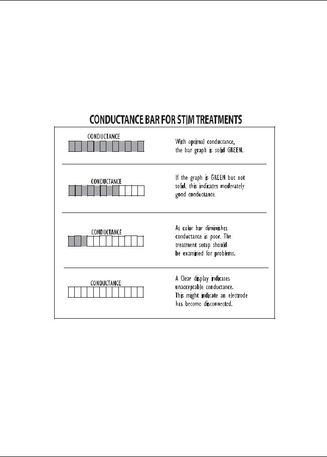
Conductance
27.The Solaris devices continuously measures conductance during electrical stim treatments for Interferential, Premod, and Microcurrent to ensure that the treatment outcome is optimal and to minimize the possibility of patient discomfort due to poor conductance and/or changes in current density. As conductance is measured, Solaris displays the results in graph form on the CONDUCTANCE bar located on the front panel of the device. Optimum conductance is displayed as a GREEN bar filling the entire graph. If the green bar only partially fills the graph area, the conductance is at a percentage of optimum.
Conductance: Conductance is how readily electrical current is passed from the electrode to the skin surface during a treatment. Conductance affects current density. A worn electrode that does not conduct the current evenly over its entire surface will have “hot spots” where a greater amount of current flows through a smaller area which means the current density is higher at that point than elsewhere on the electrode. “Hot Spots” can lead to patient discomfort. Never risk patient comfort by using worn electrodes or lead wires.
Intensity: The intensity level is a convenient incremental measurement. However, raising the intensity increases the current delivered to the patient but does not improve conductance.
Current Density: Current density is the amount of current that passes through a given area of the electrode. Current density varies depending on the size of the electrode, the conductance and the intensity setting, and has an effect on patient comfort. With proper setup and good accessories, current is dispersed evenly over the entire surface of the electrode. The smaller the electrode, the greater the density of the current delivered through the area. To reduce current density and improve patient comfort, you can either use larger electrodes, or a lower intensity setting, or both.
Installation & Features
17
Dynatron Solaris® 700 Series
During a Microcurrent probe treatment, the graph is also useful in observing conductance changes since the goal of some microcurrent treatments is to increase conductance (reduce resistance/impedance) at a given point.
During an Ultrasound treatment, the graph is used to assist with monitoring patient coupling. This feature is described in the section of this manual entitled Ultrasound section of this manual entitled “Patient Coupling.”
If the number of Green displayed segments begin to decrease on the graph during a treatment, it is important to determine the cause of the poor conductance. Remember with poor conductance you may inadvertently increase current density at a small point under the electrode and cause patient discomfort. Following are some considerations to insure proper conductance.
The bar graph uses twelve lighted segments to indicate best conductance, and no lighted segments to indicate poorest conductance.
•Check to be sure electrodes are not worn or that self-adhesive electrodes have not lost their adhesiveness. These are the most common causes of poor current delivery. Both selfadhesive and carbon electrodes eventually lose their ability to conduct current effectively. See “Electrotherapy Usage Cautions” in this manual for recommended intensity settings and usage limits.
•Check to ensure the entire surface of the poly adhesive electrode is adhering.
•Self-adhesive electrodes do not require sterilization, however, electrodes should be clean and hydrated (see package instructions or “Self-Adhesive Electrodes” section of this manual).
•Check to be sure electrodes are not worn or that self-adhesive electrodes have not lost their adhesiveness. These are the most common causes of poor current delivery. Both selfadhesive and carbon electrodes eventually lose their ability to conduct current effectively.
Installation & Features
18
Dynatron Solaris® 700 Series
•See “Electrotherapy Usage Cautions” in this manual for recommended intensity settings and usage limits.
•Check to ensure the entire surface of the poly adhesive electrode is adhering.
•Self-adhesive electrodes do not require sterilization, however, electrodes should be clean and hydrated (see package instructions or “Self-Adhesive Electrodes” section of this manual).
•Check to be sure the snap adapters haven’t fallen off or that the lead wire has not become disconnected from the electrodes or the device.
•Make sure carbon electrodes have a secure connection with the pin ends of the leads. Over time the carbon electrodes may become too loose to use safely and the electrodes must be replaced.
•Check for corrosion on lead ends.
•Make sure carbon electrodes are adequately moistened and free from build-up to allow complete contact across the surface of the electrode.
•Observe the electrode placement. Some areas of the patient’s body conduct current better than others. In areas where resistance is high you may be unable to obtain optimum conductivity.
•Check the dryness of the patient’s skin. Dry skin does not conduct current well.
•Check to see if the electrodes do not adhere properly when a patient shifts position during a treatment. Worn electrodes could become loose and a significant change in conductance could result.
Remember to treat at the patient’s comfort level. It is not important to reach a given intensity level. It is only important to set the treatment at a level that is comfortable to the patient. See “Electrotherapy Usage Cautions in this manual for suggested intensity limits.
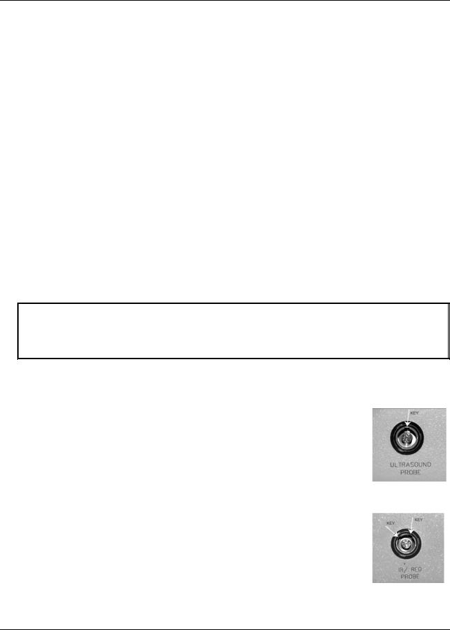
Output Connectors and Jacks
Connectors and jacks on the Solaris device are “Keyed/Locking” connectors (see illustration to the right and on the following page). Use caution when inserting the connectors into the output jacks. When the keys are properly aligned, the connector and jack will slide together smoothly and exactly. When removing the connector, the locking mechanism is released when the outside connector shell is pulled away from the device. Do not force the connector or damage to the pins may occur. This damage is not covered by warranty.
Note: Devices that have been custom ordered with the Patient REMOTE STOP cable will have an additional jack located on the back of the base unit. The remote stop is controlled by the patient during unattended therapy to allow the patient to stop the treatment at any time. When the button on the remote stop cable is pressed, output for all stim modalities and pad treatments is stopped and the tone sounds briefly.
During Combo treatments, both sound and stim outputs are stopped.
“Keyed” Probe Jack
Installation & Features
19
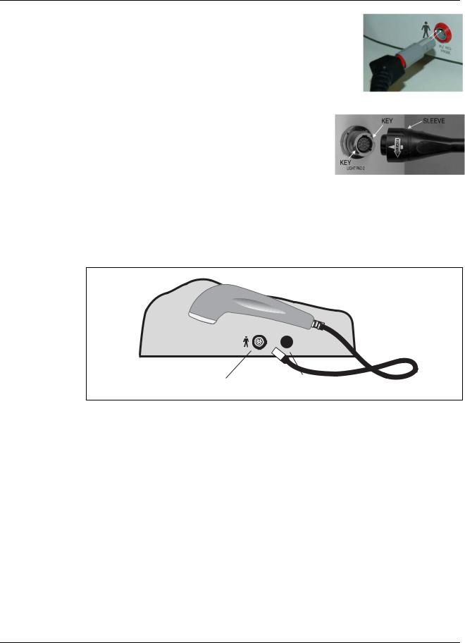
Dynatron Solaris® 700 Series
Keyed” Probe Connectors
When attaching the probe, align the raised portion of the connector with the notched jack opening. When removing the
probe connector, the locking mechanism is released when the outside connector shell is gently pulled away from the base unit.
“Keyed” Pad Connectors
The Pad connector is attached by aligning the connector with the keyed openings in the jack and pushing the connector into the jack. To remove the connector, turn the sleeve to the left in the direction of the “Release” arrow and gently remove the connector. Do not use force when attaching or removing the connector.
28. OUTPUT JACK CHANNELS 1, 2, 3, and 4: These are the output jacks for delivering Interferential,
Premodulated, Russian, Biphasic, and Microcurrent treatments. These channels are located in the front of the device. Front (left to right as you face the device).
29.HIGH VOLT OUTPUT JACK CHANNEL HV. This is the output jack dedicated to delivering High Volt pad treatments, located in front on the far right side.
IR/Red Probe (31) |
Stim Probe (30) |
|
Solaris Left Side View
30.STIM PROBE JACK - MICROCURRENT/HV/DC PROBES TREATMENTS: The universal MultiStim probe plugs into this jack for Microcurrent, High Volt or DC probe therapy. After the probe is connected and either Microcurrent or High Volt keys have been pressed, press the TIME TOGGLE key to select PROBE. If the Direct Current modality is selected, the device will automatically default to PROBE. See illustration above.
31.DYNATRON LIGHT THERAPY (IR/RED) OUTPUT JACK: This output jack is designed to accommodate a single probe. When one of the Dynatron Solaris probes is
connected, the device will recognize the probe and will auto calculate time/dosage (J/cm2), Joules, and total treatment time. See illustration above.
32.COMBINATION TREATMENT JACK: The special combo lead wire for combination treatments is plugged into this jack located on the right side of the device for a combination treatment setup providing stim output through the Ultrasound head of the D708, D709. For combination treatments using the D701, the Dynatron stim device is plugged into the Combination Treatment Jack using a pin-to-banana adapter.
The special lead wire on the D708 and D709 is also plugged into the jack on the front of
Installation & Features
20

Dynatron Solaris® 700 Series
the device which has been selected for the specific COMBO treatment. See combination treatment instructions later in this manual for detailed information regarding combination treatment setup. See illustration on the following page.
Combo Input (32)
Ultrasound Probe (33)
Solaris Right Side View
33.ULTRASOUND OUTPUT JACK (Ultrasound models only): The applicator soundhead plugs into this jack for Ultrasound therapy. Located on the right side of the device. See diagram on previous page.
Power Switch / Battery
34.POWER 1/0 (ON/OFF) SWITCH: Located on the back of the unit this switch is labeled “1” and “0”. Set the switch to “1” for ON; set the switch to “0” for OFF.
battery (35)
power (34)
Solaris Back Panel
35.BATTERY: This jack may be used to supply power to the device using an optional battery pack. More information about the optional battery operation is provided later in this manual. (See illustration on the previous page).
Booster Box / Booster Box Jacks
36.BOOSTER BOX / BOOSTER BOX JACKS (The Dynatron Booster Box is required for use with the Dynatron Xp Pad on all Solaris 700 Series devices): The Dynatron Booster Box is engineered to provide the additional power needed to operate the Dynatron Xp Infrared Light pad. The Booster Box mirrors the outline of the outer-contours of the Solaris console and stands approximately 2” in height. The flat upper surface of the Booster Box is designed with four pre-molded circular receptacles at each corner in which to place the rubber feet of the Solaris console, thus allowing the two units to fit
Installation & Features
21
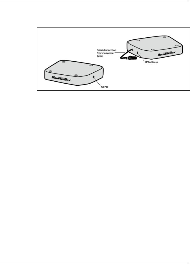
Dynatron Solaris® 700 Series
together with the appearance of a single device. The two units are electrically and functionally connected by a communication cable (labeled SOLARIS CONNECTION) attached to the Booster Box and designed to be plugged into the IR/RED output jack located on the left side of the main Solaris console.
Booster Box and Jacks
The Booster Box has two output jacks: A LIGHT PROBE jack located on the left side of the device in front of the communication cable and a LIGHT PAD output jack located on the right side of the Booster Box. Please note: Only one Light Therapy treatment
(either probe or pad) may be given at a time.
Instructions for Using Toggle Keys
Toggle keys are used to make selections from two or more options in a given area. Toggle keys are pressed one or more times to make a desired selection. A GREEN light (LED) next to the toggle key shows the option that has been selected. Pressing the toggle key one or more times allows you to scan through the available options.
Each toggle key has unique capabilities. Most toggle keys allow only one selection. For example, the Ramp toggle key requires you to select just one of the four ramp times available. However, some toggle keys allow you to select two options. For example, in Interferential you can press the HIGH/LOW TOGGLE key once to select High, press again to select Low, and press again to select both High and Low.
The following is a list of all the toggle keys available with each modality:
IFC and Premod
•Target/Sweep (IFC only)
•High/Low Frequency Ranges
Russian and Biphasic Stim
•Treatment mode
•Contraction/Rest cycle
•Ramp Time
High Volt Stim
•Contraction/Rest cycle
•Ramp Time
•Polarity
•High/Low Pulse Rate Ranges
•Channel toggle to select Pads/HV Channel or Probes Treatment (during setup only)
Installation & Features
22
 Loading...