


®
DYNATRON SOLARIS
700 SERIES
SERVICE MANUAL
Dynatron Solaris® 700 Series
CAUTION: Federal law restricts these devices for sale by or on the order of a physician,
chiropractor, physical therapist, or dentist licensed by the law of the state in which said
person practices to use or order the use of the devices.
Risk of burns and fire - Do not use near conductive materials such as metal bed parts, inner
spring mattresses and the like.
DANGER - Explosion Hazard: Do not use in the presence of flammable anesthetics.
IMPORTANT: Before treating a patient with any Dynatron Solaris® Device, see the
“Contraindications, Warnings, and Precautions” in this manual.
INDICATIONS FOR USE
ELECTROTHERAPY:
• Electrical muscle stimulation therapy (Russian, Biphasic, High Volt) for:
1. relaxation of muscle spasm;
2. prevention or retardation of disuse atrophy;
3. increasing local blood circulation;
4. muscle re-education;
5. immediate post surgical stimulation of calf muscles to prevent venous thrombosis
6. maintaining or increasing range of motion.
• Transcutaneous electrical nerve stimulation and Interferential Current Therapy (Interferential,
Premodulated, High Volt, Microcurrent) for:
Symptomatic relief of chronic intractable and/or management of post-traumatic or post-surgical pain.
DIRECT CURRENT THERAPY:
Direct Current is indicated for relaxation of muscle spasms.
ULTRASOUND THERAPY:
Ultrasound therapy is intended to generate deep heat within body tissues for the treatment of selected medical
conditions such as relief of pain, muscle spasms, and joint contractures, but not for the treatment of
malignancies.
LIGHT THERAPY:
Light therapy provides topical heating for temporary increase in blood circulation, temporary relief of minor
muscle and joint aches, pain and stiffness, relaxation of muscles, and treatment of muscle spasms and minor
pain and stiffness associated with arthritis.
The Solaris D890 laser product is designated as class 1M during all procedures of Operation and
Maintenance.
AVOID INADVERTENT EXPOSURE TO POTENTIALLY HAZARDOUS LIGHT
PATENT PENDING
02-07_14
REV.
INVENTORY MKT299
Dynatron Solaris
Revised
Dynatronics Corporation
7030 Park Centre Drive
Salt Lake City, UT 84121
www.dynatronics.com
ALL RIGHTS RESERVED
®
Operator’s Manual
February 2007
© Copyright 2003
(801) 568-7000
(800) 874-6251
ii
Authorized European
Representative:
Emergo Group, Inc.
Molenstraat 15
2513 BH The Hague
The Netherlands
Tel: 31.70.345.8570
Fax: 31.70.346.7299
0344

Dynatron Solaris® 700 Series
Table of Contents
SECTION I
INTRODUCTION
Introduction to the Dynatron Solaris
Summary of Features by Device ............................................................................................................ 2
Simplified Setup ..................................................................................................................................... 3
Before You Treat a Patient ..................................................................................................................... 3
Installation and Features............................................................................................................................ 4
Unpacking .............................................................................................................................................. 4
Standard Components............................................................................................................................. 4
Soundheads............................................................................................................................................. 5
Optional Accessories.............................................................................................................................. 5
Dynatron Solaris
General Selections................................................................................................................................ 12
Conductance ......................................................................................................................................... 17
Output Connectors and Jacks ............................................................................................................... 19
Power Switch / Battery......................................................................................................................... 21
Booster Box / Booster Box Jacks ......................................................................................................... 21
Instructions for Using Toggle Keys ..................................................................................................... 22
Channel Output Indicator Lights.......................................................................................................... 23
Current Limit........................................................................................................................................ 24
Current Limit Warning......................................................................................................................... 24
Lead Wires / Electrodes........................................................................................................................ 25
Lead Wires ........................................................................................................................................... 25
Test Leads............................................................................................................................................. 25
“LEAD” Warning - No Patient Current ............................................................................................... 26
Carbon Electrodes ................................................................................................................................ 27
Self-Adhesive Electrodes .....................................................................................................................28
®
Physical Features...................................................................................................... 6
®
700 Series................................................................................... 2
Quick Reference of Special Key Presses ................................................................................................. 29
SECTION II
OPERATION AND TREATMENT INSTRUCTIONS
Electrotherapy Information ..................................................................................................................... 32
and Usage Cautions................................................................................................................................... 32
iii

Dynatron Solaris® 700 Series
Interferential / Premodulated Instructions .............................................................................................35
Basic Interferential / Premod Setup ......................................................................................................35
Detailed Interferential / Premodulated Setup........................................................................................35
Interferential and Premodulated Modality Information ........................................................................40
Interferential (Quadpolar) Therapy.......................................................................................................40
Premodulated (Bipolar) Therapy ..........................................................................................................40
Target ....................................................................................................................................................41
Why Is Target Better?...........................................................................................................................41
Target Sweep ........................................................................................................................................41
Interferential Electrode Placement........................................................................................................42
Interferential / Premodulated Default Settings......................................................................................42
Interferential Default Settings...............................................................................................................42
Premodulated Default Settings..............................................................................................................43
Biphasic / Russian Instructions ................................................................................................................44
Basic Biphasic / Russian Setup.............................................................................................................44
Detailed Biphasic / Russian Setup ........................................................................................................45
Biphasic / Russian Modality Information .............................................................................................49
Russian Stimulation ..............................................................................................................................49
Biphasic Stimulation.............................................................................................................................49
Biphasic / Russian Parameters ..............................................................................................................49
Biphasic / Russian Default Settings ......................................................................................................51
High Volt Instructions...............................................................................................................................52
Set Up High Volt Treatment with Electrodes .......................................................................................52
Set Up High Volt Probe Treatment.......................................................................................................53
Basic High Volt Setup ..........................................................................................................................53
High Volt Treatment Time....................................................................................................................54
Detailed High Volt Setup......................................................................................................................54
High Volt Modality Information...........................................................................................................59
High Volt Waveform ............................................................................................................................59
High Volt Settings.................................................................................................................................59
High Volt Default Settings....................................................................................................................60
High Volt Waveform Specifications.....................................................................................................60
Microcurrent Instructions ........................................................................................................................61
How To Use The MultiStim Probe For Microcurrent Treatments........................................................61
Basic Microcurrent Setup .....................................................................................................................62
Microcurrent Treatment Time...............................................................................................................63
Detailed Microcurrent Setup.................................................................................................................63
Microcurrent Modality Information......................................................................................................66
iv

Dynatron Solaris® 700 Series
Microcurrent Waveforms .....................................................................................................................66
Microcurrent Guidelines....................................................................................................................... 66
Microcurrent Default Settings .............................................................................................................. 67
Direct Current Instructions ..................................................................................................................... 68
Direct Current Setup............................................................................................................................. 68
Detailed Direct Current Setup .............................................................................................................. 68
Direct Current Modality Information ................................................................................................... 70
Direct Current Probes Therapy............................................................................................................. 70
Direct Current Waveforms ................................................................................................................... 70
Direct Current Cautions........................................................................................................................ 70
Direct Current Default Specifications .................................................................................................. 71
Direct Current Default Settings ............................................................................................................ 71
Infrared Light Therapy Operating Instructions.................................................................................... 72
Infrared Light Therapy Treatment Setup.............................................................................................. 73
Detailed Treatment Setup ..................................................................................................................... 73
Infrared Light Therapy Treatment Notes.............................................................................................. 77
Infrared Light Therapy Modality Information .....................................................................................78
Infrared Light Therapy Basic Vocabulary............................................................................................ 78
Solaris Light Therapy Probes & Dynatron Xp Pad Specifications ...................................................... 78
Infrared Light Therapy Probe Overlays ............................................................................................... 81
Infrared Light Therapy Probe/Pad Default Settings............................................................................. 81
Ultrasound Instructions............................................................................................................................ 82
Soundhead Warming ............................................................................................................................ 83
Turn Soundhead Warming Off / On..................................................................................................... 83
Coupling ............................................................................................................................................... 83
Patient Coupling Display...................................................................................................................... 83
Ultrasound Coupling Bar Graph........................................................................................................... 84
Head Temperature Hot Display............................................................................................................84
Display Watts or W/cm
2
....................................................................................................................... 85
Basic Ultrasound Setup ........................................................................................................................ 86
Basic Ultrasound Setup ........................................................................................................................ 86
Detailed Ultrasound Setup.................................................................................................................... 86
Ultrasound Modality Information......................................................................................................... 89
Selecting the Appropriate Soundhead ..................................................................................................89
Penetration of Ultrasound Waves......................................................................................................... 90
Types of Delivery................................................................................................................................. 90
Treatment Time .................................................................................................................................... 91
Treatment Intensity............................................................................................................................... 91
v

Dynatron Solaris® 700 Series
Frequency of Treatment........................................................................................................................91
Usage Cautions – Combination Treatments..........................................................................................92
Potential for Burns or Periosteal Pain...................................................................................................92
Soundhead Optimization (D701, D708, D709) ....................................................................................92
Adding or Replacing Soundheads.........................................................................................................92
Ultrasound Calibration Procedures .......................................................................................................94
Problem Solving ...................................................................................................................................96
Soundhead Temperature Too Hot.........................................................................................................96
Cooling the Soundhead.........................................................................................................................97
Whirlpool Treatments ...........................................................................................................................97
Soundhead Temperature Too Cold .......................................................................................................97
No Soundhead.......................................................................................................................................97
Other Error Messages in the Display ....................................................................................................98
Ultrasound Specifications (Dynatron Solaris 701, 708, and 709 only) ................................................98
Ultrasound Default Settings..................................................................................................................98
Ultrasound Regulation and Technical Information...............................................................................99
Beam Profiles......................................................................................................................................100
Combination Therapy Instructions .......................................................................................................103
Comboplus™ .......................................................................................................................................103
Stim Through the Soundhead..............................................................................................................104
Combination Therapy Setup ...............................................................................................................104
Modify Treatment ...............................................................................................................................107
Combination Default Settings.............................................................................................................107
Simultaneous Treatments .......................................................................................................................108
Set Up A Second Treatment................................................................................................................108
Modify Simultaneous Treatments.......................................................................................................109
Stop One Treatment ............................................................................................................................109
SECTION III
CONTRAINDICATIONS, WARNINGS, AND PRECAUTIONS
Contraindications, Warnings, & Precautions for Interferential, Premodulated, Russian,
Biphasic, High Voltage Pulsed Stimulation, and Direct Current Treatments ...................................112
Contraindications ................................................................................................................................112
Warnings.............................................................................................................................................112
Precautions..........................................................................................................................................113
Treatment Setup Warnings .................................................................................................................113
Adverse Effects...................................................................................................................................114
Use Only Dynatronics Accessories.....................................................................................................114
vi

Dynatron Solaris® 700 Series
Contraindications, Warnings, & Precautions for Microcurrent ........................................................ 115
Contraindications................................................................................................................................ 115
Warnings ............................................................................................................................................ 115
Precautions ......................................................................................................................................... 115
Adverse Reactions.............................................................................................................................. 116
Contraindications, Warnings, & Precautions for Ultrasound Treatment......................................... 117
Contraindications................................................................................................................................ 117
Precautions ......................................................................................................................................... 118
Warnings ............................................................................................................................................ 118
Contraindications, Warnings, & Precautions for Solaris Light Therapy Treatments ..................... 119
Contraindications................................................................................................................................ 119
Precautions and Warnings .................................................................................................................. 119
Laser Safety (D890 Probe) ................................................................................................................. 120
SECTION IV
TECHNICAL INFORMATION
Setting Defaults .......................................................................................................................................124
Save New Defaults ............................................................................................................................. 124
Restore Factory Defaults .................................................................................................................... 124
Battery Operation ................................................................................................................................... 126
Battery Requirements ......................................................................................................................... 126
Battery Life......................................................................................................................................... 127
General Specifications ............................................................................................................................ 128
Dynatron Solaris Specifications ......................................................................................................... 128
Environmental Conditions.................................................................................................................. 128
Safety Features of the Dynatron Solaris............................................................................................. 128
Care and Cleaning Instructions .......................................................................................................... 128
Suggested Maintenance Schedule ...................................................................................................... 129
Routine Ultrasound Calibration Inspections for Solaris..................................................................... 130
Software Updates ............................................................................................................................... 130
Returning a Unit for Repair................................................................................................................ 131
Definition of Symbols and Labeling ..................................................................................................132
Equipment Classification.................................................................................................................... 133
Disposal of Equipment and Accessories ............................................................................................ 133
Dynatronics Electrodes and Lead Wires ............................................................................................ 134
Additional Technical Information Available (for Technicians Only) ................................................ 135
vii

Dynatron Solaris® 700 Series
SECTION V
SCHEMATICS AND QC CHECK LISTS
Quality Check Sheet ................................................................................................................................138
Ultrasound Quality Check Sheet.........................................................................................................140
Schematic Drawings ...........................................................................................................................141
Index… .....................................................................................................................................................159
Limited Warranty ...................................................................................................................................162
viii

Dynatron Solaris® 700 Series
SECTION I
INTRODUCTION
1
Introduction

Dynatron Solaris® 700 Series
Introduction to the
Dynatron Solaris
The Dynatron Solaris 700 Series offers the practitioner a wide range of treatment options.
These devices provide Interferential and Premodulated therapy; High Voltage pulsed
stimulation; Russian and Biphasic therapies; Microcurrent and Direct Current treatments; and
Infrared Light Probe applications. The Solaris 700 Series devices may, with the use of the
®
Dynatron
In addition, the Solaris 701, 708, and 709 include Ultrasound and the Dynatronics
Comboplus
The 700 Series devices include the standard advantages of Dynatronics engineering, such as
customizable treatments, electrode conductance meters and the popularTarget feature. In
addition all units offer the option of battery operation, making the devices truly portable. The
manufacturer’s warranty for these devices is two years (see full warranty details at the back
of this manual).
This manual provides operator information and instructions for five Solaris models: the 701,
705, 706, 708, and 709. The section that discusses Ultrasound and Comboplus treatments
applies only to the Dynatron 701, 708 and 709 models. All other sections of this manual
apply to all Dynatron Solaris devices.
Summary of Features by Device
Electrotherapy
IFC X X X X
Premod X X X X
Biphasic X X X X
Russian X X X X
High Volt X X X X
Microcurrent X X X X
Direct Current X X X X
Combo Electrotherapy/Ultrasound X X
Light Therapy
Ultrasound
Special Features
Electrotherapy Channels 4 2 4 2
High Volt Channel 1 1 1 1
Stim Probe Channel X X X X
Infrared/Laser Light Therapy Port X X X X X
Conductance Meter X X X X
*
*Note: The Dynatron Solaris Booster Box must be used in conjunction with the Dynatron Xp Light pad on all
Solaris 700 Series devices. Software upgrades are required on all devices manufactured prior to September 2005.
Booster Box, operate the Dynatron® Xp™, a powerful 8”X10” Infrared Light Pad.
™ feature providing almost unlimited combinations of treatment options.
Feature 701 709 708 706 705
Booster Box / Light Pad Capability X X X X X
®
700 Series
X X X X X
X X X
2

Simplified Setup
The unique design of the Solaris front panel means treatment setup has never been easier. A
few simple key presses are all you need to fully set up a treatment. The careful grouping of
available options for each modality ensures that you can easily see and select from the
appropriate options for that modality.
Each modality offers default settings which are automatically preset when the modality is
selected—saving time in the treatment setup. You can change these defaults to match your
own most common treatment setups reducing setup time to a matter of seconds.
Before You Treat a Patient
Before administering a treatment to a patient with the Solaris devices, you should familiarize
yourself with all the operating instructions for the modality used, as well as the
contraindications, warnings, and precautions for that modality.
You should also read the general information about each of the modalities provided in this
manual. In addition to this information, consult other published sources for additional
application and safety instructions regarding use of each type of therapy.
Dynatron Solaris® 700 Series
Introduction
3

Installation and Features
Unpacking
When you receive the unit, immediately unpack it and all accessories and check for possible
damage, obvious or concealed. In case of damage, immediately notify the freight carrier and
take any steps necessary to file a claim for the damage sustained. Do not destroy or discard
the shipping carton. The carton should be reused if the device must be shipped for any
reason. The carton is specially designed to protect the unit from shipping damage. Improper
packaging of the unit during transport can result in damage and invalidate the warranty.
Complete the warranty registration form located at the back of this manual and return
it to Dynatronics within 30 days of purchase. This is essential to insure you are not
billed for services that are covered by the warranty policy. Warranty registration
should include serial numbers for both the device and soundheads.
Connect the AC power cord, which is equipped with a hospital grade, UL listed plug, to a
properly grounded 110/120V 60 Hz AC outlet (the device will automatically switch to
220/240V 50 Hz when connected to a power source with that voltage). The power cord must
also be firmly plugged into the device itself. When the cord is properly connected, it can not
be easily pulled out. Do not place the cord or the device in a place where the cord could be
tripped over or accidentally pulled out of its socket during a treatment.
If Infrared Light Therapy probes or pads are being used in conjunction with a Solaris
device and/or Booster Box, they should be plugged into the Solaris console and/or
Booster Box prior to powering-on the device(s).
Read the operating instructions in this manual before proceeding with a treatment.
Standard Components
The following accessories are included with the Solaris units:
Qty Part No. Description
One of the following devices:
1 D701 Solaris 701
1 D705 Solaris 705
1 D706 Solaris 706
1 D708 Solaris 708
1 D709 Solaris 709
1 7B0241 Power Cord (black)
1 9G0011 Operator's Manual
1 7B0268 Protocol Reference Manual for Electrotherapy & Ultrasound
1 7B0217 Dynagel Ultrasound Gel 100 ml sample - Solaris 701, 708 and
Dynatron Solaris® 700 Series
(Guffey, 2003)
709 only
Installation & Features
4

Qty Part No. Description
2 7B0232 120” double leads (2 red) - Solaris 706 and 709 only
2 7B0233 120” double leads (2 black) - Solaris 706 and 709 only
1 7B0230
7B0231 72” double lead (1 black) - Solaris 705 and 708 only
1
72” double lead (1 red) - Solaris 705 and 708 only
1 7B0234 COMBOplus lead wires –Solaris 708 and 709 only
1 7B0265 Ultra Polys
(pkg. of 4)
1 8E0017A MultiStim Point Tip Attachment
1 7B0250 MultiStim probe (requires one or more applicators)
1 8E0018 High Volt applicator 5/8” round
1 8E0019 High Volt applicator 2”x1-1/2”
2 7B0063
3” round carbon electrodes (2 red)
2 7B0065 3” round carbon electrodes (2 black)
4 7B0210 Sponge fabric for use with 3” carbon electrodes
1 7B0193 Sponge Pocket 1 1/2” x 2”
1 7B0192 Sponge Pocket 5/8”
2 DW248 2.5” x 48” straps (pkg. of 2) Solaris 706 and 709 only
1 DW248 2.5” x 48” straps (pkg. of 2) Solaris 705 and 708 only
1 7B0191 5” x 8” dispersive electrode for High Volt (gray)
1 7B0201 Sponge Fabric for use with 5”x 8” dispersive electrodes
1 8D0027 Microcurrent Ground Probe
1 7B0079 Banana-to-Pin Adapter (black)
Soundheads
The Solaris devices may be purchased with one or more applicator soundheads in the
following sizes:
Part No. Size Frequencies
9GSH02 2 cm
9GSH05 5 cm
9GSH10 10 cm
Optional Accessories
The following optional and replacement accessories may be purchased from Dynatronics or
from your Dynatronics dealer:
Part No. Description
D880 Dynatron 880 Cluster Probe
D890 Dynatron 890 Light Therapy Probe
D405 Dynatron 405 Infrared Cluster Probe
D881 Dynatron 880Plus Infrared Cluster Probe
9G0104 Protective Eyewear (D405)
Xp Dynatron Xp Infrared Light Pad
XpB Dynatron Solaris Booster Box
7B0271 Light Therapy Applications Manual (Enwemeka & Pöntinen)
7B0272 Hard Side Carrying Case for Solaris Units
7B0273 Soft Side Carrying Case
7B0208 2” diameter carbon electrodes (red)
7B0209 2” diameter carbon electrodes (gray)
7B0063 3” diameter carbon electrodes (red)
Dynatron Solaris® 700 Series
Note: The following are not applicable to the D701.
™ Self-adhesive electrodes 2” x 4” w/pin connector
2
Operates at 1, 2, and 3 MHz
2
Operates at 1, 2, and 3 MHz
2
Operates at 1, 2, and 3 MHz
(Booster Box required)
Installation & Features
5

Dynatron Solaris® 700 Series
Part No. Description
7B0065 3” diameter carbon electrodes (gray)
7B0059 3” x 5” carbon electrodes (red)
7B0061 3” x 5” carbon electrodes (gray)
7B0067 1.5” x 2.0” carbon electrodes (red)
7B0069 1.5” x 2.0” carbon electrodes (gray)
7B0260 2” x 4” Ultra Polys
connector)
7B0261 2” x 2” Ultra Polys
(with snap or pin connector)
7B0077 Bifurcated extension lead wire for High Volt use
7B0082 Pin-to-Banana adapter (black)
7B0079 Banana-to-Pin Adapter (black)
7B0001 Snap adapter
5LTRGEL Ultrasound Coupling Gel (5 liter container)
9G0079 Light Probe Covers (Disposable / 25 per package)
8A0061 Remote Stop Cable Assembly (Applicable only to customized,
special order units).
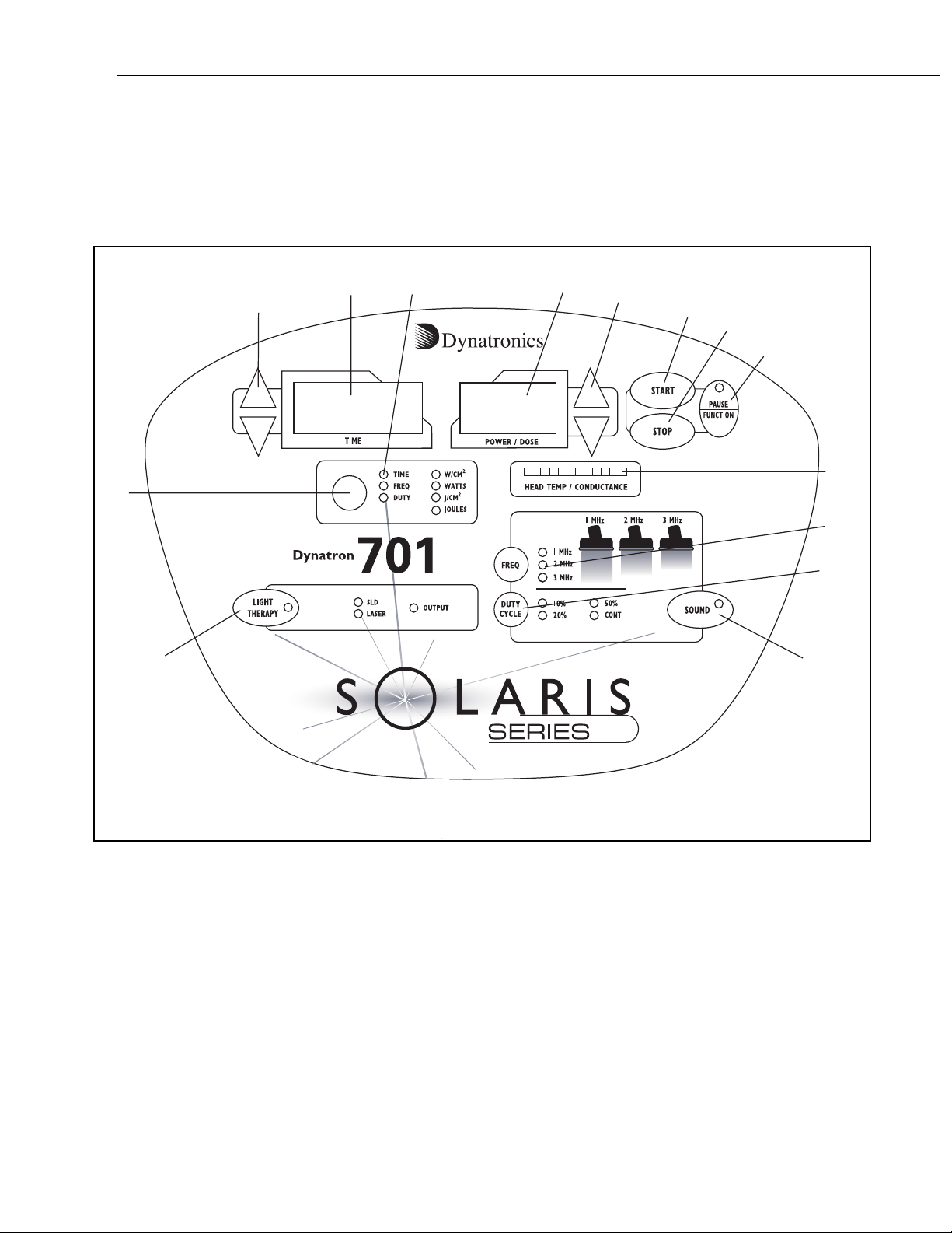
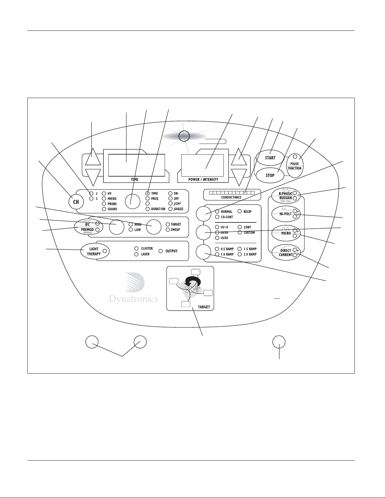
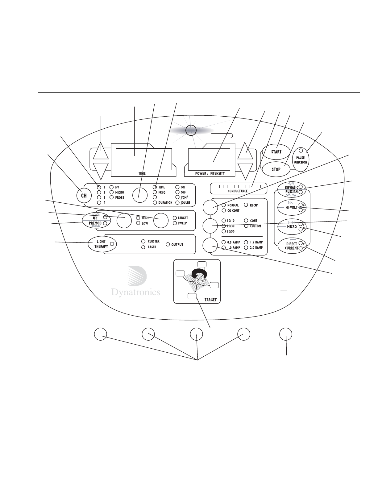
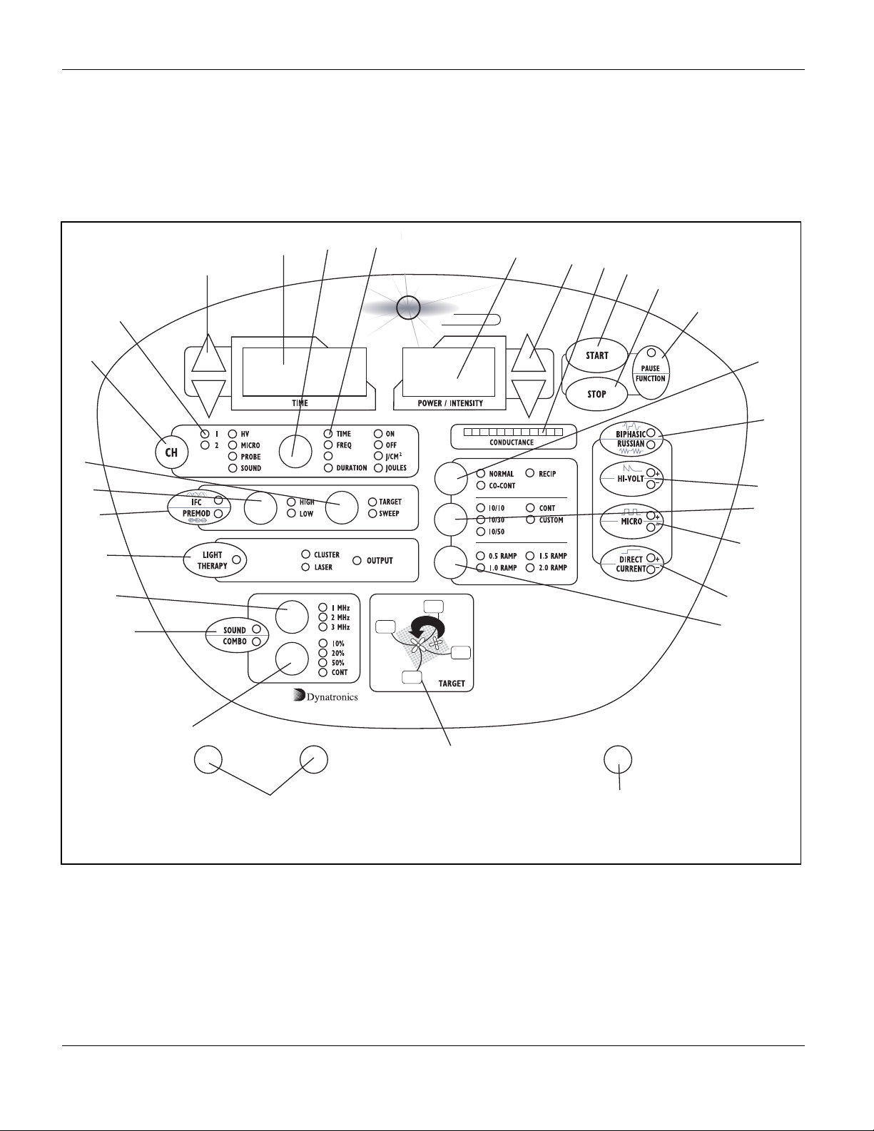
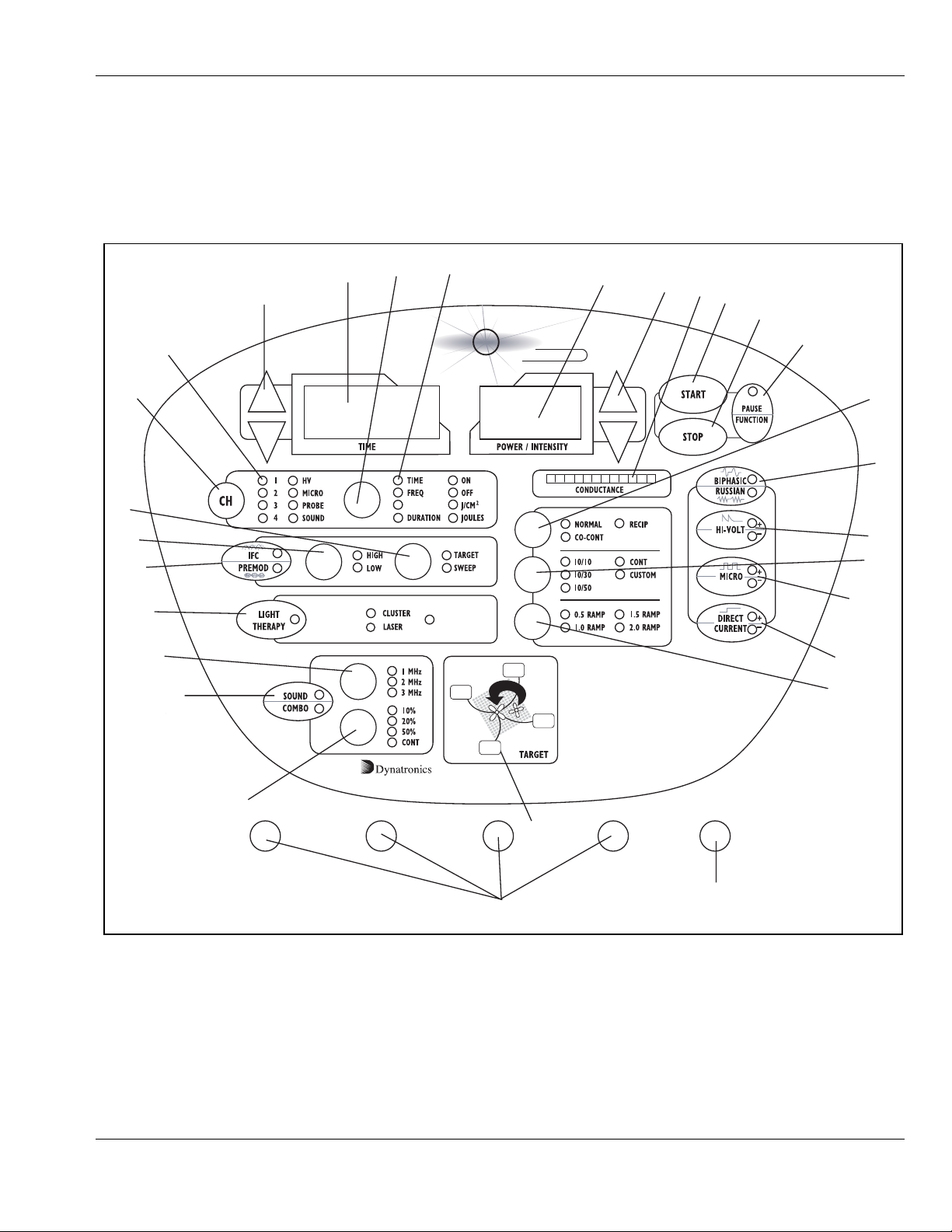
Dynatron Solaris® Physical Features
Before operating the Dynatron Solaris devices, acquaint yourself with the control panel by
reviewing the illustrations and descriptions on the following pages. The numbered features in
the diagrams correspond to the numbered descriptions. Before administering treatment to a
patient, read the sections later in this manual that provide specific instructions for performing
treatments, discussions of each modality, definitions of the available options, along with
contraindications, warnings, and precautions for all modalities. Note that some options use
“toggle” keys for making selections. More specific instructions for using toggle keys are
provided later in this section.
™ adhesive electrodes (with snap or pin
™ square adhesive electrodes
Installation & Features
6
4
8
26
Dynatron Solaris 701 Control Panel
Dynatron Solaris® 700 Series
Solaris 701
5
9
10
11
1
2
3
27
17
18
16
Installation & Features
7
Dynatron Solaris® 700 Series
Solaris 705
14
13
RATE/DUTY
9
S LARIS
CH 1
SERIES
CH 2
10
Dynatron
11
27
1
2
3
20
19
21
22
24
25
23
5
4
7
6
12
26
8
CH1 CH2 HV
Dynatron Solaris 705 Control Panel
Installation & Features
28
CH 2
CH 1
15
705
29
8
Dynatron Solaris® 700 Series
Solaris 706
14
13
RATE/DUTY
9
S LARIS
CH 1
SERIES
CH 2
10
Dynatron
11
27
1
2
3
20
19
21
22
24
25
23
5
4
7
6
12
26
8
CH1 CH2 CH3 CH4 HV
Dynatron Solaris 706 Control Panel
CH 2
28
CH 1
15
706
29
Installation & Features
9
4
7
6
14
13
12
26
17
16
18
CH1 CH2 HV
Dynatron Solaris 708 Control Panel
28
Dynatron Solaris® 700 Series
Solaris 708
RATE/DUTY
9
S LARIS
CH 1
SERIES
CH 2
CH 1
CH 2
15
10
Dynatron
708
11
27
29
1
2
3
20
19
21
22
24
25
23
5
8
Installation & Features
10
4
7
6
16
18
CH1 CH2 CH3 CH4 HV
14
13
12
26
17
Dynatron Solaris 709 Control Panel
Dynatron Solaris® 700 Series
Solaris 709
RATE/DUTY
9
S LARIS
OUTPUT
CH 1
SERIES
CH 2
CH 1
CH 2
15
28
10
Dynatron
709
11
27
1
2
3
20
19
21
22
24
25
23
29
5
8
11
Installation & Features

General Selections
1. START
probe treatments, the START key only activates the probe in preparation for the
treatment. The treatment begins after the 1/0 (ON/OFF) key on the probe handle is
pressed.
2. STOP: Pressing this key during a treatment IMMEDIATELY stops the output and sets
the treatment time to zero for all modalities. To stop just one
hold the FUNCTION key while you press the STOP key, or simply reduce that channel’s
treatment time to zero. For Light Probe treatments, press the 1/0 (ON/OFF) key located
on the probe handle. On custom devices equipped with the remote stop feature,
treatments may also be stopped by pressing the button on the REMOTE STOP cable,
terminating all treatments.
3. PAUSE/FUNCTION
accessing unique features including: Select polarity (High Volt, Microcurrent and Direct
Current), audio volume control (Microcurrent), and to stop one treatment. Specific
instructions for using this key are provided later in this manual.
Ultrasound: For Dynatron Solaris 701, 708 and 709 only: This key is also used to
PAUSE an Ultrasound treatment. For the Solaris 708 and 709, first press the CHANNEL
TOGGLE (CH) to select SOUND. For the D701, press the SOUND key. With
Ultrasound as the focus, press PAUSE/FUNCTION; the Ultrasound output is stopped, the
treatment time is paused, and the light on the PAUSE key is lighted. When this key is
pressed again, the Ultrasound treatment countdown resumes and the light on the PAUSE
key is off.
Combination Treatment: During a COMBO treatment, only the Ultrasound output and the
treatment timer are stopped when you press PAUSE; the stim output continues.
Infrared Light Therapy Probe/Pad: Pressing the PAUSE/FUNCTION key will not pause a
Solaris Light Therapy Probe treatment that is in progress. A Light Therapy Probe
Treatment is paused by pressing the “1/0” key on the Light Probe handle. However,
pressing the PAUSE/FUNCTION key will pause a pad treatment.
Please note: Following the completion of either a Pad or Probe treatment when using
the Dynatron Booster Box, the practitioner must press the PAUSE/FUNCTION-STOP
keys to exit the current focus (pad or probe) and switch to the opposite Light Therapy
mode (pad or probe). For example: If the Booster Box is operational, and an
Infrared Probe treatment has just timed out
PAUSE/FUNCTION-STOP before using the CH toggle key to switch to an Infrared
Light Pad treatment. PAUSE/FUNCTION-STOP would also have to be pressed
following the Pad treatment to return back to a Probe treatment mode.
4. TIME ARROW KEYS
treatment time or other parameters that are displayed in the TIME display.
5. TIME DISPLAY
time; the display shows treatment time for the selected channel (the selected channel is
indicated by the GREEN LED—all other channels in use at the time will have YELLOW
LEDs). The TIME display can also show the pulse rate and duration for Russian and
Biphasic treatments as well as the frequencies for Interferential, Premodulated, and
Microcurrent treatments, pulse duration for Direct Current treatments, and the pulse rate
for High Volt. The treatment parameters for any treatment in progress may be displayed
: Press this key to start the treatment timer and treatment proceeds as set up. For
Dynatron Solaris® 700 Series
treatment only, press and
: This key is used in combination with other key presses for
, the practitioner must press
: These UP/DOWN arrow keys are used to increase/decrease the
: This display is used to show the treatment time for one treatment at a
Installation & Features
12

Dynatron Solaris® 700 Series
at any time by first using the CHANNEL TOGGLE key to choose the desired channel
(the D701 will always automatically default to show the active modality), then using the
TIME TOGGLE key to select the desired parameter (Time, Freq, Rate, Rate/Duty,
Duration, On/Off).
6. CHANNEL TOGGLE KEY (CH
): When a treatment is in progress, you can press this
key to choose an output channel and display the parameters for the treatment being
delivered by that channel. When an output light is GREEN, the displays show the
settings for that output. The available options depend on the modality selected. When
two or more treatments are in progress simultaneously, the TOGGLE KEY is used to
select the output or channel you wish to view.
7. CHANNEL SELECTIONS
: These lights indicate which output channels are currently in
use. A solid GREEN light indicates current is being delivered to that channel; the time,
intensity and other treatment parameters for that channel are also displayed. A solid
YELLOW light indicates a channel is in use and delivering current, but the time, intensity,
and treatment parameters are not displayed at this time (only one channel’s time and
intensity may be displayed at a time). Flashing GREEN or flashing YELLOW indicates the
OFF segment of a Biphasic, Russian, or High Volt treatment cycle. The channel’s intensity
and other treatment parameters may only be modified when it has a GREEN indicator light.
Press the CHANNEL TOGGLE key (CH) to select a channel to be viewed.
8. TIME TOGGLE KEY
: Press this key to display various treatment parameters in the
TIME display including Time (treatment time), Freq (frequency), Rate/Duty (pulse rate),
Duration (pulse width), ON and OFF (current on/off cycle). Available options during a
given treatment or treatment setup depend on the modality selected.
9. TIME GROUP SELECTIONS
: These LEDs indicate the parameters that are displayed
(one at a time) in the TIME display. The default selection is the treatment time. Press
the TIME TOGGLE key to select the desired option (available options depend on the
modality selected). When a parameter is selected, its indicator light is GREEN, its value
is displayed in the TIME display above, and the TIME arrow keys may be used to
change the value. The device returns to the TIME display after 10 seconds with no key
presses.
10. POWER/INTENSITY DISPLAY
the treatment output in watts/cm
Direct Current, volts for High Volt and J/cm
(D701 POWER/DOSE DISPLAY): This window shows
2
or watts for Ultrasound, µA for Microcurrent and mA
2
or Joules for Light therapy. For all other
modalities it displays intensity from 0-99 in respect to the currently selected channel (the
selected channel is indicated by the GREEN LED. All other channels in use at the time
will have YELLOW LEDs). Press the CHANNEL TOGGLE key to select the desired
channel to be viewed. The D701 will default to the active modality.
11. POWER/INTENSITY ARROW KEYS
: These arrow keys are used to increase/decrease
the intensity or power of one treatment. Changes made to power and intensity affect only
the currently selected channel (the selected channel is indicated by the GREEN LED—all
other channels in use at the time will have YELLOW LEDs). Press the CHANNEL
TOGGLE key to select the desired output channel. The D701 will default to the active
modality. The arrow keys may then be used to change the intensity or power for that
channel.
13
Installation & Features

Dynatron Solaris® 700 Series
Interferential (IFC) / Premodulated Interferential (Premod) Selections:
12. IFC/PREMOD: Press this key once to begin setup of an Interferential treatment (the IFC
LED is lighted); press this key twice to begin setup of a Premodulated treatment (the
Premod LED is lighted). When you select IFC, a channel pair (CH1-2 or CH3-4) is
automatically selected and the GREEN LED lights for the two auto-selected channels
will be lighted. Connect two leads to the output jacks for the channels that are selected.
When you select PREMOD, a single channel (1, 2, 3, or 4) is automatically selected and
that channel’s GREEN LED will be lighted. Connect one lead to the output jack that
corresponds to the channel indicated by the GREEN LED. Note: Channel 3-4 are only
found on the Solaris 706 and 709 devices.
13. HIGH/LOW TOGGLE (used with Interferential, Premodulated and High Volt): Press
this key one or more times to select the desired frequency range for Interferential and
Premodulated treatments or the pulse rate range for High Volt treatments. The GREEN
LED indicates the option selected. For example, HIGH will be displayed as the default
selection. Press the HIGH/LOW TOGGLE key once to select LOW, press again to select
HIGH/LOW ALTERNATING, and press again to select HIGH/LOW CONSECUTIVE.
For High Volt treatments, you can select High or Low only, but not both. During a
treatment, the current sweeps through the range(s) selected.
For Interferential and Premodulated, the HIGH frequency range is initially set at 80 to
150 Hz; and the LOW frequency range is 0 to 10 Hz. For High Volt, the HIGH pulse rate
range is initially set at 80 to 120 Hz; and the LOW pulse rate range is 1 to 10 Hz. These
frequency ranges may be modified for every treatment, if desired and new default settings
for the device may also be saved. See treatment setup instructions later in this manual for
a complete description of the options that may be selected.
14. TARGET/SWEEP TOGGLE: This key is pressed to select Target, Target Sweep, or
Static treatment when an Interferential treatment is selected. The LED next to Target or
Target Sweep will be lighted when selected. If both LEDs are OFF, the Static mode will
be activated. If Target is selected, the Target pad is used to locate the exact treatment
site.
15. TARGET PAD: For use during Interferential treatments when the “Target” option is
selected. Touch the TARGET pad at different points on the pad to reach the precise
treatment site. When you lift your finger from the Target pad, the selected point is
locked until you change it again. This feature is used to place the point of interference at
a specific site during an Interferential treatment.
Ultrasound Selections (Solaris 701, 708 and 709 only):
16. ULTRASOUND/COMBO D701, D708 and 709: Press this key once to begin setup of an
Ultrasound treatment (the Sound LED on this key is lighted as well as the Sound LED in
the channel indicator area); press this key twice to begin setup of a combination treatment
(the COMBO LED is lighted as well as the Sound LED and a single Channel LED in the
channel indicator area). When either of these options is chosen, the sound- head should
first be plugged into the Ultrasound output jack on the side panel. For combination
treatments, the special COMBO lead wire should be attached to the output jack selected
for that treatment and the banana plug
should be plugged in where indicated on the right
side of the device behind the Ultrasound jack. In the COMBO mode, the electrotherapy
treatment is delivered through the soundhead and through a single electrode which is
placed on the patient. Only single-channel electrotherapy options are available in the
COMBO mode, i.e. Premod, Russian, Biphasic, and High Volt.
Installation & Features
14

Dynatron Solaris® 700 Series
ULTRASOUND/COMBO D701: The D701 is designed with a Combo Input Jack on the
right side of the device to which a separate Dynatron Stim unit can be attached, allowing
the stim to flow through the soundhead. After attaching the Stim unit set up the
Ultrasound and Stim treatments separately.
17. ULTRASOUND FREQUENCY TOGGLE: This key is pressed one or more times to
select the desired Ultrasound frequency; 1 MHz, 2 MHz, or 3 MHz.
18. ULTRASOUND DUTY CYCLE TOGGLE: This key is pressed one or more times to
select the desired duty cycle for Ultrasound treatment. Options are 10, 20, or 50 percent,
or Continuous.
Russian / Biphasic / High Volt Selections:
19. BIPHASIC/RUSSIAN: Press this key once to begin setup of a Biphasic treatment (the
Biphasic LED is lighted); press this key twice to begin setup of a Russian treatment (the
Russian LED is lighted). Biphasic and Russian treatments use a single channel (1, 2, 3 or
4) when the Normal mode is selected; and a channel pair (1-2 or 3-4) when the
Reciprocal or Co-contraction mode is selected. Channels 3-4 pair treatments are only
available on the Solaris 706 and the Solaris 709.
20. TREATMENT MODE TOGGLE (for Biphasic and Russian Treatment Modes): Press
this key one or more times to select Normal, Co-Contraction, or Reciprocal contraction.
The output channel is automatically selected. When Normal is selected, one output jack
only is selected.
When Co-contraction or Reciprocal is selected, a channel pair is selected (either channels
1-2 or channels 3-4). Connect the patient lead wire(s) to the output jack(s) for the
channel(s) selected. Channels 3-4 pair treatments are only available on the Solaris 709
and the Solaris 706.
21. HIGH VOLT: Press this key to begin setup of a High Voltage Pulsed Stimulation
treatment (the High Volt LED is lighted). The HV output channel is automatically
selected (the LED for the channel selected is GREEN). Connect the patient lead wire to
the HV output jack indicated by the green LED. Press the Channel Toggle key to select
HV Probe treatment, if desired. For probe treatments, increase (+) and decrease (-)
intensity indicator switches are located on the probe handle.
HIGH VOLT POLARITY: Polarity on a High Volt treatment defaults to negative (-). To
select or change the polarity of a High Volt treatment, hold down the FUNCTION KEY
and press the HI VOLT key one or more times to select positive only (the “+” LED is
lighted), negative polarity only (the “-” LED is lighted), or dual polarity (both (+) and (-)
LEDs are lighted).
22. CONTRACTION/REST CYCLE TOGGLE (for Russian, Biphasic, and High Volt
treatments
): Press this key one or more times to select the desired contraction/rest
(on/off) cycle. Available cycles include 10/10, 10/30, 10/50, Continuous and Custom.
The CUSTOM DUTY CYCLE is a new feature that allows you to customize the
treatment by selecting from an ON time from 3to 20 seconds, and an OFF time from 3 to
120 seconds. The OFF time cannot be less than the ON time. In addition, you can
modify the pulse rate, the pulse duration, and the ramp time. The first value indicates the
on-time in seconds, and the second value indicates the off-time. For example; 10/30
indicates the current is on (muscle is contracting) for 10 seconds, and current is off
(muscle is relaxed) for 30 seconds. With Continuous mode, current is applied
continuously with no off cycle. The continuous duty cycle is not recommended for
15
Installation & Features

Dynatron Solaris® 700 Series
electrical muscle stimulation, but may be used for settings that are intended to effect
other results than a muscle contraction.
23. RAMP TOGGLE: (for Russian, Biphasic, and High Volt treatments): This key is pressed
to select the ramp time. The ramp time is applied before and after the “On” segment of
the cycle (it provides both a ramp up and a ramp down). Available ramp times are .5, 1,
1.5, and 2 seconds. NOTE: The ramp up and down time is the same.
Microcurrent Selections:
24. MICRO: Press this key to begin setup of a Microcurrent treatment. This key is also used
to turn the conductance tone OFF and ON after a Microcurrent treatment is started.
When the MICRO key is pressed, Channel 1 is automatically selected for the default
electrodes treatment and the LED for that channel is lighted. For a Microcurrent
treatment setup with electrodes, connect the patient lead wire to the CHANNEL 1 output
jack.
For a Microcurrent probes treatment, press the CHANNEL TOGGLE key to select
PROBE after selecting MICRO and both the PROBE and MICRO LEDs are lighted. For
a Microcurrent Probe treatment connect the MultiStim probe to the STIM PROBE
OUTPUT JACK on the side panel of the device.
NOTE: Channel 1 is committed to the Microcurrent output during a probes treatment as
well as during a treatment with electrodes, and is not available for use by any other
modality while any Microcurrent treatment is in progress.
MICROCURRENT POLARITY: To select or change the polarity of a microcurrent
treatment, use the MICRO key together with the FUNCTION key. Press and continue
holding the FUNCTION key while pressing the MICRO key one or more times to select
positive only (the “+” LED is lighted), negative polarity only (the “-” LED is lighted), or
dual polarity (both LEDs are lighted).
MICROCURRENT AUDIO TONE: The audible tone is defaulted to ON for probes
treatments and OFF for electrode treatments, but may be changed. After the
Microcurrent treatment has started the MICRO key acts as a toggle key to turn the tone
ON and OFF. Press MICRO to turn the tone ON or OFF.
You may also adjust the tone volume after the treatment has started. To adjust the
volume, PRESS and HOLD the FUNCTION key. Then while continuing to press the
FUNCTION key, use the POWER/INTENSITY ARROW keys to raise or lower the
volume until a comfortable volume setting is found. The POWER/INTENSITY display
will temporarily show an incremental value representing the volume selection. You must
continue holding the FUNCTION key down while adjusting the volume. When you
release the FUNCTION key, the POWER/INTENSITY display returns to its normal
display.
Direct Current Selections:
25. DIRECT CURRENT: This key selects the Direct Current modality. Since this modality
is a probes-only treatment, the MULTISTIM probe must be plugged into the STIM
PROBE JACK before a treatment may proceed. All control for intensity and actuation
is from switches located on the probe. Intensity is displayed in mA (maximum 20 mA).
Duration is displayed in mSec in the TIME DISPLAY with pulse duration selection from
0.1 mSec to 500 mSec. To change the polarity, hold down the FUNCTION KEY and
press the DIRECT CURRENT button. Pressing one or more times will toggle through
the options of positive, or negative.
Installation & Features
16

Light Therapy Selections:
26. LIGHT THERAPY: Caution: Always begin by plugging the Light Therapy Probe or
Conductance
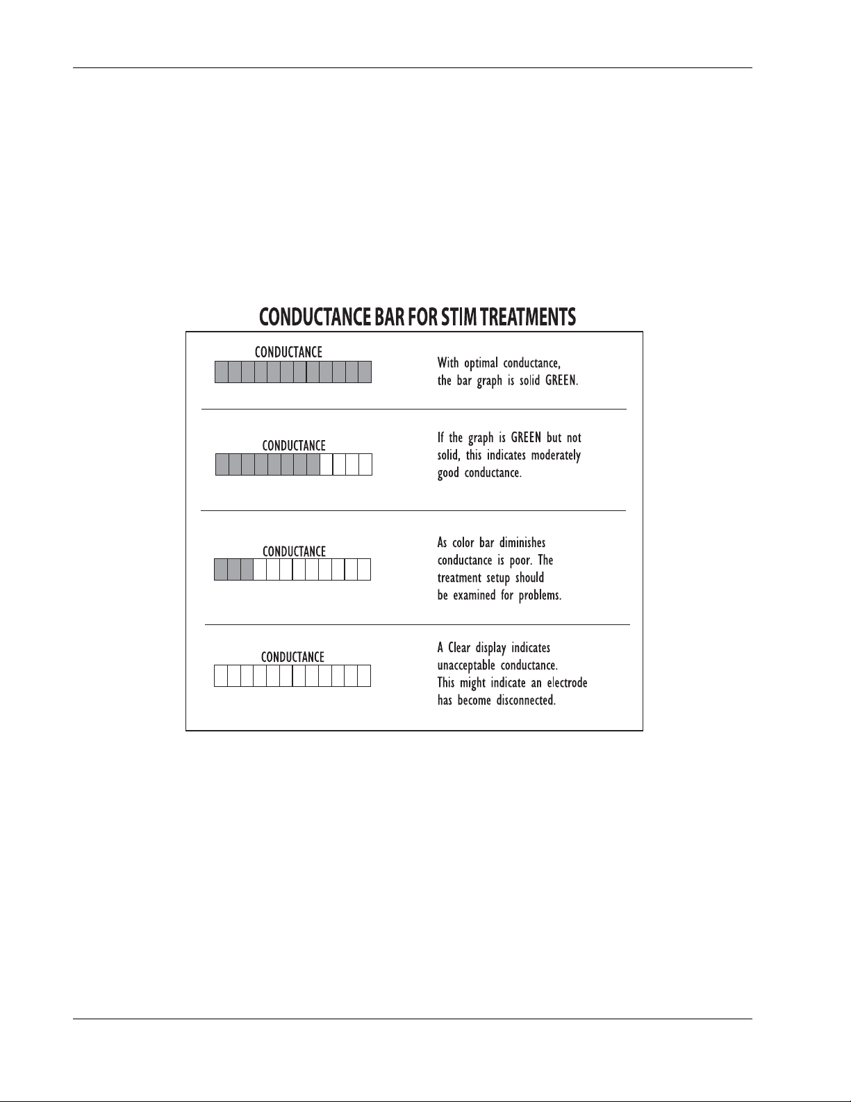
27. The Solaris devices continuously measures conductance during electrical stim treatments
Dynatron Solaris® 700 Series
Pad into the base console unit before turning ON the device. Please note, when
using a Dynatron Xp pad, a Solaris Booster Box is required. Press the Light Therapy
key to begin setup for either a probe or pad treatment.
PROBE: The Solaris device will recognize the type of probe that has been inserted into
the Solaris console. The CLUSTER LED or LASER LED (SLD on the D701) and the
PROBE LED are lighted.
PAD: After pressing LIGHT THERAPY, press the CH toggle key to complete setup for
a Pad treatment. The PROBE LED will go OFF, while the CLUSTER LED will remain
lighted.
START: Pressing START on the base Solaris console will immediately begin an
Infrared Light Pad treatment; however, for a Probe treatment pressing START on the
console will only activate the Probe in preparation for a treatment. The YELLOW LED
on the Light Therapy Probe handle will be lighted. A Probe treatment will begin when
the 1/0 (ON/OFF) key on the Probe handle is pressed and the LED on the probe handle is
GREEN. A green LED next to OUTPUT on the faceplate will indicate that a LIGHT
THERAPY treatment is in progress.
CAUTION: Vents surrounding the Light Therapy probes must be kept clear and free of
any obstruction at all times. Do Not cover the XP pad with towels or blankets during
treatment.
for Interferential, Premod, and Microcurrent to ensure that the treatment outcome is
optimal and to minimize the possibility of patient discomfort due to poor conductance
and/or changes in current density. As conductance is measured, Solaris displays the
results in graph form on the CONDUCTANCE bar located on the front panel of the
device. Optimum conductance is displayed as a GREEN bar filling the entire graph. If
the green bar only partially fills the graph area, the conductance is at a percentage of
optimum.
Conductance: Conductance is how readily electrical current is passed from the electrode
to the skin surface during a treatment. Conductance affects current density. A worn
electrode that does not conduct the current evenly over its entire surface will have “hot
spots” where a greater amount of current flows through a smaller area which means the
current density is higher at that point than elsewhere on the electrode. “Hot Spots” can
lead to patient discomfort. Never risk patient comfort by using worn electrodes or lead
wires.
Intensity: The intensity level is a convenient incremental measurement. However,
raising the intensity increases the current delivered to the patient but does not improve
conductance.
Current Density: Current density is the amount of current that passes through a given
area of the electrode. Current density varies depending on the size of the electrode, the
conductance and the intensity setting, and has an effect on patient comfort. With proper
setup and good accessories, current is dispersed evenly over the entire surface of the
electrode. The smaller the electrode, the greater the density of the current delivered
through the area. To reduce current density and improve patient comfort, you can either
use larger electrodes, or a lower intensity setting, or both.
17
Installation & Features
During a Microcurrent probe treatment, the graph is also useful in observing conductance
changes since the goal of some microcurrent treatments is to increase conductance
(reduce resistance/impedance) at a given point.
During an Ultrasound treatment, the graph is used to assist with monitoring patient
coupling. This feature is described in the section of this manual entitled Ultrasound
section of this manual entitled “Patient Coupling.”
If the number of Green displayed segments begin to decrease on the graph during a
treatment, it is important to determine the cause of the poor conductance. Remember
with poor conductance you may inadvertently increase current density at a small point
under the electrode and cause patient discomfort. Following are some considerations to
insure proper conductance.
The bar graph uses twelve lighted segments to indicate best conductance, and no lighted
segments to indicate poorest conductance.
• Check to be sure electrodes are not worn or that self-adhesive electrodes have not lost their
adhesiveness. These are the most common causes of poor current delivery. Both selfadhesive and carbon electrodes eventually lose their ability to conduct current effectively.
See “Electrotherapy Usage Cautions” in this manual for recommended intensity settings
and usage limits.
• Check to ensure the entire surface of the poly adhesive electrode is adhering.
• Self-adhesive electrodes do not require sterilization, however, electrodes should be clean
and hydrated (see package instructions or “Self-Adhesive Electrodes” section of this
manual).
• Check to be sure electrodes are not worn or that self-adhesive electrodes have not lost their
adhesiveness. These are the most common causes of poor current delivery. Both selfadhesive and carbon electrodes eventually lose their ability to conduct current effectively.
Installation & Features
Dynatron Solaris® 700 Series
18
Dynatron Solaris® 700 Series
• See “Electrotherapy Usage Cautions” in this manual for recommended intensity settings
and usage limits.
• Check to ensure the entire surface of the poly adhesive electrode is adhering.
• Self-adhesive electrodes do not require sterilization, however, electrodes should be clean
and hydrated (see package instructions or “Self-Adhesive Electrodes” section of this
manual).
• Check to be sure the snap adapters haven’t fallen off or that the lead wire has not become
disconnected from the electrodes or the device.
• Make sure carbon electrodes have a secure connection with the pin ends of the leads. Over
time the carbon electrodes may become too loose to use safely and the electrodes must be
replaced.
• Check for corrosion on lead ends.
• Make sure carbon electrodes are adequately moistened and free from build-up to allow
complete contact across the surface of the electrode.
• Observe the electrode placement. Some areas of the patient’s body conduct current better
than others. In areas where resistance is high you may be unable to obtain optimum
conductivity.
• Check the dryness of the patient’s skin. Dry skin does not conduct current well.
• Check to see if the electrodes do not adhere properly when a patient shifts position during a
treatment. Worn electrodes could become loose and a significant change in conductance
could result.
Remember to treat at the patient’s comfort level. It is not important to reach a given
intensity level. It is only important to set the treatment at a level that is comfortable to
the patient. See “Electrotherapy Usage Cautions in this manual for suggested intensity
limits.
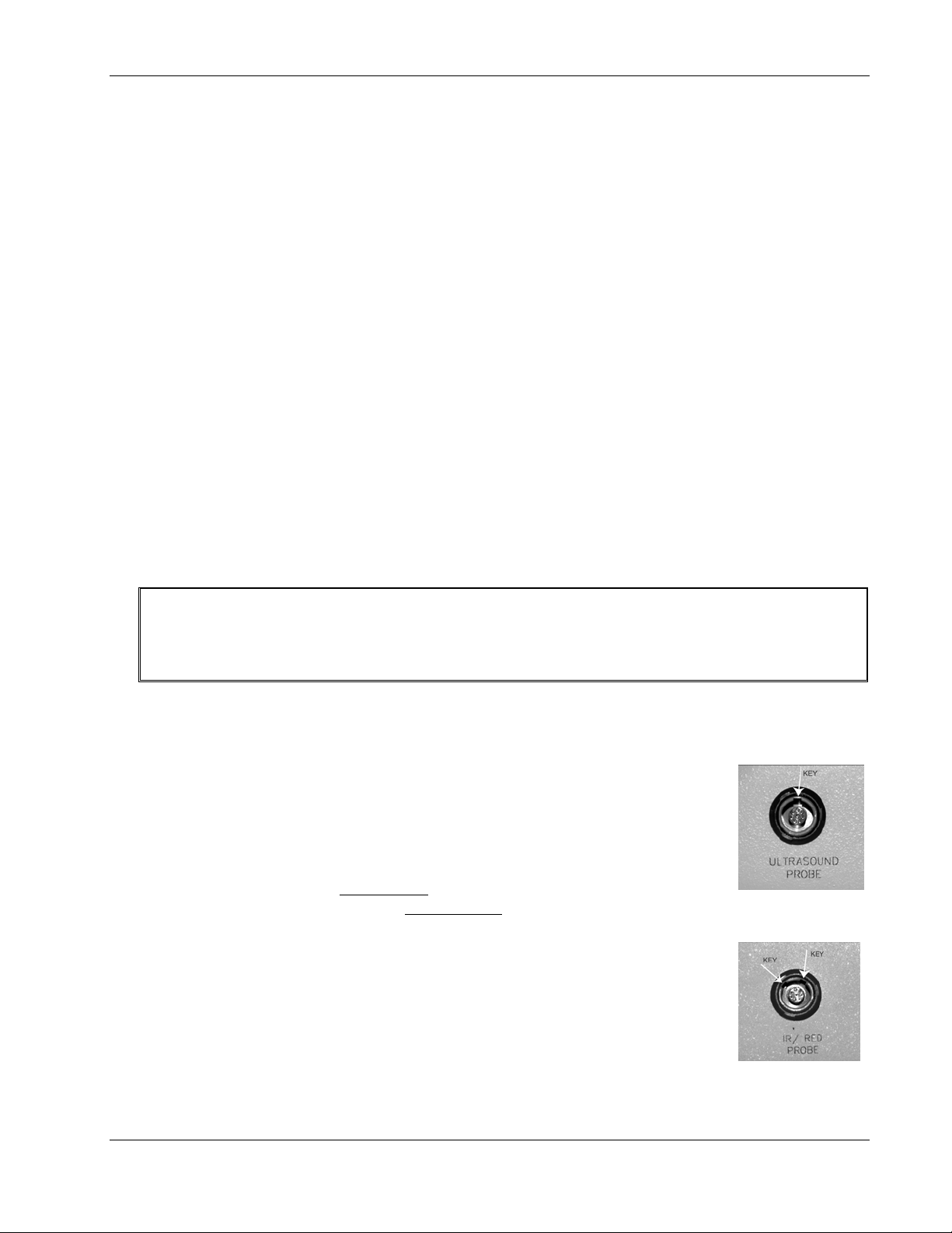
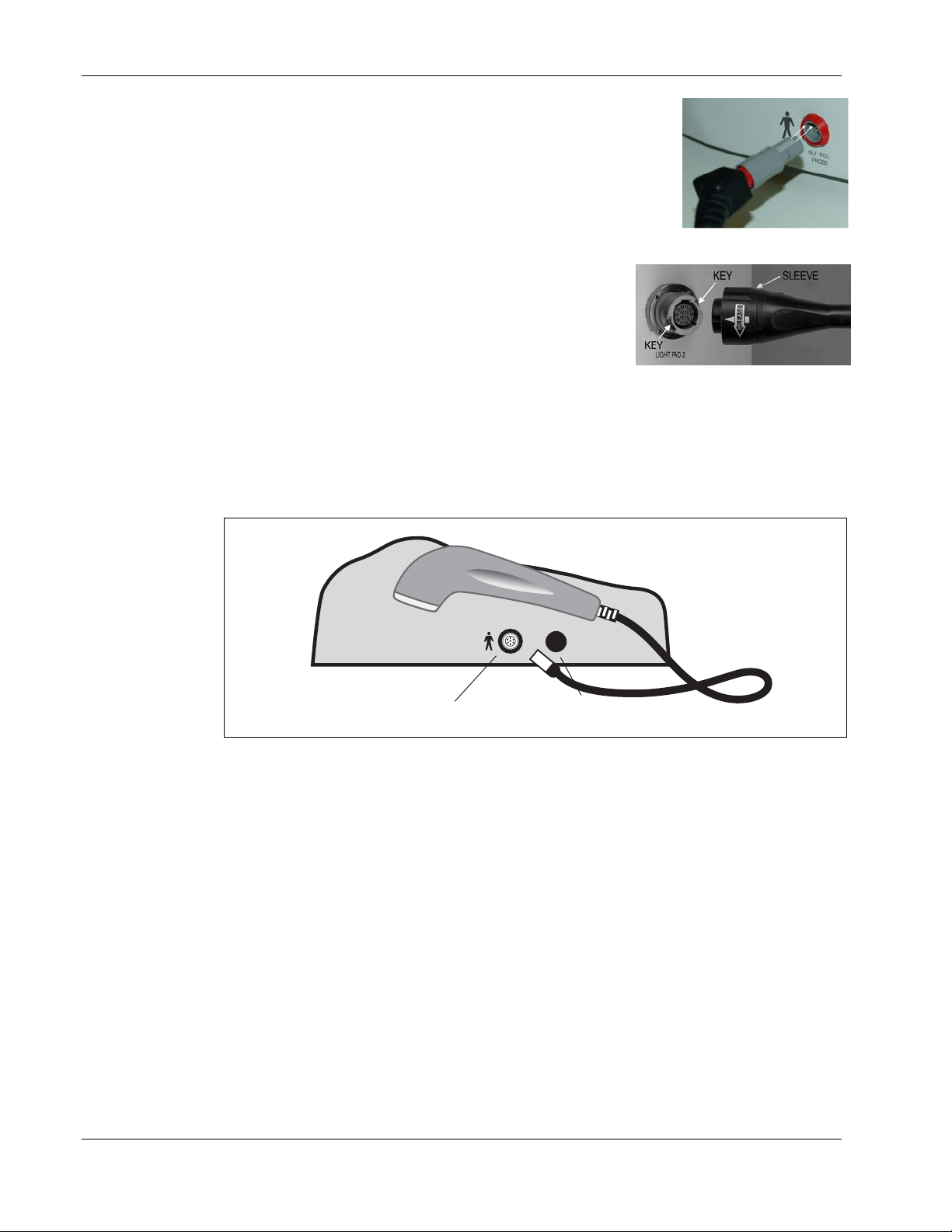
Output Connectors and Jacks
Connectors and jacks on the Solaris device are “Keyed/Locking”
connectors (see illustration to the right and on the following page). Use
caution when inserting the connectors into the output jacks. When the
keys are properly aligned, the connector and jack will slide together
smoothly and exactly. When removing the connector, the locking
mechanism is released when the outside connector shell is pulled away
from the device. Do not force
may occur. This damage is not covered
Note: Devices that have been custom ordered with the Patient
REMOTE STOP cable will have an additional jack located on the back
of the base unit. The remote stop is controlled by the patient during
unattended therapy to allow the patient to stop the treatment at any time.
When the button on the remote stop cable is pressed, output for all stim
modalities and pad treatments is stopped and the tone sounds briefly.
During Combo treatments, both sound and stim outputs are stopped.
the connector or damage to the pins
by warranty.
“Keyed” Ultrasound Jack
“Keyed” Probe Jack
19
Installation & Features
Dynatron Solaris® 700 Series
Keyed” Probe Connectors
When attaching the probe, align the raised portion of the connector
with the notched jack opening. When removing the
probe connector, the locking mechanism is released when the
outside connector shell is gently pulled away from the base unit.
“Keyed” Pad Connectors
The Pad connector is attached by aligning the connector
“Keyed” Probe Jack
with the keyed openings in the jack and pushing the
connector into the jack. To remove the connector, turn the
sleeve to the left in the direction of the “Release” arrow and
gently remove the connector. Do not use force when
attaching or removing the connector.
28. OUTPUT JACK CHANNELS 1, 2, 3, and 4
: These are
“Keyed” Pad Connector
the output jacks for delivering Interferential,
Premodulated, Russian, Biphasic, and Microcurrent treatments. These channels are
located in the front of the device. Front (left to right as you face the device).
29. HIGH VOLT OUTPUT JACK CHANNEL HV
. This is the output jack dedicated to
delivering High Volt pad treatments, located in front on the far right side.
Solaris Left Side View
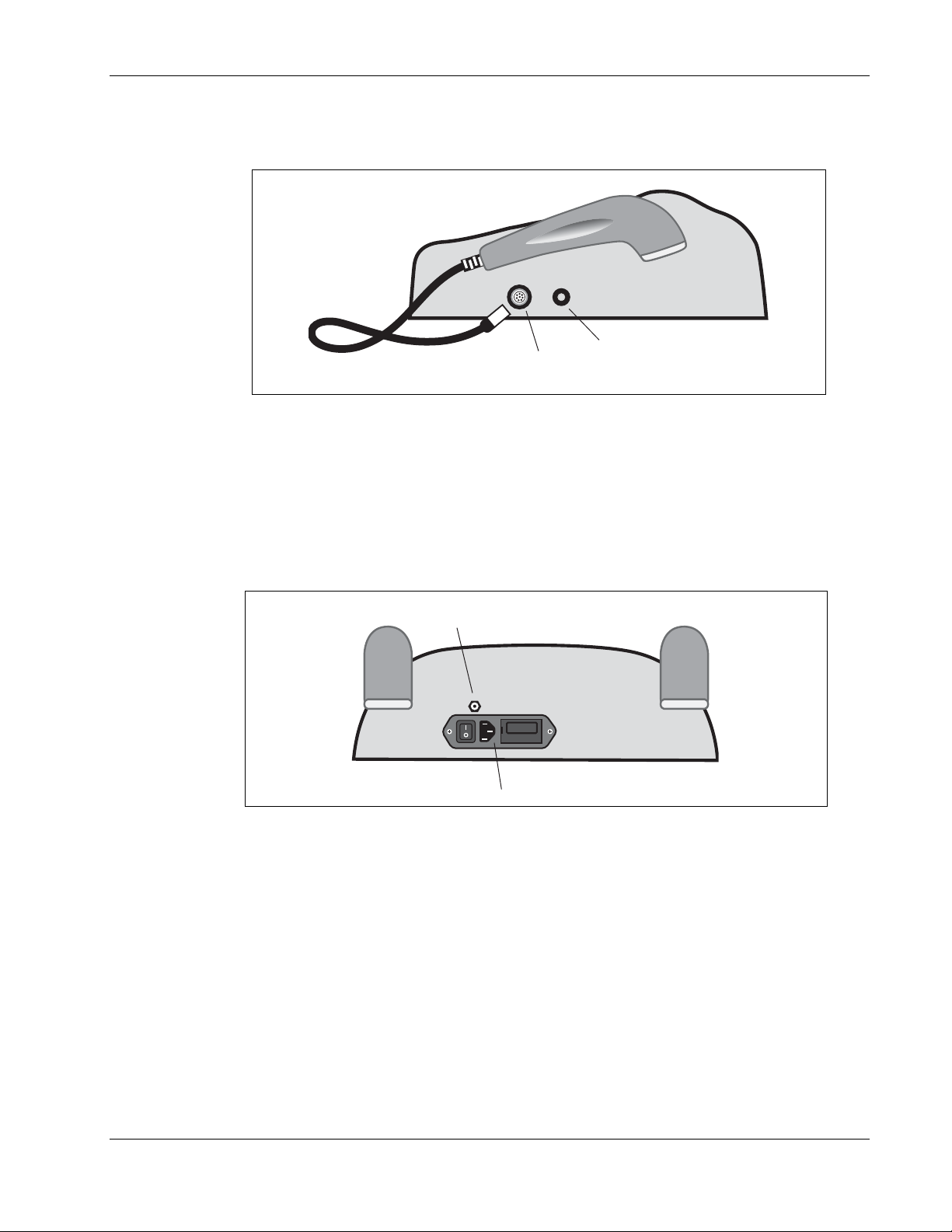
30. STIM PROBE JACK - MICROCURRENT/HV/DC PROBES TREATMENTS: The
universal MultiStim probe plugs into this jack for Microcurrent, High Volt or DC probe
therapy. After the probe is connected and either Microcurrent or High Volt keys have
been pressed, press the TIME TOGGLE key to select PROBE. If the Direct Current
modality is selected, the device will automatically default to PROBE. See illustration
above.
31. DYNATRON LIGHT THERAPY (IR/RED) OUTPUT JACK: This output jack is
designed to accommodate a single probe. When one of the Dynatron Solaris probes is
connected, the device will recognize the probe and will auto calculate time/dosage
(J/cm
32. COMBINATION TREATMENT JACK: The special combo lead wire for combination
treatments is plugged into this jack located on the right side of the device for a
combination treatment setup providing stim output through the Ultrasound head of the
D708, D709. For combination treatments using the D701, the Dynatron stim device is
plugged into the Combination Treatment Jack using a pin-to-banana adapter.
The special lead wire on the D708 and D709 is also plugged into the jack on the front of
Installation & Features
IR/Red Probe (31)
2
), Joules, and total treatment time. See illustration above.
20
Stim Probe (30)
Dynatron Solaris® 700 Series
the device which has been selected for the specific COMBO treatment. See combination
treatment instructions later in this manual for detailed information regarding combination
treatment setup. See illustration on the following page.
Solaris Right Side View
33. ULTRASOUND OUTPUT JACK (Ultrasound models only): The applicator soundhead
plugs into this jack for Ultrasound therapy. Located on the right side of the device. See
diagram on previous page.
Power Switch / Battery
34. POWER 1/0 (ON/OFF) SWITCH: Located on the back of the unit this switch is labeled
“1” and “0”. Set the switch to “1” for ON; set the switch to “0” for OFF.
battery (35)
Solaris Back Panel
35. BATTERY
: This jack may be used to supply power to the device using an optional
battery pack. More information about the optional battery operation is provided later in
this manual. (See illustration on the previous page).
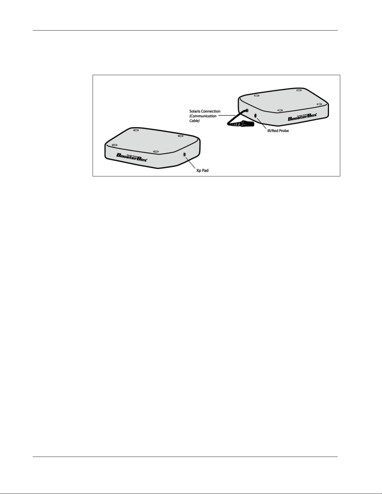
Booster Box / Booster Box Jacks
36. BOOSTER BOX / BOOSTER BOX JACKS (The Dynatron Booster Box is required for
use with the Dynatron Xp Pad on all Solaris 700 Series devices): The Dynatron Booster
Box is engineered to provide the additional power needed to operate the Dynatron Xp
Infrared Light pad. The Booster Box mirrors the outline of the outer-contours of the
Solaris console and stands approximately 2” in height. The flat upper surface of the
Booster Box is designed with four pre-molded circular receptacles at each corner in
which to place the rubber feet of the Solaris console, thus allowing the two units to fit
Ultrasound Probe (33)
power (34)
Combo Input (32)
21
Installation & Features
Dynatron Solaris® 700 Series
together with the appearance of a single device. The two units are electrically and
functionally connected by a communication cable (labeled SOLARIS CONNECTION)
attached to the Booster Box and designed to be plugged into the IR/RED output jack
located on the left side of the main Solaris console.
Booster Box and Jacks
The Booster Box has two output jacks: A LIGHT PROBE jack located on the left side
of the device in front of the communication cable and a LIGHT PAD output jack located
on the right side of the Booster Box. Please note: Only one Light Therapy treatment
(either probe or pad) may be given at a time.
Instructions for Using Toggle Keys
Toggle keys are used to make selections from two or more options in a given area. Toggle
keys are pressed one or more times to make a desired selection. A GREEN light (LED) next
to the toggle key shows the option that has been selected. Pressing the toggle key one or
more times allows you to scan through the available options.
Each toggle key has unique capabilities. Most toggle keys allow only one selection. For
example, the Ramp toggle key requires you to select just one of the four ramp times
available. However, some toggle keys allow you to select two options. For example, in
Interferential you can press the HIGH/LOW TOGGLE key once to select High, press again to
select Low, and press again to select both High and Low.
The following is a list of all the toggle keys available with each modality:
IFC and Premod
• Target/Sweep (IFC only)
• High/Low Frequency Ranges
Russian and Biphasic Stim
• Treatment mode
• Contraction/Rest cycle
• Ramp Time
High Volt Stim
• Contraction/Rest cycle
• Ramp Time
• Polarity
• High/Low Pulse Rate Ranges
• Channel toggle to select Pads/HV Channel or Probes Treatment (during setup only)
Installation & Features
22

Dynatron Solaris® 700 Series
Microcurrent
• Microcurrent Polarity
• Channel toggle to select Pads/Channel 1 or Probes Treatment (during setup only)
• Turn audible Conductance Tone ON/OFF
DC
• Polarity
Light Therapy
• CH Channel Toggle to select Pad or Probes Treatment
Ultrasound
• Ultrasound Frequency
• Ultrasound Duty Cycle
All Modalities
• Time/Frequency/Rate/Duration, etc., (only appropriate parameters for a given
modality are selectable)
• Channel Toggle (to view individual channels one at a time while treatments are in
progress)
Channel Output Indicator Lights
The TIME display and the
POWER INTENSITY display can
show the settings for only one
channel at a time. The Time and
Power-Intensity settings displayed
are for the channel with the
GREEN light only. Any other
channel in use at that time will
have a YELLOW light to show it
is active but its parameters are not
currently displayed.
To view the settings for another
channel or output, press the
channel toggle key one or more
times until the light for the
desired channel becomes
GREEN. The GREEN light appears next to a different channel or output each time you press
the toggle key, and the TIME and POWER/INTENSITY displays change to show the
parameters currently in effect for that channel. The GREEN and YELLOW channel lights
will also appear solid (non-flashing) or flashing. A solid light means therapy is being
delivered to the channel at this time (for example, during the ON cycle of the Russian
stimulation treatment). A flashing light means current is not being delivered to channel at
this time (for example, during the OFF cycle of the Russian stimulation treatment).
CHANNEL / OUTPUT INDICATOR LIGHTS
Channel Toggle Key
GREEN Solid • You CAN see this channel’s parameters displayed on Time
and Power-Intensity displays.
• The channel IS delivering current.
GREEN Flashing • You CAN see this channel’s parameters displayed on Time
and Power-Intensity displays.
• The channel IS NOT delivering current.
Installation & Features
23

YELLOW Solid • You CANNOT see this channel’s parameters displayed on
• The channel IS delivering current.
YELLOW Flashing • You CANNOT see this channel’s parameters displayed on
• The channel IS NOT delivering current.
Current Limit
The Dynatron Solaris devices continuously measure the actual current output during a
treatment and limit the output current to the level indicated in “Technical Information” in this
manual. As you increase the intensity of a treatment, you also increase current output. If you
reach the maximum current limit, the device issues a warning (described below). This
warning is to alert you to the fact that you may have set the treatment intensity too high and
to prevent the possibility of patient discomfort caused by too high current output.
Current Limit Warning
When you reach the maximum output current limit, the device will:
• Immediately stop increasing the intensity and automatically reduce the intensity a
few increments
• Beep several times
• Flash the intensity display
You should rarely, if ever, encounter the current limit warning during a patient treatment as
reaching the current limit would often require an intensity setting that is uncomfortable and
intolerable to most patients. For patient safety and comfort, you must address this warning
before continuing with the treatment. Consider the following possible causes, for example:
• The patient is unable to adequately feel the current and is unable, therefore, to report
discomfort at the high intensity level.
• When using four very large electrodes for a treatment, current is dispersed over a
larger electrode surface area permitting a higher intensity setting without discomfort to
the patient.
As you increase the intensity, ensure that the patient feels the current as expected. If the
patient is unable to feel the current, you could unintentionally raise the current to a
level much too high and risk causing unnecessary, possibly severe discomfort to the
patient. Keep the intensity very low if the patient has little or no feeling in the
treatment area (see “Contraindications, Warnings, and Precautions” in this manual).
Keep in mind, a wide range of factors can cause the patient to lack sufficient feeling in the
treatment area, including, but not limited to, pain control drugs, use of ice packs, neurological
damage, etc. Always consider these and other factors when delivering an electrotherapy
treatment, and determine intensity settings based upon your medical expertise and judgment.
If you encounter the Current Limit warning, it could indicate that the patient cannot adequately feel
the current. Ensure that the patient can feel the current. If you are treating an area that may be
desensitized for any reason, reduce the intensity immediately. Read all the warnings regarding
treatment of desensitized areas provided in this manual under “Contraindications, Warnings, and
Precautions.”
Dynatron Solaris® 700 Series
Time and Power-Intensity displays.
Time and Power-Intensity displays.
Installation & Features
24

Lead Wires / Electrodes
DID YOU KNOW?
Failure to replace worn lead wires and carbon electrodes or using cheap, poor quality
electrodes are some of the most common causes of patient discomfort.
• Lead wires should be replaced at least every six months.
• Carbon electrodes should be replaced approximately every six months
• Self-adhesive electrodes should be replaced after no more than 15 uses.
• You should never use monitoring electrodes
• Some brands of electrodes are of very poor quality or are inappropriate for electrotherapy.
Your patient may experience discomfort and even skin reaction due to poor distribution of
current when using these electrodes.
Lead Wires
Even with good care, lead wires will eventually develop breaks (open connections) simply
from normal usage, and they must be replaced. Lead wires have a limited lifetime and
must be replaced about every six months. Lead wires can be damaged due to jerking or
pulling on the wires; excessive bending or tight wrapping of the wires; or running over the
wire with a device cart. When setting up treatments, keep lead wires out of areas where a
person could trip on them. When storing, lead wires should be loosely wrapped to prevent
any kinking in the lead wire. Never use worn or damaged leads to treat a patient. Using
faulty leads may result in injury to a patient.
Test Leads Daily. Lead wires should be tested regularly to ensure they are functioning
properly and safely. A simple test performed with the Dynatron Solaris devices makes daily
lead testing convenient. Damaged or worn leads should be discarded and replaced. Under
normal use, leads should be replaced about every 6 months. Instructions for testing are
provided below.
Remove Corrosion From Lead Tips. Lead tips will build up corrosion through use. The
lead tips must be cleaned and kept free of this corrosion in order to function correctly. To
remove corrosion from lead tips, use steel wool to gently scrape off the corrosion. Take care
not to scratch the metal plating of the tip during cleaning. If the tip’s metal surface becomes
pitted or uneven, the lead must be replaced.
Test Leads
To test leads, perform the following steps daily. Begin with the machine turned off.
1. Press and hold the TARGET/SWEEP toggle key while turning the device on. After
initial power up, the Lead Test function is launched. If the device is already powered on,
you can enter the Lead Test function by pressing and holding the FUNCTION key while
pressing the TARGET/SWEEP toggle key. When the device is in the Lead Test mode,
the Time display will read “LEAD.”
2. Plug a lead into Channel 1 (no other channel is used for the lead test). Remove snap
adapters (if applicable) from the leads. UNDER NO CIRCUMSTANCES SHOULD
THE LEADS BE CONNECTED TO A PATIENT DURING THIS TEST!
3. Press START. A tone will sound. Hold the tips (pins) together. The tone will stop if the
leads are functioning properly.
Dynatron Solaris® 700 Series
.
nor ordinary TENS electrodes with this device.
25
Installation & Features
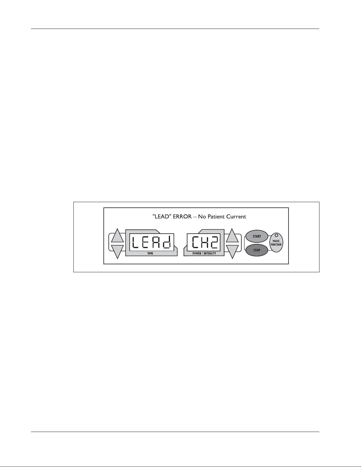
Dynatron Solaris® 700 Series
4. Hold the pins securely together, move the leads around, wiggle the cord, especially
at the jack end of the cord. If the tone sounds, even for a short time, check to be sure
you are holding the pins together. If the tone continues to sound and you are certain the
pins are touching, the leads are probably bad and should be replaced.
5. After the test, remove the lead from Channel 1. Plug in the next lead to be tested, and
continue testing all leads in this way.
6. To exit the Lead Test function, press STOP. The device then shows the normal treatment
displays, and you may proceed with treatment setup.
NOTE: The Lead Test should be used for testing patient lead wires only. This is not an
accurate means of testing carbon electrodes. Contact Dynatronics Customer Service to
arrange for free testing of carbon electrodes or for instructions for testing these electrodes.
“LEAD” Warning - No Patient Current
This added safety feature warns you if the device detects an “open” or incomplete circuit
during setup of an Interferential treatment. An “open” or incomplete circuit can be due to a
lead that is not plugged in, an electrode that has fallen off or otherwise is not making contact
with the patient, or any reason that would cause an incomplete circuit. When this occurs,
current is not being delivered to the patient, and the condition must be corrected before
continuing with treatment setup.
No Patient Current: During an Interferential treatment setup, if an “open” is detected, the “Lead”
warning is displayed along with the channel number that triggered the error.
When the device detects this condition during the treatment setup, it will beep and display
“LEAD” in the Time display. It will indicate in the Intensity display the number of the
channel that has triggered the error (for example, CH2) and will prevent you from increasing
the intensity setting. If this error occurs, reduce the intensity for the channel indicated,
correct the condition, then return the intensity to the desired treatment level. In adjusting
intensity, always observe the warnings and precautions provided in the operator’s manual for
this device.
This error will not be detected if the intensity is set below 11. The error condition can also be
detected during setup of Premodulated treatments at the High frequency settings only.
The error warning will also occur while a treatment is in progress under the same conditions
described above, but will only be displayed if the affected channel is currently selected for
display.
Disable the Lead Warning: If you find the lead warning feature is too sensitive for your
treatment setup and is detecting conditions that are not truly open, you can adjust the
sensitivity. To do this, press and hold the IFC key while powering the device on (NEVER
TURN THE DEVICE ON OR OFF WHILE LEADS ARE CONNECTED TO A
PATIENT). The word “OPEN” is displayed in the Time display, and the default setting of
Installation & Features
26

24 is displayed in the Intensity display. A lower number provides reduced sensitivity. At a
zero setting no error will be displayed. Use the up/down arrow keys to change the setting,
then press Start to exit this mode. The setting you select will remain as the default for the
device until you change it.
Carbon Electrodes
Carbon electrodes provide an economical means of delivering electrotherapy to patients but
should not be used with Microcurrent. This type of electrode lasts a long time and can be
used again and again. However, if they are not properly cared for, these electrodes can fail to
deliver the desired treatment and can present the possibility for injury to a patient.
To ensure greatest safety and effectiveness with your treatments, follow these rules when
using carbon electrodes.
1. Carbon electrodes must be well-moistened prior to treatment setup. Dry carbon
electrodes are very poor conductors of current and should NEVER be used. They may be
moistened with either water or an electrolyte spray. Water is adequate for short
treatments, but will evaporate too quickly for longer treatments. If water is used for
longer treatments, you may need to interrupt the treatment and remoisten the electrodes.
A special sponge fabric available with some carbon electrodes may be moistened well
and used as a conductive medium (do not use ordinary sponges for this purpose). Do not
use Ultrasound gel as a conductive agent with carbon electrodes.
If you use an electrolyte spray, this liquid may be diluted with equal amounts of distilled
water, if desired. This reduces the amount of build-up on the electrodes yet usually
provides adequate moistening of the electrodes.
NOTE: As you increase the intensity to higher levels during setup, if your patient feels a
“biting” sensation or if the patient feels nothing, this indicates you are not getting
adequate conductivity—the electrode may be too dry or is not moistened evenly across its
entire surface. Stop the setup and correct the problem.
2. Carbon electrodes must be free from any build-up. If electrodes have a build-up from
body oils or a moistening agent such as an electrolyte spray, conductivity is greatly
impaired. If treatment is allowed to continue, intensity could be inhibited. When using
carbon electrodes with any electrotherapy device, you must make sure conductivity is not
impaired due to any type of build-up on the electrodes.
3. How to Clean Carbon Electrodes. Carbon electrodes from Dynatronics may be cleaned
using a mild soap and a small brush (such as a nail brush). To sterilize, alcohol may be
used. They may also be sterilized in an Autoclave. Daily cleaning is recommended.
4. Carbon electrodes eventually wear out. Do not assume you can safely use carbon
electrodes indefinitely. Over time these electrodes will wear; and when worn, the amount
of current delivered through the electrode will decrease and will be inconsistent over the
surface of the electrode. As a general rule, carbon electrodes that are used regularly
should be replaced at least every six months.
If you think your carbon electrodes are showing wear, you can send them to Dynatronics
to be tested with an ohm meter. Good carbon electrodes should test at between 40 and
200 ohms. Unfortunately, practitioners frequently send us electrodes having resistance
measuring in the thousands of ohms! Overused electrodes such as this present a potential
hazard to the patient.
Dynatron Solaris® 700 Series
Do not take chances with patient safety!
Discard worn carbon electrodes!
27
Installation & Features

Self-Adhesive Electrodes
Dynatronics’ self-adhesive electrodes are intended for multiple but patient specific use due to
the danger of cross contamination. Improper use of the electrodes can decrease the life of the
electrode and could even result in harm to your patient. The following instructions will help
you achieve maximum usage from your electrodes while ensuring patient safety and comfort
during treatment.
1. Make sure the electrode is adhering and making contact with the skin across the
entire surface of the electrode. Electrodes will lose their adhesive quality when
exposed to air, dust, dry skin, etc.
To Retain Adhesiveness:
• Electrodes should be stored in a tightly sealed pouch until used.
• The patient’s skin should be thoroughly cleaned and free from oils or flakiness prior
• Before a Treatment: Before placing the electrode on the patient, moisten the patient’s skin
• After a Treatment: Spray the adhesive side of the electrode with plain water, rub it
2. NEVER use a self-adhesive electrode for more than 15 treatments (maximum).
3. NEVER use STRAPS, weights, or other devices to attach self-adhesive electrodes to
4. Never use monitoring electrodes such as ECG, or EMG, nor ordinary TENS
5. If you see the “No Patient Current” screen message, or if you observe poor conductivity
to placing the electrodes.
To Restore Adhesiveness:
with a damp cloth using plain water, then apply the electrode to the skin.
lightly with fingertips, then reapply the electrode to its plastic backing and seal it tightly
in its storage pouch. Do not use an electrolyte spray to remoisten self-adhesive
electrodes
as this substance can destroy the adhesive. Self-adhesive electrodes do not
require sterilization.
With this method of re-hydration, after a couple of hours electrodes can regain up to
90 per cent of their original adhesive quality.
the skin. If an electrode has lost its adhesive quality, you can use one of the methods
given above to re-hydrate the adhesive, or you should discard the electrode. Using
straps and weights with self-adhesive electrodes could have an unpredictable effect
on the electrodes and could cause injury.
electrodes.
indicators, check the electrodes and lead wires for proper connection.
Dynatron Solaris® 700 Series
Installation & Features
28

Dynatron Solaris® 700 Series
Quick Reference of Special Key Presses
The following is a brief list of special key presses available with this device. These options are explained in
detail where they apply in the treatment instructions later in this manual. NOTE: Where two keys are
required (i.e., FUNCTION-STOP) you must press FUNCTION immediately followed by STOP to achieve the
result.
KEY PRESS RESULT DESCRIPTION
FUNCTION-STOP STOP TREATMENT
FUNCTION-HI VOLT
FUNCTION-SOUND HEAD WARMING ON/OFF Set head warming feature to on (HD 1) or off (HD 0)
FUNCTION DISPLAY WATTS or W/cm2
CHANGE HIGH VOLT
POLARITY
Stop one treatment. Active treatment indicated by lighted
LED will be stopped.
Change High Volt polarity. Repeat to change again.
During Ultrasound treatment, hold for 2 seconds to change
Ultrasound power display from w/cm
2
to Watts or reverse.
FUNCTION-TIME
TOGGLE
FUNCTION-TIME
TOGGLE
FUNCTIONTARGET/SWEEP KEY TEST LEADS
FUNCTION-MICRO
MICRO AUDIO TONE ON/OFF During a Microcurrent treatment, turn audio tone on and off.
FUNCTION –
DIRECT CURRENT
FUNCTION-
INTENSITY UP &
DOWN ARROW KEYS
START
FUNCTIONINTENSITY DOWN
ARROW
DISPLAY JOULES or J/cm2
TURNS OFF MICROCURRENT
CONDUCTANCE BAR
CHANGE MICROCURRENT
POLARITY
CHANGE DIRECT CURRENT
POLARITY
CHANGE VOLUME
SAVE NEW DEFAULT
SETTINGS
DISABLE ULTRASOUND
COUPLING DETECTION
During Light Therapy Probe/Pad treatment, press FunctionTime Toggle to change the Light Therapy power display from
2
J/cm
to Joules or reverse.
During a Microcurrent treatment, press the Function-Time
Toggle to turn off the Conductance Bar.
Enter the Lead Test Function. Then press START to begin
lead test, and press STOP to exit the lead test function.
NEVER DO THIS WHILE ELECTRODES ARE ATTACHED
TO PATIENT.
Change Microcurrent polarity. Repeat to change again.
Change Direct Current polarity. Repeat to change again.
Change loudness of tone (during Microcurrent treatment
only)
Hold for 2 seconds to save defaults for current treatment.
In Ultrasound mode, press and hold these keys to disable the
Ultrasound coupling detection feature. The Time display will
show the current setting briefly: CP1=feature on,
CP0=feature off. Repeat this step to revert to the prior
setting.
AT POWER ON, HOLD DOWN THE FOLLOWING KEYS WHILE THE DEVICE STARTS UP:
KEY PRESS RESULT DESCRIPTION
TARGET/SWEEP LEAD TEST MODE Press and hold on power up to enter Lead Test feature.
START
RESTORE FACTORY
SETTINGS
Press and hold on power up and wait for beep to restore
factory default settings.
29
Installation & Features

Dynatron Solaris® 700 Series
Installation & Features
30

Dynatron Solaris® 700 Series
SECTION II
OPERATION AND TREATMENT
INSTRUCTIONS
31
Operation & Treatment Instructions

Dynatron Solaris® 700 Series
Electrotherapy Information
and Usage Cautions
The following are general cautions are to be observed during Interferential, Premodulated, Russian,
Biphasic, High Voltage, and Direct Current stimulation. For Microcurrent electrotherapy, see
additional cautions in the Microcurrent Section of this manual.
• NEVER turn the power ON or OFF while the unit is connected to the patient.
• Always STOP a treatment before removing or attaching electrodes or leads. Leads and
electrodes must only be applied to the patient before a treatment is started.
• Never use worn or damaged leads or electrodes as these may result in injury to the patient.
• If using a Remote Stop cable, always give the cable to the patient prior to the treatment.
• See the contraindications, warnings, and precautions for Interferential and Premodulated
treatments in this manual before administering a treatment to a patient.
• Additional warning from the Canadian Health and Welfare Department, Health Protection
Branch: WARNING: Thoracic applications are contraindicated. Cardiac fibrillation may
occur if output current is 50 mA RMS or greater for any output circuit. (For use in Canada
and Japan, this device is limited to 50mA output.)
Electrical stimulation, by its very nature, has the ability to irritate the patient’s skin. Certain
precautions should be observed to assure maximum safety and comfort for patients. A
patient’s tendency to have adverse reactions is dependent upon several factors. These factors
WARNING
are:
Current Density. This is the amount of current being delivered to the patient divided by the
area through which the current is being delivered (the surface area of the electrodes being
used).
Electrode Condition. Worn or dried out electrodes cause the current to concentrate in small
areas of the electrode instead being evenly distributed over the entire surface of the electrode.
This has the effect of concentrating and increasing the current density into small areas.
Patient Susceptibility. Some patients’ skin is more sensitive to electrotherapy currents.
This can cause a reaction similar to a heat rash.
Electrotherapy treatment can result in a rash, burn, or blister. The tendency to do this is
dependent upon the factors listed above and can be minimized by applying the following
guidelines:
1. Use only moderate current. It is not always necessary to raise the treatment intensity to
just short of the patient’s pain threshold to achieve adequate results. Suggested
maximum treatment levels for different electrode sizes are given below (for
Operation & Treatment Instructions
32

Dynatron Solaris® 700 Series
Interferential or Premodulated therapy). These values are not intended to be inflexible,
but they should be a guideline. If your treatment goes beyond these intensities, you
should examine the treatment to discover why such a high intensity setting is required.
Use as large an electrode as is practical for the application. Note that the current density in a
1.25” square electrode is over FOUR TIMES the current density in a 1.75” by 3.75”
electrode for the same intensity setting. Using larger electrodes allows current to be
delivered over a larger area of the body keeping the current density as low as possible and
minimizing the possibility for adverse reactions.
On the following page is a chart comparing the size of the self-adhesive and carbon
electrodes with their suggested maximum intensity levels. NOTE: The intensity settings
should be considered maximum
and not target intensities. These suggested settings apply
to Interferential and Premodulated treatments. For High Voltage pulsed stimulation the
intensity is displayed in volts; therefore, these suggested settings do not apply. For
Biphasic or Russian stimulation treatments intended to effect a muscle contraction, it may
sometimes be necessary to exceed these recommended limits to achieve the desired
results. However, use caution when doing so to ensure that the patient can feel and can
comfortably tolerate the electrical current. Also observe all other precautions in this
section concerning leads and electrodes to ensure the higher intensity setting is not
necessary as a result of defective accessories. In any case, do not exceed patient
tolerance in setting the intensity. Consult published medical literature for more
information about treatment protocols using each of these electrotherapy modalities.
Interferential / Premodulated
Electrode Size
Carbon Electrodes 3” round 25-30
3” x 5” 30-40
Self-adhesive Electrodes 1.75” square 10-15
1.75” x 3.75” 25-30
1.25” round 10-12
2” round 10-20
3” round 25-30
Combination Treatment Usage Cautions
Maximum Recommended Intensity
When delivering combination Ultrasound and stim treatments where the stim current is
delivered through the soundhead, the following are the recommended maximum stim
intensities (refers to Premodulated, Biphasic or Russian stimulation only):
Maximum Recommended Intensity
Head Size for Electrotherapy
2
2cm
5cm
10cm
head: 4-7
2
head: 10-15
2
head: 15-20
2. Ensure that the area on the patient’s skin where the electrode is to be placed is clean and
free of all foreign matter. This includes powders, perfumes, and the like, as well as body
oils or dirt and grime. Cleaning with an alcohol wipe should be adequate. Allow the
alcohol to fully evaporate before applying the electrodes.
Iontophoresis occurs with all electrical current therapies and can drive any of the above-
surface contaminants below the epidural layer where an allergic reaction may occur.
3. Make sure the electrodes being used are in good condition. The poly adhesive electrodes
should have good adhesion over the entire surface area of the electrode. The area where
33
Operation & Treatment Instructions

Dynatron Solaris® 700 Series
the leads attach to the electrode (either through a lead or a snap) should not be damaged
such that the connection to the foil backing behind the adhesive is broken. Carbon
electrodes should be deep black, and should be free of cracks in the electrode surface.
Any electrode which is suspect should be discarded—it’s not worth
the price of an electrode to risk harming a patient.
4. Some patients tend to be much more sensitive to electrotherapy treatments. On patients
with this tendency, treat with reduced intensity and/or shorter treatment times, with
possibly more frequent treatments, if required. Most reactions are localized and very
short-lived, so limiting the exposure should minimize any potential for adverse reactions.
Operation & Treatment Instructions
34

Dynatron Solaris® 700 Series
Interferential / Premodulated Instructions
An Interferential treatment uses two channels and four electrodes (channel pairs 1-2 or 3-4). The device will
automatically select the first available channel pair when you select IFC. A Premodulated treatment uses one
channel and two electrodes. The device will automatically select the first available channel (1, 2, 3, or 4)
when you select PREMOD. If desired, you may set up multiple treatments using available channels. Please
note, channels 3-4 are only available on Solaris 706 and 709.
Basic Interferential / Premod Setup
1. Choose IFC or PREMOD.
• Plug the patient lead(s) into the output jack(s) for the channel(s) selected.
• Attach electrodes to patient at treatment site.
2. Set the treatment TIME.
3. (Optional) CUSTOMIZE FREQUENCIES now.
4. Choose HIGH, LOW, or HIGH/LOW alternating, or HIGH/LOW consecutive using
the HIGH/LOW TOGGLE key.
5. Choose TARGET, SWEEP or STATIC (for Interferential treatments only) using the
6. Increase INTENSITY (patient will feel the current) using the POWER/INTENSITY
ARROW keys.
7. If TARGET is selected, use the target pad to focus therapeutic beat to desired site.
8. Press START
9. Press STOP if you need to stop a treatment before its time has expired (stops all currently
Detailed Interferential / Premodulated Setup
TARGET SWEEP TOGGLE key.
active treatments). Use the TIME arrow keys to bring treatment time to zero or press the
FUNCTION key and immediately followed by the STOP KEY to stop only the individual
displayed treatment.
NOTE: Prior to increasing intensity, electrodes must be placed on the patient and the lead(s)
attached to the device. Plug the lead(s) into the channel(s) the device selects for this
treatment. Consult published sources for electrode placements, treatment settings, and
treatment times. Make sure electrodes make good contact with the patient’s skin over the
entire surface area of the electrode. Improper electrode contact may result in patient injury.
1. Press the IFC / PREMOD key once to choose IFC (Interferential), or press this key
twice to choose PREMOD (Premodulated).
When you choose IFC, channels 1-2 or 3-4 are automatically selected. When you choose
PREMOD, the first available channel is selected. Make sure the patient lead is plugged
into the correct jack(s) for the channel(s) selected. The default settings for the modality
are automatically selected too, and if you wish to use the default settings, you can now
increase the intensity to the desired level, then press START.
35
Treatment Instructions - IFC & PREMOD

Dynatron Solaris® 700 Series
If you wish to change the treatment settings, proceed through the following steps.
2. Set TIME.
The default treatment time is displayed. Use the TIME arrow keys to increase or
decrease the treatment time.
3. Customize the FREQUENCY settings (optional).
The default High and Low frequency settings are:
HIGH range is 80 to 150 Hz.
LOW range is 0 to 10 Hz.
These ranges may be changed for a single treatment if desired, or new default
settings may also be saved to apply to all future treatment setups. The same default
setting applies to both Interferential and Premodulated treatments.
You may change the frequency settings for the range you plan to select for this treatment,
if desired (see illustration next page). Each Interferential or Premodulated treatment may
have its own frequency settings. After you press START to begin the treatment,
frequency settings will remain in effect for the duration of the treatment. If you save
defaults during this treatment, the new frequency settings you have entered become the
defaults for this modality. However, if you do not save the new settings, the unit will
return to the current default settings for the next treatment.
To modify the frequency during setup, first, press the HIGH/LOW TOGGLE key and
select either the HIGH or the LOW frequency range. Next press the TIME TOGGLE key
to select FREQ (Frequency) as the parameter you wish to change. The LED next to
FREQ will be lighted. The current frequency range settings will be displayed in the
TIME and POWER.INTENSITY displays as shown in the diagram on the following
page. With FREQ selected and either the HIGH or LOW range selected, you may use the
TIME and POWER/INTENSITY UP/DOWN ARROW keys to change the upper and
lower limits of the frequency range chosen. If you set both displays to the same value,
the treatment will be delivered at that single frequency rather than sweep through a
frequency range.
When you are finished setting the frequencies, press the Time toggle key to return to the
Time display. After 10 seconds with no key presses, the Time display automatically
returns.
4. Choose HIGH, LOW, HIGH/LOW alternating, or HIGH/LOW consecutive.
Press the HIGH/LOW TOGGLE key one or more times to select the high frequency
range, the low frequency range, or both. The lights next to the toggle key show what you
have selected. Select from the following options:
a. High only. Toggle until only the High light is on.
b. Low only. Toggle until only the Low light is on.
c. High/Low Alternating. Toggle until both High and Low lights are on, only one of
these is flashing. When the treatment has started, the device alternates between the
two modes at intervals of approximately 30 seconds each beginning with Low.
d. High/Low Consecutive. Toggle again so that both High and Low are flashing.
During the first half of the treatment time the High frequency range is delivered.
During the second half of the treatment time the Low frequency range is delivered.
IFC & PREMOD - Treatment Instructions
36
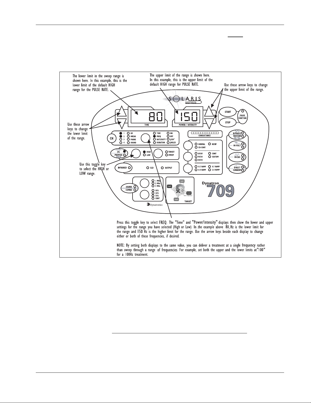
Dynatron Solaris® 700 Series
NOTE: Make any desired changes to the treatment time before selecting
Consecutive. Treatment time changes made after selecting Consecutive will cause
the treatment to revert to an alternating treatment (option “c”. above).
Once the treatment has started, the frequency range (High or Low) being delivered at a
given time is indicated by the flashing High or Low light.
Modify frequency ranges in Interferential or Premodulated treatments
5. Increase INTENSITY.
Set the intensity by pressing the POWER/INTENSITY UP arrow key. When you
increase intensity, current to the patient begins. Intensity can be decreased by pressing
the DOWN arrow key. NOTE: The CONDUCTANCE BAR GRAPH will be operable at
this time.
Before selecting the intensity setting for an individual patient, see “Electrotherapy
Information and Usage Cautions” in this manual for recommended intensity settings.
Also see the section of this manual entitled “Contraindications, Warnings, and
Precautions” for specific precautions when treating any conditions contributing to loss of
sensation, or any time the patient cannot feel the electrical stimulation
6. Choose TARGET, SWEEP, or STATIC (for Interferential only).
TARGET. Press the TARGET/SWEEP TOGGLE key to select this option if it is not
already selected. The Target feature allows you to pinpoint the treatment site to deliver
the full Interferential current where it is needed.
Treatment Instructions - IFC & PREMOD
37
.

Dynatron Solaris® 700 Series
NOTE: You must set the intensity before using the Target Pad so the patient will
be able to tell you when the treatment site is found. Also remember, an injured area
will often be more sensitive to the current delivered. Therefore, an intensity setting that
is comfortable to the patient at first may feel uncomfortable when the treatment site is
found using the TARGET PAD. If necessary, reduce the intensity to the patient’s
comfort level.
SWEEP. Press the TARGET/SWEEP TOGGLE key one or more times to select this
option. This option uses Dynatronics’ Target feature to automatically move the point of
interference in a somewhat spiral fashion covering 75 to 80 percent of the area within the
electrodes. This allows you to bathe a more general area with the Interferential current
while retaining the full Interferential beat.
STATIC. This option is applied when neither Target nor Sweep are selected. Press the
TARGET/SWEEP TOGGLE key one or more times to unselect the Target and Sweep
options (the LEDs will both be off). The treatment becomes a STATIC treatment. In other
words, it simply allows the two currents to take a path of least resistance and intersect at a
natural point within the electrodes.
7. Press START
When you press start, the treatment timer in the TIME display window begins counting
down and the treatment proceeds. If you fail to set the intensity before pressing START,
the intensity display will begin flashing, and you will be unable to start the treatment
until you set the intensity.
SAVE DEFAULTS. If the treatment you have just set up is a frequently used treatment
setup, you can save the treatment parameters as new defaults for your own machine.
After setting up the treatment, simply press and hold the START key until you hear a
beep indicating the treatment parameters have been saved. The next time you select that
modality, these parameters are selected automatically.
8. MODIFY settings.
While the treatment is in progress, you can modify any of the treatment parameters, if
desired. Note: If you change the treatment time during a CONSECUTIVE High/Low
treatment, the treatment will revert to ALTERNATING High/Low.
• Use the HIGH/LOW TOGGLE key to select a different frequency option (High,
Low, or High/Low alternating only. High/Low consecutive is only available
during treatment setup).
• Use the TARGET/SWEEP TOGGLE key to change this option (IFC only)
• Use the TIME ARROW keys to increase or decrease the treatment time.
• Use the POWER/INTENSITY ARROW keys to increase or decrease the
intensity.
• Relocate the treatment site by touching the TARGET PAD at any time during the
treatment (only when TARGET is selected).
9. Press STOP if it is necessary to stop a treatment before time has expired.
When the treatment time has elapsed, the current to the patient stops and a tone sounds
notifying you of the treatment end. Treatments in progress may be stopped at any time
using one of the following methods.
STOP: Press this key to stop all treatments at all channels.
IFC & PREMOD - Treatment Instructions
38

Dynatron Solaris® 700 Series
STOP ONE TREATMENT ONLY: If you have more than one treatment in progress,
you can stop one treatment by either of the following methods. First, press the
CHANNEL TOGGLE key to select the channel to be stopped (that channel’s light is
GREEN when selected).
FUNCTION-STOP. Press and hold the FUNCTION key and press STOP.
REDUCE THE TREATMENT TIME TO ZERO. Press the Time down arrow
until the Time display reaches zero. The device beeps when the time reaches
zero.
The output at the selected channel is stopped, and the device then displays the parameters
for the next treatment that remains in progress (if there is an active treatment).
39
Treatment Instructions - IFC & PREMOD

Dynatron Solaris® 700 Series
Interferential and Premodulated
Modality Information
Interferential (Quadpolar) Therapy
Interferential therapy uses four electrodes to
deliver two currents, one current with a
constant frequency of 4000 Hz and the other
current with a variable frequency of 4000 to
4150 Hz. The paths of these two currents
cross resulting in a “beat” that produces the
therapeutic frequency at the treatment site.
The resulting frequency is between 1 and 150
Hz. An example of wave forms representing
these currents is illustrated here.
Stimulation produced by 4 electrodes.
Premodulated (Bipolar) Therapy
Premodulated therapy utilizes one output jack and two electrodes. The current delivered is a
composite wave form. In order to produce this composite current, two frequencies are
“mixed” within the device prior to output. One frequency is 4000 Hz while the second
frequency covers a range between 4000 to 4150 Hz.
With the Dynatron Solaris devices, any of the four channels may be used simultaneously to
deliver up to four separate, independent Premodulated treatments. A crisscross electrode
setup pattern should not
that a Premodulated treatment usually requires a lower intensity setting than an Interferential
treatment since current is dispersed to only two electrodes rather than four (a smaller total
coverage area means greater current density at the treatment site).
In the Interferential
mode, two output
jacks (Channels 1
and 2, or 3 and 4)
are utilized with
four electrodes placed in a crisscross fashion, “bracketing” the
treatment site as shown in the illustration to the left. The output
from Channel 1 (or Channel 3) is the constant 4000 Hz wave,
while the output of Channel 2 (or Channel 4) is the variable 4000
to 4150 sine wave.
be used when setting up multiple Premodulated treatments. Note
The “beat” phenomenon. Two waves of
different frequencies over 4000 Hz, combine to
produce a beat which is between 1 and 150 Hz.
IFC & PREMOD - Treatment Instructions
40

Target
The Dynatron Solaris Series devices feature Dynatronics’ TARGET feature (available for
Interferential treatments only) that simplifies electrode placement for an Interferential
treatment. Interferential treatment is performed using four electrodes with two channels.
The channels produce two currents which intersect producing the Interferential “beat.” Without
Target, it is often difficult to place the electrodes in the right position to produce the beat at the
desired treatment area. This is because different types of human tissue (skin, muscle, bone,
etc.) conduct current differently, making it impossible to guess the course of the two currents.
Target helps eliminate the need to move the electrodes to achieve the desired result.
With Dynatronics’
Target feature, you
can move the center of
interference (where
the two currents cross)
simply by moving
your finger across the
Target touch pad.
Patient feedback will
let you know when
you have positioned
the treatment at the
desired spot.
In the diagram the
electrodes are placed in a position to treat a point directly in the center of the electrodes. But
the center of interference actually occurs at another point. (In these illustrations the point of
interference is shown in a cloverleaf shape as Interferential treatment affects a cloverleafshaped area.) Using the Target pad, the point of interference in easily moved to the desired
treatment area.
Why Is Target Better?
The Dynatron Solaris devices employ a
unique, method which actually moves the
center of interference. With Target, the
voltage output from both channels remains
equal at all times; so wherever the treatment is
applied, a full, deep Interferential beat occurs.
Other devices attempt to achieve this effect by
increasing the current from one channel while
decreasing the current from the other channel.
This method only rotates the cloverleafshaped area, but the center of interference
does not move. In addition, the depth of the
beat is reduced.
Target Sweep
You can use the Sweep (Target Sweep) feature
to bathe a wider area with the Interferential current—up to 80 percent of the area within the
electrodes may be covered. The Sweep feature utilizes the Target feature and moves the
Dynatron Solaris® 700 Series
Normal Interferential currents cross at a point between electrodes. It is
difficult to guess where they will cross as shown in the left diagram. With
Target, you move the point of interference without moving electrodes (as
shown in the diagram on the right)—just press the touch pad.
Other devices increase current at one
channel while decreasing it at the other.
This merely rotates the treatment. The
center of interference does not move.
41
Treatment Instructions - IFC & PREMOD

Dynatron Solaris® 700 Series
point of interference to cover a wider treatment area while still retaining the full Interferential
beat.
The Sweep option literally moves the
point of interference inward and outward
in a somewhat spiral pattern as shown in
the illustration to the right, bathing about
80 percent of the area within the
electrodes with the Interferential current.
Interferential Electrode Placement
When performing Interferential therapy
with a two-channel/four-electrode setup,
it is important to arrange the electrodes in
a crisscross manner so the current from
one channel will intersect with the current
from the second channel at the point
where treatment is to be delivered.
Consult published literature for electrode
placements for specific sites and
conditions.
Interferential / Premodulated Default
Settings
Interferential Default Settings
The following default settings are set by
the manufacturer and are selected when
you select IFC or PREMOD. You
may change these defaults to your
own preferred settings.
• High
• Target
• The first available channel pair (1-2
or 3-4)
• Time: 10 minutes
• Frequency Ranges (for both
Interferential and Premodulated)
Default High Range: 80-150 Hz
Default Low Range: 0-10 Hz
Available Range: 0-150 Hz
Sweep bathes a larger area with the
Interferential current.
Interferential Electrode Placement
IFC & PREMOD - Treatment Instructions
42

Dynatron Solaris® 700 Series
Premodulated Default Settings
• High
• The first available channel (1 through 4)
• Time: 10 minutes
• Frequency Ranges (for both Interferential and Premodulated)
Default High Range: 80-150 Hz
Default Low Range: 0-10 Hz
Available Range: 0-150 Hz
NOTE: The default frequency ranges and the High/Low option you set will be the default
settings for both Interferential and Premodulated treatments. However, every treatment may
be modified to have unique settings regardless of the defaults you set.
Interferential/Premodulated Therapy: 4000 Hz sine wave frequency modulated by a 4000 to
4150 Hz variable frequency sine wave of equal amplitude
43
Treatment Instructions - IFC & PREMOD

Dynatron Solaris® 700 Series
Biphasic / Russian
Instructions
In the Russian and Biphasic Stimulation modes the output of the device is a pulsed sinusoidal wave.
Solaris allows the operator to choose a muscle contraction/relaxation cycle that is most suited for the
individual patient and for the desired treatment. Once the cycle is chosen, each muscle-stimulating
burst is followed by a relaxation (rest) cycle. See “Russian/Biphasic Parameters” in this manual for
further discussion of pulse rate and duration, and illustrations showing the segments of the Russian
Stimulation cycle and the Biphasic Stimulation cycle.
Solaris provides three modes of treatment in Russian and Biphasic Stimulation: Normal, Reciprocal
and Co-Contraction. You will need to decide which mode is to be used and attach the appropriate
number of leads required when setting up the treatment.
NORMAL: Use one channel with one lead wire (two electrodes). Place the electrodes so as to treat
through the muscle. The contraction/relaxation cycle is selected from an option list of 10/10, 10/30,
10/50, and Continuous (there is no rest cycle with Continuous). Each time period is indicated in
seconds. For example, 10/30 indicates 10 seconds of stimulation with 30 seconds of relaxation. The
continuous duty cycle is not recommended for electrical muscle stimulation, but may be used for
settings that are intended to effect results other than a muscle contraction.
CUSTOM: The Custom contraction/rest cycle feature allows you to customize the treatment by
selecting from an ON time from 3 to 20 seconds, and an OFF time from 3 to 120 seconds. The OFF
time cannot be less than the ON time. This Feature can be used with NORMAL, COCONTRACTION AND RECPRICAL settings.
CO-CONTRACTION: Use two channels and two lead wires (four-electrodes) for this treatment.
Each pair of electrodes is placed over a different muscle group. This treatment fires the two muscle
groups simultaneously—contraction and rest cycles for both treatment areas occur at the same time
Two channels are required (1-2 or 3-4). Note: 3-4 are available only on the Solaris 706 and 709.
.
RECIPROCAL: Use two channels and two lead wires (four electrodes) for this treatment. The
reciprocal muscle stimulation fires two muscle groups (such as reciprocal flexors/extensors) one after
the other. For example, with a duty cycle of 10/30, the device would deliver stimulation for 10
seconds to the first muscle, followed by 10 seconds of stimulation to the reciprocal muscle. The 30second rest time follows each stimulation. The timing of the two cycles will overlap (the first muscle
group is stimulated after a 30-second rest, even though the second muscle group is 20 seconds into its
rest cycle). The Continuous contraction cycle is not available for Reciprocal treatments. Two
channels are required (1-2 or 3-4). Note: 3-4 are available only on the Solaris 706 and 709.
Basic Biphasic / Russian Setup
1. Choose BIPHASIC or RUSSIAN.
2. Choose the TREATMENT MODE (Normal, Co-contraction, or Reciprocal using the
TREATMENT MODE TOGGLE). Plug the patient lead(s) into the output jack(s) for
the channel(s) selected.
3. Choose the CONTRACTION/REST times by pressing the CONTRACTION/REST
CYCLE TOGGLE.
BIPHASIC & RUSSIAN - Treatment Instructions
44

Dynatron Solaris® 700 Series
4. Choose the RAMP setting by using the RAMP TOGGLE.
5. Change the treatment TIME, by pressing the UP/DOWN TIME ARROW keys, if
desired.
6. Change the PULSE DURATION. Use the TIME TOGGLE key to select DURATION.
Press the TIME ARROW keys to change the pulse duration, if desired..
7. Change the PULSE RATE. Use the TIME TOGGLE key to select RATE/DUTY.
Press the TIME ARROW keys to change the rate/duty, if desired.
8. Raise the INTENSITY to the desired level by pressing the POWER/INTENSITY
ARROW keys.
9. For co-contraction or reciprocal treatments, toggle to the SECOND CHANNEL and set
10. Press START
the INTENSITY for this channel.
11. Press STOP if you need to stop a treatment before its time has expired (stops all current
treatments). Use the TIME arrow keys to bring treatment time to zero or press the
FUNCTION and STOP KEY together to stop only the individual displayed treatment.
Detailed Biphasic / Russian Setup
If you do not understand the terms contraction, rest, ramp time, pulse duration, or pulse rate,
consult the diagrams in the section of this manual entitled “Biphasic / Russian Parameters” in this
manual.
1. Press the BIPHASIC / RUSSIAN key once to choose BIPHASIC, or press this key twice
to choose RUSSIAN.
When you select this modality, the default settings are automatically selected. If you
wish to use the default settings, you can now increase intensity to the desired level, then
press START. If you wish to change the treatment settings, do the following:
2. Choose the TREATMENT MODE (Normal, Co-contraction, Reciprocal).
Press the TREATMENT MODE TOGGLE key one or more times to select Normal, Co-
contraction or Reciprocal contractions (these options are explained at the start of this
section). Connect the patient lead wire(s) to the channel(s) selected.
3. Choose the CONTRACTION/REST cycle times.
Press the CONTRACTION/REST TOGGLE key one or more times to select
contraction/rest cycle times. Available options include 10/10, 10/30, 10/50 and
Continuous. The setting of 10/30, for example, means a 10-second contraction time
followed by a 30-second rest time. Note that you may not select Continuous cycle for a
Reciprocal treatment. The Continuous duty cycle is not recommended for electrical
muscle stimulation, but may be used for settings that are intended to effect results other
than a muscle contraction.
4. Choose the RAMP setting (does not affect Continuous treatments).
Press the RAMP TOGGLE key one or more times to select the desired ramp time.
Available options include .5, 1.0, 1.5, and 2.0 seconds. The ramp time is applied to both
the start and to the end of the contraction time, and the ramp time is in addition to the
contraction time itself.
45
Treatment Instructions – BIPHASIC/RUSSIAN

Dynatron Solaris® 700 Series
5. Change the treatment TIME, if desired.
The default time is displayed. Use the TIME ARROW keys to increase or decrease the
treatment time.
6. Change the PULSE DURATION and/or PULSE RATE, if desired.
The pulse DURATION (width) and RATE may be modified for each channel pair (1-2
and 3-4). If you modify the pulse duration/rate for a Normal one-channel treatment,
the second channel in the pair will also retain those same settings for the duration of
the treatment. Keep this in mind if you plan to set up two Normal treatments since
they will share whatever settings you choose for the first channel. Also note that the
pulse duration and pulse rate may only be changed when setting up the first channel
in a two-channel treatment.
Press the TIME TOGGLE key to select either pulse duration (width) or pulse rate. The
indicator lights next to the TIME TOGGLE key show you which option is currently
selected. When either pulse duration or pulse rate is selected, the current setting for that
option is displayed in the TIME display (only). You can change the setting by using the
TIME UP/DOWN ARROW keys. You can press the TIME TOGGLE key again to
return to the TIME display, if desired. However, if you make no key presses for 10
seconds, the display automatically returns to the TIME display.
The ranges and default settings for pulse duration (width) and pulse rate are listed later in
this section.
7. Raise the INTENSITY to the desired level.
Set the intensity by pressing the POWER/INTENSITY ARROW keys. When you
increase intensity, current to the patient begins. Intensity can be decreased by pressing
the down arrow key.
Before selecting the intensity setting for an individual patient, see section entitled
“Electrotherapy Usage Cautions” for recommended intensity settings. Also see the
section of this manual entitled “Contraindications, Warnings, and Precautions” for
specific precautions when treating any conditions contributing to loss of sensation, or any
time the patient cannot feel the electrical stimulation.
The intensity, pulse rate, and pulse duration must all be considered together when setting
up the treatment as all three factors affect patient comfort. It may be necessary to adjust
one or more of these parameters somewhat after the initial settings are selected to find the
best settings for a given treatment and patient.
8. For co-contraction or reciprocal treatments, select the SECOND CHANNEL and set the
INTENSITY for this channel.
Intensity is set for each channel separately. Press the CHANNEL TOGGLE key to select
the second channel. When you are setting intensity, only the channel with the solid
GREEN light is affected. If you wish to select a channel which has an YELLOW colored
light, press the Channel Toggle key until that channels’ LED is selected (GREEN).
You may only modify the parameters for the channel that is currently selected (indicated
by the GREEN LED). A GREEN flashing LED indicates that the selected channel is in
the rest segment of its cycle. If the light is GREEN and flashing when you begin to
modify intensity, pulse rate or pulse duration, current is ramped up to treatment level for
that channel so those parameters may be modified.
BIPHASIC & RUSSIAN - Treatment Instructions
46

Dynatron Solaris® 700 Series
9. Press START
When you press START the treatment timer begins counting down. If you fail to set the
intensity before pressing START, the intensity display will begin flashing, and you will
be unable to start the treatment until you set the intensity. For Reciprocal and Cocontraction treatments, you must set the intensity for each channel separately.
SAVE DEFAULTS. If the treatment you have just set up is the most common Biphasic
or Russian treatment setup you use, you can save the treatment parameters as new
defaults for your own machine. After setting up the treatment, simply press and hold the
START key for two seconds. At the end of two seconds, you will hear a beep indicating
the treatment parameters have been saved. The next time you select this modality, these
parameters are selected automatically.
10. MODIFY settings.
While the treatment is in progress, you can modify the treatment parameters. You will
need to observe the channel indicator lights when modifying a treatment.
• When a channel’s light is GREEN, the current treatment parameters for that channel
are displayed. Any changes you make to the parameters will affect the channel with
the GREEN light only.
• When a channel’s light is YELLOW, the channel is still active, but its parameters are
not being displayed and it may not be modified until it is selected. You must first press
the toggle key to select the channel—its light will then become GREEN and
modifications are allowed.
• When a light is solid (any color), this indicates the channel is in the CONTRACTION
segment of the cycle and current is being delivered to that channel. When a light is
flashing, this indicates the channel is in the REST segment of the cycle and current is
not being delivered at this time. If you select a channel for modification while its light
is flashing, the device will ramp the current up on that channel before allowing you to
make modifications. When the light changes from flashing GREEN to solid GREEN,
you will be able to modify the settings for the channel.
During a Biphasic or Russian treatment you may make the following modifications:
• Use the CONTRACTION/REST TOGGLE key to select a different contraction/rest
cycle.
• Use the RAMP TIME TOGGLE key to select a different ramp time.
• Use the TIME ARROW keys to increase or decrease the treatment time.
• Use the INTENSITY/DURATION ARROW keys to increase or decrease the intensity
(separately for each channel).
• Use the TIME TOGGLE key to select the Pulse Rate or Duration, then use the Time
up/down arrow keys to change the pulse rate (not available for Reciprocal treatments
nor when two “Normal” treatments are running simultaneously on a channel pair—
CH1-2, or 3-4).
11. Press STOP if it is necessary to end the treatment before the treatment time has expired.
When the treatment time has elapsed, current to the patient is stopped and a tone sounds
notifying you of the treatment end. Treatments in progress may be stopped at any time
using one of the following methods.
STOP: Press this key to stop treatment at all channels.
47
Treatment Instructions – BIPHASIC/RUSSIAN

Dynatron Solaris® 700 Series
STOP ONE TREATMENT ONLY: If you have more than one treatment in progress,
you can stop one treatment by either of the following methods. First, press the
CHANNEL TOGGLE key to select the channel to be stopped (that channel’s light is
GREEN when selected).
FUNCTION-STOP. Press and hold the FUNCTION key and press STOP.
REDUCE THE TREATMENT TIME TO ZERO. Press the TIME DOWN ARROW
until the TIME display reaches zero. The device beeps when the time reaches zero.
BIPHASIC & RUSSIAN - Treatment Instructions
48

Dynatron Solaris® 700 Series
Biphasic / Russian
Modality Information
Russian Stimulation
With Russian Stimulation mode of the Dynatron Solaris devices, the output of the device is a
2500 Hz sinusoidal wave. Russian stimulation currents produce strong muscle contractions.
The Dynatron Solaris devices allow you complete control over all the parameters of the
Russian Stimulation treatment. Three treatment modes include Normal for firing one muscle,
Reciprocal for firing two different muscles at different times, and Co-contraction for firing
two different muscles simultaneously. The Dynatron Solaris allows you to choose a muscle
contraction/relaxation cycle from options of 10/10 (ten seconds on and ten seconds off),
10/30, 10/50, or continuous cycle. A new feature is the Custom cycle which allows you to
select from an ON time of 3 to 20 seconds, and an OFF time of 3 to 120 seconds. The OFF
time cannot be less than the ON time. In addition, you can modify the pulse rate, the pulse
duration, and the ramp time. NOTE: The continuous duty cycle is not recommended for
electrical muscle stimulation, but may be used for settings that are intended to effect other
results than a muscle contraction.
The Normal mode requires use of just one output jack (Channel 1, 2, 3, or 4). The Reciprocal
and Co-Contraction modes utilize a channel pair (Channels 1-2 or 3-4).
Biphasic Stimulation
The Biphasic stimulation feature is similar to Russian stimulation in the parameters that are
selected and in the available options. It differs from Russian stimulation in the pulse duration
and rate ranges. Additionally, the Biphasic pulse includes just one cycle (including one
positive phase and one negative phase) per pulse.
Biphasic / Russian Parameters
The Dynatron Solaris offer even greater control over the Russian and Biphasic stimulation
treatments through customization of the pulse rate and the pulse duration. The default
settings and the available ranges for each of these are as follows:
Biphasic Stimulation:
Default Setting Valid Range
Pulse Rate 50 Pulses per second 1 to 500
Pulse Duration 200 µSec 50 to 400 µSec
Russian Stimulation:
Default Setting Valid Range
Pulse Rate 50 Pulses per second 1 to 500
Pulse Duration 10 mSec 0.4 to 50 mSec (depends on Pulse Rate)
49
Treatment Instructions – BIPHASIC/RUSSIAN

Dynatron Solaris® 700 Series
The pulse rate and duration should not be confused with the contraction/rest times in the
treatment as these are different parameters; the pulse occurs only during the contraction time.
The diagrams below illustrate the relationship of each of these parameters.
The pulse duration indicates the duration (in milliseconds or microseconds) of the output
cycle of the pulse, and the pulse rate is measured in number of pulse occurrences per second.
Between pulses, current is at zero.
A 50 percent duty cycle or less is the usual duty cycle for Russian stimulation (the duty cycle
includes one output cycle period and one zero-current period). A 50 percent duty cycle
means that the length of the pulse duration must be equal to or less than the zero-current
period. The number of pulses per second affects the allowable range of pulse durations. A
greater number of pulses per second means a shorter pulse duration is allowed. The Dynatron
Solaris will not allow you to circumvent this rule.
Russian Stimulation
If a given Russian stimulation treatment has a 50 percent duty cycle, this means the output
cycle is continuously repeating for half of the pulse duration (see “Rate” in the diagram
above) followed by a zero-current period for the other half of the pulse duration.
Biphasic stimulation differs from Russian stimulation in the pulse duration (width) and rate
ranges, as explained above. In addition, the Biphasic pulse includes just ONE output cycle
per pulse. As shown in the diagram below, one pulse cycle (including one positive phase and
one negative phase) occurs, followed by a zero-current period.
Biphasic Stimulation.
The pulse rate and duration (width) may be modified during setup of a Russian or Biphasic
Stimulation treatment or may be modified while a treatment is in progress.
BIPHASIC & RUSSIAN - Treatment Instructions
50

Dynatron Solaris® 700 Series
Since a channel pair shares pulse parameters during a Russian or Biphasic treatment, you
cannot mix single-channel Russian and Biphasic treatments on the same channel pair. For
example, with a Normal Russian in progress on Channel 1, if you attempt to set up a Normal
Biphasic treatment, the device will select Channel 3 or 4, but not Channel 2.
NOTE: If two Biphasic or Russian stimulation treatments are in progress on one
channel pair, you may not customize the pulse rate and duration for that channel pair.
When you customize the pulse rate and duration (width), it affects all simultaneous Biphasic
or Russian stimulation treatments on the channel pair (1-2 or 3-4). With reciprocal
treatments, modification must be made during setup of the first channel.
If you are modifying the pulse rate and duration (width) for a treatment in progress, you
should also modify the intensity, as all three of these parameters will affect delivered energy
and patient comfort
Biphasic / Russian Default Settings
The following default settings are set by the manufacturer and are selected when you choose
Biphasic or Russian. You may change these defaults to your own preferred settings. See
“Setting Defaults” in this manual.
• Normal mode
• 10/30 contraction/rest times
• Treatment time: 10 minutes
• Ramp up and down time: .5 sec.
Biphasic Stimulation:
Default Setting Valid Range
Pulse Rate 50 Pulses per second 1 to 500
Pulse Duration 200 µSec 50 to 400 µSec
Biphasic Stimulation: 50 to 400 µs pulse duration @
1-200 Hz (50% levels, see diagram)
Russian Stimulation:
Default Setting Valid
Range
Pulse Rate 50 Pulses per second 1 to 500 (depends on Pulse Duration)
Pulse Duration 10 mSec 0.4 to 50 mSec
Russian Stimulation: 2500 Hz sine wave amplitude modulated at 50 Hz
Biphasic Stimulation pulse
duration (width).
51
Treatment Instructions – BIPHASIC/RUSSIAN
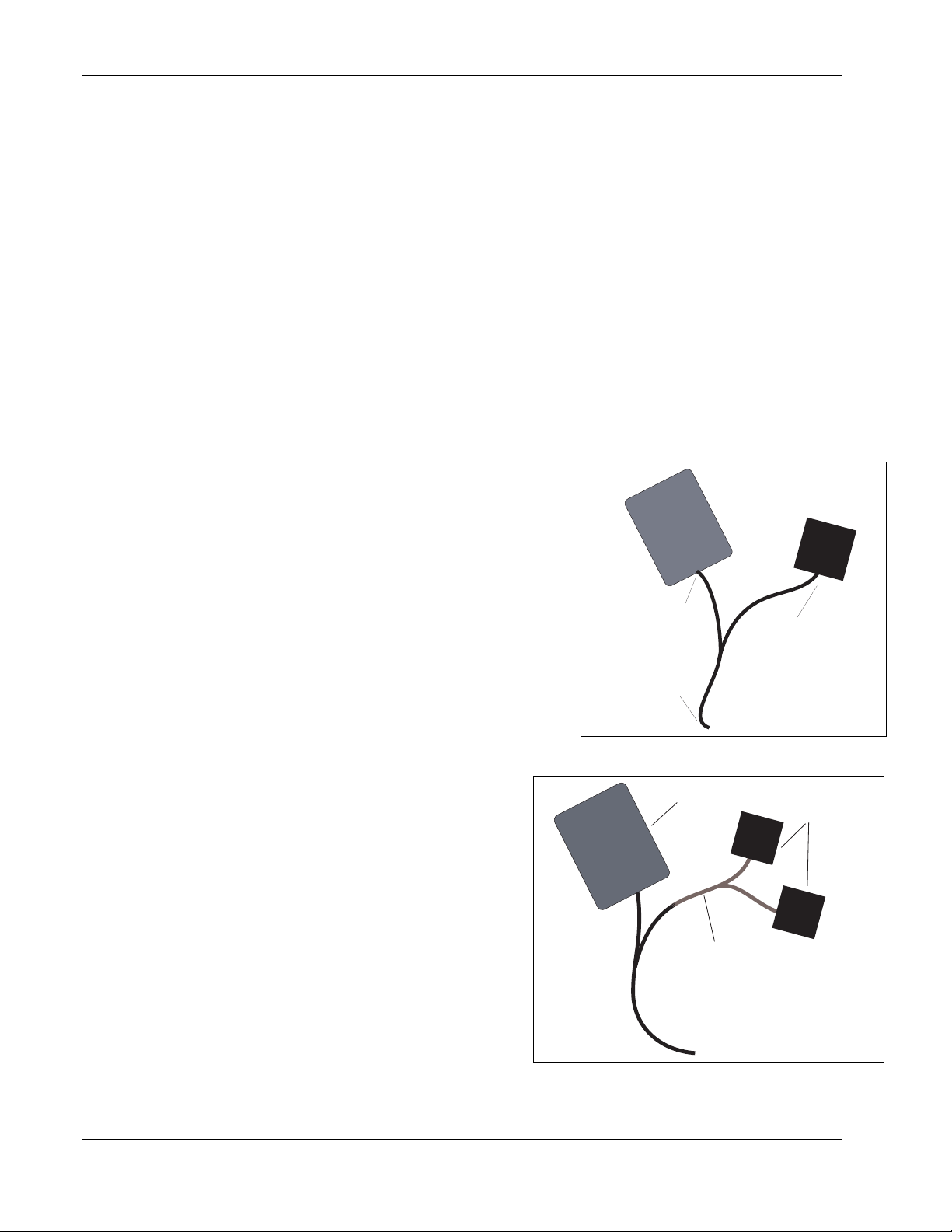
Dynatron Solaris® 700 Series
High Volt Instructions
High Volt electrical stimulation is a pulsed DC current with pulse durations in the
microsecond range and pulse rates ranging from 1 to 200 Hz, with peak amplitude of up to
1.0 amp. The Solaris Series devices deliver High Volt utilizing a twin-peak monophasic
waveform.
High Volt treatments with the Dynatron Solaris Series devices may be delivered using
electrodes or the newly designed MultiStim probe. The device provides a dedicated channel
for High Volt electrodes treatment (HV) and a separate dedicated STIM PROBE JACK for
probes treatments. The Solaris device’s other output channels (1-2-3-4) remain available for
other stim simultaneously treatments.
Set Up High Volt Treatment with Electrodes
This treatment setup utilizes a standard lead wire with
two electrodes; an active and a dispersive electrode.
The size of the dispersive electrode is recommended
to be double the area of the active electrode. If
desired, the active output of the lead wire may be
bifurcated by using an optional bifurcated extension
(Part no. 7B0077) to attach additional active
electrodes. However, the combined total area of the
active electrodes should be no more than half the area
of the single passive electrode, as illustrated.
Press the HI VOLT key to automatically select the
High Volt channel (HV). Connect one lead with two
output connections to the HV channel.
It is best to use a lead that is marked to show polarity.
The active electrode is connected to the
positive output. The dispersive electrode is
connected to the output end that is marked
“HV Dispersive” (-). Carefully attach
electrodes to ensure the polarity selected on
the front panel of the device is delivered.
If desired, a bifurcated lead extension may be
attached to the positive (HV Active) end of
the lead wire, allowing two active electrodes
to be used. In this case, be sure the
dispersive electrode is at least twice the size
(in area) of the combined sizes of the active
electrodes. The bifurcated lead wire
extension is an optional accessory available
through your Dynatronics dealer.
During the treatment current flows in one
direction between the active and dispersive
electrodes. Changing the polarity in the
treatment parameters has the effect of
( – )
Dispersive electrode:
Attach to NEGATIVE
lead output.
DOUBLE
OUTPUT LEAD:
Connect to "HV"
channel
High Volt Electrode Setup
Dispersive electrode
A bifurcated extension may be attached
to the lead to allow TWO active
electrodes if desired. However, the
dispersive electrode should still be twice
the combined size (in area) of the two
active electrodes.
High Volt electrodes with bifurcated active lead.
( + )
Active electrode:
Attach to POSITIVE
lead output.
Active electrodes
HIGH VOLT - Treatment Instructions
52
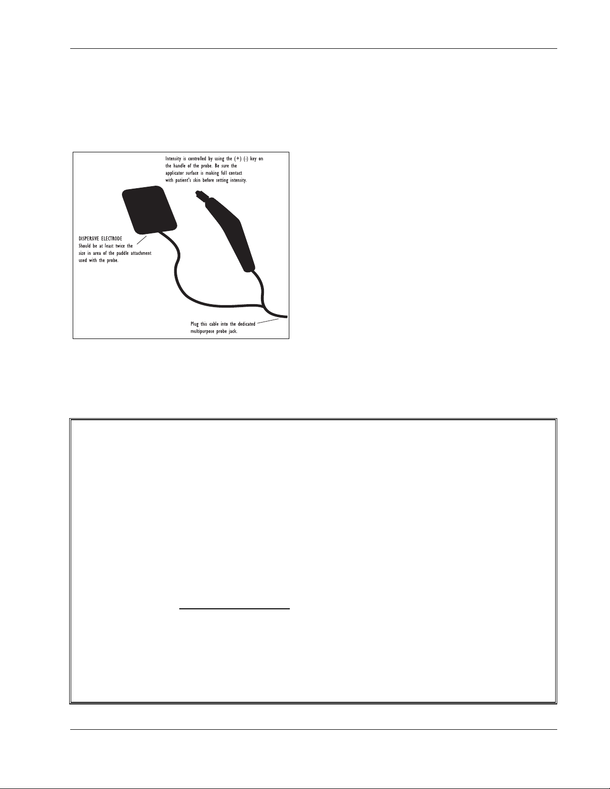
Dynatron Solaris® 700 Series
reversing the direction of the current flow between electrodes. It is important to attach the
active electrode to the HV Active (+) output of the lead wire to ensure you are delivering the
selected polarity. The Lead wires are labeled: HV Active (+), HV Dispersive (-) delivery.
Set Up High Volt Probe Treatment
High Volt Probe Setup
CAUTION: When setting intensity, the probe must be in contact with the patient’s skin. Be
sure that the patient can feel the current as you increase the intensity. Do not increase
intensity for probe treatments if the patient is unable to report feeling the current.
This attended form of High Volt therapy is delivered
using the newly designed MultiStim probe in
conjunction with a dispersive electrode. This handheld probe is connected to the STIM PROBE
OUTPUT JACK located on the left side of the Solaris
device.
The MultiStim probe intensity is controlled on the
probe itself. When using the
CONTRACTION/REST cycle instead of Continuous,
the HIGH VOLT channel display LED begins
blinking when the treatment is in the OFF or “rest”
portion of the cycle. This indicates that the probe may
be repositioned over the next treatment site. By
repositioning the probe only during the “rest” or OFF
portion of the cycle, you ensure that the ramp is
applied when the current again comes ON. The ramp
provides greater patient comfort as the current
resumes.
Basic High Volt Setup
1. Press HI VOLT.
Electrode Treatment
• Plug in lead wire to the HIGH VOLT OUTPUT JACK (HV).
• Attach electrodes to patient at this time.
Probe Treatment
• Press CHANNEL TOGGLE key until the PROBE LED is lighted.
• Plug the MultiStim probe into the STIM OUTPUT JACK.
• Attach dispersive electrode.
2. Choose the POLARITY. (Press FUNCTION key and HI VOLT key simultaneously).
Note: Dual Polarity is not available for probe treatments.
3. For electrode treatments only, change the TIME by using the TIME ARROW keys.
Probe Treatments count up.
4. Choose the CONTRACTION/REST times by using the CONTRACTION/REST
5. Choose the RAMP setting by pressing the RAMP TOGGLE key.
TOGGLE key.
6. Select (or set up) a PULSE RATE RANGE (High/Low) or set a single pulse rate by
using the HIGH/LOW TOGGLE key.
53
Treatment Instructions – HIGH VOLT

Dynatron Solaris® 700 Series
7. Raise the INTENSITY to the desired level. For a probe treatment, make sure probe is
in contact with patient’s skin when raising intensity.
8. Press START. Treatment time will begin to count-down for Electrodes treatment. For
a probe treatment, press ON/OFF on the probe handle after pressing the device START
key to activate the treatment. Time will begin counting up.
9. Press STOP if you need to stop a treatment before the desired time is reached (stops all
current treatments). Press the FUNCTION and STOP KEY together to stop only the
individual displayed treatment. Stop a probe treatment by pressing the ON/OFF key
located on the handle of the MultiStim probe. The treatment time will return to zero.
High Volt Treatment Time
• All PROBE TREATMENTS are manual, and a treatment time is not set. During the
probe treatment, the timer will start at zero and count UP in SECONDS when current is
ON, and will return to zero when current is stopped. To begin a probe treatment, press
START on the device face plate, next press the ON/OFF button on the probe. Pressing
the ON/OFF button on the probe will also stop the treatment and return the time to zero.
If you press STOP on the device, all therapies currently running will be terminated. If
you press Function-Stop, only the High Volt treatment or treatment in focus will stop.
• ELECTRODE TREATMENTS are timed, and a treatment time in MINUTES is
entered at the start of the treatment. The timer counts DOWN for electrode treatments.
Detailed High Volt Setup
1. Press the HI VOLT key.
When you press HI VOLT, the High Volt channel and the default settings for High
Voltage electrode pulsed stimulation are automatically selected. If you have not already
done so, using the dedicated High Volt (HV) channel attach leads and place electrodes on
the patient now. If you choose to select a High Volt Probe treatment, press the
CHANNEL TOGGLE key until the PROBE LED is lighted. See instructions at the
beginning of this section for setting up electrodes or probes treatments. If you wish to
use the default settings, you can now increase intensity to the desired level, then press
START. NOTE: For a probe treatment use the intensity arrows located on the handle of
the probe. Press START on the device faceplate first, next press START on the probe
handle to activate treatment. If you wish to use other settings, follow steps 2 through 8.
2. Choose the POLARITY
Polarity is selected by holding down the FUNCTION key and pressing the HI VOLT key
at the same time. Continue pressing FUNCTION-HI VOLT to select either positive (“+”)
or negative (“-”) polarity or dual polarity (both “+” and “-” LEDs are lighted). NOTE:
The dual polarity option is not available for probe treatments. When both negative and
positive are selected, the device alternates between the two, delivering each polarity for
approximately 30 seconds. Some discomfort may be felt by the patient when the
polarities change. If the patient finds this setup too uncomfortable, you may consider
selecting a monopolar treatment and/or reducing the intensity.
3. Choose the CONTRACTION/REST cycle times.
Press the CONTRACTION/REST TOGGLE key one or more times to select
contraction/rest cycle times. Available options include 10/10, 10/30, 10/50 and
HIGH VOLT - Treatment Instructions
54

Dynatron Solaris® 700 Series
Continuous. The setting of 10/30, for example, means a 10-second contraction time
followed by a 30-second rest time.
CUSTOM CYCLE
The CUSTOM CYCLE is a new feature on the Solaris devices. When the CUSTOM
LED is lighted, the default custom settings are automatically selected. To view or change
the custom settings, after selecting CUSTOM, press the TIME TOGGLE key to select the
ON LED. The value displayed in the TIME display is the ON time in seconds (for
example: 07). Press the TIME TOGGLE key again to select the OFF LED to see the
custom OFF time in seconds (for example: 12). Available ranges for ON time are 3 to 20
seconds, and for the OFF time are 3 to 120 seconds. The OFF time cannot be less than
the ON time. Pressing and holding the START key until the beep is heard will save the
current ON/OFF settings as the default
4. Choose the RAMP setting.
Press the RAMP TOGGLE key one or more times to select the ramp time. Options
include .5, 1.0, 1.5, and 2.0 seconds. The ramp time is applied to both the start and to the
end of the contraction and the ramp time is in addition to the contraction time itself. A
ramp setting is not applied to the Continuous duty cycle except when using a probe.
With a probe treatment set to a Continuous duty cycle, a ramp time of 3 seconds is
applied.
5. Choose HIGH or LOW pulse rate range.
Press the HIGH/LOW TOGGLE key one or more times to select the high range only or
the low range only (this toggle key is found next to the IFC/PREMOD key). The lights
next to the toggle key show which selection is active. In a High Volt treatment, High or
Low only must be selected (the combined High/Low option is not available for High
Volt).
Default High and Low pulse rate ranges for High Volt:
The HIGH range is 80 to 120 Hz.
The LOW range is 1 to 10 Hz.
These ranges may be changed for a single treatment if desired, or new default
settings may also be saved to apply to all future treatment setups.
6. Change the PULSE RATE RANGE (optional)
You may change the pulse rate settings for the High or Low range, if desired. You may
only change the pulse rate range before pressing START to begin the treatment.
When you modify the settings, they will remain in effect for the duration of the treatment.
If you save defaults during this treatment, the new settings you have entered become the
defaults for High Volt. However, if you do not save the new settings, the unit will return
to the current default settings for the next treatment.
First press the TIME TOGGLE key to select RATE. The RATE light will become
GREEN and you will see the current pulse rate range settings displayed in the TIME and
the POWER-INTENSITY displays as shown in the diagram below. Next, press the
HIGH/LOW TOGGLE key to select either the HIGH or the LOW range (this is found
next to the IFC/PREMOD key). With RATE selected and either the HIGH or LOW
range selected, you may use the TIME UP/DOWN ARROW keys to change the upper
and lower limits of the range chosen. If you set both displays to the same value, the
treatment will be delivered at that single pulse rate rather than sweep through a range.
55
Treatment Instructions – HIGH VOLT

Dynatron Solaris® 700 Series
When you are finished setting the pulse rate range, press the TIME TOGGLE key to
return to the TIME display. After 10 seconds with no key presses, the TIME display
automatically returns.
7. Change the treatment TIME, if desired.
To change the treatment time for an electrodes treatment, use the TIME UP/DOWN
ARROW keys. Be sure that the TIME LED located below the TIME display window is
lighted when you make this change. The TIME TOGGLE key allows you to choose the
desired option.
For a probe treatment, the TIME display shows zero until you begin treating. After
pressing the START key on the faceplate of the device, press the ON/OFF button on the
probe to initiate the flow of current. The device beeps once and the timer then counts up
from zero (in seconds) allowing you to time the delivery of current to each treatment site.
When you press the button on the probe to STOP the current, the device beeps twice and
the timer resets to zero.
8. Raise the INTENSITY to the desired level.
Remember, when you increase intensity, current to the patient begins. Therefore, you
should proceed to press START immediately after setting the intensity to begin the
treatment timer. NOTE: The intensity arrows on the probe handle work the same as the
intensity arrows on the device.
Never use High Volt to treat any conditions which contribute to loss of sensation,
and never use High Volt to treat an area where the patient cannot feel the electrical
stimulation.
9. Press START.
Press START to begin an electrodes treatment. When you press start, the treatment
timer begins counting up.
Press START on the device followed by ON/OFF on the probe handle to activate a
probe treatment. The timer will begin counting up. If you fail to set the intensity on
either an electrode or a probes treatment before pressing START, the intensity display
will begin flashing, and you will be unable to start the treatment until you set the
intensity.
NOTE: SAVE DEFAULTS. If the treatment you have just set up is the most common
High Volt setup you use, the treatment parameters can be saved as the defaults for your
own device. After setting up the treatment, simply press and hold the START key for
two seconds. At the end of two seconds, you will hear a beep indicating the treatment
parameters have been saved. The next time you select this modality, these parameters are
selected automatically.
10. MODIFY settings.
While the High Volt treatment is in progress, you can modify the following treatment
parameters.
• Use the CONTRACTION/REST CYCLE TOGGLE keys to select a different
CONTRACTION/REST CYCLE.
• Use the RAMP TOGGLE key to select a different RAMP TIME.
• Use the FUNCTION-HI VOLT keys to change the POLARITY for a Pad treatment.
This feature is not available when using the multi-stim probe.
HIGH VOLT - Treatment Instructions
56
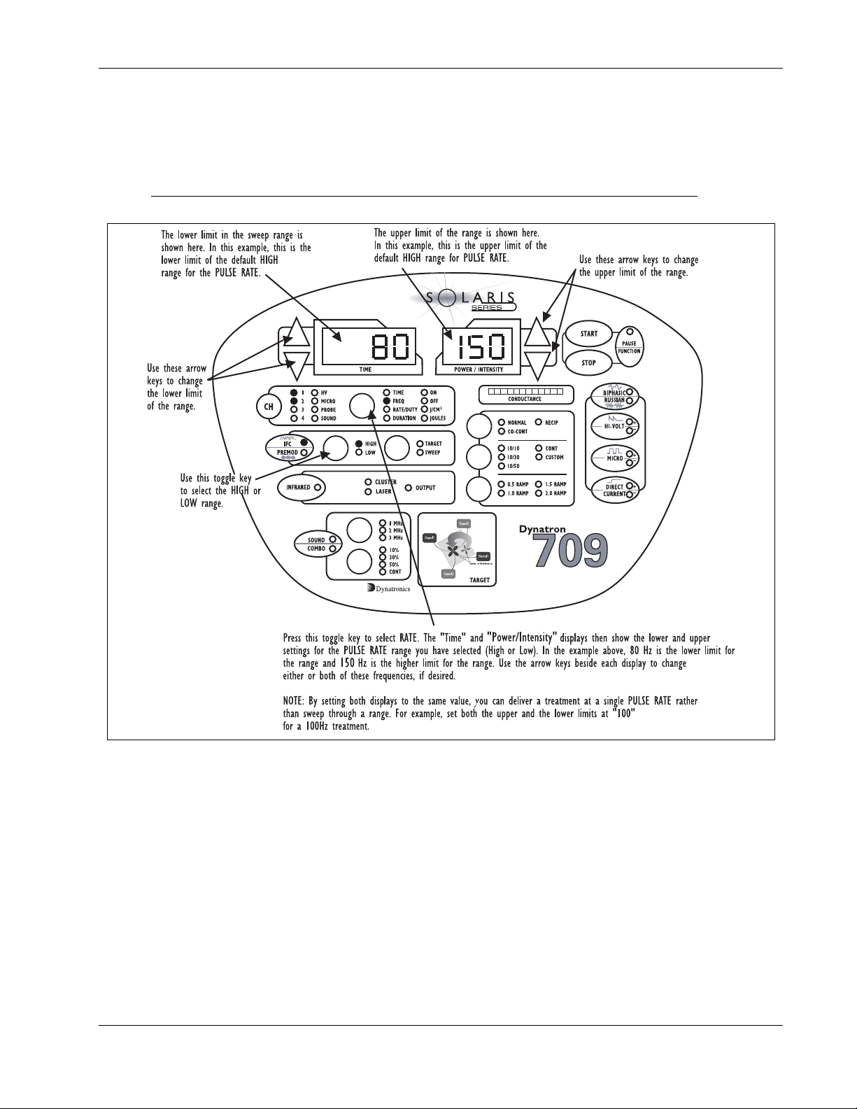
Dynatron Solaris® 700 Series
• Use the TIME ARROW keys to increase or decrease the TREATMENT TIME on
an electrode treatment.
• Use the POWER/INTENSITY ARROW keys to increase or decrease the
INTENSITY.
You can not change from High to Low (or the reverse) once a treatment has started
.
Pulse Rate Range Selection
11. Press STOP, if it is necessary to end the treatment before the treatment time has expired.
NOTE: Pressing STOP will terminate all active treatments.
When the treatment time has elapsed, current to the patient is stopped and a tone sounds
signaling the end of the treatment. Treatments in progress may be stopped at any time
using one of the following methods.
ALL STOP: Press the STOP key to stop treatment at all channels. You may prefer to
stop treatment at one channel only (see explanation below).
STOP ONE TREATMENT ONLY: If you have more than one treatment in progress,
you can stop one treatment by either of the following methods. First, press the
CHANNEL TOGGLE key to select the channel to be stopped (that channel’s light is
GREEN when selected).
Treatment Instructions – HIGH VOLT
57

Dynatron Solaris® 700 Series
FUNCTION-STOP. Press and hold the FUNCTION key and press STOP to
terminate the selected treatment.
REDUCE THE TREATMENT TIME TO ZERO during an electrodes treatment.
Press the TIME DOWN ARROW until the TIME display reaches zero. The device
beeps when the time reaches zero.
MULTISTIM PROBE STOP. A probe treatment may be stopped by pressing the
ON/OFF key located on the handle of the MultiStim probe. The output at the selected
channel is stopped, and the device then displays the parameters for the next treatment that
remains in progress (if any).
HIGH VOLT - Treatment Instructions
58
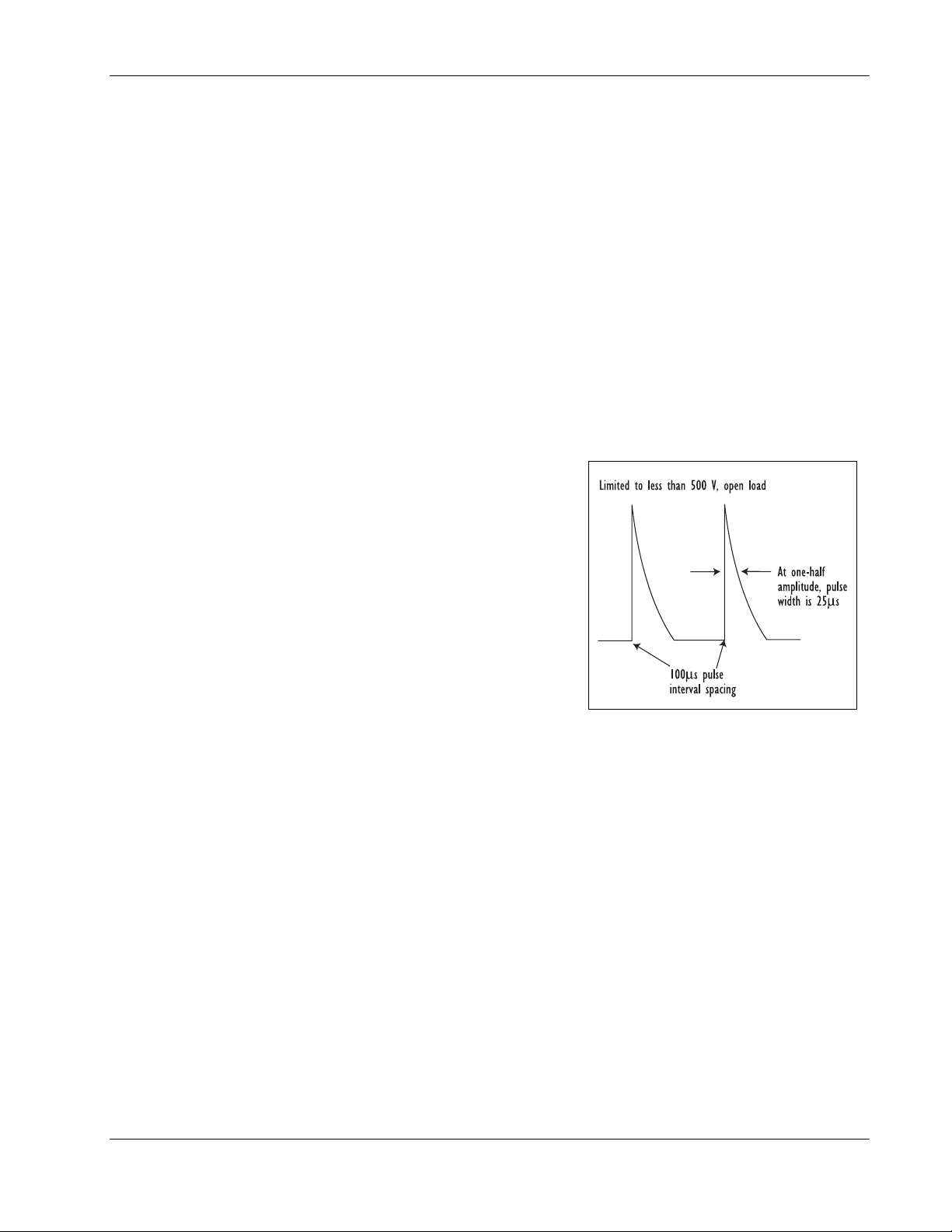
Dynatron Solaris® 700 Series
High Volt
Modality Information
High Voltage pulsed stimulation is a pulsed DC current with pulse durations in the
microsecond range and pulse rates ranging from 1 to 200 Hz, with a peak amplitude of up to
1.0 A utilizing a twin-peak monophasic waveform.
The Dynatron Solaris High Volt treatment setup uses the dedicated channel labeled. Each
treatment utilizes the single HV channel with one or more active electrode and a large
dispersive electrode. Electrodes are placed on opposite sides of the affected area so treatment
is “through” the affected area. The Dynatron MultiStim probe is available to accommodate
hands-on treatment delivery.
High Volt Waveform
The High Volt waveform is a twin-peak
monophasic decaying waveform with either
positive or negative polarity.
High Volt Settings
High and Low Sweep Pulse Rate. The user
may select High (80-120 Hz) or Low (1-10 Hz)
frequency ranges. During a treatment, the device
scans through the range of frequencies selected.
The settings for these pulse rate ranges may be
modified and saved by the user. The available
range is 1 to 200 Hz.
Single Pulse Rate. The pulse rate may be set to
a single pulse rate instead of a range. The pulse
rate is selected from a range of 1 to 200 Hz.
Selectable Polarity. Positive or Negative monophasic current may be selected. You may
also select both positive and negative and the current delivered alternates between the two
polarities. Note: Dual Polarity is not available with a probe treatment.
Selectable Duty Cycle. Continuous or on/off duty cycles may be selected. The Dynatron
Solaris allow you to choose a muscle contraction/relaxation cycle from options of 10/10 (ten
seconds on and ten seconds off), 10/30, 10/50, or continuous cycle. A new feature is the
Custom cycle which allows you to select from an ON time form 3 to 20 seconds, and an OFF
time from 3 to 120 seconds. The OFF time cannot be less than the ON time.
Selectable Ramp Speed. You can choose a ramp speed of 1/2 to 2-1/2 seconds in halfsecond increments. For patient comfort, the ramp occurs both before and after the “On”
segment of the pulse.
Pulse Duration. The pulse duration is fixed at 25 µs.
Pulse Pair Interval. The interval between the two pulses in the wave form is fixed at
100 µs.
High Volt Waveform for positive
polarity
59
Treatment Instructions – HIGH VOLT

Dynatron Solaris® 700 Series
Intensity Display in Volts. The intensity display is shown in volts (peak voltage with no
load) with a range of 1 to 500.
High Volt Default Settings
The following default settings are set by the manufacturer and are selected when you choose
High Volt. You may change these defaults to your own preferred settings. See “Setting
Defaults” in this manual.
• High Volt Pads Treatment
• Continuous Duty Cycle
• Treatment Time Electrodes: 10 minutes
• Treatment Time Probe: 0.00
• Polarity: Negative
• Pulse Rate: High Range
Default High Range: 80-120 Hz
Default Low Range: 1-10 Hz
Available Range: 1-200 Hz
High Volt Waveform Specifications
Waveform: Twin peak, monophasic
Pulse Duration: 25 µs
Pulse Rate Range: 1 to 200 Hz
Pulse Interval: 100 µs
Maximum Power Output: Limited to less than 500 V, open load
HIGH VOLT - Treatment Instructions
60

Dynatron Solaris® 700 Series
Microcurrent Instructions
Microcurrent treatments may be delivered using either electrodes or the MultiStim probe. If
you are not familiar with the operation of the probes see “How to Use the MultiStim Probe”
later in this section. For treatment with electrodes, plug one lead into the CHANNEL 1
JACK, and place the two electrodes on the patient before setting up the treatment. For
treatment with probes, plug the Dynatron MULTISTIM PROBE into the STIM PROBE
JACK located on the left side of the device.
During the Microcurrent treatment the current is delivered to both CHANNEL 1 and to the
MULTISTIM PROBE output simultaneously. Therefore, CHANNEL 1 is unavailable for
any other treatment while any Microcurrent treatment is in progress (including a single
Microcurrent probe treatment).
NOTE: Microcurrent is unavailable if Direct Current or a Dynatron Light Therapy treatment
is selected.
How To Use The MultiStim Probe For Microcurrent Treatments
To set up a Microcurrent Probe treatment, use the end of a cotton swab (such as a Q-Tip
inserted into the end of both the MultiStim probe (active) and Microcurrent Ground probe.
Cut the end of the swab to a short length. The cotton must touch the metal ring at the tip of
the probe. Use a conductive electrolyte spray or water to wet the cotton swab before treating.
If the cotton dries out during treatment, conductance may become erratic. Re-wet the cotton,
if needed. Note: When applying a Microcurrent probe treatment, it is necessary to use
either a ground probe or a ground electrode in conjunction with the active MultiStim
probe. Attach the banana plug ground wire from the MultiStim probe by plugging it into the
back of the ground probe. To use a ground electrode you must use a banana-to-pin adapter
to connect the ground wire to the electrode.
ACTIVE PROBE: To deliver the current to the patient through the active MultiStim probe,
first set up the probe treatment and press Start. Then hold the probe as you would
hold a pencil, and press the ON/OFF button on the probe to start delivery of the current. The
active probe should touch the patient’s skin at the treatment site, and the ground probe should
touch the patient’s skin elsewhere near the treatment site. This completes the circuit and
delivers current to the patient. You do not need to hold the ON/OFF button down. Once you
have pressed and released the button, the current is delivered until you press and release the
button again to stop the current. The unit beeps once
current, and beeps twice
when you press the button to stop the current.
While you are delivering current, the treatment timer counts up in seconds from zero. When
the current is stopped, the timer returns to zero. Press the ON/OFF button again to
commence the next treatment cycle. Continue in this way until treatment is completed.
GROUND PROBE: The ground probe is used to complete the circuit allowing the flow of
current through patient tissue. The ground probe should touch the patient’s skin at any
location away from the treatment point. As an alternative, you may also use a dispersive
electrode as explained below. With the ground electrode you do not need to hold the ground
probe in your hand during treatment. This is particularly convenient when treating in several
different places around one point.
when you press the button to start the
®)
61
Treatment Instructions – MICROCURRENT
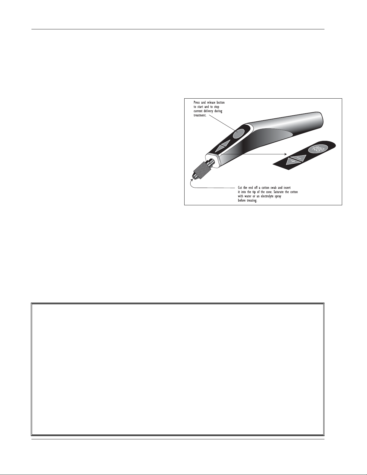
Dynatron Solaris® 700 Series
GROUND ELECTRODE: You can use an electrode in place of the ground probe. Just
unplug the ground probe from its cable, attach a banana to pin adapter to the cable, then
attach an electrode to the pin. Place the electrode on the patient at a site where it will not
interfere with placement of the active probe during treatment.
TREAT: After pressing START on the faceplate of the device, press and release the
ON/OFF button on the active MultiStim probe to start current delivery. The unit beeps once
to indicate current delivery has
started. When the active MultiStim
probe and a ground probe touch the
patient’s skin, the current is delivered
to the patient.
Observe conductance by listening to
the audio tone. In addition, the
CONDUCTANCE BAR GRAPH will
indicate the conductance between
patient skin and probe tip, allowing
for an optimum treatment.
TEST Mode: Press and release the
ON/OFF button again to stop delivery
of the current. The unit beeps twice
to let you know current delivery has
MultiStim Probe
stopped. The probe is now in
“TEST” mode allowing you to
continue monitoring conductance at any point desired. When the probe touches the patient’s
skin, conductance continues to be measured and the audio tone is produced. Press and release
the button when you wish to return to the TREAT mode.
NOTE: In “TEST” mode during a Microcurrent treatment, a small amount of current is
delivered to allow an impedance reading to be taken in order to show conductance. The
current delivered during “TEST” mode is either 25 micro amperes or the micro amperage
setting for the treatment itself, whichever is less. For purposes of this measurement, current
is delivered in pulses of approximately 20 mSec.
Basic Microcurrent Setup
1. Press the MICRO key.
2. The Solaris device will automatically choose treatment CHANNEL 1 for electrodes.
3. For a PROBE treatment, use the TIME CHANNEL TOGGLE key to select PROBE,
4. Choose the POLARITY (press FUNCTION key and MICRO key simultaneously).
and insert the MultiStim probe into the STIM OUTPUT jack.
5. For electrode treatments only, change the TIME by using the TIME ARROW keys, if
desired.
6. Change the FREQUENCY, by pressing the TIME TOGGLE key until the FREQ
selection is lighted, then using the TIME ARROW keys, select the desired frequency.
7. Change the INTENSITY setting, by using the POWER/INTENSITY ARROW keys or
8. Press START. The AUDIBLE TONE is selected as a default for a probe treatment.
MICROCURRENT – Treatment Instructions
the (+) & (-) switch in the probe handle, if desired.
62

Dynatron Solaris® 700 Series
9. Press MICRO again to turn AUDIBLE TONE on/off, as desired. Press Function-Time
Toggle to turn on/off the Conductance Bar.
10. Press STOP if you need to stop a treatment before the treatment time is complete (stops
all current treatments). Use the TIME arrow keys to bring treatment time to zero or
press the FUNCTION and STOP KEY together to stop only the individual displayed
treatment. PAUSE a Microcurrent probe treatment by pressing the ON/OFF key located
on the MultiStim probe handle.
Microcurrent Treatment Time
• All probe treatments are manual, and a treatment time is not set. During the probe
treatment, the timer will start at zero and count UP in SECONDS when current is ON,
and will return to zero when current is stopped. You must press START on the device
face plate to begin the treatment and automatically activate the tone before you begin the
treatment. Then press the ON/OFF button on the probe to start and stop delivery of
current. Press STOP (stops all therapies currently running) or Function-Stop (stops only
Microcurrent or treatment in focus) to terminate Micro probe treatment.
• Electrode treatments are timed, and a treatment time in MINUTES is entered at the start
of the treatment. The timer counts DOWN for electrode treatments.
Detailed Microcurrent Setup
Before setting up a Microcurrent treatment with electrodes, attach a lead wire with two
electrodes to CHANNEL 1 or, for a probes treatment, connect the MULTISTIM PROBE to
the STIM OUTPUT JACK on the left side of the device. When a MULTISTIM PROBE
treatment is in progress, Channel 1 is not available for any other use.
1. Press the MICRO key.
When you press the MICRO key, the default settings are automatically selected. If you
wish to use the default settings, you can now simply press START. If you wish to use
other settings, complete steps 2-6.
2. Choose the output desired, select CHANNEL 1 (for electrodes treatment). For a probe
treatment, press the CHANNEL TOGGLE to select PROBE (the green LED will be
lighted) and insert the MULTISTIM PROBE into the STIM PROBE JACK.
3. Choose POLARITY.
While holding the FUNCTION key, press the MICRO key at the same time to select the
desired polarity. Press once to select positive (“+”), press again to select negative (“-”),
and press again to select dual polarity (both “+” and “-” LEDs are lighted). When both
positive and negative are selected, the resulting bipolar waveform includes both a
positive and a negative phase.
4. For electrode treatments only, change the TIME, if desired.
To change the treatment time, use the TIME UP/DOWN ARROW keys. Be sure that the
TIME LED located below the TIME display window is lighted when you make this
change. The TIME TOGGLE key allows you to choose the desired option.
For probes treatment, the TIME display shows zero until you begin treating. After
pressing the START key on the faceplate of the device, press the ON/OFF button on the
probe which will initiate the flow of current. The device beeps once and the timer then
63
Treatment Instructions – MICROCURRENT

Dynatron Solaris® 700 Series
counts up from zero (in seconds) allowing you to time the delivery of current to each
treatment site. When you press the “1/0” key on the probe to stop the current, the device
beeps twice and the timer resets to zero.
5. Change FREQUENCY, if desired.
To change the frequency, use the TIME TOGGLE key to select FREQ, next use the
TIME UP/DOWN ARROW keys to change the frequency. You can press the TIME
TOGGLE key again to return to the TIME display, if desired. However, if you make no
key presses for 10 seconds, the display automatically returns to the TIME display.
6. Change the INTENSITY setting.
This setting is displayed in micro amperes in the POWER-INTENSITY window. Use the
POWER-INTENSITY Up/Down Arrow keys to change the intensity.
For Electrodes treatments, the CHANNEL 1 indicator light is GREEN. For a probe
treatment the MICRO channel light is GREEN and the CHANNEL 1 light is YELLOW.
Changes you make will affect output to both the probe and Channel 1
.
7. Press START.
For electrode treatments, when you press START the treatment timer begins counting
down and stim is delivered through Channel 1.
For probe treatments, after pressing START you must press and release the ON/OFF
button on the probe to activate current through the probe; the device beeps once to signal
that current delivery has started (it is not necessary to hold the button down while
treating). The treatment timer begins counting up in seconds from zero to provide a
convenient means of timing the delivery of current at a given point. Press and release the
ON/OFF button again to stop the current through the probe; the treatment timer returns to
zero and the device beeps twice to signal that current delivery has stopped. Continue the
treatment cycle in similar fashion for each treatment site. When applying a Microcurrent
Probe treatment, it is necessary to use a ground probe or ground electrode in conjunction
with the treatment.
NOTE: SAVE DEFAULTS. If the treatment you have just set up is the most common
Microcurrent setup you use, you can save the treatment parameters as new defaults for
your own machine. After setting up the treatment, simply press and hold the START key
for two seconds. At the end of two seconds, you will hear a beep indicating the treatment
parameters have been saved. The next time you select the MICRO modality, these
parameters are selected automatically. Separate default parameters may be saved for both
treatments with electrodes and with probes. See “Setting Defaults” located at the end of
this section of the manual for further instructions.
8. Turn AUDIBLE TONE ON/OFF, and/or adjust volume.
The audible tone allows you to monitor conductance, if desired. As conductance
increases (as resistance is decreased), the tone becomes higher in pitch.
The audible tone is defaulted to ON for a probe treatment and OFF for electrodes
treatments, but may be changed. After the Microcurrent treatment has started the
MICRO key acts as a toggle key to turn the tone ON and OFF. Press MICRO to turn the
tone ON or OFF.
You may also adjust the tone volume after the treatment has started. To adjust the
volume, PRESS and HOLD the FUNCTION key and at the same time use the
POWER/INTENSITY ARROW keys to raise or lower the volume until a comfortable
volume setting is found. The POWER/INTENSITY display will temporarily show an
MICROCURRENT – Treatment Instructions
64

Dynatron Solaris® 700 Series
incremental value (0-30) representing the volume selection. You must continue holding
the FUNCTION key down while adjusting the volume. When you release the
FUNCTION key, the POWER/INTENSITY display returns to its normal setting.
9. MODIFY a treatment in progress.
While the treatment is in progress, you can modify the treatment parameters.
• Press the FUNCTION-MICRO key to select a different polarity.
• Use the TIME TOGGLE key to select TIME then use the TIME ARROW keys to
increase or decrease the treatment time.
• Use the TIME TOGGLE key to select FREQ, then use the TIME ARROW keys to
increase or decrease the frequency.
• Use the POWER/INTENSITY ARROW keys to increase or decrease the intensity.
10. Press STOP, if it is necessary to end the treatment before the treatment time has expired.
When the treatment time has elapsed, current to the patient is stopped and a tone sounds
notifying you of the treatment end. Treatments in progress may be stopped at any time
using one of the following methods.
ALL STOP: Press the STOP key to stop treatment at all channels. You may prefer to
stop treatment at one channel only (see explanation below).
STOP ONE TREATMENT ONLY: If you have more than one treatment in progress,
you can stop one treatment by either of the following methods. First, press the
CHANNEL TOGGLE key to select the channel to be stopped (that channel’s light is
GREEN when selected).
FUNCTION-STOP. Press and hold the FUNCTION key and press STOP to
terminate the selected treatment.
REDUCE THE TREATMENT TIME TO ZERO. Press the TIME DOWN ARROW
until the TIME display reaches zero. The device beeps when the time reaches zero.
The output at the selected channel is stopped, and the device then displays the parameters
for the next treatment that remains in progress (if any).
65
Treatment Instructions – MICROCURRENT

Modality Information
Microcurrent is low-volt pulsed microamp stimulation which has been used for symptomatic
relief of chronic intractable and post-surgical pain. With the Dynatron Solaris you can
provide attended or unattended Microcurrent therapy. Unattended therapy is delivered using
electrodes. Attended therapy is delivered using the Dynatron hand-held MultiStim probe.
Due to the very low frequencies generally associated with a Microcurrent treatment, the
current is commonly not felt by the patient. However, Microcurrent at high intensity settings
or during a probe treatment, can sometimes be felt by the patient, and may even be
uncomfortable. During a probe treatment, this is a result of current being concentrated at a
very small area.
As with all forms of electrotherapy, current density is dependent upon the current setting, the
intensity setting, the size and type of electrodes used, and conductance. Higher current
density increases the possibility for patient discomfort. The current density can be reduced
by decreasing the amount of current (intensity) or increasing the area through which the
current is being delivered. The area can be increased by using larger electrodes and/or
making sure that the total area of the electrode is actually delivering current.
Microcurrent Waveforms
Three different output
waveforms (polarities) may be
selected with the Dynatron
Solaris: The first two are
unipolar square waves having
a monophasic pulse at a 50
percent duty cycle (equal on
and off times). In the
illustration above, the first
unipolar waveform has
negative polarity only, and the
second has positive polarity
only. The third waveform is a bipolar (negative and positive) square wave with a 50 percent
duty cycle.
Microcurrent Guidelines
When delivering Microcurrent therapy, observe the following guidelines:
1. Use only moderate current. Consult published literature for recommended settings for
Microcurrent treatment.
2. When using Microcurrent probes, keep in mind that all of the current is delivered through
the tip of the probe resulting in much higher current density than when using electrodes.
Therefore, low to moderate intensity settings will be much more comfortable for the
patient, especially when treating sensitive areas.
Dynatron Solaris® 700 Series
Microcurrent
Microcurrent Waveform
MICROCURRENT – Treatment Instructions
66

Dynatron Solaris® 700 Series
3. When using electrodes, ensure that the area on the patient’s skin where the electrode is to
be placed is clean and free of all foreign matter. This includes powders, perfumes, and
the like, as well as body oils or dirt and grime. Cleaning with an alcohol wipe should be
adequate. Allow the alcohol to fully evaporate before applying the electrodes.
Iontophoresis occurs with all electrical current therapies, and can drive any above-surface
contaminants below the epidural layer, where an allergic reaction may occur.
4. Make sure the electrodes being used are in good condition. The poly adhesive electrodes
should have good adhesion over the entire surface area of the electrode. The area where
the leads attach to the electrode (either the pin connector or a snap) should not be
damaged such that the connection to the backing behind the adhesive is broken. Carbon
electrodes should be deep black, and should be free of cracks in the electrode surface.
5. Some patients tend to be much more sensitive to Microcurrent treatments. On patients
with this tendency, treat with reduced intensity and/or shorter treatment times, with
possibly more frequent treatments, if required.
6. If electrodes are placed on an uneven skin surface, such as over a raised mole, the
electrode may not adhere evenly over its entire surface and current could be intensified at
the raised area, causing discomfort to the patient.
Microcurrent Default Settings
The following default settings are set by the manufacturer and are selected when you press
Micro. You may change these defaults to your own preferred settings. See “Setting
Defaults” in this manual.
Electrodes
The Microcurrent treatment setup with electrodes is the default, and the following defaults are
also selected:
• Bipolar wave
• .3 Hz frequency
• 50 µA intensity
• Time: 20 minutes, counts down
• Audible Tone: Off
Probe
If Probe treatment is selected, the following defaults are automatically selected:
• Negative unipolar wave
• 4 Hz frequency
• 300 µA intensity
• Time: zero, counts up
• Audible Tone: On
Available Ranges:
• Frequency: Between .1 and 200 Hz
• Maximum (open circuit) Voltage: 60V
• Intensity: Between 10 and 990 microamps open load, constant current, increments of
10µA.
The ranges of .1 to 200 Hz frequency and between 10 and 990 micro amperes intensity are
available for setting up both electrodes and probes treatments. For guidance in selecting the
appropriate frequency and intensity for a given probes or electrodes treatment, consult
published medical literature.
67
Treatment Instructions – MICROCURRENT

Dynatron Solaris® 700 Series
Direct Current Instructions
Direct Current flows in one direction. From a practical perspective, Direct Current can be
defined as having a pulse duration long enough to depolarize skeletal muscle when the nerve
is not intact. On the Solaris line of devices, Direct Current is a square wave interrupted with
a set interpulse duration of 500 mSec. The interrupted treatment is delivered in a continuous
train of 0 .1 mSec to 500 mSec pulses set at a maximum of 20 mA. Duration, Intensity, and
Polarity settings may be adjusted separately, if desired. The Polarity may be set at Positive or
Negative. Treatment is provided only through the MultiStim probe. The use of various
attachments and a dispersive electrode are necessary. The MultiStim probe utilizes the Stim
Probe Output Jack located on the left side of the Solaris device. ON/OFF controls and
INTENSITY keys (+/-) are located on the MultiStim probe handle.
Direct Current Setup
1. Choose DIRECT CURRENT.
2. Plug the MULTISTIM PROBE into the STIM PROBE OUTPUT JACK and attach
the dispersive electrode.
3. Choose POLARITY. Note: Polarity setting defaults to Negative.
4. Set the DURATION of each DC pulse.
5. Place probe tip in contact with patient’s skin.
6. Press the START key followed by the ON/OFF key located on the MultiStim probe.
7. RAMP UP INTENSITY by using the POWER INTENSITY KEYS (+) and (-) keys
located on the handle of the probe. Caution: Probe must be in contact with patient’s skin
8. Treatment will continue until the OFF key on the MultiStim probe is pressed.
prior to starting treatment.
Detailed Direct Current Setup
1. Press the DIRECT CURRENT key.
When you choose DIRECT CURRENT, the STIM PROBE OUTPUT JACK is
automatically selected.
2. Plug the MultiStim probe into the OUTPUT JACK and attach the dispersive electrode.
The default settings for the modality are programmed at 100 mSec, and Negative
polarity. If you wish to use the default settings, attach dispersive electrode and place
probe in contact with the patient’s skin. You can now press START on the device
followed by the ON/OFF key on the MultiStim probe handle. There is no need to hold
down the key. Current delivery will commence and you can begin ramping up the
intensity by using the POWER INTENSITY (+) (-) KEYS located on the Probe handle
until the desired muscle contraction is obtained.
If you wish to change the treatment settings, complete the steps on the following pages.
DIRECT CURRENT – Treatment Instructions
68

Dynatron Solaris® 700 Series
3. Set PULSE DURATION
The default PULSE DURATION time is displayed at 100 mSec in the TIME display
window. Use the TIME ARROW keys to increase or decrease the PULSE DURATION
between 0.1 mSec and 500 mSec per pulse. Pulse Duration selections available are 0.1,
0.3, 0.5, 1, 10, 100, 500, with an interpulse duration of 500 mSec. The selected pulse
duration will be delivered in a continuous train of pulses set up to a maximum of 20 mA.
4. Choose POLARITY
Polarity for a DIRECT CURRENT probe treatment will default to Negative (-). You
may change the Polarity setting by pressing the FUNCTION key and the DIRECT
CURRENT key at the same time, then while continuing to hold down the FUNCTION
key toggle the DIRECT CURRENT key to (+) Positive (the GREEN LED next to (+) will
be lighted or back to (-) Negative (the GREEN LED next to (-) will again be lighted).
Note: Polarity may be changed during treatment.
5. Place the probe in contact with the patient’s skin before pressing START.
6. START the DC treatment by pressing the START key located on the faceplate of the
device followed by pressing and releasing the ON/OFF key located on the MultiStim
Probe handle. When the ON key is pressed, a single beep will be heard, followed by one
beep every second as long as the DC current continues to flow.
7. INTENSITY defaults at “1.” After the ON key has been pressed, begin ramping up the
intensity by pressing the POWER/INTENSITY UP arrow key or by pressing the (+) (-)
keys on the handle of the MultiStim probe. The INTENSITY may be set up to 20 mA.
When the desired muscle contraction has been reached, press the ON/OFF key on the
probe handle to end the treatment.
Before selecting the intensity setting for an individual patient, see “Electrotherapy Usage
Cautions” in this manual for recommended intensity settings. Also see the section of this
manual entitled “Contraindications, Warnings, and Precautions” for specific precautions
when treating any conditions contributing to loss of sensation, or anytime the patient
cannot feel the electrical stimulation.
8. STOP the DC treatment by pressing and releasing the ON/OFF key located on the
MultiStim Probe handle. When the ON/OFF key on the probe handle is pressed, two
quick beeps will be heard indicating that the DC treatment is complete.
SAVE DEFAULTS. If the treatment you have just set up is a frequently used treatment
setup, you can save the treatment parameters as new defaults for your own machine. After
setting up the treatment, simply press and hold the START key located on the Solaris
device until you hear a beep indicating the treatment parameters have been saved. The next
time you select that modality, these parameters are selected automatically.
NOTE: The intensity setting is not saved but must be reset with each individual
patient.
69
Treatment Instructions – DIRECT CURRENT

Dynatron Solaris® 700 Series
Direct Current
Modality Information
Direct Current is electrical current that flows in one direction. Direct Current has been
clinically used for: 1) Performing strength duration curve tests, 2) Stimulating denervated
muscle following peripheral nerve injury.
On the Solaris line of devices, Direct Current is a square waveform interrupted with a set
interpulse duration of 500 mSec. The treatment is delivered in a continuous train of 0.1 mSec
to 500 mSec pulses set at a maximum of 20 mA. Duration, Intensity, and Polarity settings
may be adjusted separately, if desired. The Polarity may be set at Positive or Negative.
Treatment is provided only through the MultiStim probe. The use of various attachments and
a dispersive electrode are necessary. The MultiStim probe utilizes the Stim Probe Output
Jack located on the left side of the Solaris device. ON/OFF controls and INTENSITY keys
(+/-) are located on the MultiStim probe handle.
Direct Current Probes Therapy
The Dynatron Solaris Direct Current treatment setup uses the MULTISTIM PROBE with the
STIM PROBE JACK as its dedicated channel. The treatment is normally delivered with a
paddle adapter accompanied
by a large dispersive electrode
or ground probe acting to
complete the circuit. Note:
Electrodes and Probe must be
in contact with the patient
prior to beginning therapy.
Direct Current Waveforms
The Direct Current wave form
is a square wave with
adjustable duration times.
Duration will default to 100
mSec, but may be set from
0.1 mSec to 500 mSec.
Duration selections available
are 0.1, 0.3, 0.5, 1, 10, 100, 500, with an interpulse duration of 500 mSec. The variable Pulse
Duration is interrupted with a interpulse duration of 500 mSec.
Note: Load impedance does not affect output of the waveform.
Direct Current Cautions
It is important that excellent coupling be maintained any time current is flowing. Increased
resistance from poor coupling or excessive current density can cause skin reactions.
CAUTION: Electrodes must be attached and probe placed in contact with the patient’s skin
prior to starting the treatment.
Direct Current with Variable Pulse Duration Times
DIRECT CURRENT – Treatment Instructions
70

Dynatron Solaris® 700 Series
Note: Direct Current tends to lower surface sensory perception as the treatment proceeds.
The patient must have good sensory perception if Direct Current is to be used.
Direct Current Default Specifications
Direct Current Specifications
• Waveform: Square
• Pulse Duration: .1-500 mSec
• Pulse Duration Selections: 0.1, 0.3, 0.5, 1, 10, 100, 500
• Inter-Pulse Duration: 500 mSec
• Power Output: 20 mA.
Note: Load impedance does not affect output of the DC waveform.
Direct Current Default Settings
The following default settings are set by the manufacturer and are selected when you select a
DIRECT CURRENT PROBE treatment. You may change these defaults to your own
preferred settings. See “Setting Defaults” in this manual.
Direct Current Default Settings
• Pulse Duration: 100 mSec
• Polarity: Negative
• Intensity: 1
71
Treatment Instructions – DIRECT CURRENT

Dynatron Solaris® 700 Series
Infrared Light Therapy
Operating Instructions
Utilizing state-of-the-art technology, the new Dynatron Solaris devices deliver therapeutic energy
through one of four innovative Solaris treatment probes or the new Dynatron Xp Infrared Light Pad.
The Solaris Infrared Light Therapy probes are specifically designed for treating smaller areas. The
probes have a treatment area of 5 cm
skin over the treatment area. To treat areas larger than 5 cm
one at a time in a grid pattern until the desired treatment area is covered unless treating large areas
where the Dynatron Xp (8”X10”) pad would be more suitable. Please see published literature for
specific treatment parameters.
There are five accessory treatment options:
• D880 INFRARED CLUSTER PROBE: The Solaris D880 Infrared Cluster Probe is
designed with 32 infrared super luminous diodes emitting a wavelength of 880nm
and 4 red diodes emitting a wavelength of 660nm.
• D880 PLUS INFRARED CLUSTER PROBE: The Solaris D880 Plus Infrared
Cluster Probe is identical to the D880 probe with the exception of the power that is
delivered. The D880 Plus probe has a maximum power output of 900mW compared
to the maximum power output of the D880 probe of 500mW, thus reducing total
treatment time.
• D890 INFRARED LIGHT PROBE: The Solaris D890 Light Probe incorporates one
laser diode emitting a wavelength of 875nm and 3 red diodes emitting a wavelength
of 660nm.
• D405 INFRARED/BLUE LIGHT PROBE: The Solaris D405 probe is an Infrared
Light probe designed with 8 Infrared diodes emitting a wavelength of 880 nm and 28
Blue diodes emitting a wavelength of 405nm.
• DYNATRON Xp INFRARED LIGHT THERAPY PAD: This unattended Infrared
Light Therapy Pad consists of 200 infrared diodes emitting wavelengths of 880nm.
The Xp’s flexibility makes it easy to treat any part of the body. A Booster Box is
required when using the Dynatron XP Infrared Light Pad.
The Solaris Infrared Light Therapy Probes and the Dynatron Xp Pad have been cleared by the FDA to
provide topical heating for temporary increase in blood circulation, temporary relief of minor muscle
and joint aches, pain and stiffness and relaxation of muscles; for muscle spasms and minor pain and
stiffness associated with arthritis.
CAUTION: The Solaris Light Therapy probe and the Dynatron Xp Pads must be plugged securely
into the respective output jacks prior to turning ON the Solaris base console or Booster Box.
WARNING: Exposure to Blue Light poses an optical risk. Protective eyewear is therefore required
when using the D405 probe.
2
and should be applied in direct contact with the surface of the
2
, individual treatments should be given
INFRARED LIGHT THERAPY - Treatment Instructions
72

Dynatron Solaris® 700 Series
Infrared Light Therapy Treatment Setup
1. Remove all gels and lotions from skin surface.
2. Booster Box: If using a Booster Box, plug the Booster Box communication cable into
3, While the Solaris console/Booster Box devices are turned OFF, plug the Light
4. When using the D405 probe, place protective eyewear on both the patient and the
5. Turn ON the Solaris/Booster Box devices.
6. Select LIGHT THERAPY on the Solaris console.
Probe. The PROBE LED is lighted and the device is in Light Probe mode.
Pad. Press the CH toggle key. The PROBE LED will go off and the
7. Select TREATMENT SETTINGS: Frequency/Rate Duty (probe only) and Dosage.
8. START. Press START on the faceplate of the device.
Pad. The Light Pad treatment will immediately begin when START is
Probe. Press the 1/0 (ON/OFF) key located on the Probe handle to begin
9. PAUSE.
Pad. Press the Pause/Function key located on the face plate of the Solaris
Probe. Press the 1/0 (ON/OFF) key located on the Probe handle. To continue the
10. STOP.
Pad. Press the FUNCTION and STOP KEY simultaneously to stop only the
Probe. Treatment will continue until the 1/ 0 (ON/OFF) key on the Light
CAUTION: Pressing STOP on the faceplate of the device will terminate all Solaris
the base of the Solaris Console while power to the Booster Box and the console are OFF.
Therapy Probe and/or Xp Pad into the corresponding output jacks on the Solaris console
or Booster Box.
practitioner.
device is in Light Pad mode. D701: Press the UP ARROW key next to the TIME
display window.
pressed.
treatment.
console. To continue the treatment, press the Pause/Function key again.
treatment, press the 1/0 (ON/OFF) key again.
displayed pad treatment or allow the treatment to automatically time out.
Therapy Probe is pressed, pausing the treatment or the treatment automatically
times out.
treatments in progress.
Detailed Treatment Setup
1. CLEANSE THE TREATMENT AREA to insure that all gels and lotions have been
removed from the surface of the skin. DO NOT
therapy. Using gels will degrade the optical coating on the lens resulting in a loss of
output power and efficacy. Gels will clog the vents causing overheating and damage to
use gels in combination with light
Treatment Instructions – INFRARED LIGHT THERAPY
73

Dynatron Solaris® 700 Series
the internal components. Damage caused by the use of gels and lotions may void your
warranty.
2. If using the Dynatron XP Pad, attach the Booster Box to the Solaris base console by
plugging the Booster Box communication cable (labeled SOLARIS CONNECTION) into
the IR/RED output jack located on the right side of the Solaris unit. When connecting the
Booster Box, both units should be turned OFF.
3. WHILE THE BASE SOLARIS/BOOSTER BOX UNITS ARE TURNED OFF
the Solaris Light Therapy Probe and/or Dynatron Xp Pad into their proper output jacks.
The Light Therapy Probe should be inserted into the IR/RED Probe output jack located
on the base console of the Solaris device, or on the left side of the Booster Box. The Xp
pad should be plugged into the Xp Pad output jack located on the right side of the
Booster Box. Carefully align the connector “keys” to avoid damage to the pins when
inserting the probe/pad into the jack(s).
4. When using the D405 probe, place protective eyewear on both the patient and the
practitioner.
5. POWER-ON THE DEVICE(S). After the pad and/or probe are plugged into the proper
output jack(s), select the “1” (ON) position on the power switch(s) located on the rear
panel(s) of the base console and the Booster Box (if applicable). If a probe or pad has not
been properly attached, an error message “Irhd” will appear in the time display window
indicating that the devices must be turned OFF and the probe/pad connections carefully
checked. It is recommended, if the pad/probes are used frequently, that the unit remain
ON with the Solaris Light Therapy devices plugged into the Solaris console/Booster Box
throughout the day. When switching to a different probe/pad, turn the Solaris
console/Booster Box OFF and repeat step 2 above.
6. Select LIGHT THERAPY on the Solaris console.
Probe. The PROBE LED is lighted and the device automatically defaults to the
Infrared Light Probe mode. The probe is activated in preparation for treatment.
Xp Pad. After pressing Light Therapy, press the CH toggle key. The PROBE LED
goes off and the device is in Pad mode. To place the D701 in Pad mode, press the
UP ARROW key next to the TIME display window.
CAUTION: The Xp Light Pad should not be flexed smaller than a 5” diameter.
Applying flexion that forces a diameter smaller than 5” may cause the pad to fail.
7. SET DOSAGE (Total Energy Delivered)
Dosage is calculated as a combination of time and Joules/cm
by pressing the UP/DOWN ARROW keys located next to the POWER/INTENSITY
display window to increase or decrease the desired number of J/cm
treatment protocol. For further instructions for the Xp Pad treatment setup, proceed to
step 8 after setting the dosage.
INFRARED LIGHT THERAPY - Treatment Instructions
74
, insert
2
. Dosage may be selected
2
for the prescribed

Dynatron Solaris® 700 Series
Note: TIME is automatically calculated by the device. Treatment time can only be
adjusted by altering the dosage. Dosage cannot be changed during a treatment.
8. CUSTOMIZING PROBE
TREATMENT SETTINGS
The user has the capability of customizing the DOSAGE, FREQUENCY and
RATE/DUTY CYCLE for Probe treatments. However, the user will not
be able to select
the FREQUENCY setting until after the RATE/DUTY cycle is changed from a
Continuous setting to one of the other RATE/DUTY choices.
RATE/DUTY
For both CLUSTER and LASER probes, press the TIME TOGGLE KEY to select
RATE/DUTY. By pressing the TIME ARROW keys next to the TIME display, the user
may select one of four available RATE/DUTY cycles that will appear in the TIME
display window.
90% 10%
50% Continuous
After selecting the customized RATE/DUTY cycle, the FREQUENCY will automatically
default to 5,000 Hz but will not be displayed in the TIME display window until after the
user presses the TIME TOGGLE key to select FREQ.
FREQUENCY
Frequency can be modified by pressing the TIME TOGGLE KEY to select FREQ. The
GREEN LED next to FREQ will be lighted. Using the UP/DOWN arrow keys located
next to the TIME display window, the user may set the treatment Frequency displayed in
the window from 0-9999 Hz. Frequency will change in multiples of 10 from 10 to 100
and from 100 to 9999 in increments of 100.
Note: Altering the frequency causes the light to pulse (to turn on and off) at a set duty
cycle of 50% resulting in the pulsed light being on and off the same amount of time. The
higher the frequency, the faster the light will pulse. If the frequency is set above 60 Hz,
the pulsing of the light will no longer be visible to the human eye.
SAVING NEW DEFAULT SETTINGS
The user can now save the newly programmed settings as the default settings for future
treatments by pressing the START key and holding it down until the sound of a beep is
heard. Otherwise, the device will return to the original default settings once the treatment
is complete.
8. Press START on the faceplate of the Solaris console.
Xp Pad. The Infrared Pad treatment will immediately begin when START is pressed.
The GREEN OUTPUT LED on the Solaris face place will be lighted and the treatment
time indicated in the TIME display window will begin counting down. When the
treatment time has counted down to “0,” a tone will sound, alerting the practitioner that
the treatment is complete. Another cycle of the same duration may be activated by again
pressing the START key.
Probe. After pressing START, the YELLOW LED on the PROBE will be lighted
indicating that there is power to the probe. Press the 1/0 (ON/OFF) toggle key located
on the Probe handle to begin treatment, the GREEN LED on the probe handle will be
lighted and the treatment time indicated in the TIME display window will begin counting
down to zero. While treatment is in progress and in focus, the LED next to OUTPUT and
the PROBE LED on the device faceplate will also be lighted GREEN. When switching
to another focus, the PROBE LED on the console faceplate will change to ORANGE.
Treatment Instructions – INFRARED LIGHT THERAPY
75

Dynatron Solaris® 700 Series
When the countdown reaches zero a tone will sound and the GREEN LED on the Solaris
Light Therapy Probe handle will turn off and the YELLOW LED will be lighted. The
OUTPUT LED on the device will go OFF, indicating that the treatment has terminated.
Another cycle of the same duration may be activated by pressing the 1/0 (ON/OFF) key
on the probe handle.
CAUTION: The vents surrounding the treatment head should be clear and free of any
obstruction during treatment. Never use gels or lotions with a light probe treatment.
Expect to hear the probe fan go on and off during treatment as the fan is designed to
maintain a consistent internal probe temperature. If for any reason the internal
temperature of the probe exceeds set limits, the word “HOT” will appear in the TIME
DISPLAY window and the treatment will be automatically PAUSED until the internal
probe temperature returns to prescribed limits.
9. PAUSE.
Xp Pad. With Light Therapy as the focus modality, press the Pause/Function key
located on the face plate of the Solaris console to PAUSE an Xp Light pad treatment. To
continue the treatment, press the Pause/Function key again.
Probe. Press the 1/0 (ON/OFF) toggle
key located on the Probe handle to
PAUSE and RESTART a treatment at
any time. When the treatment is
active, the GREEN LED on the handle
of the probe will be lighted. When the
treatment has been PAUSED or is
OFF, the YELLOW LED on the
handle will be lighted. The treatment
will STOP when the time reaches “0”
and the sound of a beep is heard.
10. STOP.
Xp Pad. A Light Pad treatment may be stopped by pressing the FUNCTION and STOP
KEY simultaneously while Light Therapy is the focus treatment
Probe. Treatment will continue until the1/ 0 (ON/OFF) key on the Light Therapy Probe
is pressed, pausing the treatment, or the treatment automatically times out.
CAUTION: Pressing STOP on the faceplate of the device will terminate all Solaris
treatments in progress and reset the device to the preset default values.
When the Dynatron Booster Box is operational and a Probe treatment has timed out,
the PAUSE/FUNCTION and STOP keys must be pressed simultaneously to exit the
Infrared Light Probe Mode, prior to switching to an Infrared Light Pad treatment. The
same is true (press PAUSE/FUNCTION and STOP keys) following a Pad treatment and
returning to the Probe mode.
INFRARED LIGHT THERAPY - Treatment Instructions
76

Dynatron Solaris® 700 Series
Infrared Light Therapy Treatment Notes
• If the treatment area is larger than the size of the Probe aperture, then areas equal in size to the
aperture should be treated one at a time until the entire area is covered. Do not attempt to
“bathe” the area by moving the Probe back and forth or in some other manner over the
target area. Failure to make full contact with the treatment surface may result in outcomes
that are less effective. Other methods may reduce total energy absorption. If the area is large,
the 8”X10” Dynatron Xp Pad may be a more appropriate treatment option.
• When treating the patient, the Infrared Light Therapy Probe/Pad should be placed on the skin
over the treatment area. Maintaining constant contact with the skin is essential during treatment.
Before beginning each treatment, the skin area and the probe/pad should be carefully cleaned to
avoid skin irritation or infection.
• Cleanse the probe after each use with a dry cloth. Never use water or cleansing agents on the
Light Therapy Probe aperture. Caustic cleansers (even liquid cleaners and solvents) will cause
chemical interactions with the lens coating. The probe may be gently wiped with a clean cloth
lightly dampened with Isopropyl Alcohol when a disinfectant is required.
• Cleanse the Dynatron Xp Light Therapy Pad by gently wiping the surface with a mild soap on a
dampened soft cloth. Never immerse the pad. Caustic cleansers, solvents, or alcohol should
never be used on the pad’s surface.
• Cleanse the treatment area thoroughly in order to remove all gels and lotions.
• DO NOT use gels in combination with Light Therapy. Using gels will degrade the optical
coating on the lens resulting in a loss of output power and efficacy. Gels will clog the vents
causing overheating and damage to the internal components.
• DO NOT attempt to unscrew or tighten down the bezel that holds the probe lens in place.
This is not a threaded part.
NOTE: This therapy must be used cautiously where sensory nerve damage is present or in any case
where there is a loss of normal skin sensation; including areas desensitized by medication or other
therapies such as any type of cryotherapy
Treatment Instructions – INFRARED LIGHT THERAPY
77
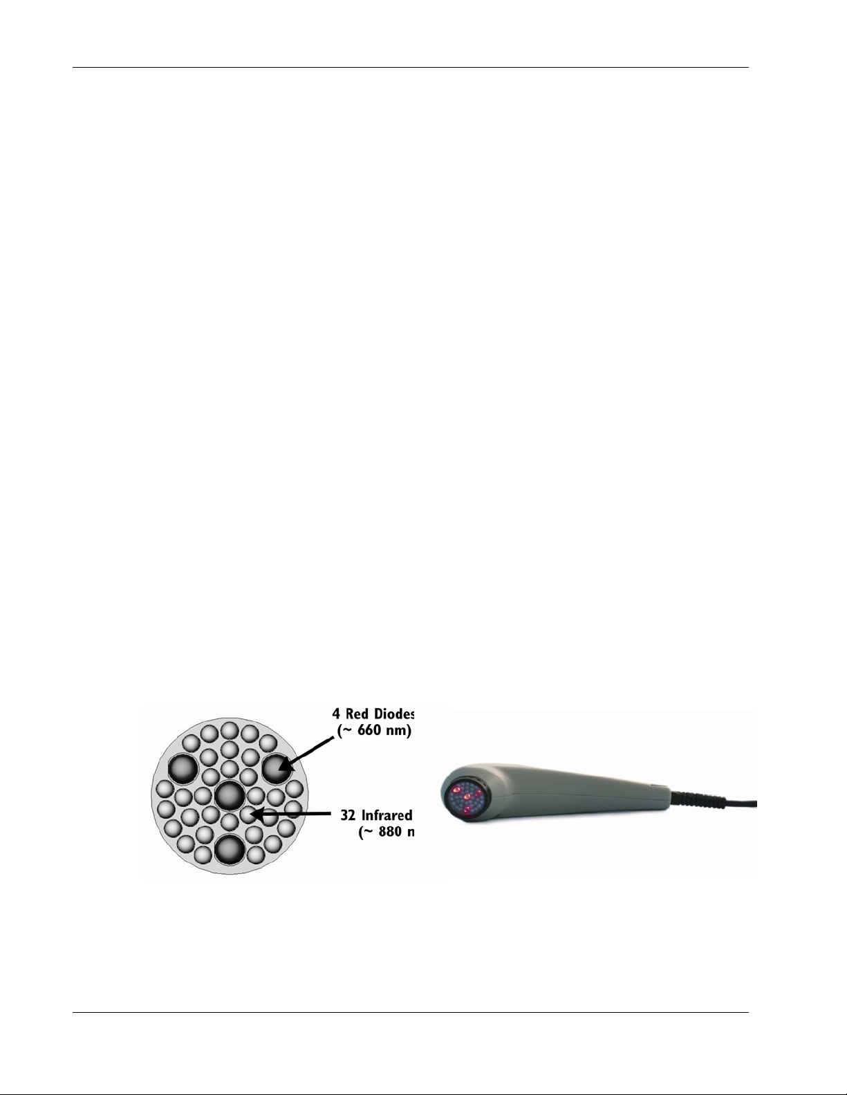
Dynatron Solaris® 700 Series
Infrared Light Therapy
Modality Information
The Solaris Infrared Light Therapy Probes and the Dynatron Xp Pad have been cleared by the FDA to
provide topical heating for temporary increase in blood circulation, temporary relief of minor muscle
and joint aches, pain and stiffness and relaxation of muscles; for muscle spasms and minor pain and
stiffness associated with arthritis.
Infrared Light Therapy Basic Vocabulary
• Continuous Wave (CW) = Light is continuously on, not pulsed
• Watts (W) = Energy (1 Joule) per second
• Milliwatt (mW) = One thousandth of a watt. Power determines length of treatment.
• Nanometer (nm) = One billionth of a meter. Wavelength determines depth of
penetration.
• Joule(s) = Watts X seconds = total energy delivered
• Dose (per cm
time.
2
) = (J/ cm
Solaris Light Therapy Probes & Dynatron Xp Pad Specifications
Following are the General Specifications for each of the Solaris probes, Xp Pad and Booster Box.
Other ranges, accuracy and precision values that are not provided here may be obtained from
Dynatronics upon request.
Solaris D880 Infrared Cluster Probe
The Dynatron 880 Infrared Cluster Probe is designed with 32 infrared Super Luminous Diodes
(SLDs) emitting a wavelength of 880nm and 4 red diodes emitting a wavelength of 660nm.
D880 Infrared Cluster Probe Specifications
Light Source: 32 Super Luminous 880 nm Diodes
4 Red 660nm Diodes
Wavelengths: Infrared Diodes – 880nm
Red Diodes – 660nm
2)
- Total energy delivered per square cm in a set period of
INFRARED LIGHT THERAPY - Treatment Instructions
78

Dynatron Solaris® 700 Series
Duty Cycles: CW, 90%, 50%, 10%
Power Output: 500mW (+/- 20%)
Dose: 6 J/cm
Solaris D890 Light Therapy Probe
2
(1 min. treatment)
The Solaris D890 Therapy Probe incorporates one laser diode emitting a wavelength of 875 nm
and 3 red diodes emitting a wavelength of 660nm.
3 Red Diodes
(~660 nm)
1 Infrared Diode Laser
(~875 nm)
Note: Probe head above shown
without opaque lens covering.
D890 Probe Specifications
Laser Source: 1 Watt Laser Diode
Red Light Source: 3 Red 660 nm Diodes
Wavelengths: Infrared Laser Diode – 875nm
Red Diodes – 660nm
Duty Cycles: CW
Power Output: 625mW (+/- 20%)
Dose: 6 J/cm
2
(48 sec.)
Imbedded Laser: 1 W 875nm CW un-collimated
Solaris D880 Plus Light Therapy Probe
The Solaris D880 Plus Infrared Cluster Probe is
similar to the D880 probe with 32 infrared super
luminous diodes emitting a wavelength of 880nm
and 4 red diodes emitting a wavelength of 660nm.
The difference lies in the power with which the light
is delivered. The D880 plus probe has a maximum
power output of 1000 mW compared to the
maximum output power of the D880 probe of 500
mW, thus reducing total treatment time.
D880 Plus Probe Specifications
The diodes for the D880 Plus will be arranged exactly as the current D880 diodes.
The D880 Plus specification will be as follows:
Infrared Diodes 32 Infrared Diodes
Red Source: 4 Red Diodes
Wavelengths: Infrared Diode – 800nm
Red Diodes – 660nm
Duty Cycles: CW – 90%, 50%, 10%
Power Output: 1W (1,000 mW) (+/- 30%)
2
Dose: 6 J/cm
(30 sec. treatment)
4 Red Diodes
(~ 660 nm)
32 Infrared SLD's
(~ 880 nm)
Treatment Instructions – INFRARED LIGHT THERAPY
79

Dynatron Solaris® 700 Series
Solaris D405 Infrared/Blue Light Probe
WARNING: Exposure to Blue Light poses an optical risk. Protective eyewear is therefore
required when using the D405 probe.
The D405 Blue/Infrared Light Probe is a
combination of Blue Light and Infrared Light
designed with 28 Blue diodes emitting a wavelength
28 Blue Diodes
(~ 405 nm)
of 405nm and 8 Infrared diodes emitting a wavelength
of 880 nm.
D405 Probe Specifications
Blue Light Source: 28 Blue Diodes
Infrared Light Source: 8 Infrared Diodes
8 Infrared Diodes
(~ 880 nm)
Wavelengths: Blue Diode – 405nm
Infrared Diode – 880nm
Duty Cycle: CW
Power Output: 500mW (+/- 30%)
2
Dose: 6 J/cm
(1 min. treatment)
Dynatron Xp Infrared Light Pad (Patent Pending)
This innovative light pad consists of 200 infrared diodes
generating 7500mW of power. The large 8”X10” flexible
design of the pad makes it possible to treat any part of the
body.
Dynatron Xp Pad Specifications
Light Source: 200 Infrared Diodes
Wavelengths: Infrared Diode – 880nm
Duty Cycle: CW
2
Power Density: 15mW/cm
Power Output: 7500mW (+/- 30%)
Dose: 8 J/cm
Dynatron Booster Box (Patent Pending)
The Dynatron Booster Box is used in conjunction with all Solaris 700 Series devises to provide
the power necessary to operate the Dynatron Xp Light Pad.
Solaris Booster Box Specifications
Power Requirements: 100-240 V~, 50/60 Hz
Output current: 2 amps (+/- 10%)
Power Consumption: 1.6 amps maximum
Fuse: 250 V, T1.6 AL slow blow
Dimensions: 14.32” W (36.37 cm) x 2.38” H (6 cm) x 12.7” D (32.26 cm)
Weight: 5.05 pounds (2.3 Kg)
2
(9.01 min. treatment)
INFRARED LIGHT THERAPY - Treatment Instructions
80

Dynatron Solaris® 700 Series
Infrared Light Therapy Probe Overlays
Dynatron Solaris Probes can be identified by either the part number located on the serial
number label, or by the color of the overlay on the probe handle. Following are the
identifying part numbers and overlay colors associated with each probe.
• D880 Black • D405 Blue
• D890 Green • D880+ Black & Gray
Infrared Light Therapy Probe/Pad Default Settings
The following default settings are set by the manufacturer and are selected when you choose
a LIGHT THERAPY PROBE or PAD treatment. You may change these defaults to your
own preferred settings. See “Setting Defaults” in this manual.
D880
• Dosage: 6 J/cm
2
(1 min. treatment)
• Duty Cycle: CW (Continuous)
D890
• Dosage: 6 J/cm
2
(48 sec. treatment)
• Duty Cycle: CW (Continuous)
D880 Plus
• Dosage: 6 J/cm
2
(30 sec. treatment)
• Duty Cycle: CW (Continuous)
D405
• Dosage: 6 J/cm
2
(1 min. treatment)
• Duty Cycle: CW (Continuous)
Dynatron Xp Pad
• Dosage: 8 J/cm
• Duty Cycle: CW (Continuous)
2
(9.01 min. treatment)
Treatment Instructions – INFRARED LIGHT THERAPY
81

Dynatron Solaris® 700 Series
Ultrasound Instructions
The following Ultrasound Instructions are for Solaris 701, 708 and 709 USERS ONLY.
The Dynatron Solaris 705 and 706 do not offer the Ultrasound feature.
Ultrasound therapy channels sound waves through muscle, nerve, bone, and connective tissue
to aid in reducing pain, muscle spasms, and joint contractures.
The physiological effect of Ultrasound therapy depends upon the frequency of the Ultrasound
signal. The lower frequency (1 MHz) penetrates deeper than a higher frequency (such as 2
MHz or 3 MHz), thus the practitioner can decide which frequency to use according to the
condition and depth to be treated.
A section in this manual entitled “Ultrasound Usage Cautions
guidelines for Ultrasound treatment and selection of the appropriate soundhead to help ensure
you deliver safe and effective treatments to your patients. Further information about
Ultrasound application may be obtained from published medical literature.
CAUTION
The Ultrasound Probe Holder was not designed to be used as a handle, to lift or carry the machine.
WARNING
” provides some general
• ALWAYS keep the applicator soundhead in constant motion.
• ALWAYS keep the soundhead properly coupled to the patient’s skin or submerged
underwater when intensity is turned on.
• Use ample conductive gel to ensure good coupling throughout the treatment. If needed,
apply additional gel during the treatment.
• See the section of this manual entitled “Contraindications, Warnings, and Precautions” for
Ultrasound treatments.
• Be alert for any sign of periosteal (bone) pain.
• Be sure to read all instructions for operation before treating a patient.
• Do not drop the soundhead on hard surfaces. Do not cool the soundhead with ice water or
ice packs. Do not allow the soundhead to overheat repeatedly. Do not hold the soundhead
in the air while a treatment is running. All of these conditions are likely to damage the
soundhead crystal and/or to stress electronic components in the device. Damage caused
by these conditions is not covered by warranty.
• CAUTION: Use of controls or adjustments or performance of procedures other than those
specified herein may result in hazardous exposure to ultrasonic energy.
Make sure a soundhead is firmly plugged into the device before turning the device on. When
changing to a different size soundhead, turn the machine off first, remove the soundhead,
plug in the desired soundhead, then turn the machine on again. Please acquaint yourself
with the following terms and device features prior to delivering an ultrasound
treatment.
ULTRASOUND - Treatment Instructions
82

Dynatron Solaris® 700 Series
Soundhead Warming
When the device is powered on, it automatically enters a default head warming mode.
During this mode the soundhead should remain in its holder as a small amount of Ultrasound
output is emitted from the soundhead (0.1 Wcm
automatically as needed to maintain a comfortable soundhead temperature. The soundhead
warming mode is automatically stopped during a treatment, and resumes automatically as
needed after a treatment has ended.
Turn Soundhead Warming Off / On
If you do not wish to use the head warming feature, you can turn the feature OFF. The head
warming setting you change to is saved and will apply to the device whenever it is used until
you change the setting again. These key presses are only necessary if you want to change the
current state of head warming.
• Press and hold the FUNCTION key and the SOUND key simultaneously to turn
soundhead warming OFF or to turn it ON again. The device will beep and the TIME
display will show the selection made as follows:
HD 1 = Head warming ON
HD 0 = Head warming OFF
• Press STOP after selecting the desired setting.
Coupling
The term “coupling” refers to the ability to deliver ultrasonic waves from the soundhead to
the skin surface with as little impedance or dissipation of power as possible. Coupling
(contact between the soundhead and the treatment site) may be provided either via a coupling
agent such as a gel or lotion. Any material used as a coupling agent must be highly
conductive of ultrasonic waves. Air is a very poor conductor of ultrasonic waves. If any part
of the soundhead is exposed to air during the treatment, coupling is decreased. The air
bubbles in a whirlpool, for example, can decrease the effective Ultrasound therapy to the
patient. Therefore, avoid allowing any air between the soundhead and the treatment area, as
with underwater treatments. Water is an excellent conductor of ultrasonic waves. Therefore,
Ultrasound treatment in water provides excellent coupling.
During the treatment the soundhead should be moved continuously covering an area
approximately twice the size of the soundhead. The full surface of the soundhead should
maintain contact with the patient’s skin (except with underwater treatments). Do not hold the
soundhead in the air while a treatment is running as this may damage the soundhead crystal
and/or stress electronic components in the device.
Patient Coupling Display
Patient Coupling is an optional display. It may be turned ON by holding down the SOUND
key and pressing the TARGET key during an Ultrasound treatment setup. As Patient
Coupling is an optional display, it must be activated with each Ultrasound treatment, or
whenever use of the display is desired.
The patient coupling display senses the coupling between the soundhead and the patient to
ensure proper delivery of the Ultrasonic therapy. The CONDUCTANCE graph illustrated
below provides a graphical representation of patient coupling during a treatment. NOTE:
Poor coupling will cause the temperature of the soundhead to increase.
2
). The warming feature turns on and off
83
Treatment Instructions – ULTRASOUND
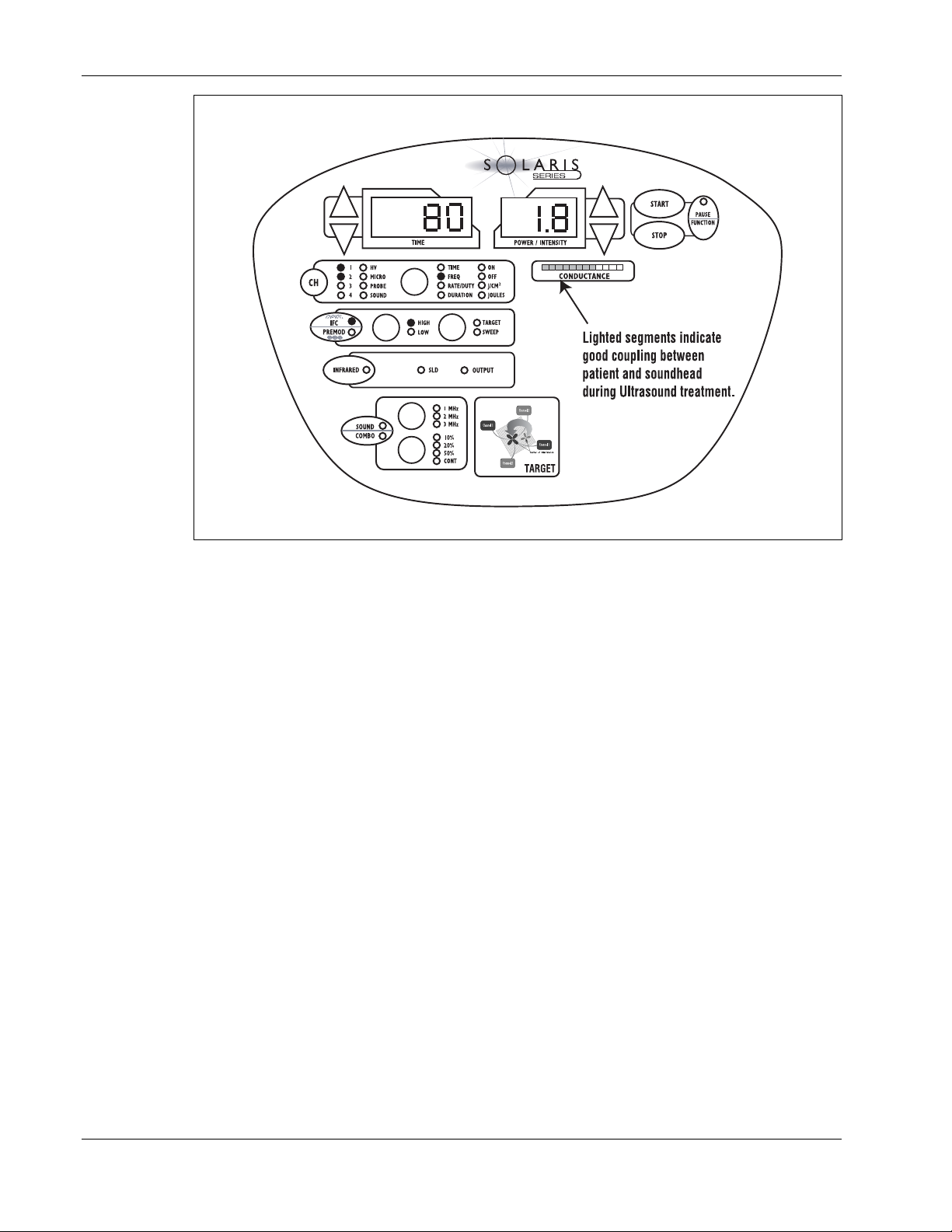
Dynatron Solaris® 700 Series
Coupling Bar Graph
Ultrasound Coupling Bar Graph
When the Patient Coupling display feature is operational, it will indicate whether adequate
contact is being maintained between the soundhead and the patient’s skin using the
COUPLING BAR GRAPH. The COUPLING BAR GRAPH is located directly under the
POWER/INTENSITY display. The bar graph displays twelve segments with twelve lighted
GREEN segments indicating best conductance, and one lighted segment indicating poorest
conductance. As conductance decreases, the number of GREEN lighted segments also
decreases. If the lighted segments continue to drop, pause the treatment and correct the
coupling error.
To correct poor coupling ensure that you are using an adequate amount of Ultrasound
conductive gel, and the face of the soundhead is making full contact with the patient’s skin.
Note: In the illustration on the previous page, eight of the twelve segments are lighted
indicating good coupling.
Head Temperature Hot Display
Ultrasound Head Temperature is another optional display that may be used when treating
with Ultrasound. To activate this feature, hold down the SOUND key then press the
HIGH/LOW key located next to IFC/PREMOD. As Head Temperature is an optional display,
it must be activated with each Ultrasound treatment, or whenever use of the display is
desired.
If coupling (the effective degree to which the Ultrasound energy is delivered from the
soundhead to the patient’s body) is not adequate during treatment, the temperature of the
soundhead rises and the patient does not receive the full intended dosage. The Dynatron
ULTRASOUND - Treatment Instructions
84

Solaris CONDUCTANCE graph displays conductance to ensure that the patient is
receiving the optimal treatment and that the soundhead crystal is protected from
overheating.
• When the coupling is acceptable, all segment lights on the coupling graph are GREEN.
• If the soundhead approaches a temperature of 103 degrees Fahrenheit, the GREEN
segments begin to be replaced by CLEAR segments, and the POWER display begins to
flash to notify the user to improve the coupling or reduce the power to prevent the
soundhead from becoming too hot.
• If the soundhead temperature
approaches the maximum
level of 108 degrees
Fahrenheit, the
POWER/INTENSITY
display reads HOT and the
treatment is automatically
PAUSED. With the output
power stopped, the treatment
time stops counting down, and
both the TIME and POWER
displays flash continuously.
NOTE: If the soundhead becomes
too hot while you are viewing treatment parameters for another output channel, the device
will automatically switch to display of the ULTRASOUND treatment and will display the
CONDUCTANCE GRAPH.
The soundhead must then be cooled down before the treatment can resume. When the
soundhead cools sufficiently, the power display and the lights on the soundhead will cease
flashing. Press PAUSE or START to resume the treatment. The soundhead will cool slowly
if placed in the soundhead holder or if held exposed to the air. Larger soundheads take longer
to cool than smaller heads. To resume the treatment right away, you can place the soundhead
in cool/room temperature water to cool the head more quickly.
NEVER USE ICE OR ICE PACKS TO COOL THE SOUNDHEADS as this is
likely to cause thermal shock to the electronic components of the soundhead and may necessitate
a costly repair. Heads damaged by thermal shock are not covered by the warranty.
When the temperature is again satisfactory, press the START key to resume the treatment. The
output power resumes, the displays return to their normal state, and the timer resumes. While
the soundhead is still too HOT, the device will not allow you to resume the treatment.
To prevent overheating of the soundhead, maintain good coupling throughout the treatment.
For direct coupling, you may need to apply more conductive gel or lotion during the
treatment to achieve better coupling.
You can reduce the power during the treatment if you are treating an area where it is difficult
to obtain good coupling.
Display Watts or W/cm
Power for the Dynatron Solaris may be displayed as WATTS or W/cm
for power is W/cm
treatment.
Dynatron Solaris® 700 Series
“HOT” Error: During an Ultrasound treatment, if the
soundhead becomes too hot, the “HOT” error message is
displayed and the treatment is paused to allow the
soundhead to be cooled.
2
2
2
, but you may select the display you prefer at any time before or during a
. The default setting
85
Treatment Instructions – ULTRASOUND

• To change the power display, press the PAUSE/FUNCTION key and hold it down
for two seconds. To change back, again press and hold the PAUSE/FUNCTION key
for two seconds.
The device will beep to indicate
you have changed the display.
Note that if you are in a
treatment when you press and
hold the Pause key, the treatment
may be paused (the Pause LED is
on) and you should press Pause
briefly again to turn off the Pause
LED and resume the treatment.
• The default power display is
2
W/cm
. If you change the
display to WATTS during use,
the machine reverts to the W/cm
display when the machine is
turned off and on again. However, if you save Ultrasound default settings while
using the WATTS display, the WATTS display will become the default
your machine.
• You can tell when you have selected WATTS display by the decimal in the display
window.
- A steadily-lighted decimal means the power is displayed in W/cm
- A blinking decimal means the power is displayed in WATTS.
Basic Ultrasound Setup
Dynatron Solaris® 700 Series
Dynatron Solaris Power/Intensity Display. You can
view power in either W/cm
2
2
or WATTS. :
display for
2
.
Basic Ultrasound Setup
1. Press the SOUND / COMBO key once to select SOUND. Press the SOUND key for
2. Choose the FREQUENCY by pressing the SOUND FREQUENCY TOGGLE key.
3. Choose the DUTY CYCLE by pressing the SOUND DUTY CYCLE TOGGLE key.
4. Change the treatment TIME, if desired using the UP/DOWN ARROW keys.
5. Raise POWER to desired level.
6. Press START.
the D701.
7. Press STOP if you need to stop a treatment before its time has expired (stops all
currently active treatments). Use the TIME arrow keys to bring treatment time to zero
or press the FUNCTION and STOP KEY together to stop only the individual displayed
treatment.
Detailed Ultrasound Setup
1. Press the SOUND / COMBO key once on the D708, D709. Press the SOUND key on
the D701.
When you press the SOUND/COMBO key once on the D708, D709 or the SOUND key
on the D701, the SOUND LED is lighted, and the Ultrasound treatment default settings
ULTRASOUND - Treatment Instructions
86

Dynatron Solaris® 700 Series
are automatically selected. If you wish to use the default settings, increase the power to
desired treatment level, press START. If you wish to customize settings, follow steps
2-5.
2. Choose the FREQUENCY.
Press the FREQUENCY TOGGLE key one or more times to choose 1, 2, or 3 MHz. Any
one of the three frequencies may be selected with the 2 cm
2
, 5 cm2 and the 10 cm2
soundheads.
3. Choose the DUTY CYCLE.
Press the DUTY CYCLE TOGGLE key one or more times to select the desired duty
cycle. Available options include 10 percent, 20 percent, 50 percent, and Continuous duty
cycle.
4. Change the treatment TIME, if desired by using the TIME UP/DOWN ARROW keys.
5. Raise POWER.
Use the POWER-INTENSITY UP/DOWN ARROW keys to increase the power to the
desired setting. For patient safety and comfort, it is recommended that you start with .1
2
, then increase power to the desired level after the treatment begins. Valid ranges
w/cm
are from 0.1 to 2.0 w/cm
are from 0.1 to 1.0 w/cm
2
(exceptions: valid ranges when using a 10 cm2 head at 3 MHz
2).
NOTE: You may view the power display in either WATTS or W/cm2. The default
2
setting for the device is W/cm
. This option is explained in detail later in this section.
6. Press START.
When you press START the treatment timer begins counting down and output is
delivered to the soundhead. If you fail to set the power before pressing START, the
intensity display will begin flashing, and you will be unable to start the treatment until
you set the power.
Be sure to use a coupling agent such as gel or lotion, and maintain good coupling
throughout the treatment (see “Ultrasound Usage Cautions” in this manual).
Do not hold
the soundhead in the air, as this will cause the soundhead to overheat. The device
provides coupling sensing to help you know when coupling is not adequate. This feature
is discussed later in this section.
SAVE DEFAULTS. If the treatment you have just set up is the most common
Ultrasound setup you use, you can save the treatment parameters as new defaults for your
own machine. After setting up the treatment, simply press and hold the START key for
two seconds. At the end of two seconds, you will hear a beep indicating the treatment
parameters have been saved. The next time you select the SOUND modality, these
parameters are selected automatically.
7. MODIFY a treatment in progress, if desired.
While the treatment is in progress, you can modify the following treatment parameters.
• Use the FREQUENCY TOGGLE key to select a different FREQUENCY.
• Use the DUTY CYCLE TOGGLE key to select a different DUTY CYCLE,
• Use the TIME ARROW keys to increase or decrease the treatment TIME.
87
Treatment Instructions – ULTRASOUND

Dynatron Solaris® 700 Series
• Use the POWER/INTENSITY ARROW keys to increase or decrease the
INTENSITY.
• Press and hold the PAUSE/FUNCTION key for two seconds to change display from
2
w/cm
to Watts or reverse.
8. Temporarily PAUSE a treatment, if necessary, while the treatment is in progress.
To temporarily PAUSE the treatment, press the PAUSE key. This stops the Ultrasound
output from the soundhead and pauses the treatment timer without ending the treatment.
While a treatment is paused, the light on the PAUSE key is lighted and the Ultrasound
output to the soundhead is stopped. To resume the treatment, either press START or
press PAUSE again. Output then resumes and the treatment timer starts from where it
was paused.
NOTE: During a COMBO treatment, THE STIM OUTPUT OF THE
TREATMENT IS NOT PAUSED when the PAUSE key is pressed, although the
Ultrasound output is stopped and the treatment timer is paused.
9. Press STOP if you need to stop a treatment before its time has expired.
When the treatment time for a treatment has elapsed, the output to the soundhead is
stopped and a tone sounds notifying you of the treatment end.
ALL STOP: Pressing the STOP key will terminate all treatments in progress.
STOP ONE TREATMENT ONLY: If you have more than one treatment in progress,
you can stop one treatment by either of the following methods. First, press the
CHANNEL TOGGLE key to select the channel to be stopped (that channel’s light is
GREEN when selected).
FUNCTION-STOP. Press and hold the FUNCTION key and press STOP to
terminate the displayed treatment.
REDUCE THE TREATMENT TIME TO ZERO. Press the TIME DOWN
ARROW until the TIME display reaches zero. The device beeps when the time
reaches zero and the displayed treatment terminates.
The output at the selected channel is stopped, and the device then displays the parameters
for the next treatment that remains in progress (if any).
ULTRASOUND - Treatment Instructions
88

Dynatron Solaris® 700 Series
Ultrasound Modality Information
For Dynatron® Solaris™ 701, 708 and 709 users only.
The Dynatron
Ultrasound, by its very nature, has the ability to irritate the patient’s skin. While the benefits
of Ultrasound far outweigh any disadvantages, certain precautions should be observed to
assure maximum safety and comfort for your patients.
A patient’s tendency to have adverse reactions to Ultrasound is dependent upon several
factors. Some of these factors are discussed below.
Selecting the Appropriate Soundhead
®
Solaris™ 705 and 706 do not offer the Ultrasound feature.
Head and Crystal Size Comparison
The selection of the appropriate soundhead is key to the success of the treatment and is based
on the size of the area to be treated. Ultrasound treatments should be kept specific to the
tissue involved in pathology. A good guideline is 2 to 4 times the size of the soundhead. For
example:
• A 2 cm2 soundhead can deliver up to 4 Watts and is appropriate for small areas (i.e.
hands, fingers, feet).
Treatment Instructions - ULTRASOUND
89

Dynatron Solaris® 700 Series
• A 5 cm2 soundhead can deliver up to 10 Watts and is appropriate for medium sized areas
(i.e. extremities such as arms, legs and cervical areas).
• A 10 cm2 soundhead can deliver up to 20 Watts and is appropriate for large areas (i.e.
torso and back).
Ultrasound is a directed beam of energy. Therefore, not only will the average spatial
intensity be a factor in the dosage the patient receives, but the time delivered and area
covered will matter as well. For example, an area of 50 cm
an area of 200 cm
2
is treated for 5 minutes. Both receive the same intensity. The 200 cm
2
is treated for 5 minutes. Then
2
area however does not receive the same dosage (only ¼ ) because as the soundhead is moved
around the area it has to cover represents 4 times as much tissue.
The Soundhead area measurement is the ERA (effective radiating area). Each soundhead has
an effective radiating area. It is not necessarily the outside diameter of the soundhead, but the
area of the crystal inside, therefore special care should be taken in selecting the correct size
soundhead for the area to be treated according to the diameter of the crystal. See the Head
and Crystal Size Comparison graphic on the previous page.
NOTE: If a patient experiences pain during a treatment, the size of the soundhead may be inappropriate
for the area being treated, the intensity is too high or the treatment time is too long.
Penetration of Ultrasound Waves
The correct frequency should be selected for the depth of penetration desired. The amount of
penetration needed is determined by the density of tissue and the depth of the site to be
treated. Care should be taken to select a penetration level that does not cause periosteal
(bone) pain.
The frequency determines the depth of penetration of the Ultrasonic wave.
• Select 1 MHz for deep lesions;
provides a Half-Value Distance
(HVD) of about 5cm.
• Select 2 MHz for moderate
depth lesions; about 2.6cm
HVD.
• Select 3 MHz for superficial
lesions; about 1.5cm HVD.
HVD is the approximate point at
which the Ultrasound energy is
reduced to half in the average
Multi-Frequency Ultrasound
human tissue.
Types of Delivery
Ultrasound can be delivered in four different ways. You will likely only see two of the four
methods in clinical practice.
1. Direct Contact Movable: Here the soundhead is placed in direct contact with the patient.
A coupling agent is used between soundhead and the patient’s skin. The soundhead is
moved slowly, but continuously. This is the method of choice.
ULTRASOUND - Treatment Instructions
90

The rate of speed at which the applicator moves across the skin is very important in
determining how much Ultrasonic output is delivered. If the rate is too slow, the patient
may feel periosteal pain (bone ache/pain). If the rate is too fast, or if the applicator head
becomes uncoupled with the skin, the amount of treatment is reduced. Uncoupling can
also cause the soundhead to overheat.
2. Immersion Method: Here the area to be treated is placed underwater. The soundhead is
water tight so it can be immersed with the area to be treated. The water becomes the
coupling agent. The head is always moving around the surface area, but not in contact
(1/2 to 1 inch away).
3. Hydrogel Disk: For treating crater wounds, cover the wound with a hydrogel disk and
apply the soundhead to the disk. This allows direct wound sonation without bringing the
soundhead in direct contact with the wound.
4. Stationary Soundhead: This method is dangerous. Hot spots can develop. Do not use.
Treatment Time
For Sub-Acute Conditions: area to be treated (cm
1.5 x ERA
For Chronic Conditions: area to be treated (cm2) = minutes of treatment
For Maximal Thermal Effect: area to be treated (cm2) = minutes of treatment
0.8 x ERA
Treatment Intensity
Several factors come into play as one decides the level of intensity for the treatment.
1. Superficial lesions require less intensity.
2. Less intensity should be used if bone is superficial to the treatment field.
3. Less intensity should be used when the stage of the injury makes heating questionable.
4. Use a little lower intensity for the first treatment to gauge response.
5. Patient feedback is key. A treatment should feel warm, but the patient should never feel
heat, pain, stabbing, pricking or dull ache.
Acute Conditions: 0.1 – 0.5 W/cm2 (no appreciable thermal effect).
Sub-Acute Conditions: 0.5 – 1.0 W/cm
Chronic Conditions: 1.0 – 2.0 W/cm
NOTE: It is very common that intensity is always 1.5 W/cm2. This is incorrect in many
cases. A more specific intensity should be used based on patient response and stage of injury.
Frequency of Treatment
Treatment can be given daily. It is not uncommon to give Ultrasound twice daily, but this
may be excessive. Some guidelines may be helpful.
1. Daily may be the best maximum frequency.
2. Ultrasound can be effectively given every other day.
3. Ultrasound should give some positive benefits by the 3
discontinue the treatment and consider other options.
Dynatron Solaris® 700 Series
1.0 x ERA
2
(Mild to Moderate thermal effect).
2
(Moderate to Strong thermal effect).
Treatment Instructions - ULTRASOUND
91
2
) = minutes of treatment
rd
or 4th application. If not,

Dynatron Solaris® 700 Series
4. A maximum of 12 to 15 Ultrasound treatments should be given. If the result desired has
not been reached by this point, Ultrasound may not be the proper choice.
EXCEPTION: Some Chronic conditions which cause adhesions.
Usage Cautions – Combination Treatments
When using a Stim device in conjunction with a Solaris Device to output Stim through the
soundhead, observe all contraindication, warnings, precautions and usage cautions provided
by the manufacturer for all modalities involved.
Potential for Burns or Periosteal Pain
Some patients’ skin is more sensitive to Ultrasound output. This can cause a reaction similar
to a heat rash. It is also possible for a patient to suffer a burn from Ultrasound therapy if the
therapy is not administered properly. This can occur for the following reasons:
• Intensity (power) too high
• Frequency too low
• Holding the soundhead in one place on the patient’s skin
• Moving the soundhead too slowly
• Treating an area where sensory nerve damage is present with a loss of normal skin
sensation
• Time (Caution: Don’t treat too long).
Bony prominences are especially susceptible, as they reflect sound waves and increase
intensity to the periosteum resulting in a burning sensation. Desensitized areas can be
overheated or burned without the patient realizing it, so extreme
these patients (e.g. diabetes, neural damage, etc.)
Burns can be avoided as long as the treatment causes no pain, tingling, excess heat or aching
(for patients with normal skin sensation). Use sufficient coupling agent and make sure there
are no bubbles in the gel. When treating in water, clear the bubbles off the soundhead and off
the patient’s skin.
An un-calibrated unit can also cause tingling, excess heat, aching, or a burning sensation.
Read Ultrasound Contraindication, Warning, & Precaution in this manual for more information.
Soundhead Optimization (D701, D708, D709)
Adding or Replacing Soundheads
To ensure soundhead output is optimized, please carefully follow the instructions provided.
The procedure utilizes keys and displays on the key pad that are normally used for other
purposes, but which have specialized applications in the Head Parameters Mode. If you have
any questions about the following instructions, contact Dynatronics’ Customer Service
Department before proceeding (800) 874-6251).
1. Head Calibration Printout. Soundhead models are shipped with a Head Calibration
Printout sheet. On the following page is an example of this sheet. The sheet contains
unique calibration numbers for a specific soundhead. The soundhead serial number
appears on the sheet to assist you in matching the correct soundhead with the printed
parameters.
care must be taken with
ULTRASOUND - Treatment Instructions
92
 Loading...