


SERVICE MANUAL
Dynatron® 850plus &
Dynatron® 550plus
i

Dynatron® 850plus & 550plus
CAUTION: Federal law restricts this device to sale by or on the order of a physician, chiropractor, physical therapist, or dentist licensed by the law of the state in which said person practices to use or order the use of the device.
IMPORTANT: Before treating a patient with the Dynatron 850plus or the Dynatron 550plus, see the “Contraindications, Warnings, and Precautions” in this manual.
INDICATIONS FOR USE:
Muscle stimulation therapy delivered by the Dynatron 850plus and 550plus is indicated for the following uses:
1.relaxation of muscle spasm;
2.prevention or retardation of disuse atrophy;
3.increasing local blood circulation;
4.muscle re-education;
5.immediate postsurgical stimulation of calf muscles to prevent venous thrombosis; and
6.maintaining or increasing range of motion.
Interferential, premodulated, high volt, and microcurrent therapy are indicated for providing temporary relief of chronic intractable pain.
INDICATIONS FOR ULTRASOUND USE:
Ultrasound therapy is intended to generate deep heat within body tissues for the treatment of selected medical conditions such as relief of pain, muscle spasms, and joint contractures, but not for the treatment of malignancies.
(21 CFR 890.5300)
Dynatron® 850plus and Dynatron® 550plus Service Manual
Revised June 2004
© Copyright 1997
Dynatronics Corporation
7030 Park Centre Drive
Salt Lake City, UT 84121 (801) 568-7000 (800) 874-6251
ALL RIGHTS RESERVED
ii

Dynatron® 850plus & 550plus
Table of Contents |
|
Section I |
|
Introduction I |
|
Introduction to the Dynatron 850plus™ and 550plus™ ........................................................................ |
2 |
New Features.......................................................................................................................................... |
2 |
Treatment Options.................................................................................................................................. |
3 |
Simplified Setup ..................................................................................................................................... |
4 |
Before You Treat a Patient ..................................................................................................................... |
4 |
How to Use This Manual........................................................................................................................ |
4 |
Installation and Features............................................................................................................................ |
5 |
Unpacking .............................................................................................................................................. |
5 |
Standard Accessories.............................................................................................................................. |
5 |
Soundheads and Probes .......................................................................................................................... |
6 |
Accessories............................................................................................................................................. |
6 |
Dynatron 850plus and Dynatron 550plus Physical Features.................................................................. |
7 |
Instructions for Using Toggle Keys ..................................................................................................... |
13 |
Time and Power Displays..................................................................................................................... |
15 |
Ultrasound Heads (Dynatron 850plus only)......................................................................................... |
15 |
Microcurrent Probes (optional accessory)............................................................................................ |
16 |
High Volt Probe (optional accessory) .................................................................................................. |
17 |
Quick Reference of Special Key Presses ................................................................................................. |
18 |
Section II |
|
Operation and Treatment Instructions |
|
General Operating Instructions............................................................................................................... |
20 |
Power On/Off ....................................................................................................................................... |
20 |
Basic Treatment Setup.......................................................................................................................... |
20 |
Conductance Bar Graph ....................................................................................................................... |
21 |
“LEAD” Warning - No Patient Current ............................................................................................... |
22 |
Interferential / Premodulated Instructions............................................................................................. |
24 |
Basic Interferential / Premod Setup...................................................................................................... |
24 |
Detailed Interferential / Premodulated Setup ....................................................................................... |
25 |
Interferential / Premodulated Default Settings ..................................................................................... |
28 |
iii

Dynatron® 850plus & 550plus
Biphasic / Russian Instructions ................................................................................................................ |
29 |
Basic Biphasic / Russian Setup............................................................................................................. |
30 |
Detailed Biphasic / Russian Setup ........................................................................................................ |
30 |
Biphasic / Russian Default Settings ...................................................................................................... |
33 |
High Volt Instructions............................................................................................................................... |
35 |
Set Up High Volt Treatment with Electrodes ....................................................................................... |
35 |
Set Up High Volt Treatment with Optional Probe................................................................................ |
36 |
Basic High Volt Setup .......................................................................................................................... |
37 |
Detailed High Volt Setup...................................................................................................................... |
37 |
High Volt Default Settings.................................................................................................................... |
41 |
Microcurrent Instructions ........................................................................................................................ |
42 |
Basic Microcurrent Setup ..................................................................................................................... |
42 |
Microcurrent Treatment Time............................................................................................................... |
43 |
Detailed Microcurrent Setup................................................................................................................. |
43 |
Audio Tone ........................................................................................................................................... |
46 |
Microcurrent Default Settings............................................................................................................... |
46 |
How To Use Microcurrent Probes ........................................................................................................ |
46 |
Ultrasound Instructions ............................................................................................................................ |
48 |
Soundhead Warming............................................................................................................................. |
48 |
Turn Soundhead Warming Off / On ..................................................................................................... |
49 |
Basic Ultrasound Setup......................................................................................................................... |
49 |
Detailed Ultrasound Setup .................................................................................................................... |
49 |
Ultrasound Default Settings.................................................................................................................. |
51 |
Patient Coupling ................................................................................................................................... |
51 |
Poor Coupling ....................................................................................................................................... |
52 |
Ultrasound Coupling Bar Graph ........................................................................................................... |
52 |
Head Temperature Hot.......................................................................................................................... |
53 |
Head Temperature Bar Graph ............................................................................................................... |
54 |
Display Watts or W/cm2....................................................................................................................... |
54 |
Combination Therapy Instructions ......................................................................................................... |
56 |
Comboplus™ ........................................................................................................................................ |
56 |
Stim Through the Soundhead................................................................................................................ |
57 |
Combination Therapy Setup ................................................................................................................. |
58 |
Modify Treatment ................................................................................................................................. |
60 |
Combination Default Settings............................................................................................................... |
61 |
iv

Dynatron® 850plus & 550plus
Simultaneous Treatments......................................................................................................................... |
62 |
Set Up A Second Treatment ................................................................................................................. |
62 |
Modify Simultaneous Treatments ........................................................................................................ |
63 |
Stop One Treatment.............................................................................................................................. |
63 |
Setting Defaults ......................................................................................................................................... |
64 |
Save New Defaults ............................................................................................................................... |
64 |
Restore Factory Defaults ...................................................................................................................... |
65 |
Interferential Default Settings .............................................................................................................. |
65 |
Premodulated Default Settings ............................................................................................................. |
65 |
Russian / Biphasic Default Settings ..................................................................................................... |
65 |
High Volt Default Settings ................................................................................................................... |
66 |
Microcurrent Default Settings .............................................................................................................. |
66 |
Ultrasound Default Settings ................................................................................................................. |
66 |
Combination Default Settings .............................................................................................................. |
66 |
Battery Operation ..................................................................................................................................... |
67 |
Battery Requirements ........................................................................................................................... |
68 |
Battery Life........................................................................................................................................... |
68 |
Section III |
|
General Modality Information |
|
Interferential and Premodulated Therapy ............................................................................................. |
70 |
Interferential (Quadpolar) Therapy ...................................................................................................... |
70 |
Premodulated (Bipolar) Therapy.......................................................................................................... |
70 |
Target.................................................................................................................................................... |
71 |
Why Is Target Better? .......................................................................................................................... |
71 |
Sweep ................................................................................................................................................... |
72 |
Interferential Electrode Placement ....................................................................................................... |
72 |
Russian / Biphasic Therapy...................................................................................................................... |
73 |
Russian Stimulation.............................................................................................................................. |
73 |
Biphasic Stimulation ............................................................................................................................ |
73 |
Biphasic / Russian Parameters.............................................................................................................. |
73 |
High Volt Therapy .................................................................................................................................... |
76 |
High Volt Therapy with Electrodes...................................................................................................... |
76 |
High Volt with Optional Probes........................................................................................................... |
76 |
High Volt Waveform............................................................................................................................ |
76 |
High Volt Settings ................................................................................................................................ |
76 |
v

Dynatron® 850plus & 550plus
Microcurrent Therapy .............................................................................................................................. |
78 |
Microcurrent Therapy with Electrodes ................................................................................................. |
78 |
Microcurrent Therapy with Probes ....................................................................................................... |
78 |
Microcurrent Waveforms...................................................................................................................... |
78 |
Microcurrent Settings............................................................................................................................ |
78 |
Ultrasound Therapy .................................................................................................................................. |
79 |
About Ultrasound.................................................................................................................................. |
79 |
SmartHeads ........................................................................................................................................... |
79 |
Patient Coupling ................................................................................................................................... |
79 |
Soundhead Temperature ....................................................................................................................... |
80 |
Section IV |
|
Contraindications, Warnings, and Precautions |
|
Contraindications, Warnings, & Precautions for Interferential, Premodulated, Russian, Biphasic, and |
|
High Voltage Pulsed Stimulation ............................................................................................................. |
82 |
Contraindications .................................................................................................................................. |
82 |
Warnings............................................................................................................................................... |
82 |
Precautions............................................................................................................................................ |
83 |
Treatment Setup Warnings ................................................................................................................... |
84 |
Adverse Effects..................................................................................................................................... |
84 |
Use Only Dynatronics Accessories With This Device ......................................................................... |
84 |
Contraindications, Warnings, & Precautions for Microcurrent Treatment........................................ |
85 |
Indications for Use................................................................................................................................ |
85 |
Contraindications .................................................................................................................................. |
85 |
Warnings............................................................................................................................................... |
85 |
Precautions............................................................................................................................................ |
86 |
Adverse Reactions ................................................................................................................................ |
86 |
Contraindications, Warnings, & Precautions for Ultrasound Treatment ........................................... |
87 |
Contraindications .................................................................................................................................. |
87 |
Precautions............................................................................................................................................ |
88 |
Warnings............................................................................................................................................... |
88 |
Electrotherapy Usage Cautions................................................................................................................ |
89 |
Carbon Electrodes................................................................................................................................. |
90 |
Self-Adhesive Electrodes...................................................................................................................... |
91 |
Combination Treatment Usage Cautions .............................................................................................. |
92 |
Lead Wires ............................................................................................................................................ |
92 |
Test Leads ............................................................................................................................................. |
93 |
vi

Dynatron® 850plus & 550plus
Current Limit........................................................................................................................................ |
93 |
Current Limit Warning......................................................................................................................... |
94 |
Microcurrent Usage Cautions.................................................................................................................. |
95 |
Ultrasound Usage Cautions...................................................................................................................... |
96 |
Applicator Movement........................................................................................................................... |
96 |
Patient Susceptibility............................................................................................................................ |
96 |
Potential for Burns................................................................................................................................ |
96 |
Output Power........................................................................................................................................ |
97 |
Penetration of Ultrasound Waves......................................................................................................... |
97 |
Coupling ............................................................................................................................................... |
97 |
Section V |
|
Ultrasound Technical Information |
|
Ultrasound Regulation............................................................................................................................ |
100 |
Beam Profile ............................................................................................................................................ |
101 |
Enter Soundhead Parameters ................................................................................................................ |
104 |
New SmartHeads™ ............................................................................................................................ |
104 |
Using Older Model Soundheads With the 50 Series Plus .................................................................. |
104 |
Calibration Procedure ............................................................................................................................ |
106 |
Problem Solving ...................................................................................................................................... |
109 |
Soundhead Temperature Too Hot ...................................................................................................... |
109 |
Cooling the Soundhead ...................................................................................................................... |
109 |
Whirlpool Treatments......................................................................................................................... |
109 |
Soundhead Temperature Too Cold..................................................................................................... |
110 |
No Soundhead .................................................................................................................................... |
110 |
Other Error Messages in the Display.................................................................................................. |
110 |
Section VI |
|
Technical Information |
|
General Specifications ............................................................................................................................ |
114 |
Dynatron 850plus and 550plus Specifications ................................................................................... |
114 |
Stim Specifications............................................................................................................................. |
114 |
Microcurrent Specifications ............................................................................................................... |
114 |
High Volt Specifications .................................................................................................................... |
115 |
Ultrasound Specifications (Dynatron 850plus only) .......................................................................... |
115 |
vii

Dynatron® 850plus & 550plus
Environmental Conditions .................................................................................................................. |
115 |
Safety Features of the Dynatron 850plus and 550plus ....................................................................... |
115 |
Care and Cleaning Instructions........................................................................................................... |
116 |
Suggested Maintenance Schedule....................................................................................................... |
116 |
Routine Ultrasound Calibration Inspections (Dynatron 850plus only)............................................... |
117 |
Software Updates ................................................................................................................................ |
118 |
Returning a Unit for Repair ................................................................................................................ |
118 |
Definition of Symbols......................................................................................................................... |
119 |
Equipment Classification .................................................................................................................... |
119 |
Disposal of Equipment and Accessories............................................................................................. |
119 |
Additional Technical Information Available (for Technicians Only)................................................. |
120 |
FDA Compliant Electrodes and Lead Wires....................................................................................... |
120 |
Medical Device Reporting Requirements.............................................................................................. |
121 |
Reporting any Incident of Patient Discomfort .................................................................................... |
121 |
Section VII |
|
Service |
|
Processor Interaction .............................................................................................................................. |
124 |
Processor Interaction with the Keyboard and Displays ...................................................................... |
124 |
Processor Interaction with Oscillators ................................................................................................ |
124 |
Processor Interaction with the Output Jacks ....................................................................................... |
124 |
Processor Control of Output Waveforms............................................................................................ |
124 |
Basic Trouble Shooting Techniques....................................................................................................... |
125 |
Hands-On Testing Pads and Leads ..................................................................................................... |
125 |
Installing Software Updates.................................................................................................................... |
126 |
Installing Replacement Parts.................................................................................................................. |
126 |
Section VIII |
|
Schematics and QC Check Lists |
|
viii

Dynatron® 850plus & 550plus
Section I
Introduction
1

Dynatron® 850plus & 550plus
Introduction to the Dynatron 850plus™ and 550plus™
The Dynatron 850plus and Dynatron 550plus offer the practitioner a wide range of treatment options in a single device. Both devices provide interferential and premodulated therapy, high voltage pulsed stimulation, Russian and biphasic stimulation, and microcurrent. The 850plus also includes ultrasound and combination therapy.
The devices include the advantages of earlier Dynatronics models, such as customizable treatments with convenient setup. In addition, these units are smaller and lighter in weight than earlier models and now offer the option of battery operation, making the devices truly portable. One additional channel is now dedicated to high volt therapy, allowing a greater variety of simultaneous treatments. The manufacturer’s warranty for these devices is now two years (see full warranty details at the back of this manual).
This manual provides operator information and instructions for both of these models. The sections that discuss ultrasound and combination treatments apply only to the Dynatron 850plus model. All other sections of this manual apply to both devices. Sections of this manual that apply only to the Dynatron 850plus are clearly marked.
New Features
For models having software greater than Rev. 1.01 or later, the following new features have been added (effective January 1998).
•Conductance Bar Graph. A graphical representation of conductivity during and interferential, premodulated, or microcurrent treatment.
•Ultrasound Coupling Bar Graph. Shows soundhead coupling during an ultrasound treatment.
•Soundhead Temperature Bar Graph. Indicates when soundhead temperature is too hot during a treatment.
•“Lead” warning. A new warning displayed if the device detects an open circuit, indicating no patient current is being delivered and the treatment setup must be inspected.
•New warnings notifying the user when the soundhead is too hot, or when the soundhead is not detected by the device
These new features are described in greater detail in the treatment instructions later in this manual. The determine the software revision level for the Dynatron device, power the device on and observe the number shown in the Time display at the end of the device’s startup routine.
Introduction
2
Dynatron® 850plus & 550plus
Treatment Options
The following modalities are provided by both the Dynatron 850plus and the Dynatron 550plus:
Interferential Therapy: This traditional therapy, delivered with two channels and four electrodes, also includes Dynatronics’ patented Target feature for easy location of the treatment site and delivery of the full interferential beat where it is needed.
You can select the high frequency range, the low frequency range, or both, along with Target. Or select Sweep when you want to deliver the current over a more general area. You can also customize the frequency settings for individual treatments or save a unique default setting.
Premodulated Therapy: Ideal for treating areas where four electrode-placement is not practical, this modality extends the versatility of the device by offering a premodulated interferential current using one channel and two electrodes.
Biphasic Stimulation: This option provides muscle stimulation using a sinusoidal biphasic waveform with pulse widths, ranging from 50 to 400 microseconds. It offers normal, co-contraction and reciprocal contraction modes, selectable on/off cycle times and ramp times, and customizable pulse rate and pulse width.
Russian Stimulation: With this modality, you can deliver muscle stimulation treatments selecting from an array of options including normal, co-contraction and reciprocal contraction, selectable on/off cycle times and ramp times, and customizable pulse rate and pulse width.
High Voltage Pulsed Stimulation: This traditional electrotherapy modality offers a pulsed, monopolar current with pulse widths in the microsecond range and pulse rates ranging from 1 to 200 Hz utilizing a twin-peak monophasic waveform. Polarity, on/off cycle time, and ramp time are selectable, and pulse rate may be customized for each treatment. Treatment may be delivered using either electrodes or optional probes.
Microcurrent Therapy: Microcurrent treatment may be delivered using two electrodes for unattended therapy, or the optional hand-held probes for manual treatment. You may select the desired polarity and customize the frequency and intensity. An audible tone allows you to monitor conductance.
The following additional modalities are provided with the Dynatron 850plus (not included with the Dynatron 550plus):
Ultrasound Therapy: The Dynatron 850plus includes Dynatronics’ patented multifrequency ultrasound capability. Soundheads are available in 1 cm2, 2 cm2, 5 cm2, and 10 cm2 sizes. Each soundhead offers 1, 2, and 3 MHz. (The 1 cm2 soundhead offers 2 and 3 MHz.) Duty cycle options are 10, 20, or 50 percent, or a continuous duty cycle.
Combination Therapy - Comboplus™: Dynatronics’ new Comboplus feature gives you almost unlimited options in setting up a combination treatment with the Dynatron 850plus. Now you can combine an ultrasound treatment with any singlechannel electrotherapy modality provided by this device, including Premodulated, Biphasic, Russian, High Volt, or Microcurrent. In addition, combination therapy is
3

Dynatron® 850plus & 550plus
no longer restricted to just one channel—any channel may be used. This means you may set up a combination treatment using any of the three electrotherapy output jacks. Combination therapy offers simultaneous treatment time and allows you to select from all the available options for both modalities used in the combined treatment.
Simplified Setup
The unique design of the Dynatron 850plus and 550plus front panels means treatment setup has never been easier. A few simple key presses are all you need to fully set up a treatment. The careful grouping of available options for each modality ensures that you can easily see and select from the appropriate options for that modality.
Each modality offers default settings which are automatically selected when the modality is selected—saving time in the treatment setup. You can change these defaults to match your own most common treatment setups to reduce setup time to a matter of seconds.
Before You Treat a Patient
Before administering a treatment to a patient with the Dynatron 850plus or 550plus, you should familiarize yourself with all the operating instructions for the modality used, as well as the contraindications, warnings, and precautions for that modality.
You should also read in this manual general information about each of the modalities. In addition to the information provided in this manual, consult other published sources for additional application and safety instructions regarding use of each type of therapy.
How to Use This Manual
This manual is organized to help you learn how to use your Dynatron 850plus and 550plus device, and to provide easy reference for looking up specific instructions or information. The information in the manual is grouped as listed below. Note that all treatment instructions for all modalities are in one section, and that all contraindications, warnings, and precautions for all modalities are provided together in another section.
This grouping of information makes it easy for you to find what you are looking for. To assist you further, descriptive titles appear at the foot of each page to help to identify immediately what section you are in. Familiarize yourself with the organization and presentation of this manual to make best use of the information provided.
Section I: Introduction, Installation and Features
Section II: Operation and Treatment Instructions
Section III: General Modality Information
Section IV: Contraindications, Warnings, and Precautions
Section V: Ultrasound Technical Information
Section VI: General Technical Information
Section VII: Patient Information
Introduction
4

Dynatron® 850plus & 550plus
Installation and Features
Unpacking
When you receive the unit, immediately unpack it and all accessories and check for possible damage, obvious or concealed. In case of damage, immediately notify the carrier and take any steps necessary to file a claim for the damage sustained. Do not destroy the shipping carton. The carton should be reused if the device must be shipped for any reason. The carton is specially designed to protect the unit from shipping damage. Improper packaging of the unit during transport can result in damage and invalidate the warranty.
Complete the warranty registration form and return it to Dynatronics within 10 days of purchase. This is essential to insure you are not billed for services that are covered by the warranty policy. Warranty registration should include serial numbers for both the device and soundheads.
Connect the AC power cord, which is equipped with a hospital grade, UL listed plug, to a properly grounded 110/120V 60 Hz AC outlet (the device will automatically switch to 220/240V 50 Hz when connected to a power source with that voltage). The power cord must also be firmly plugged into the device itself. When the cord is properly connected, it can not be easily pulled out. Do not place the cord or the device in a place where the cord could be tripped over or accidentally pulled out of its socket during a treatment.
Read the operating instructions in this manual before proceeding with a treatment.
Standard Accessories
The following accessories are included with the Dynatron 850plus or 550plus units:
Qty |
Part No. |
Description |
1 |
D851/ D551 |
Dynatron® 850plus or Dynatron® 550plus unit |
1 |
9B0031 |
Power Cord |
1 |
8A0061 |
Patient Remote Stop Cable |
1 |
8H0006 |
Operator's manual |
2 |
7B0230/ 7B0231 |
72” double leads (1 red, 1 black) |
1 |
7B0234 |
Special lead wire for combination treatments (with Dynatron |
|
|
850plus only) |
1 |
7B0204 |
POLYS™ self-adhesive electrodes 1.75” x 3.75” w/pin |
|
|
connector (pkg of 4) |
4 |
7B0063/ 7B0065 |
3” round carbon electrodes (2 red, 2 gray) |
4 |
7B0191 |
Sponge fabric for use with carbon electrodes |
2 |
DW248 |
2” x 48” straps |
1 |
7B0191 |
5” x 8” dispersive electrode for high volt w/ sponge fabric |
1 |
7B0202 |
Applications manual |
1 |
7B0217 |
Ultrasound gel sample (with Dynatron 850plus only) |
Installation & Features
5

Dynatron® 850plus & 550plus
Soundheads and Probes
The Dynatron 850plus may be purchased with one or more applicator soundheads in the following sizes:
Part No. |
Size |
Frequencies |
SH01CM |
1 cm2 |
Operates at 2 and 3 MHz |
CM02SH |
2 cm2 |
Operates at 1, 2, and 3 MHz |
CM05SH |
5 cm2 |
Operates at 1, 2, and 3 MHz |
CM10SH |
10 cm2 |
Operates at 1, 2, and 3 MHz |
An optional high volt probe or microcurrent probe may also be purchased for use with this device. Contact your Dynatronics dealer to order optional accessories
Accessories
The following optional and replacement accessories may be purchased from Dynatronics or from your Dynatronics dealer:
Part No. |
Description |
8E0026 |
High volt probe (requires one or more applicators) |
8E0017 |
High volt applicator 2” round |
8E0018 |
High volt applicator 5/8” round |
8E0019 |
High volt applicator 2”x1-1/2” |
8D0007 |
Microcurrent active probe |
8D0027 |
Microcurrent ground probe |
7B0208/ 7B0209 |
2” diameter carbon electrodes (red and gray) |
7B0063/ 7B0065 |
3” diameter carbon electrodes (red and gray) |
7B0059/ 7B0061 |
3” x 5” carbon electrodes (red and gray) |
7B0067/ 7B0069 |
1.5” x 2.0” carbon electrodes (red and gray) |
7B0003/ 7B0203 |
1.75” x 3.75” adhesive electrodes (with snap or pin connector) |
7B0005/ 7B0204 |
1.75” square adhesive electrodes (with snap or pin connector) |
7B0205 |
1.25 round adhesive electrodes (with pin connector) |
7B0206 |
2” round adhesive electrodes (with pin connector) |
7B0207 |
3” round adhesive electrodes (with pin connector) |
7B0139 |
120” lead (black) |
7B0141 |
120” lead (red) |
7B0077 |
Bifurcated extension lead wire |
7B0081 |
Banana-to-pin adapter |
7B0001 |
Snap adapter |
7B0161/ 5LTRGEL |
Ultrasound coupling gel (8 oz.bottle or 5 liter container) |
Installation & Features
6

|
|
|
|
|
Dynatron® 850plus & 550plus |
|
|
|
||||
6 |
4 |
7 |
5 |
8 |
9 |
1 |
2 |
3 |
10 |
|
11 |
|
|
|
|
|
TIME |
|
|
START |
|
POWER-INTENSITY |
|
||
|
|
|
|
|
|
|
|
|
|
|
|
|
|
|
|
|
|
|
|
STOP |
|
|
|
|
|
|
|
|
|
|
|
|
PAUSE |
|
|
|
|
21 |
14 |
|
1 |
HV |
|
TIME |
|
FUNCTION |
|
NORMAL |
|
|
|
|
|
|
|
|
|
|
|
|||||
|
CH |
2 |
MICRO |
|
FREQ |
|
|
|
CO-CONT |
BIPHASIC |
19 |
|
13 |
|
SOUND |
|
RATE |
|
|
|
|
RECIP |
RUSSIAN |
||
|
|
|
|
WIDTH |
|
|
|
|
||||
|
|
|
|
|
|
|
|
|
22 |
|||
|
|
|
|
|
|
|
|
|
|
|
||
|
|
|
|
|
|
|
|
|
|
10/10 |
+ |
|
12 |
IFC |
|
|
|
|
TARGET |
|
|
|
|
||
|
|
HIGH |
|
|
|
|
10/30 |
|
||||
|
|
|
|
|
|
HI VOLT |
20 |
|||||
|
|
|
|
SWEEP |
|
|
|
|||||
PREMOD |
|
|
LOW |
|
|
|
|
10/50 |
||||
|
|
|
|
|
|
|
|
- |
||||
16 |
|
|
|
|
|
|
|
|
|
CONT |
|
|
|
|
|
|
|
|
|
|
|
|
|
||
|
|
|
|
|
10% |
|
|
|
.5 RAMP |
+ |
23 |
|
|
SOUND |
|
|
1 MHz |
|
|
|
|
||||
17 |
|
|
|
20% |
|
|
|
1.0 RAMP |
MICRO |
|||
|
|
2 MHz |
|
|
|
|
|
|||||
COMBO |
|
|
|
50% |
|
TARGET |
|
1.5 RAMP |
|
|||
|
|
|
|
|
- |
|
||||||
|
|
3 MHz |
|
|
|
|
||||||
|
|
|
|
CONT |
|
|
2.0 RAMP |
24 |
||||
|
|
|
|
|
|
|
|
|
|
|||
|
|
|
|
|
|
|
|
|
|
|
|
|
18 |
CH 1 |
|
|
CH 2 |
|
|
|
|
|
HV |
|
|
|
|
|
|
|
25 |
|
|
|
15 |
26 |
|
|
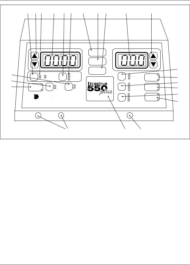
Dynatron 850plus Control Panel
Dynatron 850plus and Dynatron 550plus Physical Features
Before operating the Dynatron 850plus or Dynatron 550plus, acquaint yourself with the control panel by reviewing the illustrations and descriptions on this and the following pages. The numbered features in the diagrams correspond to the numbered descriptions. Before administering treatment to a patient, read the sections later in this manual that provide specific instructions for performing treatments, discussions of each modality, definitions of the available options, along with contraindications, warnings, and precautions for all modalities.
Note that some options use “toggle” keys for making selections. More specific instructions for using toggle keys are provided later in this section.
General Selections:
1.START: Pressing this key starts the treatment timer, and treatment proceeds as set up.
2.STOP: Pressing this key during a treatment IMMEDIATELY stops the output and sets the treatment time to zero for all modalities. Treatments may also be stopped by pressing the button on the patient REMOTE STOP cable. You can also stop a treatment for one treatment only by pressing and holding the Function
Installation & Features
7
|
|
|
|
|
Dynatron® 850plus & 550plus |
|
|
|
||||
6 |
4 |
7 |
5 |
8 |
9 |
1 |
2 |
3 |
10 |
|
11 |
|
|
|
|
|
TIME |
|
|
START |
|
POWER-INTENSITY |
|
||
|
|
|
|
|
|
|
|
|
|
|
|
|
|
|
|
|
|
|
|
STOP |
|
|
|
|
|
|
|
|
|
|
|
|
FUNCTION |
|
|
|
21 |
|
|
|
|
|
|
|
|
|
|
|
|
||
14 |
|
|
HV |
|
TIME |
|
|
|
|
NORMAL |
BIPHASIC |
|
|
CH |
1 |
|
FREQ |
|
|
|
CO-CONT |
19 |
|||
13 |
2 |
MICRO |
|
RATE |
|
|
|
|
RECIP |
RUSSIAN |
||
|
|
|
|
WIDTH |
|
|
|
|
||||
|
|
|
|
|
|
|
|
|
22 |
|||
|
|
|
|
|
|
|
|
|
|
|
||
|
|
|
|
|
|
|
|
|
|
10/10 |
+ |
|
12 |
IFC |
|
|
|
|
TARGET |
|
|
|
|
||
|
|
HIGH |
|
|
|
|
10/30 |
|
||||
|
|
|
|
|
|
HI VOLT |
20 |
|||||
|
|
|
|
SWEEP |
|
|
|
|||||
PREMOD |
|
|
LOW |
|
|
|
|
10/50 |
||||
|
|
|
|
|
|
|
|
- |
||||
|
|
|
|
|
|
|
|
|
|
CONT |
|
|
|
|
|
|
|
|
|
|
|
|
|
|
|
|
|
Dynatronics |
|
|
|
|
.5 RAMP |
+ |
23 |
|||
|
|
|
|
|
|
1.0 RAMP |
MICRO |
|||||
|
|
|
|
|
|
|
||||||
|
|
|
|
TARGET |
|
1.5 RAMP |
|
|||||
|
|
|
|
|
- |
|
||||||
|
|
|
|
|
|
|
|
|
2.0 RAMP |
24 |
||
|
|
|
|
|
|
|
|
|
|
|
||
|
|
|
|
|
|
|
|
|
|
|
|
|
|
CH 1 |
|
|
CH 2 |
|
|
|
|
|
HV |
|
|
|
|
|
|
|
25 |
|
|
|
15 |
26 |
|
|
Dynatron 550plus Control Panel
key while you press the Stop key, or by reducing that channel’s treatment time to zero.
3.PAUSE/FUNCTION: This key is used in combination with other key presses for accessing unique features including: select polarity (high volt and microcurrent), audio volume control (microcurrent), and to stop one treatment only. Specific instructions for using this key are provided later in this manual.
For Dynatron 850plus only: This key is also used to pause an ultrasound treatment. First press the channel toggle (CH) to select SOUND, then press PAUSE/FUNCTION; the ultrasound output is stopped, the treatment time is paused, and the light on the Pause key is on. When this key is pressed again, the ultrasound treatment resumes and the light on the Pause key is off. The PAUSE option is not available with the Dynatron 550plus since that model does not offer ultrasound. NOTE: During a Combo treatment, only the ultrasound output and the treatment timer are stopped when you press Pause; the stim output continues.
4.TIME ARROW KEYS: These UP/DOWN arrow keys are used to increase/decrease the treatment time or other parameter that is displayed in the Time display.
5.TIME DISPLAY: This display is used to show the treatment time for one treatment at a time; the display shows treatment time for the selected channel (the selected channel is indicated by the green LED—all other channels in use at the
Installation & Features
8

Dynatron® 850plus & 550plus
time will have yellow LEDs). The Time display can also display the pulse rate and width for Russian and biphasic treatments, as well as the frequencies for interferential, premodulated, and microcurrent treatments, and pulse rate for high volt. The treatment parameters for any treatment in progress may be displayed at any time by first using the channel toggle key to choose the desired channel then using the Time toggle key to select the desired parameter (Time, Freq, Rate, Width).
6.CHANNEL TOGGLE KEY(CH): When a treatment is in progress, you can press this key to choose an output channel and display the parameters for the treatment being delivered by that channel. When a channel light is GREEN, the displays show the settings for that channel. The available options depend on the modality selected. When two or more treatments are in progress simultaneously, the toggle key is used to select the channel you wish to view.
7.CHANNEL SELECTIONS: These lights indicate which output channels are currently in use. A solid GREEN light indicates current is being delivered to that channel; the time, intensity and other treatment parameters for that channel are also displayed. A solid YELLOW light indicates a channel is in use and delivering current, but the time, intensity, and treatment parameters are not displayed at this time (only one channel’s time and intensity may be displayed at a time). Flashing green or flashing yellow indicate the “off” segment of a biphasic, Russian or high volt treatment cycle. The channel’s intensity and other treatment parameters may only be modified when it has a green indicator light. Press the Channel Toggle key (CH) to select a channel to be viewed.
8.TIME TOGGLE KEY: Press this key to display various treatment parameters in the Time display including Time (treatment time), Freq (frequency), Rate (pulse rate), and Width (pulse width). Available options during a given treatment or treatment setup depend on the modality selected.
9.TIME GROUP SELECTIONS: These lights indicate the parameters that are displayed (one at a time) in the Time display. The default selection is the treatment time. Press the Time toggle key to select the desired option (available options depend on the modality selected). When a parameter is selected, its indicator light is green, its value is displayed in the Time display above, and the time arrow keys may be used to change the value. The device returns to the Time display after 10 seconds with no key presses.
10.POWER-INTENSITY DISPLAY: This display is used to display the treatment power (for ultrasound) or intensity (for all other modalities) for the currently selected channel (the selected channel is indicated by the green LED—all other channels in use at the time will have yellow LEDs). Press the channel toggle key to select the desired channel to be viewed.
11.POWER - INTENSITY ARROW KEYS: The arrow keys are used to increase/decrease the intensity or power of one treatment. Changes made to power and intensity affect only the currently selected channel (the selected channel is indicated by the green LED—all other channels in use at the time will have yellow LEDs). Press the channel toggle key to select the desired output channel. The arrow keys may then be used to change the intensity or power for that channel.
Installation & Features
9

Dynatron® 850plus & 550plus
IFC / Premod Selections:
12.IFC/PREMOD: Press this key once to begin setup of an interferential treatment (the IFC LED is lighted); press this key twice to begin setup of a premodulated treatment (the Premod LED is lighted). When you select IFC, both channels 1 and 2 are automatically selected and the green LED lights for those two channels will be on. Connect two leads to the output jacks for the channels that are selected. When you select PREMOD, a single channel (CH1 or 2) is automatically selected and that channel’s green LED will be on. Connect one lead to the output jack that corresponds to the channel indicated by the green LED.
13.HIGH/LOW TOGGLE (used with interferential, premodulated and high volt): Press this key one or more times to select the desired frequency range for interferential and premodulated treatments or the pulse rate range for high volt treatments. The green LED indicates the option selected. For example, press the High/Low toggle key once to select High, press again to select Low, press again to select High/Low Alternating, and press again to select High/Low Consecutive. For high volt treatments, you can select High or Low only, but not both. During a treatment, the current sweeps through the range(s) selected.
For interferential and premodulated, the HIGH frequency range is initially set at 80 to 150 Hz; and the LOW frequency range is 0 to 10 Hz. For high volt, the HIGH pulse rate range is initially set at 80 to 120 Hz; and the LOW pulse rate range is 1 to 10 Hz. These frequency ranges may be modified for every treatment, if desired and new default settings for the device may also be saved. See treatment setup instructions later in this manual for a complete description of the options that may be selected.
14.TARGET/SWEEP TOGGLE: This key is pressed to select either Target, Target Sweep, or static treatment for an interferential treatment. The Target pad is used to locate the exact treatment site (if the Target option is selected during an interferential treatment).
15.TARGET PAD: For use during interferential treatments when “Target” is selected. Touch the TARGET pad at different points on the pad to reach the precise treatment site. When you lift your finger from the Target pad, the selected point is locked until you change it again. This patented feature is used to locate the specific treatment site in an interferential treatment and to place the point of interference at that point.
Ultrasound Selections (DYNATRON 850plus ONLY—the ultrasound feature is not available on the Dynatron 550plus):
16.SOUND/COMBO: Press this key once to begin setup of an ultrasound treatment (the Sound LED on this key is lighted as well as the Sound LED in the channel indicator area); press this key twice to begin setup of a combination treatment (the Combo LED is lighted as well as the Sound LED and a single Channel LED in the channel indicator area). When either of these options is chosen, the soundhead should first be plugged into the ultrasound output jack on the side panel. For combination treatments, the special combo lead wire should be attached to the output jack selected (see full instructions for setting up a combination treatment later in this manual). In the COMBO mode, the electrotherapy treatment is delivered through the soundhead and through a single electrode which is placed on the patient. Only single-channel electrotherapy options are available in the COMBO mode.
Installation & Features
10

Dynatron® 850plus & 550plus
17.SOUND FREQUENCY TOGGLE: This key is pressed one or more times to select the desired ultrasound frequency; 1 MHz, 2 MHz, or 3 MHz.
18.DUTY CYCLE TOGGLE: This key is pressed one or more times to select the desired duty cycle for ultrasound treatment. Options are 10, 20, or 50 percent, or Continuous.
Russian / Biphasic / High Volt Selections:
19.BIPHASIC/RUSSIAN: Press this key once to begin setup of a biphasic treatment (the Biphasic LED is lighted); press this key twice to begin setup of a Russian treatment (the Russian LED is lighted). Biphasic and Russian treatments use a single channel (1 or 2) when the Normal mode is selected; and a channel pair (1 and 2) when the Reciprocal or Co-contraction mode is selected.
20.HIGH VOLT: Press this key to begin setup of a High Volt treatment (the Hi Volt LED is lighted). The HV output channel is automatically selected (the LED for the channel selected is GREEN). Connect the patient lead wire to the HV output jack.
HIGH VOLT POLARITY: To select or change the polarity of a high volt treatment, use the HI VOLT key together with the FUNCTION key. Press and continue holding the FUNCTION key while pressing the Hi Volt key one or more times to select positive only (the “+” LED is lighted), negative polarity only (the “-” LED is lighted), or both (both LEDs are lighted).
21.TREATMENT MODE TOGGLE (for biphasic and Russian treatments): Press this key one or more times to select Normal, Co-Contraction, or Reciprocal contraction. The output channel is automatically selected. When Normal is selected, one output jack only is selected (1 or 2). When Co-contraction or Reciprocal is selected, channels 1 and 2 are selected. Connect the patient lead wire(s) to the output jack(s) for the channel(s) selected.
22.CONTRACTION/REST CYCLE TOGGLE (for Russian, biphasic, and high volt treatments): Press this key one or more times to select the desired contraction/rest (on/off) cycle . Available cycles include 10/10, 10/30, 10/50, and Continuous. The first value indicates the on-time in seconds, and the second value indicates the off-time. For example; 10/30 indicates the current is on (muscle is contracting) for 10 seconds, and current is off (muscle is relaxed) for 30 seconds. With Continuous mode, current is applied continuously with no off cycle. The continuous duty cycle is not recommended for electrical muscle stimulation, but may be used for settings that are intended to effect other results than a muscle contraction.
23.RAMP TIME TOGGLE (for Russian, biphasic, and high volt treatments): This key is pressed to select the ramp time . The ramp time is applied before and after the “On” segment of the cycle (it provides both a ramp up and a ramp down). Available ramp times are .5, 1, 1.5, and 2 seconds.
NOTE: The High/Low option described previously under the Interferential/Premod options, is also used for High Volt treatments (see item 13 above).
Installation & Features
11
Dynatron® 850plus & 550plus
Microcurrent Selections:
24.MICRO: Press this key to begin setup of a microcurrent treatment. This key is also used to turn the conductance tone off and on after a microcurrent treatment is started. When MICRO is selected, Channel 1 is automatically selected for the default electrodes treatment and the LED for that channel is lighted. For a microcurrent treatment setup with electrodes, connect a patient lead wire to Channel 1 output jack. For a microcurrent probes treatment, press the channel toggle key (CH) to select the MICRO channel selection (Channel 1 LED will become yellow and MICRO will become green to indicate the probes option is selected). Connect the microcurrent probe to the microcurrent output jack on the left side panel of the device.
NOTE: Channel 1 is committed to the microcurrent output during a probes treatment as well as during a treatment with electrodes, and is not available for use by any other modality while any microcurrent treatment is in progress.
MICROCURRENT POLARITY: To select or change the polarity of a microcurrent treatment, use the MICRO key together with the FUNCTION key. Press and continue holding the FUNCTION key while pressing the MICRO key one or more times to select positive only (the “+” LED is lighted), negative polarity only (the “-” LED is lighted), or dual polarity (both LEDs are lighted).
25.OUTPUT JACK CHANNELS 1 and 2: These are the output jacks for delivering interferential, premodulated, Russian, biphasic, and microcurrent treatments. Consult treatment instructions later in this manual for appropriate channels and treatment setup for each modality.
26.HIGH VOLT OUTPUT JACK HV. This is the output jack for delivering high volt treatments. Consult treatment instructions later in this manual for high volt treatment setup.
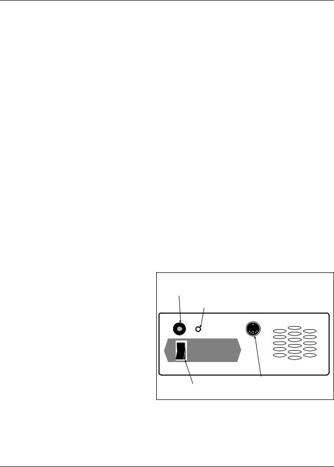
Dynatron 850plus and
550plus Back Panel: 28. Electrical Stim to Ultrasound Input Jack (only on D850plus)
27. POWER ON/OFF |
29. Jack for Optional Battery Pack |
|
|
SWITCH: Located on the |
|
back of the unit this switch |
Batt. Input |
|
is labeled “1” and “0”. Set |
||
|
||
the switch to “1” for ON; |
1 |
|
set the switch to “0” for |
||
|
||
OFF. |
0 |
|
|
28. STIM INPUT JACK FOR COMBINATION TREATMENTS: The special lead wire for combination treatments is plugged into this jack for a combination
treatment setup providing stim output through the ultrasound head. The special lead wire is also plugged into the jack on the front of the device which has been selected for the specific combo treatment. See combination treatment instructions later in this manual for detailed information regarding combination treatment setup.
Installation & Features
12
Dynatron® 850plus & 550plus
9.BATTERY: This jack may be used to supply power to the device using an optional battery pack. More information about the optional battery operation is provided later in this manual.
30.REMOTE STOP: A cord with a remote stop button is inserted in this jack. The remote stop is controlled by the patient during unattended therapy to allow the patient to stop the treatment at any time. When the button on the remote stop cable is pressed, output for all stim modalities is stopped and the tone sounds briefly. During Combo treatments, both sound and stim outputs are stopped.
Right side of device (D850plus only) Left side of device
Ultrasound |
Micro Probe |
31. Ultrasound Ouput Jack |
32. Ouput Jack for Microcurrent Probe |
Side Panels
Dynatron 850plus and 550plus Side Panels:
31.ULTRASOUND OUTPUT JACK (DYNATRON 850plus ONLY—not available on the Dynatron 550plus): The applicator soundhead plugs into this jack for ultrasound therapy.
32.MICROCURRENT OUTPUT JACK: The microcurrent probe plugs into this jack for microcurrent probe therapy.
Instructions for Using Toggle Keys
Toggle keys are used to make selections from two or more options in a given area. Toggle keys are pressed one or more times to make a desired selection. A GREEN light (LED) next to the toggle key shows the option that has been selected. Pressing the toggle key one or more times allows you to scan through the available options.
Each toggle key has unique capabilities. Most toggle keys allow only one selection. For example, the Ramp toggle key requires you to select just one of the four ramp times available. However, some toggle keys allow you to select two options. For example, in interferential you can press the High/Low toggle key once to select High, press again to select Low, and press again to select both High and Low.
The following is a list of all the toggle keys available with each modality:
Installation & Features
13
Dynatron® 850plus & 550plus
IFC and Premod
•Target/Sweep (IFC only)
•High/Low Frequency Ranges
Russian and Biphasic Stim
•Treatment mode
•Contraction/Rest cycle
•Ramp Time
High Volt Stim
•Contraction/Rest cycle
•Ramp Time
•Polarity
•High/Low Pulse Rate Ranges
Microcurrent
•Microcurrent Polarity
•Channel toggle to select Micro or Channel 1 (during setup only)
All Modalities
•Time/Frequency/Rate/Width
•Channel Toggle (to view individual channels one at a time while treatments are in progress
Ultrasound (Dynatron 850plus only)
•Ultrasound Frequency
•Ultrasound Duty Cycle
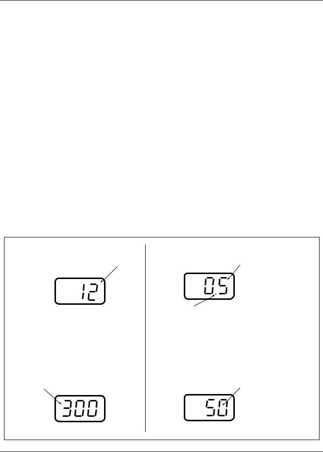
Stim Intensity Display |
Ultrasound Power Display |
||||
The intensity display is intended as an |
Ultrasound power is displayed, with the value |
||||
incremental value only for the convenience |
shown either in WATTS or W/cm2. |
||||
of the practitioner. |
POWER-INTENSITY |
||||
|
|
|
|||
POWER-INTENSITY |
|
|
|
||
|
|
|
|
|
|
|
|
|
|
|
|
|
|
|
|
|
|
Increasing the intensity does increase |
A blinking decimal indicates the power is displayed |
||||
current delivery. However, intensity and |
as WATTS. A steady (non-blinking) decimal |
||||
current are not a 1:1 comparison. Actual |
indicates WATTS/cm2. Pressing and holding the |
||||
current delivered to the patient depends |
PAUSE key changes the display from WATTS to |
||||
upon the intensity setting and the current |
W/cm2 or reverse. |
||||
density (affected by the size and |
|
|
|
||
condition of the electrodes). |
|
|
|
||
|
|
|
|
||
Microcurrent Intensity Display |
High Volt Intensity Display |
||||
Microcurrent intensity is displayed in |
High volt intensity is displayed in volts |
||||
microamperes |
|
|
|
||
POWER-INTENSITY |
POWER-INTENSITY |
||||
|
|
|
|
|
|
|
|
|
|
|
|
|
|
|
|
|
|
Examples of Power-Intensity displays for the Dynatron 850plus and 550plus.
Installation & Features
14
Dynatron® 850plus & 550plus
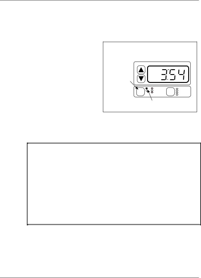
Time and Power Displays
The “Time” display and the “Power-Intensity” display can show the settings for only one channel at a time. The Time and Power-Intensity settings displayed are for the channel with the GREEN light only. Any other channel in use at that time will have a YELLOW light to show it is active but its parameters are not currently displayed.
To view the settings for another |
When a channel is selected its parameters are displayed in |
|||||
channel or output, press the channel |
||||||
the Time and Power-Intensity displays, and treatment |
||||||
toggle key one or more times until |
parameters for that treatment may be modified. |
|
|
|||
the light for the desired channel |
|
|
|
|
|
|
becomes GREEN. The GREEN |
Press the |
|
TIME |
|
|
|
light appears next to a different |
|
|
|
|
||
channel toggle |
|
|
|
|
||
channel or output each time you |
|
|
|
|
||
key to select any |
|
|
|
|
||
press the toggle key, and the Time |
channel that is |
|
|
|
|
|
and Power-Intensity displays change |
currently in use. |
|
|
|
|
|
to show the parameters currently in |
|
2 |
MICRO |
FREQ |
||
|
|
1 |
HV 1 |
TIME |
||
effect for that channel. |
CH |
|
SOUND |
RATE |
||
|
|
|
WIDTH |
|||
The green and yellow channel lights each will also appear solid (nonflashing) or flashing. A solid light means current is being delivered to
the channel at this time (for example, during the ON cycle of the Russian stimulation treatment). A flashing light means current is not being delivered to the channel at this time (for example, during the OFF cycle of the Russian stimulation treatment).
CHANNEL / OUTPUT INDICATOR LIGHTS
GREEN Solid • You CAN see this channel’s parameters displayed on Time and Power-Intensity displays.
• The channel IS delivering current.
GREEN Flashing • You CAN see this channel’s parameters displayed on Time and Power-Intensity displays.
• The channel IS NOT delivering current.
YELLOW Solid • You CANNOT see this channel’s parameters displayed on Time and Power-Intensity displays.
• The channel IS delivering current.
YELLOW Flashing • You CANNOT see this channel’s parameters displayed on Time and Power-Intensity displays.
• The channel IS NOT delivering current.
Ultrasound Heads (Dynatron 850plus only)
The Dynatron 850plus features the new Dynatronics SmartHead™ ultrasound applicator soundhead that has all calibration information self-contained. SmartHeads may be used interchangeably with any 50 Series Plus model or the Dynatron 125 model with no need for entering calibration numbers into the device.
Installation & Features
15

Dynatron® 850plus & 550plus
Soundheads for the Dynatron 850plus come in 1 cm2, 2 cm2, 5 cm2, and 10 cm2 sizes. The 2 cm2, 5 cm2, and 10 cm2 soundhead operate at 1, 2, and 3 MHz; while the 1 cm2 soundhead operates at 2 and 3 MHz. The soundheads are waterproof allowing ultrasound (not combination) therapy to be administered in water, if desired.
Do not drop the soundhead nor allow it to strike a hard surface. Do not place soundheads into ice water. Do not allow soundheads to repeatedly reach maximum head temperature. All of these conditions can cause damage to the crystal. Any such damage is not covered by the warranty.
For new or replacement soundheads, contact Dynatronics or your authorized Dynatronics representative.
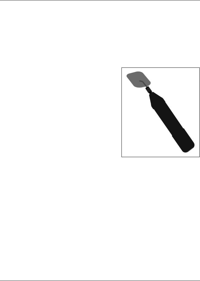
Microcurrent Probes (optional accessory)
The Dynatron 850plus and Dynatron 550plus devices offer optional probes for delivering hands-on microcurrent treatment. The microcurrent probes can only be used for microcurrent therapy. It is not possible to select the probe output nor to use the microcurrent probe to deliver a probe treatment for interferential, premodulated, Russian, biphasic, or high volt modes.
The setup includes an active probe along with either a ground probe or a ground electrode. Use the end of a cotton swab (such as a Q-Tip®) inserted into the ends of both the active probe and the ground probes. Cut the end of the swab to a short length; the cotton must touch the probe’s metal ring. Use water or a conductive electrolyte spray to wet the cotton swab before treating.
Active Probe: To deliver the current to the patient through the active probe, press and release the button on the probe. Press and release the button again to stop the current. The active probe should touch the patient’s skin at the treatment site, and the ground probe should touch the patient’s skin elsewhere. This completes the circuit and delivers current to the patient. You do not need to hold the button down. Once you have pressed and released the button, the current is delivered until you press and release the button again to stop the current.
While you are delivering current, the treatment timer counts up in seconds from zero. When the current is stopped, the timer returns to zero. Press the button again to commence the next time sequence. Continue in this way until treatment is completed.
Ground Probe: The ground probe is attached directly to the banana pin connector on the probe
cable. This probe is used to complete the circuit to allow flow of current through patient tissue. The ground probe should touch the patient’s skin at any location away from the treatment point. As an alternative, you may also use a ground electrode as explained below,
Installation & Features
16
Dynatron® 850plus & 550plus
in place of the ground probe. This is particularly convenient when treating in several different places around one point.
Ground Electrode: You can use an electrode in place of the ground probe. Just unplug the ground probe from its cable, attach a banana-to-pin adapter to the cable, then attach an electrode to the pin. Place the electrode on the patient at a site where it will not interfere with placement of the active probe during treatment. The banana-to-pin adapter is an optional accessory available from Dynatronics.
High Volt Probe (optional accessory)
An optional probe may be purchased which allows you to deliver an attended high volt treatment. The high volt probe is connected to the dedicated high volt jack (HV) on the front of the machine. The probe is used in conjunction with a large dispersive electrode. The high volt probe is used only for delivering high volt therapy.
Complete setup and use instructions are provided in this manual under the treatment setup instructions for high volt.
High Volt Probe (optional accessory)
Installation & Features
17

Dynatron® 850plus & 550plus
Quick Reference of Special Key Presses
The following is a brief list of special key presses available with this device. These options are explained in detail where they apply in the treatment instructions later in this manual. NOTE: Where two keys are required (ie, FUNCTION-STOP) you must press both keys simultaneously to achieve the result.
KEY PRESS |
RESULT |
DESCRIPTION |
|
|
|
|
|
FUNCTION-STOP |
STOP TREATMENT |
Stop one treatment |
|
|
|||
|
|
|
|
FUNCTION-HI VOLT |
CHANGE HIGH VOLT POLARITY |
Change high volt polarity. Repeat to change again. |
|
|
|||
|
|
|
|
|
|
Press during IFC, premod or mcrocurrent treatment to view |
|
FUNCTION-TIME |
CONDUCTANCE BAR GRAPH |
conductance bar graph. Press TIME to return to normal display. |
|
|
|
|
|
FUNCTION-SOUND |
HEAD WARMING ON/OFF |
Set head warming feature to on (HD 1) or off (HD 0) |
|
|
|
||
|
|
|
|
SOUND-TARGET |
ULTRASOUND COUPLING BAR |
During an ultrasound treatment only, press to view the ultrasound |
|
coupling bar graph. Press TIME to return to normal display. |
|||
|
GRAPH |
||
|
|
||
|
|
|
|
|
SOUNDHEAD TEMPERATURE BAR |
During an ultrasound treatment, press to view the ultrasound head |
|
SOUND-HI/LO keys |
temperature bar graph. Press TIME to return to normal display. |
||
GRAPH |
|||
|
|
||
|
|
|
|
|
|
During ultrasound treatment hold for 2 seconds to change |
|
FUNCTION |
DISPLAY WATTS or W/cm2 |
ultrasound power display from w/cm2 to Watts or reverse. |
|
|
|
|
|
FUNCTION- |
|
Enter the Lead Test Function. Then press START to begin lead |
|
|
test, and press STOP to exit the lead test function. NEVER DO |
||
TARGET/SWEEP key |
TEST LEADS |
||
THIS WHILE ELECTRODES ARE ATTACHED TO PATIENT. |
|||
|
|
||
|
|
|
|
FUNCTION-MICRO |
CHANGE MICROCURRENT |
Change microcurrent polarity. Repeat to change again. |
|
|
POLARITY |
|
|
MICRO |
AUDIO TONE ON/OFF |
During a microcurrent treatment, turn audio tone on and off. |
|
|
|||
|
|
|
|
FUNCTION-INTENSITY |
|
Change loudness of tone (during microcurrent treatment only) |
|
UP & DOWN ARROW |
CHANGE VOLUME |
||
|
|||
KEYS |
|
|
|
START |
SAVE NEW DEFAULT SETTINGS |
Hold for 2 seconds to save defaults for current treatment. |
|
|
|||
|
|
|
The following key presses are applied only when powering up the device:
AT POWER ON, HOLD DOWN THE FOLLOWING KEYS WHILE THE DEVICE STARTS UP:
|
TARGET/SWEEP |
LEAD TEST MODE |
Press and hold on power up to enter Lead Test feature. |
|
|
||
|
|
|
|
|
|
|
Press and hold on power up and wait for beep to restore factory |
|
START |
RESTORE FACTORY SETTINGS |
default settings. |
|
|
|
|
|
|
|
Press and hold on power up to enter soundhead calibration mode |
|
FUNCTION |
ENTER CALIBRATION MODE |
(for technicians only) |
|
|
|
|
|
ULTRASOUND DUTY |
ENTER SOUNDHEAD |
Press and hold on power up to enter soundhead parameter entry |
|
mode (for technicians only) |
||
|
CYCLE KEY |
PARAMETERS |
|
|
|
||
|
|
|
|
|
|
|
Press and hold these keys at the same timeto disable the |
|
FUNCTION-TIME MODE |
|
conductance bar graph for treatment setup (the graph will still be |
|
DISABLE CONDUCTANCE BAR |
available for viewing after a treatment has started). After the |
|
|
KEY |
||
|
GRAPH |
device starts up, select 1 (in the intensity screen) to turn the option |
|
|
(Rev 1.02 and later) |
||
|
|
on and 0 to turn the option off. |
|
|
|
|
|
|
|
|
|
|
|
|
Press and hold these keys to disable the ultrasound coupling |
|
FUNCTION-INTENSITY |
DISABLE ULTRASOUND COUPLING |
detection feature. The Time display will show the current setting |
|
DOWN ARROW |
briefly: CP1=feature on, CP0=feature off. Repeat this step to |
|
|
DETECTION |
||
|
(Rev 1.02 and later) |
revert to the prior setting. |
|
|
|
||
|
|
|
|
|
|
|
|
Installation & Features
18

Dynatron® 850plus & 550plus
Section II
Operation and Treatment
Instructions
Operation & Treatment Instructions
19

Dynatron® 850plus & 550plus
General Operating Instructions
Power On/Off
Press the power switch located on the rear panel of the unit. The self-diagnostic and calibration function automatically occurs each time the unit is turned on. It is recommended that the unit remain on throughout the day if it is used on a regular basis.
CAUTION: Never turn power on or off while the unit is connected to the patient. Set intensity to minimum power before pressing START.
Basic Treatment Setup
Treatment setup is simple and fast with the Dynatron 850plus and 550plus. Each modality has default settings that are automatically selected when you press a modality key. The basic steps for setting up any treatment are:
1.Press a modality key once or twice to choose the desired modality (IFC, Premod, Russian, Biphasic, High Volt, Micro, Sound, or Combo). The lighted LED on the key indicates the modality chosen. The first available output channel(s) and default settings for that modality are automatically selected. For ultrasound and combination treatments, the soundhead must be connected to the device before selecting Sound or Combo.
2.Plug lead wires or probe cable into the appropriate jack(s) on the device for the modality to be delivered. Observe which channels the device selected for this treatment—channels are selected automatically by the device. Attach the electrodes to the leads, and affix the electrodes to the patient. For unattended stim treatments, attach the Remote Stop cable, and give the cable to the patient
3.Change any options desired using the toggle keys available for that modality.
4.Increase power or intensity. Current delivery to the patient starts when you increase intensity. Only do this when you are ready to proceed with the treatment.
5.• For Target treatments only, locate the treatment site using the Target pad.
•For Russian / biphasic two-channel treatments, press Start or the channel toggle key after setting the intensity for the first channel, then set the intensity for the second channel.
•For Combo treatments, set the parameters for the stim modality (or ultrasound), press Start, then set parameters for ultrasound (or stim), then press Start again. You can select the desired stim modality in this step by pressing the desired modality key after pressing Combo.
6.Press Start. The treatment timer begins.
Operation & Treatment Instructions
20
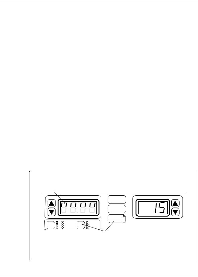
Dynatron® 850plus & 550plus
7.Administer treatment until the treatment time expires, or press STOP to stop all treatments in progress at any time.
Each of the therapies you can deliver with the Dynatron 850plus and 550plus offers its own default settings. To make your treatment setup even more convenient, the Dynatron 850plus and 550plus allow you to change the defaults for each modality to your own most common treatment selections. See “Setting Defaults” later in this manual.
The following pages provide more detailed setup instructions for each individual modality.
Before administering a treatment to a patient, be sure to read all treatment instructions as well as contraindications, warnings, and precautions for that modality provided later in this manual. Also, consult published literature for recommended application of these modalities.
Conductance Bar Graph
This feature for models having software greater than Rev. 1.01 only (see Page 2).
During setup of an interferential or premodulated treatment, a conductance graph is automatically displayed in the Time display while you set the treatment intensity. The graph allows you to see whether conductance is good for that treatment setup and if current is being delivered efficiently through the electrodes. The display reverts to the Time display when you press any other key after setting the intensity. You may again view this conductance graph at any time during an interferential, premodulated, or microcurrent treatment by pressing FUNCTION-TIME. The conductance bar graph is not available for combination treatments.
The bar graph uses the eight segments in the top half of the display, with eight lighted segments indicating best conductance, and one lighted segment indicating poorest conductance. In the illustration below, eight of the eight segments are lighted indicating good conductance.
Conductance Bar Graph
Eight lighted segments indicate conductance is good. If only two or three segments are lighted, conductance is poor.
|
|
TIME |
POWER-INTENSITY |
|
|
|
START |
|
|
|
STOP |
|
|
|
PAUSE |
|
1 |
HV 1 |
FUNCTION |
|
TIME |
||
CH |
2 |
HV 2 |
FREQ |
3 |
MICRO |
RATE |
|
|
4 |
SOUND |
WIDTH |
During an IFC, Premodulated, or Microcurrent treatment, press the FUNCTION and the TIME keys simultaneously to see the conductance graph. Press TIME to return to the treatment time display.
The graph is automatically displayed when the intensity is increased during treatment setup for IFC and Premod.
Conductance Bar Graph.
Operation & Treatment Instructions
21

Dynatron® 850plus & 550plus
If the graph indicates poor conductance, check to be sure leads and electrodes are in good condition, that leads are fully plugged in and the entire surface of the electrode is making contact with patient’s skin. Extremely dry skin can also be a cause of poor conductance. If leads or electrodes are found to be worn, they should be replaced. Leads may be tested using the Lead Test function described in the operator’s manual for this device. Guidelines for replacing leads and electrodes are also provided in the operator’s manual.
When you no longer wish to view the conductance graph, press the TIME key to redisplay the treatment time. NOTE: The treatment time counter does not stop, but continues counting down when the graph is displayed.
Disable the Conductance Bar Graph. If you do not wish to see the conductance bar graph automatically during the treatment setup, you can disable this function. Press and hold the FUNCTION and TIME mode keys while powering the device on (NEVER TURN THE DEVICE ON OR OFF WHILE LEADS ARE CONNECTED TO A PATIENT). When the device completes starting up, the word “bar” appears in the TIME display, and “1” appears in the Power/Intensity display. Use the intensity up/down arrow keys to change from “1” to “0” (select 1 to turn this option on, select 0 to turn the option off). Press START after making your selection. Once you have disabled the automatic portion of this option, the device will default to the disabled mode each time the device is powered on. However, you may still view the conductance graph at any time after the treatment has started as described above. If you wish to reset the default to re-enable the bar graph to appear automatically during treatment setup, again press and hold the FUNCTION and TIME mode keys while powering the device on and select the desired setting.
“LEAD” Warning - No Patient Current
This feature for models having software greater than Rev. 1.01 only (see Page 2).
This added safety feature warns you if the device detects an “open” or incomplete circuit during setup of an interferential treatment. An open can be due to a lead that is not plugged in, an electrode that has fallen off or otherwise is not making contact with the patient, or another reason that would cause an incomplete circuit. When this occurs, current is not being delivered to the patient, and the condition must be corrected before continuing with treatment setup.
"LEAD" ERROR - No Patient Current |
|
TIME |
POWER-INTENSITY |
|
START |
|
STOP |
|
PAUSE |
|
FUNCTION |
No Patient Current. During an interferential treatment setup, if an open is detected, the “Lead” warning is displayed along with the channel number that triggered the error.
When the device detects this condition during the treatment setup, it will beep and display “LEAD” in the Time display, and will indicate in the Intensity display the number of the channel that has triggered the error (for example, CH1), and you will be unable to increase the intensity setting. If this error occurs, reduce the intensity for the channel indicated, correct the condition, then return the intensity to the desired treatment level. In adjusting
Operation & Treatment Instructions
22
 Loading...