

Page 1
DYNAPAC
CS 141
OPERATION
O141EN4
Box 504, SE-371 23 Karlskrona, Sweden
Phone: +46 455 30 60 00, Fax: +46 455 30 60 30
www.dynapac.com
Page 2

ILF015WO1
19
Page 3
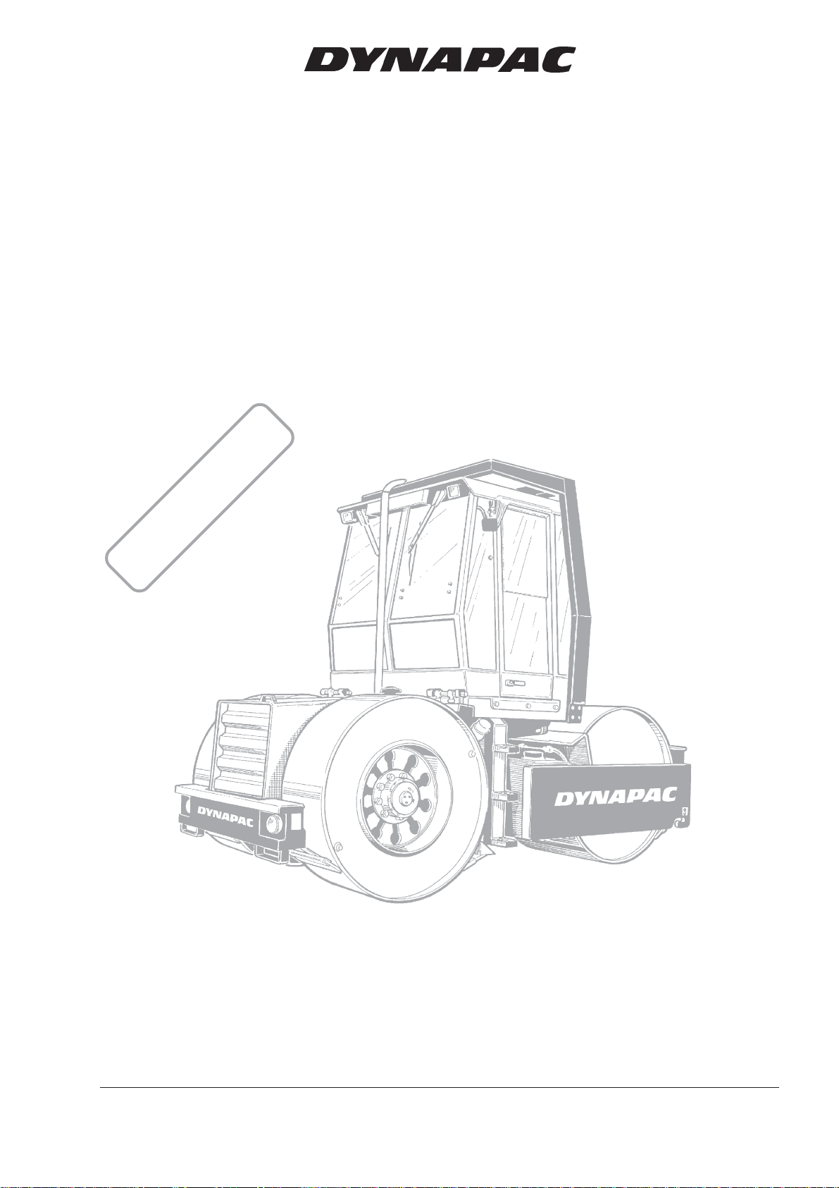
Static Three-drum Roller
CS 141
Operation
O141EN4, April 2002
Diesel engine:
Cummins 4BT-3.9
These instructions apply from:
CS 141 PIN (S/N) *21720192*
CS 141 PIN (S/N) *21720211* (New instrument panel)
KEEP THIS MANUAL FOR
FUTURE REFERENCE
Dynapac CS 141 is a static 10–13 tonne articulated 3-drum roller. The drums have the same dia-
meter and the line load is equal over the entire width. Propulsion and brakes on all three drums.
Good working environment for the operator. The ergonomically designed cab, with its amply sized
windows facilitates a complete all-round view. The cab is an optional feature,
but is described in this manual.
Reservation for changes.
Printed in Sweden.
Page 4
CONTENTS
Page
Safety instructions (Also read the safety manual) ........... 3
Safety when driving ...................................................... 4, 5
Safety decals, location and description ........................ 6, 7
Machine and engine plates ............................................... 8
Instruments and controls .................................................. 9
Instruments and controls, functional description ...... 10 ,11
Instruments and controls, cab (Optional) ....................... 12
Instruments and controls in cab, functional description . 13
Before starting .......................................................... 14, 15
Starting ........................................................................... 16
Operation ....................................................................... 17
Driving ............................................................................ 18
Braking ........................................................................... 19
Parking ........................................................................... 20
Lifting .............................................................................. 21
Towing ............................................................................ 22
Transport ........................................................................ 22
Operating instructions - Summary ................................. 23
WARNING SYMBOLS
WARNING
Safety instructions—Personal safety.
CAUTION
Special caution—Machine or component damage.
SAFETY MANUAL
WARNING
Each operator of the roller must study the
safety manual that accompanies each machine. Always follow the safety rules and do not
remove the manual from the roller.
GENERAL
This manual contains instructions for operation and use of
the roller. For care and maintenance information, see the
MAINTENANCE, CS 141 manual.
WARNING
Remember that when you start and drive a
cold machine, the hydraulic fluid is cold and
the braking distance will be longer than normal until the machine reaches normal working
temperature.
CALIFORNIA
Proposition 65 Warning
Diesel engine exhaust and some of its
constituents are known to the State of
California to cause cancer, birth defects,
and other reproductive harm.
2
CS 141 O141EN4
Page 5

SAFETY INSTRUCTIONS (Also read the safety manual)
WARNING
1. The operator must be familiar with the contents of the OPERATION
MANUAL before starting the roller.
2. Make sure that all instructions in the MAINTENANCE MANUAL are
followed.
3. Only trained and/or experienced operators are allowed to drive the
roller. Passengers are not allowed on the roller. Remain seated during
all operation.
4. Never use the roller if it is in need of adjustment or repairs.
5. Board and leave the roller only when it is stationary. Use the grips and
railings that are provided. A ”three-point grip” is recommended
whenever you board or leave the machine—both feet and one hand, or
one foot and both hands in contact with the machine.
6. Always use the Roll Over Protective Structure (ROPS) when the
machine is used on risky ground.
7. Drive slowly in sharp bends.
8. Avoid driving at an angle on slopes; drive straight up or down.
9. When driving close to unsafe edges or holes, make sure that at least two
thirds of the drum width is firmly on material that has already been
compacted.
10. Make sure that there are no obstacles in the direction of travel, on the
ground or overhead.
11. Drive extra carefully on uneven ground.
12. Use the safety equipment provided. The seat belt must be worn on
machines fitted with ROPS.
13. Keep the roller clean. Clean dirt and grease from the operator’s platform
without delay. Keep all signs and decals clean and clearly legible.
14. Safety measures before refueling:
– Stop the engine.
– Don’t smoke.
– No naked flame in the vicinity.
– Ground the nozzle of the filling device against the tank to prevent
sparks.
15. Before repairs or service:
– Place chocks against the drums/wheels and against the strike-off
blade.
– Lock the articulation if necessary.
16. Hearing protectors are recommended if the noise level is higher than 85
db(A). The noise level will vary depending on the surface being worked
on by the machine.
17. Make no changes or modifications on the roller that could affect safety.
Changes may only be made following written consent by Dynapac.
18. Do not use the roller until the hydraulic fluid has reached its normal
working temperature. Braking distance can be longer than usual if the
fluid is cold. See starting instructions in the OPERATION MANUAL.
CS 141 O141EN4
3
Page 6
SAFETY WHEN DRIVING
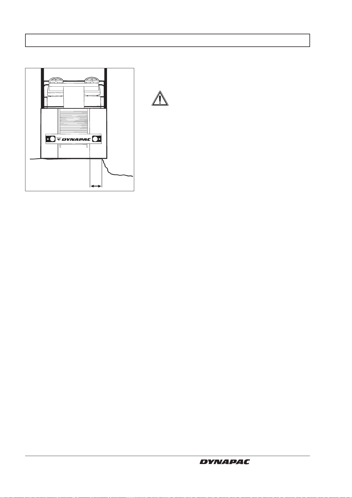
Driving near an edge
At least
2/3
Fig. 1 Position of drum when driving near
an edge
When driving near an edge, at least two thirds of the
drum width must be on solid ground.
WARNING
Remember that the machine’s center of
gravity is displaced outwards when steering to one side. For example, it moves to
the right when steering to the left.
4
CS 141 O141EN4
Page 7
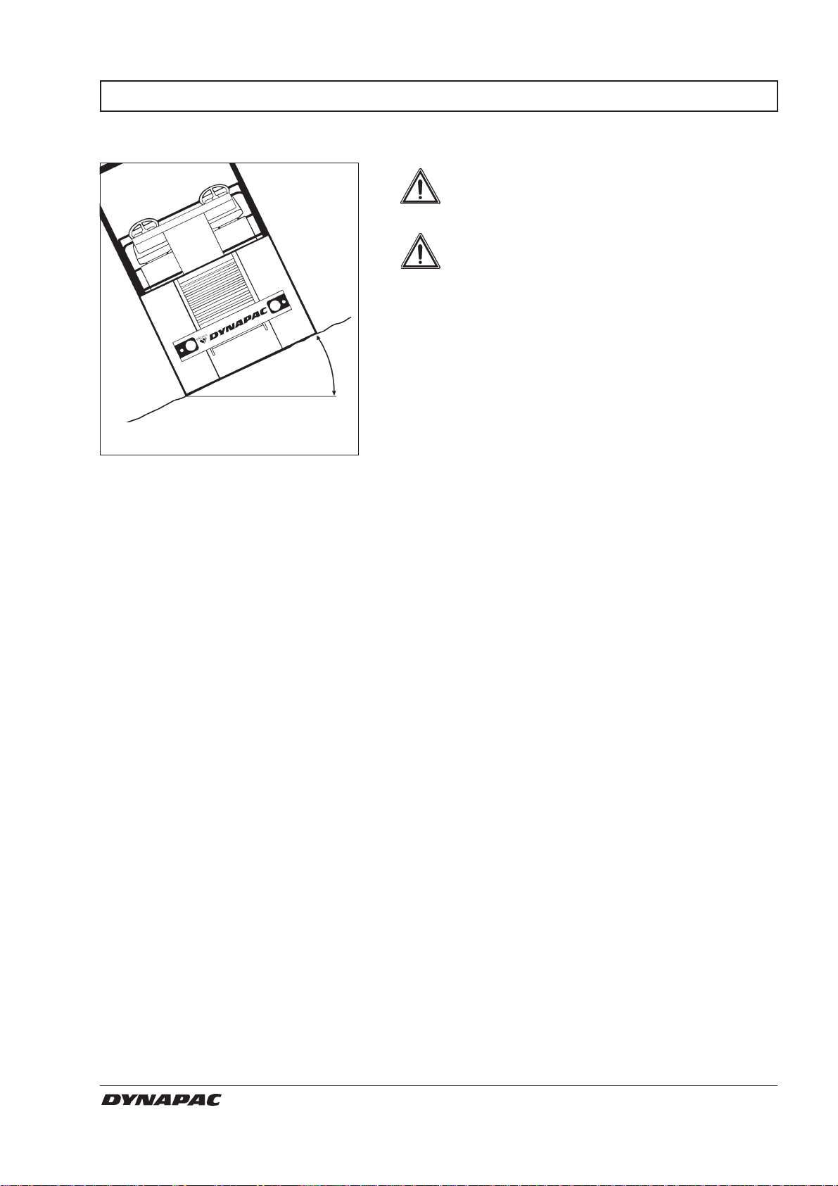
SAFETY WHEN DRIVING
Slopes
Max. 30°
or 58%
Fig. 2 Tipping angle on side slopes
WARNING
The ROPS (Roll Over Protective Structure)
is always recommended when driving on
slopes or insecure ground.
WARNING
Where possible, avoid all driving
across
a
slope. Instead, drive up and down on sloping ground.
The tilting angle is measured on a hard, level surface
with the machine stationary, steering angle zero, vibration switched OFF and all tanks full. Remember that
loose ground, steering of the machine, vibration switched ON, driving speed and raising the center of
gravity (for example, with accessories) may cause the
machine to topple even on a smaller slope than that
stated here.
CS 141 O141EN4
5
Page 8
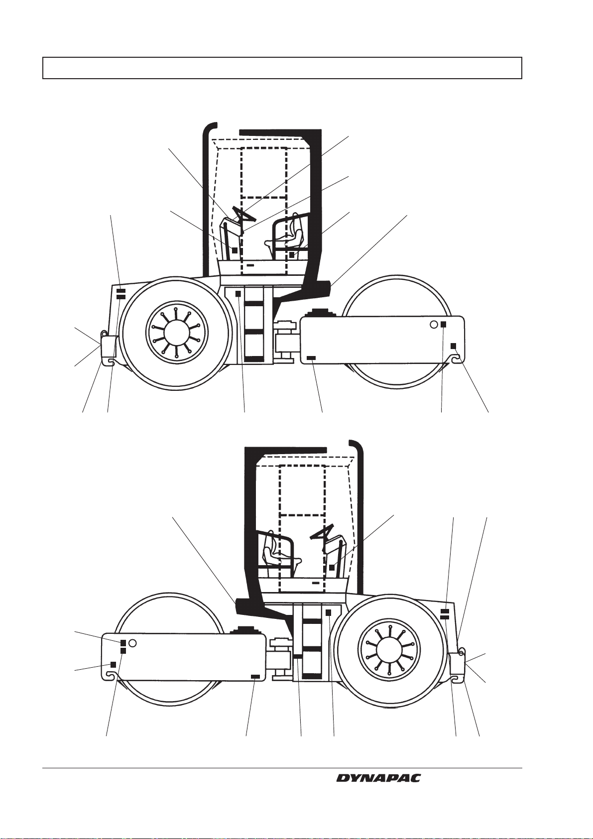
SAFETY DECALS, LOCATION AND DESCRIPTION
8
5
5
11
2
4
3
15
5
13
1 109
7
15
7
11
15
4
16
12
6
213
CS 141 O141EN4
14
14
10
3
15
Page 9
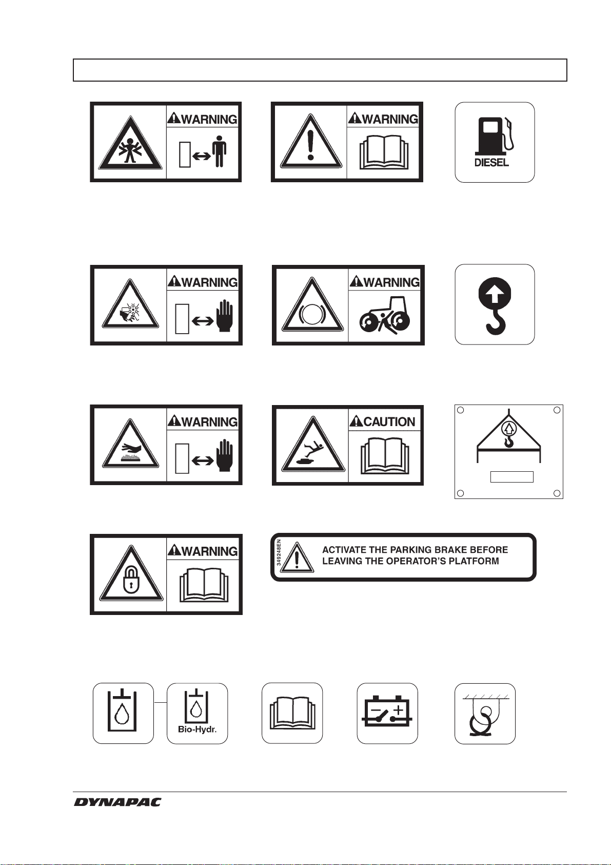
SAFETY DECALS, LOCATION AND DESCRIPTION
1.
Crush zone, articulation/
drum. Maintain a safe distance from the crush zone.
2.
Warning rotating engine
components. Keep your
hands at a safe distance from
the danger zone.
3.
903422
903423
5.
The operator is urgently
requested to read the safety
manual, and the operation
and maintenance instructions, before using the
machine.
6.
Study the towing chapter
before disengaging the
brakes. Danger of being
crushed.
7.
903459
904895
9.
991658
Diesel fuel
10.
588176
Lifting point
11.
Warning very hot surfaces
in the engine compartment.
Do not touch.
4.
The articulation joint must be
locked while lifting. Read the
instruction manual.
Alt. 1 Alt. 2
12.
272372
Hydraulic
fluid
Biological
hydraulic
fluid
904601
903424
908229
Warning danger of slipping
or falling. Read the instruction manual.
8.
13.
903425
14.
Handbook
compartment
disconnecter
904406
904835
Battery
Mass Kg
904870
Hoisting plate
15.
382751
Securing
point
CS 141 O141EN4
7
Page 10
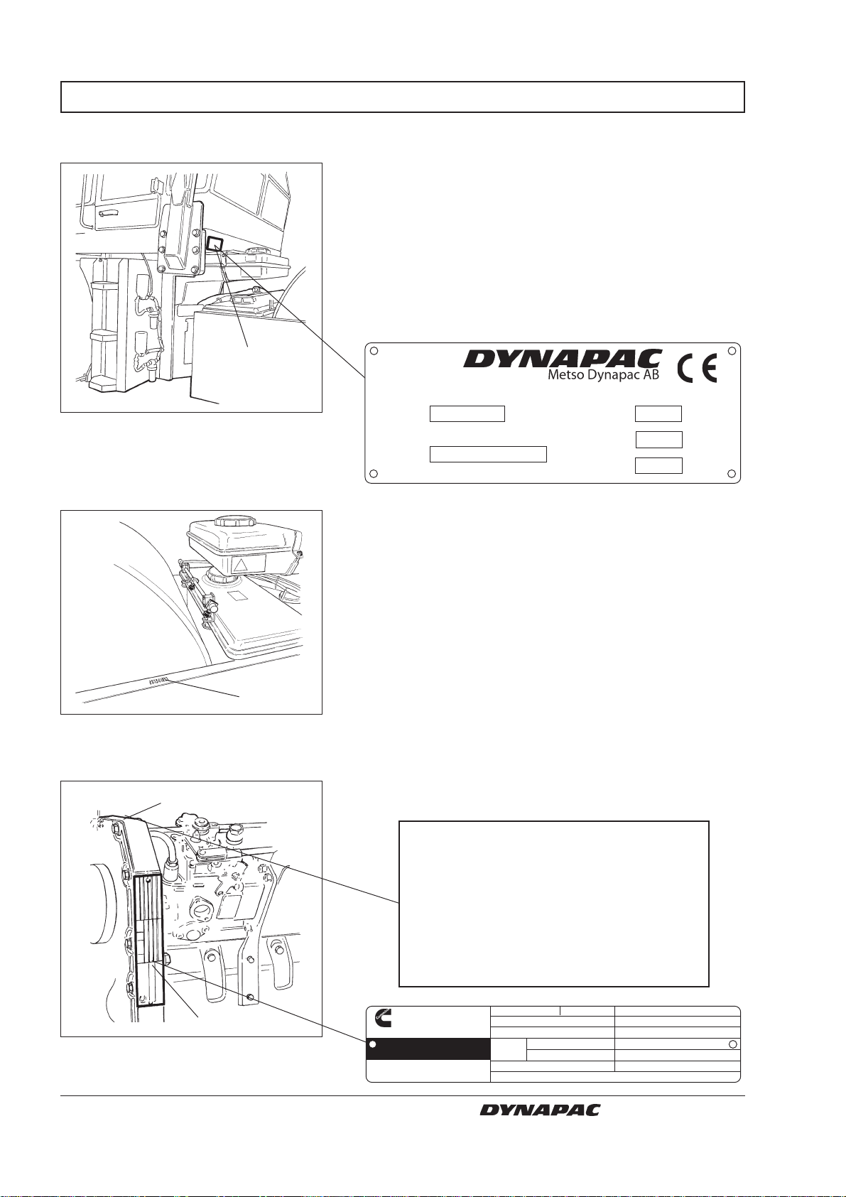
MACHINE AND ENGINE PLATES
Machine plate
1
Fig. 3 Operator’s platform
1. Machine plate
Serial number on frame
The machine type plate (1) is affixed on the rear left
edge of the operator’s platform. The plate shows the
manufacturer’s name and address, type of machine,
PIN—”Product Identification Number” (serial number)—
weight in working order, engine power and year of
manufacture. (Only the manufacturer’s name and
address, PIN and type of machine will be noted if the
machine is delivered outside the EU.)
Please specify the PIN (serial number) of the roller
when ordering spares.
Karlskrona Sweden
Type
Product
Operating mass
Rated power
kg
kW
Ident.
Number
Year of Mfg
The PIN (1) of the frame is punched on the right side of
the front frame.
Fig. 4 Front frame
1. Serial number
Engine plate
Fig. 5 Engine
1. Engine plate
2. EPA sign (USA)
8
1
The machine type plate (1) includes the serial number.
Please specify the engine serial number and PIN when
ordering spares. See also the engine manual. On
Cummins’ diesel engines, the engine type plate is fitted
2
1
on the right edge of the toothed belt cover.
IMPORTANT ENGINE INFORMATION
This engine conforms to 1999 U.S. EPA
and California regulations for
heavy duty non-road compression
ignition diesel cycle engines as
applicable.
THIS ENGINE IS CERTIFIED TO OPERATE
ON DIESEL FUEL
Cummins Engine Company, Inc
Columbus, Indiana
47202-3005
Warning Injury may result and warranty is voided
if fuel rate, rpm or altitude exceed published
maximum values for this model and application.
Date of MFG.
Made in Great Britain.
CID/L. CPL Engine Serial No.
Family Cust. Spec.
#
Valve lash Timing-TDCInch Int. Exh.
MM Int. Exh. Fuel rate at rated HPcold
Firing Order
3284907
Rated HP/KW at RPM
Engine Model
FR
3935108
CS 141 O141EN4
Page 11
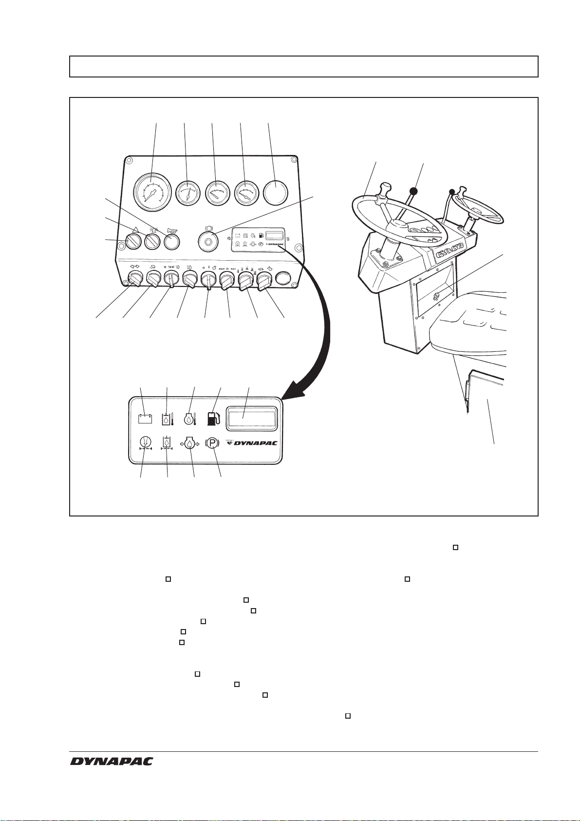
INSTRUMENTS AND CONTROLS
45678
10
9
13 14 15 16 17 18 19 20
1 2
1211
3
21 22 23 24 25
26 27 28 29
Fig. 6 Operator’s station
1. Steering wheel
2. Forward/reverse lever
3. Rev control
4. Tachometer
5. Fuel gauge
6. Instrument, coolant temperature
7. Instrument, hydraulic temperature
8. Instrument, voltmeter
9. Hazard flashers
10. Hazard beacon
11. Horn
12. Reserve/parking brake knob
13. Direction indicators
14. Light switch for working lights
15. Light switch for parking/dipped lights
30
16. Light switch for main beam
17. Start/Stop knob
18. Manual/Automatic sprinkler
19. Sprinkler timer
20. Gear selector low/high
21. Warning lamp for charging
22. Warning lamp for hydraulic temperature
23. Warning lamp for engine temperature
24. Warning lamp for low fuel level
25. Hourmeter
26. Warning lamp for air filter
27. Warning lamp for hydraulic filter
28. Warning lamp for oil pressure
29. Warning lamp for brake
30. Handbook compartment
CS 141 O141EN4
= Optional equipment
9
Page 12
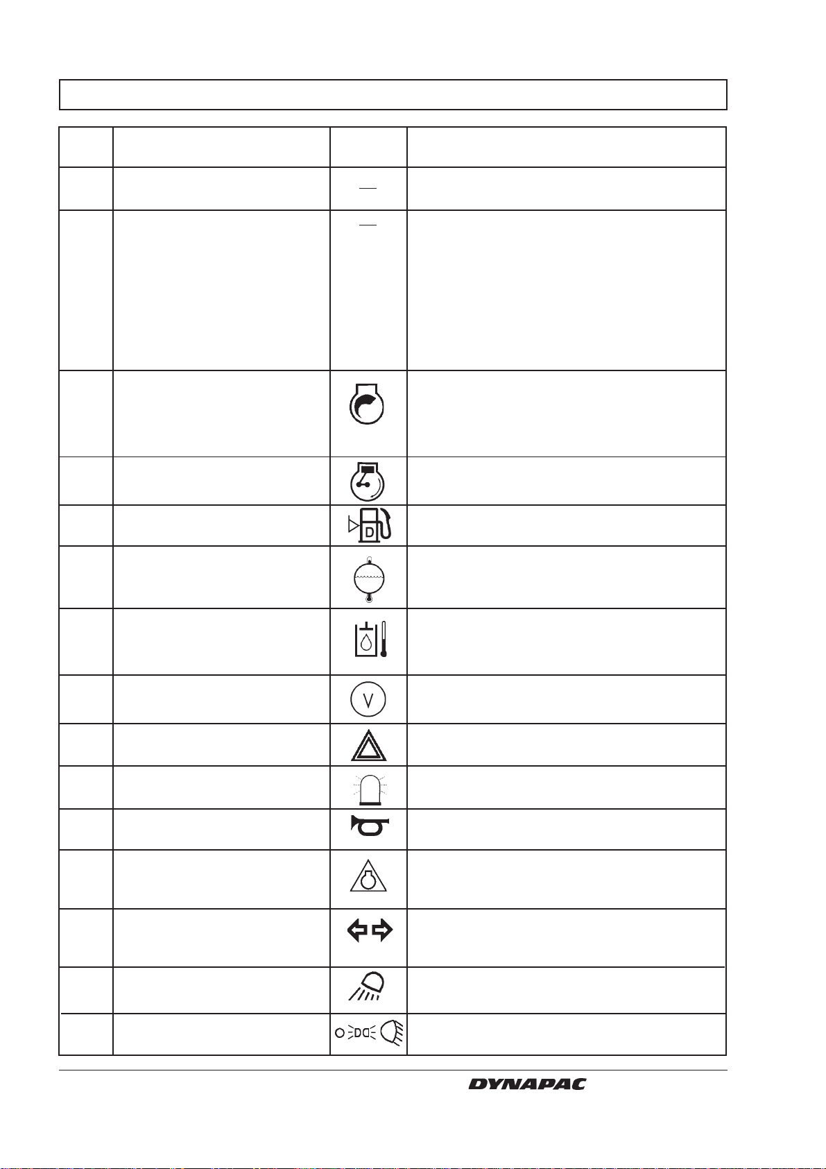
INSTRUMENTS AND CONTROLS, FUNCTIONAL DESCRIPTION
Items Designation Symbol Function
in fig. 6
1 Steering wheel There are two steering wheels, one on the left
and one on the right side.
2 Forward/reverse lever The lever must be in neutral to enable the
engine to start; the engine will not start if the
forward/reverse lever is in any other position.
The forward/reverse lever controls the driving
direction and speed of the roller. Move the
lever forward to drive the roller forward, etc.
The roller speed is proportional to the
movement of the lever from the neutral
position. The further from neutral, the higher
the speed.
3 Rev control, diesel engine Released/engaged by the center button. Pull
out the control to increase engine revs, push
it in to reduce revs. Turn/screw the handle for
fine adjustment. Turn counter-clockwise to
increase, clockwise to reduce.
4 Tachometer Indicates engine revs in revs per minute.
(Optional) Multiply the meter value by 100.
5 Fuel gauge Indicates level in the fuel tank.
6 Temperature gauge, coolant Indicates engine coolant temperature.
(Optional) Normal gauge reading: 82–93°C.
See engine manual.
7 Temperature gauge, Indicates the temperature of the hydraulic fluid.
hydraulic fluid (Optional) Normal value between 65 and 80°C (149–
176°F). Stop the roller if the value exceeds
85°C (185°F) and rectify the fault.
8 Voltmeter Indicates voltage of the electrical system.
(Optional) Normal indication is 12–15 volts.
9 Hazard flasher switch Turn right to switch on the hazard flashers.
(Optional)
10 Hazard beacon switch Turn right to switch on the hazard beacon.
(Optional)
11 Horn switch Press to sound the horn.
12 Reserve/parking brake knob Press to activate the reserve brake. Press
when the machine is stationary to activate the
STOP
parking brake. Pull out to release both brakes.
13 Direction indicator switch Turn left to switch on the left direction
(Optional) indicator, etc. The flashing indicator is OFF in
the middle position.
14 Light switch for working lights Turn right to switch on the forward working
lights.
15 Light switch for Turn right to switch on the parking lights and
parking/dipped lights further right to switch on the dipped headlights.
10
CS 141 O141EN4
Page 13
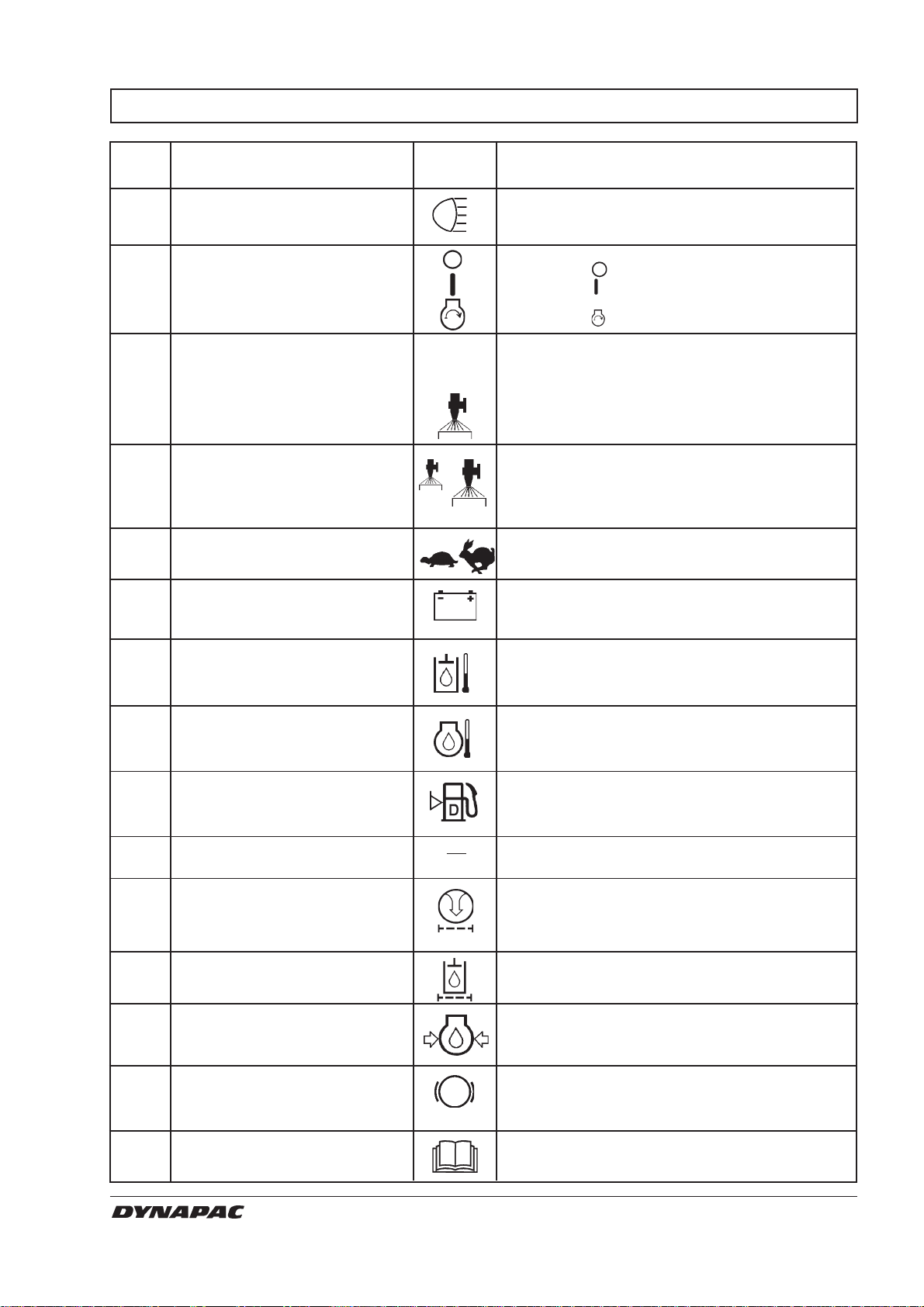
INSTRUMENTS AND CONTROLS, FUNCTIONAL DESCRIPTION
Items Designation Symbol Function
in fig. 6
16 Main beam/dipped lights The right position turns on the switch and the
switch (Optional) main beam light. The left position turns on the
dipped beam lights.
17 Starter switch In position
In position
the electric circuit is broken.
all instruments and electric
controls are powered.
In position
18 Sprinkler changeover switch In left position, continual timer watering is
MAN
O
AUTO
applied to the drums. In middle position,
watering is switched OFF. In right position,
the start motor is activated.
watering is switched on/off automatically via
the forward/reverse lever when the direction
of travel is changed.
19 Sprinkler time, switch The switch has six different timer modes to
(Optional) regulate the amount of water to the drums.
The left mode gives least water.
The right mode gives most water.
20 Gear selector, Tortoise = Working speed, low
low/high Hare = Transportation speed, high
21 Warning lamp for If the lamp lights while the engine is running,
battery charging the alternator is not charging. Stop the engine
and locate the fault.
22 Warning lamp for If the lamp lights, the hydraulic fluid is too hot.
hydraulic temperature Do not drive the roller; cool the fluid by
allowing the engine to idle and locate the fault.
23 Warning lamp for engine If the lamp lights, the engine is too hot. Stop
oil temperature the engine immediately and locate the fault.
See also the engine manual.
24 Warning lamp for low When the lamp lights, there is only enough
fuel level fuel left for a short distance. Refuel as soon
as possible.
25 Hourmeter Engine running time is indicated in hours.
26 Warning lamp for air cleaner The air cleaner must be cleaned or replaced if
the lamp lights while the engine is running at
full revs.
27 Warning lamp for If the lamp lights while the engine is running at
hydraulic filter full revs, the hydraulic filters must be changed.
28 Warning lamp for The lamp lights if engine oil pressure is too
oil pressure low. Stop the engine immediately and locate
the fault.
29 Brake warning lamp The lamp lights when the parking or reserve
brake knob is pushed in and the brakes are
applied.
30 Handbook compartment Storage space for the roller’s operator and
safety manuals.
CS 141 O141EN4
11
Page 14
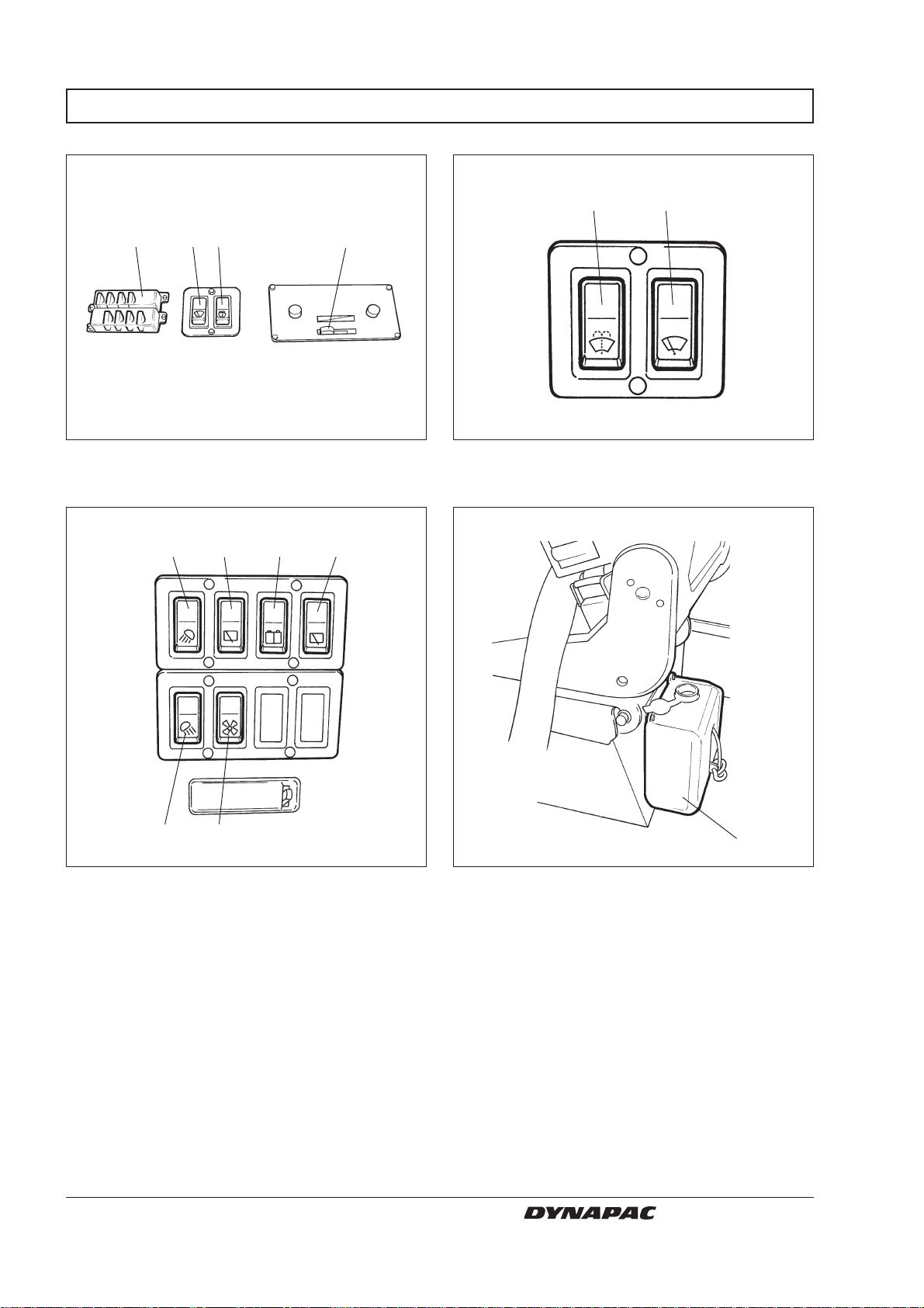
INSTRUMENTS AND CONTROLS, CAB (OPTIONAL)
8 7
9
Fig. 7a Cab roof, left side
6 8 10
1 354
Fig. 7b Cab roof, right side
2 11
Fig. 7c Cab roof, back
12
12
Fig. 7d Seat, left side
CS 141 O141EN4
Page 15
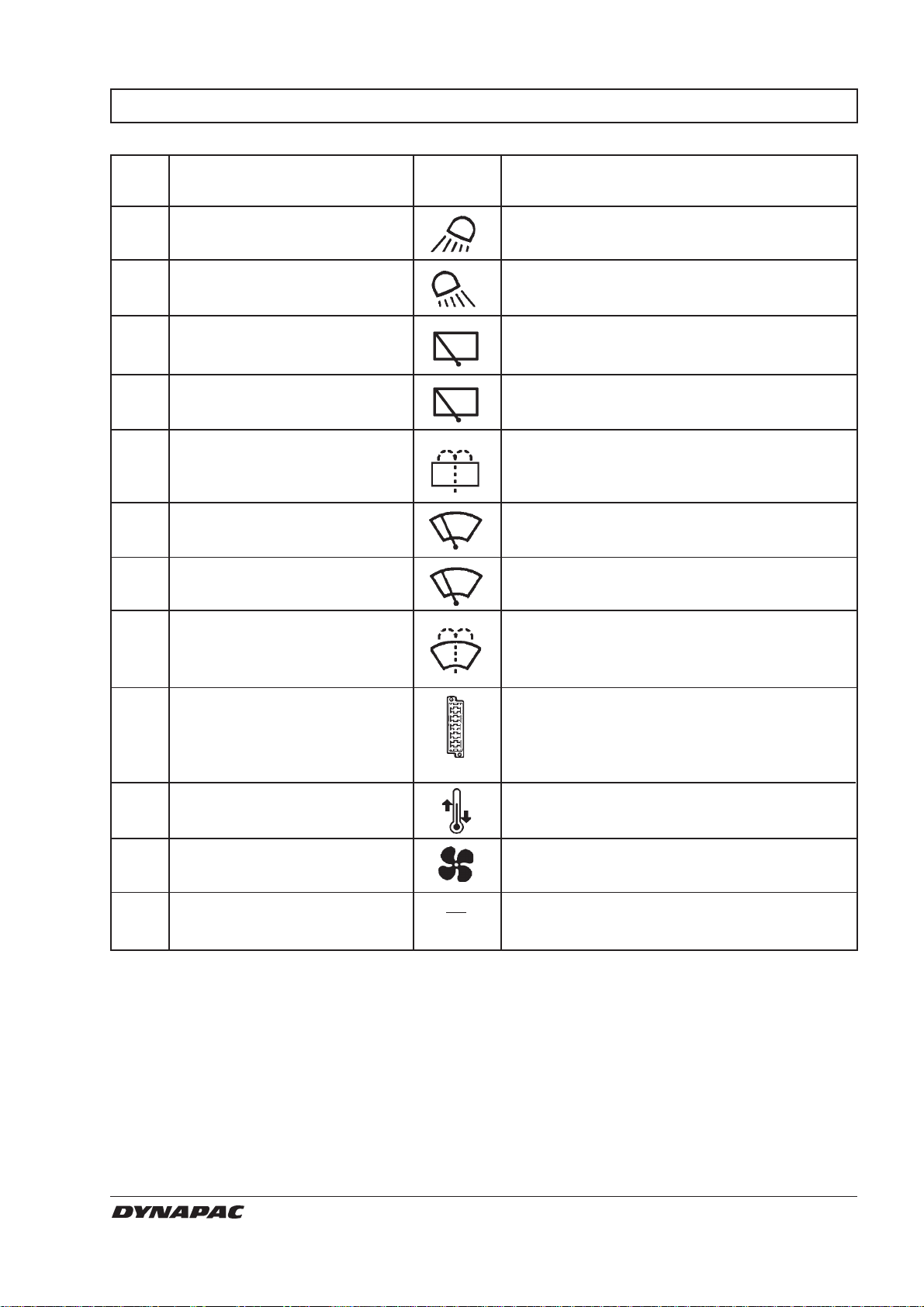
INSTRUMENTS AND CONTROLS IN CAB, FUNCTIONAL DESCRIPTION
Items Designation Symbol Function
in fig. 7
1 Front working light switch Press to switch on the front working lights.
2 Rear working light switch Press to switch on the rear working lights.
3 Left rear wiper Press to operate the rear wiper.
4 Right rear wiper Press to operate the rear wiper.
5 Rear windshield washer Press to wash the rear window.
switch
6 Left front wiper switch Press to operate the front windshield wiper.
7 Right front wiper switch Press to operate the front wiper.
8 SFront windshield washer Press to wash the front window.
switch
9 Fuse boxes (cab) Contains fuses for the cab electrical system.
See under the ”Electrical system” heading in
the Maintenance Manual for description of
function for the different fuses.
10 Heating control Left position = maximum heating.
Right position = heating is OFF.
11 Air fan switch Push to activate. Two positions for different
amounts of air.
12 Washer fluid container Fill with pure water and a small amount of
environmentally safe washer fluid.
CS 141 O141EN4
13
Page 16
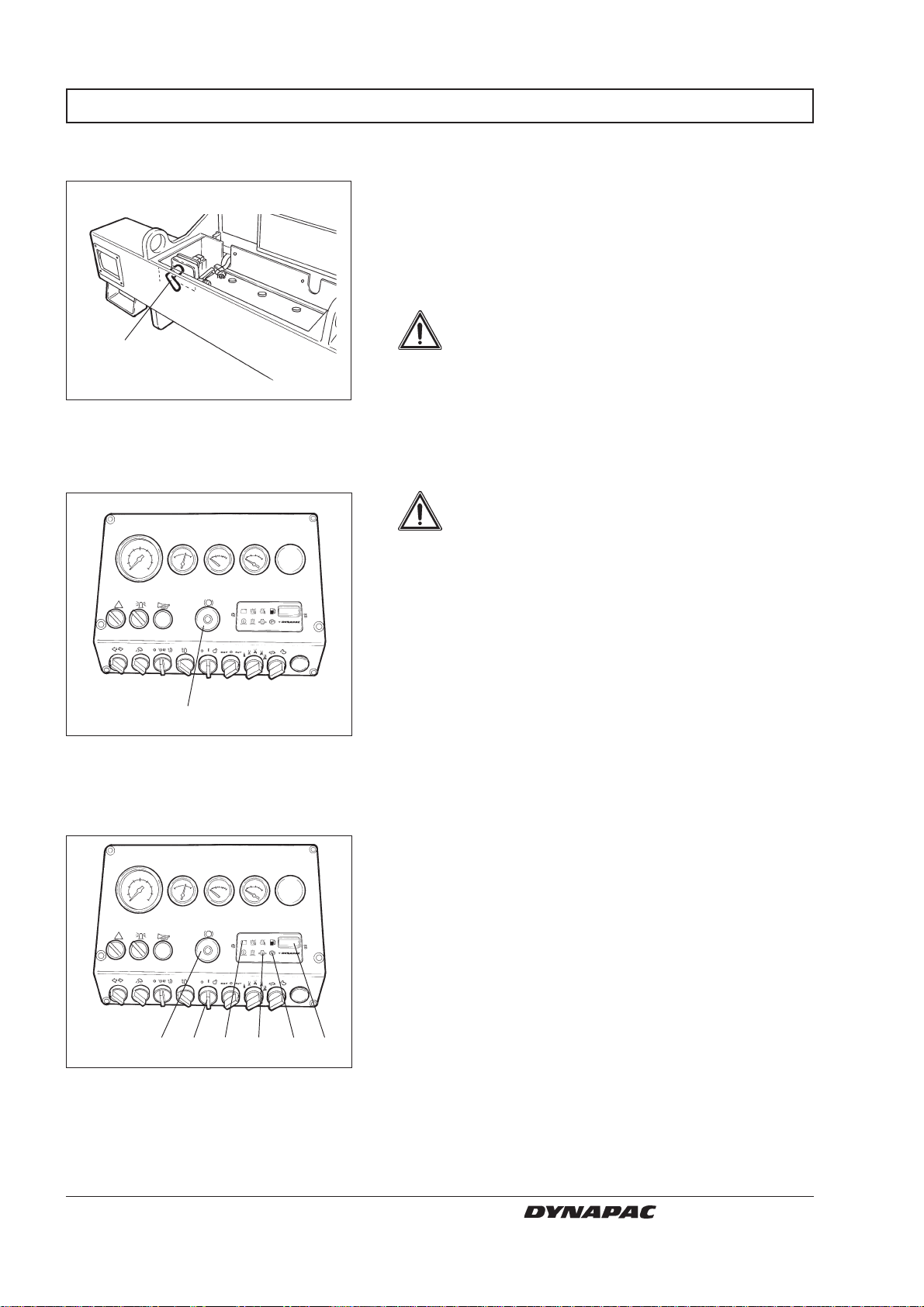
BEFORE STARTING
Battery disconnector
– Switching on
1
Fig. 8 Engine compartment
1. Battery disconnector
Reserve/parking brake
– Check
Remember to perform daily service. See the operation
manual.
The battery disconnector is located in the engine
compartment. Turn the key (1) to the ON position. The
entire roller is now powered.
WARNING
The engine hood must be unlocked during
operation, so that battery power can be
disconnected quickly if necessary.
WARNING
Make sure that the reserve/parking brake
knob (12) is pushed in. If the parking brake
is not applied, the roller may start to roll
when starting the engine on sloping ground.
12
Fig. 9 Starting controls
12. Reserve/parking brake knob
Instruments and lamps
– Checking
17
12 21
Fig. 10 Starting controls
12. Reserve/parking brake knob
17. Start/stop knob
21. Warning lamp for charging
25. Hourmeter
28. Warning lamp for oil pressure
29. Warning lamp for brake
28 29 25
Turn the starter switch (17) to position I. All warning
lamps should light for about 5 seconds and the buzzer
should sound. Make sure that the warning lamps light.
Check that the warning lamps for charging (21), oil
pressure (28) and parking brake (29) light.
The hourmeter (25) records the number of hours so
long as the engine is running.
14
CS 141 O141EN4
Page 17
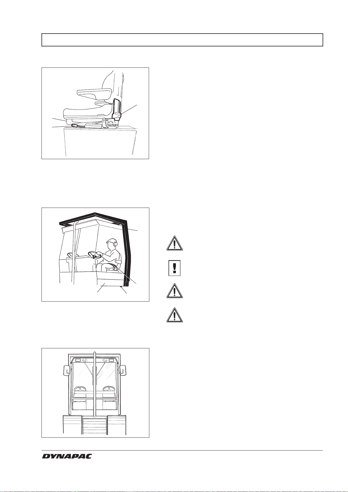
BEFORE STARTING
Operator’s seat – Setting
Set the operator’s seat in a comfortable position and so
that the controls are easily accessible.
The seat has the following adjustment features:
2
1
Fig. 11 Operator’s seat
1. Lever - length adjustment
2. Lever - backrest slope
3. Lever - weight adjustment
Operator’s station
4
Fig. 12 Operator’s station
1. Seat belt
2. ROPS
3. Rubber element
4. Anti-slip
3
Length adjustment (1)
Back slope adjustment (2)
Weight adjustment(3)
Always fasten the seat belt (1) that is provided if a
ROPS (Roll Over Protective Structure) is fitted on the
roller, and wear a protective helmet.
2
WARNING
Always replace the seat belt (1) with a new
one if it is worn or has been subjected to a
heavy load.
CAUTION
Check that rubber elements (3) on the platform
are intact. Worn elements will impair comfort.
WARNING
1
3
WARNING
Make sure that anti-slip (4) on the platform
is in good condition; replace with new antislip if friction is poor.
If the machine is fitted with a cab, make
sure that the door is closed when in motion.
View
Fig. 13 View
CS 141 O141EN4
Before starting, make sure that the field of view is
unobstructed, both in front and behind.
All cab windows must be clean and rear view mirrors
properly adjusted.
15
Page 18
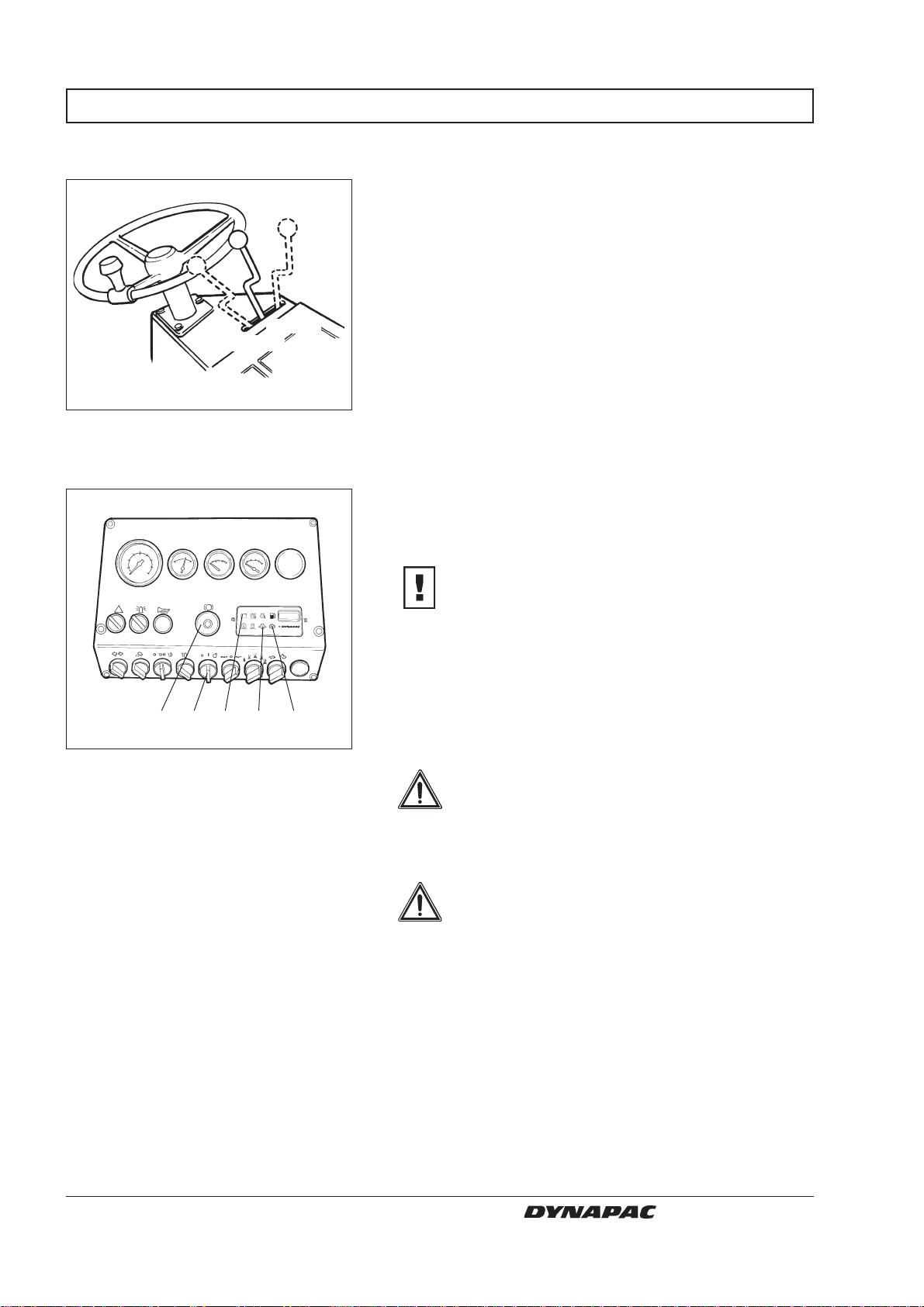
STARTING
Starting the engine
Reverse
Fig. 14 Forward/reverse lever
Instrument panel
Forward
Neutral
Put the forward/reverse lever in neutral. The engine
can only be started when the lever is in the neutral
position.
Press the button on the end of the throttle control and
pull out the throttle about ¼.
Turn the starter switch (17) to the right to the starting
mode and release the knob immediately when the
engine starts.
CAUTION
Do not run the starter motor too long; it is
better to wait a minute or so if the engine does
not start.
1712 21
Fig. 15 Starting controls
12. Reserve/parking brake knob
17. Start/stop knob
21. Warning lamp for charging
28. Warning lamp for oil pressure
29. Warning lamp for brake
28 29
Warm up the engine at idling speed for a few minutes,
longer if ambient temperature is below +10°C (50°F).
Check while warming up that the warning lamps for oil
pressure (28) and charging (21) are out. The warning
lamp (29) for the parking brake should still light.
WARNING
When you start up and drive a cold machine, the hydraulic fluid is cold and the
braking distance will be longer than normal
until the machine reaches normal working
temperature.
WARNING
Make sure that ventilation (extraction) is
adequate if the engine is run indoors. Risk
of carbon monoxide poisoning.
16
CS 141 O141EN4
Page 19
OPERATION
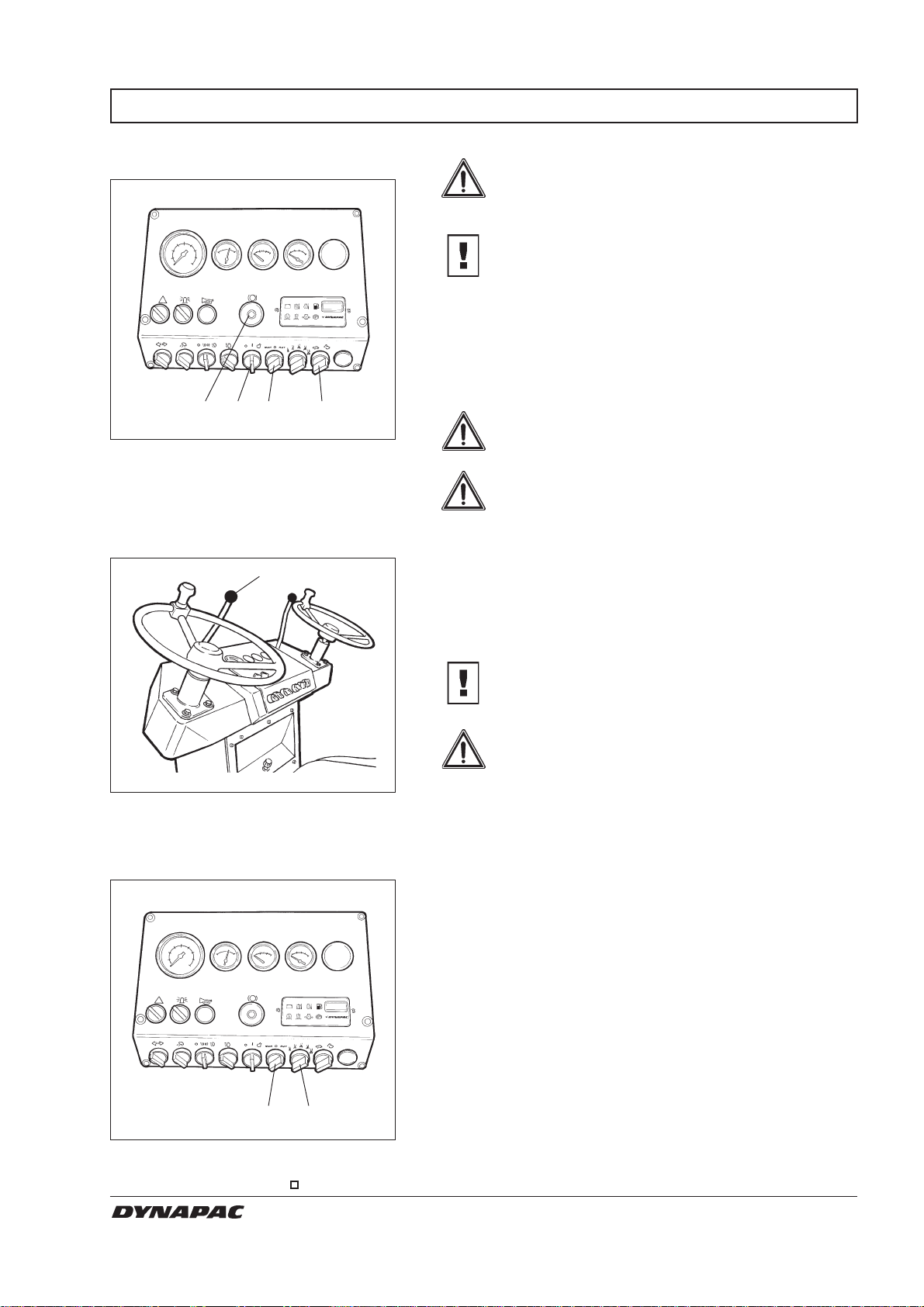
Driving the roller
1712 20
18
Fig. 16 Starting controls
12. Reserve/parking brake knob
17. Start/stop knob
18. Sprinkler switch
20. Gear selector
Instrument panel
WARNING
Under no circumstances may the machine
be operated from the outside. The operator
must remain seated inside the machine
during all operation.
CAUTION
Always drive with engine revs higher than 1500
r/min.
Increase engine revs to 1800 r/min for maximum driving
speed.
Check that the steering is working by turning the
steering wheel once to the right and once to the left,
while the roller is stationary.
WARNING
Make sure that the area in front of and
behind the roller is clear.
WARNING
Pull up the reserve/parking brake knob (38)
and check that the warning lamp for the
parking brake is out. When starting the
roller on a slope, be prepared that it may
begin to roll.
2
Set the gear selector (20) at ”Tortoise” and carefully
move the forward/reverse lever (2) in the desired
direction of travel. Speed increases as the lever is
moved farther from the neutral position.
Fig. 17 Instrument panel
2. Forward/reverse lever
Sprinkler system/Water tanks
18 19
Fig. 18 Sprinkler control
18. Sprinkler switch
19. Sprinkler timer
CAUTION
Speed must always be regulated with the
forward/reverse lever and never by changing
the engine speed.
WARNING
Test the reserve brake by pressing the
reserve/parking brake knob (12) while the
roller is running slowly forward.
Check now and then while driving that the gauges show
normal readings. In the event of abnormal values or if
the beeper sounds, immediately stop the roller and the
engine. Check and remedy any fault; see also the
maintenance manual and the engine manual. When
changing direction of travel, always stop the roller fully
before moving the forward/reverse lever to the opposite
direction. Use the ”Hare” mode for transport driving and
”Tortoise” for compaction.
Turn on the sprinkler switch (18) and wet the drums
thoroughly before driving/compacting on the course.
Choose amount of water with the sprinkler timer (19).
The roller are equiped with two water tanks, see
“Specifications” in the Maintenance manual for water
volume.
Also see Maintenance manual for filling/pumps/filter etc.,
and the following page regarding different settings for
the sprinklerpumps.
Make sure the scrapers are correctly adjusted on the
drums.
CS 141 O141EN4
17
Page 20
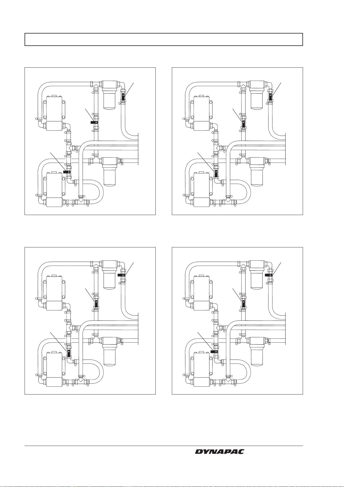
DRIVING
Basic setting
Closed
Closed
Fig. 19a Sprinkler system
Open
Two tanks – one pump (the lower)
Open
Open
Open
Fig. 19b Sprinkler system
One tank (the lower) – one pump
(the upper)
Open
Open
Fig. 19c Sprinkler system
Closed
One tank (the lower) – two pumps
Closed
Open
Closed
Fig. 19d Sprinkler system
Allow water from the upper tank to fill the lower
one, then close the tap before the filter.
18
Allow water from the upper tank to fill the lower
one, then close the tap before the filter.
CS 141 O141EN4
Page 21
BRAKING
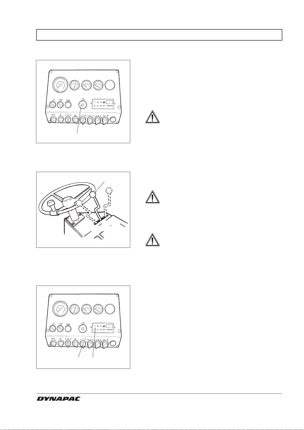
Reserve brake
Braking is normally done with the forward/reverse
lever. The hydrostatic transmission brakes the roller
when the lever is moved towards neutral.
In addition, a disc brake in each drum motor acts as
reserve brake when driving, and as a parking brake
when stationary.
WARNING
To brake, press the reserve/parking brake
knob (12), hold the steering wheel firmly
and be prepared for a sudden stop.
12
Fig. 20 Control panel
12. Reserve/parking brake knob
Normal braking
Fig. 21 Controls
2. Forward/reverse lever
Switching off
2
Neutral
Reverse
After braking, restore the forward/reverse lever to
neutral and pull up the reserve/parking brake knob.
Move the forward/reverse lever (2) to neutral to stop
the roller.
WARNING
Always press the reserve/parking brake
knob (12) even for brief stops when on
sloping ground.
Forward
Turn the speed control back to idling, allow the engine
to idle a 5 minutes to cool down.
WARNING
When you start up and drive a cold machine, the hydraulic fluid is cold and the
braking distance will be longer than normal
until the machine reaches normal working
temperature.
Check instruments and warning lamps to see if any
faults are indicated, switch off all lights and other electrical functions.
17 21-29
Fig. 22 Control panel
17. Starter switch
21-29. Panel for warning lamps
CS 141 O141EN4
Turn the starter switch (17) to mode O. Lower the
instrument cover (on rollers without cab) and lock it.
19
Page 22
PARKING
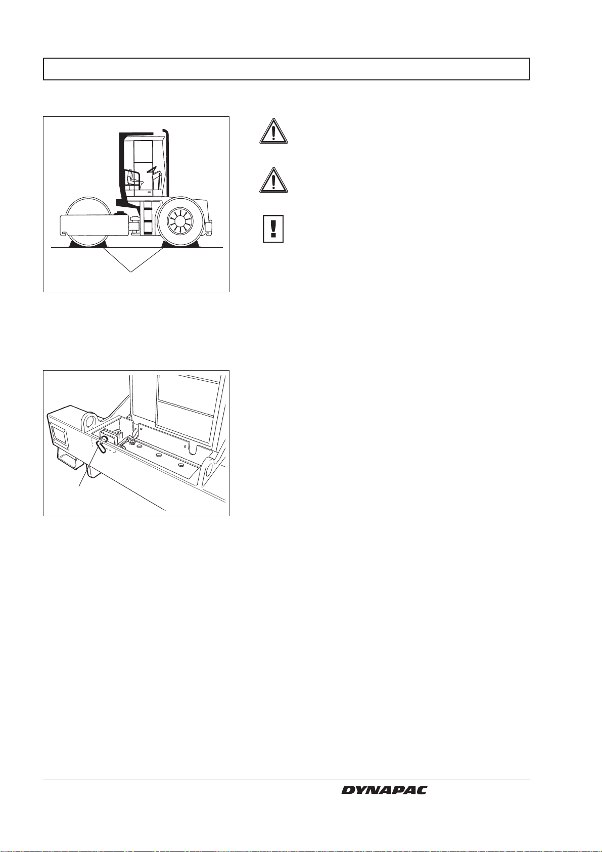
Chocking the drum
1
Fig. 23 Arrangement
1. Chock
Battery disconnector
WARNING
Never leave the roller with the engine running without pressing in the reserve/parking brake knob.
WARNING
Make sure that the roller is parked in a safe
place for traffic. Chock the drums if the
roller is parked on sloping ground.
CAUTION
Remember the risk of freezing during the
winter. Use suitable antifreeze in the engine
cooling system and in the washer fluid container in the cab. Empty the water tanks, pumps
and leads.
Switch the battery disconnector (1) into disconnected
mode and remove the key before leaving the roller.
1
Fig. 24 Engine compartment
1. Battery disconnector
This will prevent battery discharge and will also make it
difficult for any unauthorized person to start and drive
the machine. Also lock the doors to the engine
compartment.
20
CS 141 O141EN4
Page 23
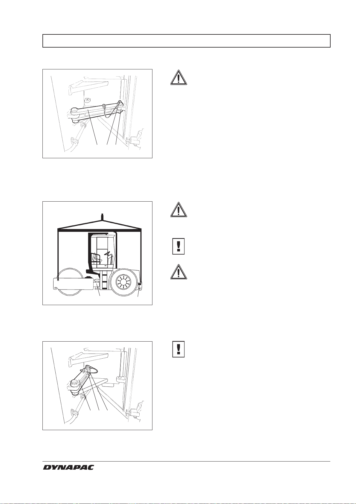
LIFTING
Locking the articulated joint
2 4
3
Fig. 25 Articulation in interlocked mode
2. Locking pin
3. Locking arm
4. Locking lug, front
Lifting the roller
Weight: see lifting plate on the roller
WARNING
Articulation must be locked to prevent
inadvertent turning before lifting the roller.
Turn the steering wheel so that the machine is set for
driving straight forward. Push in the reserve/parking
brake knob.
Pull up the locking pin (2), provided with wire.
Fold out the locking arm (3) and secure it to the upper
locking lug (4) on the front of the machine frame.
Insert the locking pin through the holes in the locking
arm and locking lug.
WARNING
The gross weight of the machine is noted
on the lifting plate (2). See also technical
specifications in the maintenance instructions.
CAUTION
Lifting gear, such as chains, steel wires,
straps, and lifting hooks must be dimensioned
in conformance with current regulations.
WARNING
Keep well clear of the lifted machine! Make
sure that lifting hooks are securely anchored.
1
Fig. 26 Lifting the roller
1. Articulation lock
2. Lifting plate
2
Releasing the articulated joint
2 4
3
Fig. 27 Articulation in open mode
2. Locking pin
3. Locking arm
4. Locking lug, rear
CS 141 O141EN4
CAUTION
Remember to restore the articulation interlock
to open mode before driving again.
Fold back the locking arm (3) and secure it in the
locking lug (4) with the locking stud (2). The locking lug
is located on the front frame of the machine.
21
Page 24
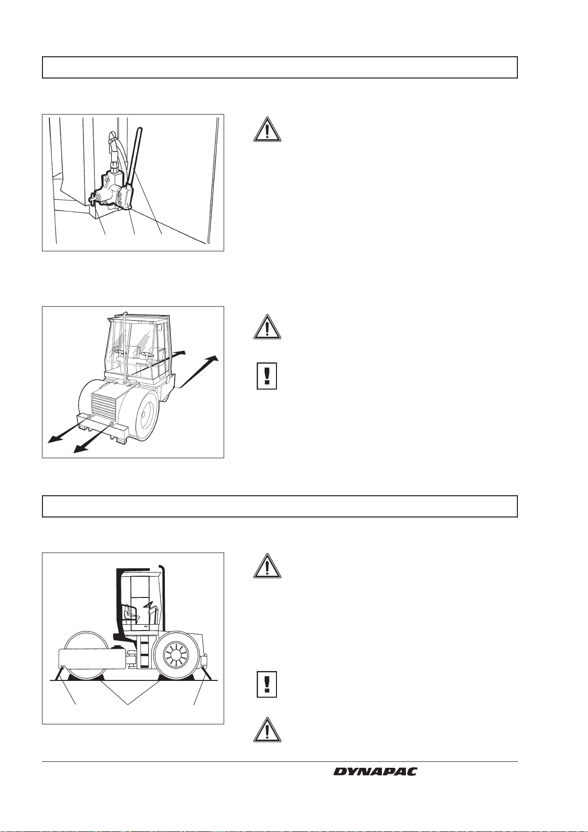
TOWING
Towing
132
Fig. 28 Brake disengagement pump
1. Valve
2. Pump arm
3. Pump
WARNING
Chock the drums to prevent the roller from
moving when the brakes are hydraulically
disengaged.
First, open both of the towing valves according to
alternative 1 above.
The disengagement pump for the brakes is located
behind the right door to the engine compartment.
Make sure that the valve (1) is pushed in and pump
with the pump arm (2) until the brakes are disengaged.
When restoring, hold the valve (1) in the extended
position for a few seconds.
WARNING
The roller must be counter-braked when
towing. Use a towbar because the roller will
have no ability to brake.
CAUTION
The roller must be towed slowly, max. 3 km/h
(2 mph) and for a short distance only, max. 300
m (330 yards).
Fig. 29 Towing
TRANSPORT
Roller prepared for transportation
212
Fig. 30 Transportation
1. Chock
2. Lashing wire
When a machine is towed/retrieved, the towing device
must be connected to both lifting holes. Pulling forces
shall act longitudinally on the machine as illustrated.
Maximum gross pulling force 60 kN (13.5 lbf).
WARNING
Interlock the articulation before hoisting
and transportation. Follow the instructions
under the respective heading.
Chock the drums (1) and secure the chocks to the
transport vehicle.
Clamp down the roller with lashing strap (2) at all four
corners; decals indicate the fixing points.
CAUTION
Remember to restore the articulation interlock
to its open mode before starting the roller
again.
WARNING
The roller must be unoccupied during
transportation.
22
CS 141 O141EN4
Page 25
OPERATING INSTRUCTIONS - SUMMARY
WARNING
1. Follow the SAFETY INSTRUCTIONS in the Safety Manual.
2. Make sure that all instructions in the maintenance manual are followed.
3. Turn the battery disconnector to on.
4. Put the forward/reverse lever in neutral.
5. Set the revs control to the idling mode.
6. Start the engine and allow it to warm up.
7. Set the revs control in the operating mode.
WARNING
8. Drive the roller. Operate the forward/reverse lever with care.
WARNING
WARNING
9. Test the brakes.
Remember that the braking distance will be longer if the roller is cold.
10. Make sure that the drums are watered sufficiently when needed.
11. IN AN EMERGENCY: - Push in the reserve/parking brake knob.
- Hold the steering wheel firmly.
- Brace yourself for a sudden stop.
12. Parking: Push in the reserve/parking brake knob.
Stop the engine and chock the drums.
13. Lifting: - See the operation manual.
14. Towing: - See the operation manual.
15. Transport: - See the operation manual.
16. Retrieval: - See the operation manual.
CS 141 O141EN4
23
 Loading...