


RCEM
Table of contents
 Loading...
MODEL RCEM
PORTABLE FLEXIBLE VERSION
RECTIFIER MONITORING SYSTEM
Installation, Operation and Service Manual
Manual Item No. 043756
Rev. G
DynAmp, LLC 3735 Gantz Road Phone +1 614.871.6900 www.dynamp.com
Grove City, Ohio 43123 USA Fax +1 614.871.6910 help@dynamp.com

Installation, Operation and Service Manual RCEM
This Page is Intentionally Blank
© 2012 DynAmp, LLC Page ii
43756 G

Installation, Operation and Service Manual RCEM
DynAmp, LLC WARRANTY
Items and components manufactured by Seller for permanent installation are warranted for
two (2) years from the date of shipment.
Items and components manufactured by Seller for portable and temporary use in more
than one location are warranted to be free from defects in material and workmanship for a
period of eighteen (18) months from the date of shipment.
Items and components not manufactured and resold by Seller are warranted by their
manufacturer.
Warranty repair shall be, at DynAmp's option, in the form of repair or replacement of the
defective items or components. Concerning warranty repairs, DynAmp will be responsible
for DynAmp provided time, material and transportation costs (shipping or travel). Actual
method of warranty repair / correction will be determined by DynAmp at DynAmp's sole
option. Such warranty repair shall constitute a fulfillment of all DynAmp, LLC liabilities in
respect to said items and components. In no event shall DynAmp, LLC be liable for
consequential damages.
Information in this document is subject to change without notice.
© 2001, 2003, 2004, 2006, 2011, 2012 DynAmp, LLC. All rights reserved.
Reproduction for purposes other than operation and service without written permission of DynAmp, LLC
is strictly forbidden.
This manual includes detailed drawings, installation, operation, service and maintenance. Users should
evaluate the information in the manual and their particular application. DynAmp assumes no liability for
any incidental, indirect, or consequential damages arising fro the use of this documentation.
While all information presented is believed to be reliable and in accordance with accepted engineering
practices, DynAmp makes no warranties as to the completeness of the information.
© 2012 DynAmp, LLC Page iii
43756 G

Installation, Operation and Service Manual RCEM
This Page is Intentionally Blank
© 2012 DynAmp, LLC Page iv
43756 G
Installation, Operation and Service Manual RCEM
VOLTAGE
INSTALLATION
Hazard Warning!
GENERAL
HAZARDOUS
Qualified technicians who are familiar with the warnings and instructions of
this manual must perform all installation, maintenance and service.
Disconnect power to the system before servicing or replacing fuses.
Use of the equipment in a manner not specified by the manufacturer can
impair the protection provided within.
DynAmp does not assume liability for the customer’s failure to comply with the
rules and requirements provided in this manual.
This equipment is designed to be connected to hazardous electric voltages.
Ignoring the installation precautions and warnings can result in severe
personal injury or equipment damage.
To avoid the risk of electrical shock or fire, the safety instructions and
guidelines in this manual must be followed. The electrical specifications must
not be exceeded and the unit must be installed according to directions
provided.
This equipment is intended for indoor use only. It should be mounted in a
well-ventilated area, away from high heat, dust, and corrosive atmosphere.
The ambient temperature must not exceed 55°C.
The laptop computer must be located well away from magnetic fields. Failure
to comply may result in damage to the computer.
For mounting considerations that fall outside the recommended specifications
provided in this manual, the factory should be contacted for approval.
This unit is rated for installation category III, 300V and pollution degree 2.
Symbol Identification:
General definitions of safety symbols used on equipment and manual.
© 2012 DynAmp, LLC Page v
43756 G
Caution/Warning: Refer to accompanying documents for instructions.

Installation, Operation and Service Manual RCEM
This Page is Intentionally Blank
© 2012 DynAmp, LLC Page vi
43756 G

Installation, Operation and Service Manual RCEM
DynAmp, LLC Customer Support
For further assistance, contact DynAmp Customer Support at:
Americas:
Telephone: +1 614.871.6900 Fax: +1 614.871.6910
8:00 AM to 5:00 PM USA Eastern Time
From first Sunday in November to second Sunday in March – 13:00 GMT to 22:00 GMT
From second Sunday in March to first Sunday in November – 12:00 GMT to 21:00 GMT
Europe:
Telephone: +41 22.706.1446 Fax: +41 22.706.1311
8:30 AM to 5:00 PM Central European Time
From last Sunday in October to last Sunday in March – 7:30 GMT to 16:00 GMT
From last Sunday in March to last Sunday in October – 6:30 GMT to 15:00 GMT
After Hours Critical Service Emergency:
Telephone: +1 614.871.6906
5:00 PM to 8:00 AM USA Eastern Time
From first Sunday in November to second Sunday in March – 22:00 GMT to 13:00 GMT
From second Sunday in March to first Sunday in November – 21:00 GMT to 12:00 GMT
Central e-mail:
help@dynamp.com
DynAmp web:
www.dynamp.com
© 2012 DynAmp, LLC Page vii
43756 G

Installation, Operation and Service Manual RCEM
This Page is Intentionally Blank
© 2012 DynAmp, LLC Page viii
43756 G

Installation, Operation and Service Manual RCEM
Page
Rev
Reason For Revision
Date
All
NEW
06/01
23,
A
Add Integrator PC Board calibration procedure and Update
10/01
37
B
Revise Appendix B-2: Minimum Requirements for Laptop
10/03
45-54
C
ECO-3099 - Revise Appendix B: Add Devices/Leg
08/04
45-54
D
Update to DynAmp, LLC, ECO-3102 – Revise Appendix B:
12/04
v, 1, 27,
36
E
Update fuse precautions per ECR 1304
07/06
Intervals / New Manual Format
/Software requirments
REVISION PAGE
37-46
all F
35, 45 G
Appendix B to revised spreadsheets
Computer
Command Button
Add ANSI Rectifier Circuit select
PAR 10245 – Handling & Storage, ECR 1440- Calibration
ECR1683 - Revise Spare Parts List, Table 8.1, Computer
06/11
03/12
© 2012 DynAmp, LLC Page ix
43756 G

Installation, Operation and Service Manual RCEM
This Page is Intentionally Blank
© 2012 DynAmp, LLC Page x
43756 G

Installation, Operation and Service Manual RCEM
TABLE OF CONTENTS
Par. Title Page
1. SAFETY ____________________________________________________________ 1
1.1 O
VERVIEW ............................................................................................................................. 1
2. HANDLING AND STORAGE ____________________________________________ 3
3. DESCRIPTION _______________________________________________________ 5
3.1 G
3.2 D
3.3 D
3.4 L
3.5 F
3.6 M
ENERAL ............................................................................................................................... 5
EFINITIONS........................................................................................................................... 5
ATA ACQUISITION UNIT ......................................................................................................... 5
APTOP COMPUTER ................................................................................................................ 6
LEXIBLE CURRENT SENSORS ................................................................................................. 6
AGNETIC FIELD STATEMENT .................................................................................................. 6
4. SPECIFICATIONS ____________________________________________________ 7
5. TECHNICAL DESCRIPTION ____________________________________________ 9
5.1 G
5.2 B
5.3 A
5.4 B
5.5 P
5.6 A
5.7 I
5.8 R
5.9 T
5.10 P
5.11
5.12 D
ENERAL ............................................................................................................................... 9
ASIC THEORY OF OPERATION ............................................................................................... 9
NALOG CARD RACK .............................................................................................................. 9
ACKPLANE ......................................................................................................................... 10
OWER CIRCUITS ................................................................................................................. 10
NALOG INPUT CONNECTORS ............................................................................................... 11
NTEGRATOR CARDS ............................................................................................................. 11
ESET SYNC CARDS ............................................................................................................. 12
EST SIGNAL GENERATOR .................................................................................................... 13
ERSONAL DAQ/56 ............................................................................................................... 14
USB EXTENDER RECEIVER .................................................................................................. 15
IGITAL INTERFACE MODULE ................................................................................................. 15
6. PREPARATION FOR USE _____________________________________________ 17
6.1 S
6.2 R
6.3 S
6.4 I
YSTEM CHECKOUT AND PREPARATION ................................................................................. 17
ECTIFIER SHUTDOWN ......................................................................................................... 17
ENSOR MOUNTING AND CONNECTION CONSIDERATIONS ....................................................... 17
NSTALLATION INSTRUCTIONS ................................................................................................ 17
7. MAINTENANCE AND TROUBLESHOOTING ______________________________ 27
7.1 C
7.2 G
7.3 V
7.4 F
7.5 S
7.6 V
7.7 A
7.8 A
7.9 S
7.10 S
7.11 C
7.12 R
© 2012 DynAmp, LLC Page xi
43756 G
ALIBRATION INTERVALS ....................................................................................................... 27
ENERAL ............................................................................................................................. 27
ERIFYING PROPER OPERATION ............................................................................................ 27
USE REPLACEMENT ............................................................................................................ 28
TATIC PRECAUTIONS WHEN SERVICING ............................................................................... 28
ERIFYING PROPER INTEGRATOR RESET SYNCHRONIZATION .................................................. 29
DJUSTING THE SIGNAL GENERATOR ..................................................................................... 29
DJUSTING THE INTEGRATOR PC BOARDS....................................................................... 30
ENSOR TESTING (CONTINUITY METHOD) .............................................................................. 30
ENSOR DIELECTRIC TESTING - WINDINGS TO SURFACE ........................................................ 31
ONNECTOR CONTAMINATION (INTEGRATOR CARDS) .............................................................. 32
ESET SYNC ERROR OR INCORRECT DATA ............................................................................ 33

Installation, Operation and Service Manual RCEM
8. SERVICE, PARTS, AND DOCUMENTATION ______________________________ 35
8.1 SERVICE
8.2 S
8.3 S
PARE PARTS ORDERS - ROUTINE OR EMERGENCY ................................................................ 36
PARE PARTS ...................................................................................................................... 36
ASSISTANCE ..................................................................................................... 35
9. DRAWING LIST _____________________________________________________ 37
9.1
REQUIRED DRAWINGS ............................................................................................................. 37
APPENDIX A: ANSI RECTIFIER CIRCUITS __________________________________ 39
APPENDIX B: SOFTWARE _______________________________________________ 45
B.1 P
B.2 M
B.3 S
B.4 S
B.5 S
B.6 PROGRAMMING
B.7 SEL
B.8 A
B.9 S
B.10 A
B.11 STARTING
B.12 STOPPIN
B.13 V
B.14 R
B.15 CALIBRATE
B.16 P
ROVIDED SOFTWARE .......................................................................................................... 45
INIMUM REQUIREMENTS FOR LAPTOP COMPUTER ................................................................ 45
OFTWARE INSTALLATION ..................................................................................................... 45
TARTING THE DATA ACQUISITION PROGRAM ......................................................................... 46
PREADSHEET DESCRIPTION ................................................................................................ 47
THE NUMER OF DEVICES/LEG ............................................................ 48
ECTING THE ANSI RECTIFIER CIRCUIT NUMBER .................................................................. 48
CQUIRING A RECTIFIER DATA SET ........................................................................................ 49
AVING THE RECTIFIER DATA TO A DISK FILE ......................................................................... 49
CTIVATING THE TEST MODE OF OPERATION ......................................................................... 49
THE SCAN MODE OF OPERATION ................................................................ 49
G THE SCAN MODE OF OPERATION ....................................................................... 50
IEWING THE DIODE CURRENT BAR GRAPHS ........................................................................... 50
ECOVERING FROM DAQ ERRORS ......................................................................................... 50
WORKSHEET ................................................................................................ 51
RECAUTIONS ...................................................................................................................... 51
FIGURES
Figure # Title .................................................................................................. Page
Figure 5.1 Analog Card Rack ................................................................................................ 10
Figure 5.2 Reset Pulse Connector Location .......................................................................... 13
Figure 5.3 Reset Pulse Signal Location ................................................................................. 13
Figure 5.4 571A Test Signal Waveform................................................................................. 14
Figure 5.5 Personal Daq/56 .................................................................................................. 14
Figure 5.6 USB Extender Receiver ........................................................................................ 15
Figure 5.7 Digital Interface Module ........................................................................................ 15
Figure 6.1 Flexible Current Sensor Installation Detail ............................................................ 18
Figure 7.1 Device Current Waveform .................................................................................... 29
Figure 7.2 Reset Sync PC Board .......................................................................................... 30
Figure 7.3 Integrator PC Board ............................................................................................. 30
Figure 7.4 Hi-Pot Test Setup ................................................................................................. 32
Figure A.1 ANSI Rectifier Circuit 23 ...................................................................................... 39
Figure A.2 ANSI Rectifier Circuit 24 ...................................................................................... 39
Figure A.3 ANSI Rectifier Circuit 25 ...................................................................................... 40
Figure A.4 ANSI Rectifier Circuit 26 ...................................................................................... 40
Figure A.5 ANSI Rectifier Circuit 31 ...................................................................................... 41
Figure A.6 ANSI Rectifier Circuit 32 ...................................................................................... 41
Figure A.7 ANSI Rectifier Circuit 45 ...................................................................................... 42
Figure A.8 ANSI Rectifier Circuit 46 ...................................................................................... 42
Figure A.9 ANSI Rectifier Circuit 52 ...................................................................................... 43
Figure B.1 6Leg120Ch Spreadsheet ..................................................................................... 52
© 2012 DynAmp, LLC Page xii
43756 G

Installation, Operation and Service Manual RCEM
Figure B.2 M6Leg120Ch Spreadsheet ................................................................................... 52
Figure B.3 12Leg120Ch Spreadsheet ................................................................................... 53
Figure B.4 1Leg-20ch Spreadsheet ....................................................................................... 53
Figure B.5 Leg 1 Bar Chart ................................................................................................... 54
Figure B.6. Calibrate Worksheet ........................................................................................... 54
TABLES
Table # Title .................................................................................................. Page
Table 4.1 Rectifier Condition Evaluation Monitor Specifications .............................................. 7
Table 4.1 Rectifier Condition Evaluation Monitor Specifications (Continued) ........................... 8
Table 6.1 Transducer Connections, 6-Leg Rectifier (20 Diodes Max.).................................... 19
Table 6.2 Transducer Connections, 6-Leg Rectifier (40 Diodes Max.)................................... 20
Table 6.3 Transducer Connections, Parallel 6-Leg Rectifier (10 Diodes Max) ........................ 21
Table 6.4 Transducer Connections, Parallel 6-Leg Rectifier (20 Diodes Max) ....................... 22
Table 6.5 Transducer Connections, 12-Leg Rectifier (10 Diodes Max.) ................................. 23
Table 6.6 Transducer Connections, 12-Leg Rectifier (20 Diodes Max.) ................................. 24
Table 6.7 Transducer Connections, 1-Leg of a Multi-Leg Rectifier ......................................... 25
Table 8.1 Spare Parts List ..................................................................................................... 36
Table 9.1 Drawing List ........................................................................................................... 37
© 2012 DynAmp, LLC Page xiii
43756 G

Installation, Operation and Service Manual RCEM
This Page is Intentionally Blank
© 2012 DynAmp, LLC Page xiv
43756 G

Installation, Operation and Service Manual RCEM
1. SAFETY
1.1 OVERVIEW
This equipment is designed to be connected to hazardous electric voltages. Ignoring the
installation precautions and warnings can result in severe personal injury or equipment
damage. The following are general guidelines that should be followed when installing,
operating and servicing the RCEM.
• Qualified technicians who are familiar with the warnings and instructions of this manual
must perform all installation, maintenance and service.
• Always follow all local and plant safety procedures.
• The equipment covers should remain closed at all times during operation to ensure
safety of personnel. Only authorized personnel or technicians should be allowed to
open and service the equipment.
• Cover #3 (PC Board Cover) may be removed if the operator needs access to the diode
waveform connectors. Use caution whenever the cover is removed.
• Only qualified technicians should perform Service. If use of an oscilloscope becomes
necessary during operation or servicing, either the scope must be floating or
ungrounded, or differential probe(s) must be used. The equipment is isolated from the
mains via the power transformers. If a grounded scope is used, a hazardous condition
is created since current will flow through the probe to ground.
• Replace fuses with correct type, size and value. Refer to the servicing instructions or
spare parts list for more information on replacement fuses. Do not bypass the fuses or
modify the electronics. Disconnect power to the system before replacing fuses. Failure
to follow these instructions will result in intermittent operation and premature failure and
will void the warranty.
• The equipment is not intrinsically safe. Do not place in explosive atmospheres.
• The Current Transducers are double insulated to protect the operator from possible
hazardous voltage potentials of the rectifier. The transducers are also protected from
heat by a protective sheath.
• Make sure the transducer cables and interconnection cables are kept well away from
hazardous voltage potentials and heat sources inside the rectifier.
• Keep the electronics enclosure as far as possible away from the hazardous voltage
potentials of the rectifier.
• Use of the equipment in a manner not specified by the manufacturer can impair the
protection provided.
DynAmp does not assume liability for the customer’s failure to comply with the rules and
requirements provided in this manual.
© 2012 DynAmp, LLC Page 1
43756 G

Installation, Operation and Service Manual RCEM
This Page is Intentionally Blank
© 2012 DynAmp, LLC Page 2
43756 G

Installation, Operation and Service Manual RCEM
2. HANDLING AND STORAGE
DynAmp products are engineered and manufactured for use in industrial environments.
However, they contain sensitive electronic and mechanical components which may be
damaged and fail if not handled and stored properly. All products must be handled and
stored with the same care as any precision measurement instrument. Severe bumps or
jolts may damage internal parts and cause malfunction or premature failure. DynAmp
products are designed and assembled with conformal coating, shock mounting, and
environmental seals, when appropriate or when specified. However, this protection
requires that the product must be properly installed and operational before the protection is
fully functional. Therefore, adequate protection from humidity, shock, and temperature
must be provided during handling and storage prior to installation.
The handling and storage of equipment must be sufficient to meet the storage temperature
and humidity specifications of the product and to prevent any condensation or contact with
water or any other liquid. The storage location and container or crate must provide
adequate protection from precipitation (rain, snow, ice) and direct water contact. Adequate
shelter must be provided to prevent the accumulation of precipitation (rain, snow, ice) and
water which can lead to the deterioration or failure of shipping containers or crates and
cause water ingress. Storage in coastal or industrial areas subject to salt-laden or
corrosive air or areas of wind-driven sand or other abrasive dust must be adequate to
prevent the deterioration or failure of shipping containers or crates and cause ingress.
Frequent inspection of storage areas and storage containers or crates is required to ensure
proper storage conditions are being maintained.
If the shipping container or crate is opened and/or the equipment is removed for inspection
prior to installation, the equipment must be repackaged in the original undamaged
container or crate in the same manner as it was shipped to prevent environmental damage
or placed in a storage location that meets the required environmental and storage
conditions.
General product storage temperature and humidity requirements:
Storage Temperature: -40 to 70°C
-40 to 158°F
Storage Humidity: 85%, non-condensing
DynAmp, LLC does not assume liability for the customer’s failure to comply with handling
and storage requirements.
For further assistance, contact DynAmp customer support.
© 2012 DynAmp, LLC Page 3
43756 G

Installation, Operation and Service Manual RCEM
This Page is Intentionally Blank
© 2012 DynAmp, LLC Page 4
43756 G

Installation, Operation and Service Manual RCEM
Channel
Flexible Current Sensor and associated electronic circuitry
DAU
Abbreviation for Data Acquisition Unit; rectifier monitoring system
Device
Rectifier semiconductor device (such as a diode or thyristor).
Current Sensor
DynAmp Flexible Current Sensor
I/O
Input/Output device.
Laptop Computer
Portable computer used to display the rectifier data
Leg
Group of rectifier devices connected in parallel. Symbolically
Multiplexer
The binary address that selects one-of-six integrator card leg
USB
Universal Serial Bus
RCEM
DynAmp Rectifier Condition Evaluation Monitor
RMS
root mean square – Effective value of a waveform
3. DESCRIPTION
3.1 GENERAL
The DynAmp RECTIFIER MONITORING SYSTEM Model RCEM is designed for isolated
measurement of device currents in multiple path power rectifiers.
Model RCEM is a monitoring system composed of a 120 Channel Data Acquisition Unit, a
laptop computer, Flexible Current Sensors, and the interconnection cables.
A 240 Channel RCEM is also available. This system consists of two 120 Channel Data
Acquisition Units, a laptop computer, LEM~flex Current Transducers, and interconnection
cables.
3.2 DEFINITIONS
The following terms are used extensively in this manual:
Address
active electronics hardware
referred to as R or S in ANSI circuit diagrams
output signals.
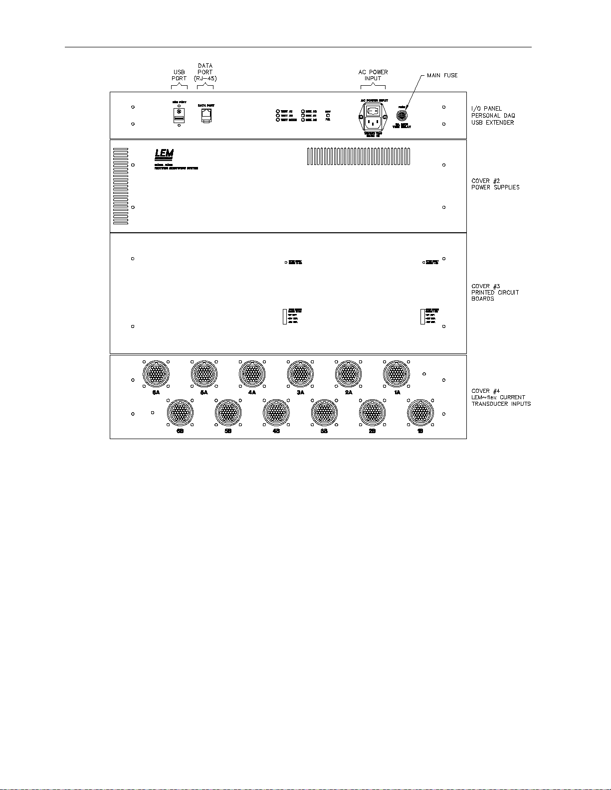
3.3 DATA ACQUISITION UNIT
The Data Acquisition Unit contains the following elements:
1.) Analog Card Rack containing:
© 2012 DynAmp, LLC Page 5
43756 G

Installation, Operation and Service Manual RCEM
2.) Backplane
3.) Reset Sync Cards
4.) Integrator Cards
5.) Personal Daq/56 – USB Data Acquisition Module
6.) USB Extender Receiver
7.) Digital Interface Module
3.4 LAPTOP COMPUTER
The laptop computer is connected to the Data Acquisition Unit via the USB Extender
Sender and RJ-45 cable. The laptop computer provides a means of displaying the rectifier
data. It also allows access to the internal test signal generator. The data is displayed on a
spreadsheet program.
3.5 FLEXIBLE CURRENT SENSORS
The 3.625 ID Flexible Current Sensor is the standard sensor supplied with the RCEM.
Other Flexible Current Sensor sizes are available from DynAmp, if required. Presently they
include inside diameter (I.D.) sizes of 1.000", 1.500", 2.750", 4.250", and 2.875” x 5.500”
models. All Flexible Current Sensors have the same output, so they may be interchanged.
3.6 MAGNETIC FIELD STATEMENT
The magnetic field from a high current DC bus may damage or destroy the laptop
computer hard disk drive, or floppy disks. To avoid damage the laptop and floppy disks
should be kept as far from the DC bus as practicable. Protect floppy disks in a
magnetic shielded case. This warning applies at all times.
The destructive effect of a magnetic field on a hard disk drive depends on the orientation of
the laptop computer within the field, and the degree of magnetic shielding provided by the
hard disk enclosure. Laptop computer and hard disk manufacturers do not provide
specifications for maximum magnetic field outside the hard disk enclosure.
It is difficult to accurately specify a maximum safe Gauss level for laptop computer disk
drives. Our best estimate is a maximum ambient magnetic field strength of 25 to 50 Gauss
for safe laptop computer operation.
This manual provides recommended guidelines for use of the rectifier monitoring system.
It is the sole responsibility of the customer to assure safety of equipment and personnel
when using this product.
© 2012 DynAmp, LLC Page 6
43756 G

Installation, Operation and Service Manual RCEM
Physical
Dimensions
Comments:
Data Acquisition Unit
22”W x 23”H x 13.75”D
(559 x 584 x 349) mm
Flexible Current Sensor
3.625 ID (92 mm)
Standard Size (other sizes are
available)
Sensor cable length
4.5 ft. (1.37 m)
Weight
Data Acquisition Unit
55 lbs. (20.5 kg)
Flexible Current Sensor
0.76 lbs. (0.28 kg)
3.625 ID Flexible Current
Sensor
Interconnection Cable
Length
33 ft (10 m)
Data Acquisition Unit(s) to
Flexible Current Sensor
USB Cable Length
15 ft (5 m)
Computer to USB Extender
Sender
Serial Data Cable Length
(Type Category 5E)
150 ft (45.7 m)
USB Extender Sender to Data
Acquisition Unit
USB Cable Length
15 ft (5 m)
Data Acquisition Unit #1 to
Channel Systems)
Environmental
Temperature
Comments:
Data Acquisition Unit
0°C to 50°C
Flexible Current Sensor
-20°C to +150°C
Humidity
Data Acquisition Unit
85% RH non-condensing
Flexible Current Sensor
85% RH non-condensing
4. SPECIFICATIONS
The specifications for the Rectifier Condition Evaluation Monitor are listed in Table 4.1.
TABLE 4.1
RECTIFIER CONDITION EVALUATION MONITOR SPECIFICATIONS
Data Acquisition Unit #2 (240
© 2012 DynAmp, LLC Page 7
43756 G

Installation, Operation and Service Manual RCEM
Electrical
AC Supply
Comments:
Voltage
90 – 135 Vac
175 – 264 Vac
Automatic Selection
Frequency
50/60 Hz
Basic Accuracy
3%
Flexible Current Sensors
Measuring Range
Flexible Current Sensor
0…2000A
Data Acquisition Unit
10 to 100%
Output
Analog Output
1V/1kA
Waveform Connectors
Serial Data
USB Port
Laptop Computer
Safety
Isolation
Comments:
Flexible Current Sensor
3000 VAC, 1 Minute @ 60 Hz
Data Acquisition Unit
Output to line
Installation Category III @ 300
Volts
Other
Visual Indicators
Comments:
Data Acquisition Unit
+24V LED
TEST A0 – TEST A1 LEDs
Personal Daq/56 Update Rate
4 seconds for 120 channels
TABLE 4.1
RECTIFIER CONDITION EVALUATION MONITOR SPECIFICATIONS (CONTINUED)
MUX A0 – MUX A2 LEDs
TEST MODE LED
© 2012 DynAmp, LLC Page 8
43756 G

Installation, Operation and Service Manual RCEM
DAU Data I/O Connector Variations
DAU Version
Data Port
USB Port
120 Channel
Installed
N/A
240 Channel DAU #1
Installed
USB “A”
240 Channel DAU #2
N/A
USB “B”
5. TECHNICAL DESCRIPTION
5.1 GENERAL
The Data Acquisition Unit (DAU) contains one analog card rack with backplane, reset sync
cards, and integrator cards. The Data Acquisition Unit also contains the Personal Daq/56
USB Data Acquisition Module, the USB Extender Receiver, and two power supplies. The
Personal Daq/56 accepts a maximum of 120 device data channels. The Data Acquisition
Unit #2 in a 240 Channel system does not contain an USB Extender Receiver.
5.2 BASIC THEORY OF OPERATION
Each current sensor is associated with the measurement channel for a specific rectifier
element. The signal from each current sensor is conducted to the DAU via an individual 2conductor cable and a wire pair within the interconnection cable.
The output from a current sensor is a voltage waveform corresponding to the
instantaneous change of current in the rectifier device associated with that current sensor.
Integrating the output signal of the current sensor returns it to the current waveform being
conducted by the rectifier device. The current waveform is converted to a DC voltage
proportional to the RMS value of the integrated signal.
The analog card rack contains multiplexer circuits to switch the DC voltage signals into the
twenty analog input channels located in the Personal Daq/56. The digital I/O in the
Personal Daq/56 controls the multiplexer. The multiplexing scheme can be described as a
6-leg by 20-channel matrix. One of six integrator channels ("legs") is addressed on all 20
integrator cards.
5.3 ANALOG CARD RACK
The analog card rack contains the following elements: one backplane, two reset sync
cards, and twenty integrator cards. See Figure 5.1.
© 2012 DynAmp, LLC Page 9
43756 G
Installation, Operation and Service Manual RCEM
5.4 BACKPLANE
The digital interface circuits to/from the Personal Daq/56 are located on the Data
Acquisition Unit backplane. The backplane also contains the reset sync cards connectors,
the integrator card connectors, the signal input connectors from the current sensors, and
the power circuits.
The backplane also contains the ac zero-crossing detector circuit. This circuit supplies the
ac zero-crossing timing pulse to the reset sync pulse generator and the test signal
generator circuits located on the Reset Sync Cards.
5.5 POWER CIRCUITS
The power circuits in the Data Acquisition Unit consist of the ac power input circuit, the
regulated quad output power supply, the +12V power supply, the + 5V power supply, and
the dc power input circuits.
Figure 5.1
Analog Card Rack
© 2012 DynAmp, LLC Page 10
43756 G
Loading...