

Page 1

Model 4000 and 4050
Stamping Press Controllers
Instruction Manual
Part Number IM-110005-8404
7900 Durand Avenue, Bldg 3 Sturtevant, WI USA 53177
Toll Free: 800-548-21 69 Ph one: 262-554-7977
Email: [email protected]
Website: dynamatic.com
Page | 1
Page 2

Please Observe the Following Safety Guidelines
Allow Installation and Service by Qualified Personnel Only: Electrical rotating equipment and
associated controls can be dangerous. Therefore, it is essential that only trained personnel be allowed
to work with this equipment, under competent supervision. The danger is when the equipment is not
handled, installed, maintained or used properly. This equipment must be installed, adjusted and
serviced only by qualified personnel familiar with the construction and operation of the equipment and
the hazards involved. Failure to observe this precaution could result in personal injury and/or equipment
damage.
Read Instruction and Warnings: These instructions should be read and clearly understood before
working on the equipment. Become especially familiar with all safety instructions and procedures. Read
and heed all danger, warning and caution notices contained in this manual and attached to the
equipment and be sure to instruct other is their meaning and importance.
Danger, High Voltage Disconnect Power Before Servicing Equipment: Various component parts and
terminals of the drive equipment are at or above line voltage when AC power is connected to the input
terminals. All ungrounded conductors of the AC power line must be disconnected before it is safe to
touch any internal parts of this equipment. Some control equipment may contain capacitors that retain
a hazardous electrical charge for a period after power is removed. After power is removed, wait at least
two minutes to allow capacitors to discharge before touching any internal parts of the equipment.
Failure to observe these precautions could result in fatal injury.
Precautions When Working on Live Circuits: Stand on an insulating mat. Make a habit of using only one
hand. Make sure that there is another person nearby in case emergency assistance is required.
Application of Equipment and Safety Devices: The adjustable speed drive and all components of the
drive system, such as operator control devices, electrical power distribution equipment, the motor and
mechanical power transmission equipment, must be properly selected and applies to assure a safe and
reliable installation. Each individual installation has unique requirements for safety equipment such as
emergency stop pushbuttons, pre-start alarms, motor and power disconnect devices and guards on
mechanical power transmission apparatus. The party responsible for the overall design and operation of
the facility must make sure that qualified personnel are employed to select and apply all components of
the drive system including appropriate safety devices.
Hazard of personal injury or equipment damage exists if the drive and/or the driven machine are
operated above their rated speed due to miss adjustment or electronic failure. Be sure to consider this
factor in selecting gear ratios and safety devices.
Page | 2
Page 3

Always Wear Safety Glasses: Safety glasses should be worn by all personnel involved in installing or
maintaining the equipment. This applies equally to all electrical and mechanical workers. Other safety
clothing should be selected as appropriate to the task and work environment.
Handle with Care: Handle the equipment carefully to avoid personal injury or damage to the unit.
Provide Appropriate Guards Around Moving Parts: Before operating the equipment, make sure that
appropriate guards and other safety devices are in place. Refer to OSHA rules and regulations,
paragraph 1910.219 for guards on mechanical power transmission apparatus.
Observe Requirements of the National Electric Code: All wiring must be in accordance with the National
Electrical Code (NEC) and/or other codes as required by the authority having jurisdiction. The electrical
connections completed by the installed must conform to the Instructions and diagrams supplied.
National Electric Code Article 430-102 requires a disconnecting means for each motor and controller
located in sight from the motor, controller and driven machinery locations or capable of being locked in
the open position if not located in sight. This disconnecting means is not included with the drive
equipment unless specifically ordered.
Not for Use in Hazardous Locations: Unless specifically labelled as approved for such use, this
equipment is not suitable for use in an explosive atmosphere or in a “Hazardous (Classified) Location” as
defined in article 500 of the National Electrical Code.
Provide Adequate Ground Connections: For personnel safety and reliable equipment operation, firmly
earth ground each piece of equipment as directed in this manual and shown on the connection diagrams
provided. The ground conductor should be the same size as the incoming power wires or sized according
to NEC table 250-95. A copper or aluminum conductor must be used. Grounded conduit connections are
not adequate for use as equipment ground connections.
Instruction Material and Drawings: In addition to this manual, data sheets, drawings, supplementary
instruction sheets may be included in the package of instruction material that is furnished for each drive.
Be sure to save each of these items for future reference. The drawings and data included in this manual
are generally representative of the product line, but do not accurately include every detail pertaining to
specific equipment provided for an individual customer order. Drawings and data sheets which are
identified by PRO/Serial number as pertaining to specific piece of equipment take precedence over this
manual. Note: The information furnished may not cover changes made to the equipment after
shipment. All data is subject to change without notice.
Technical Assistance: Please contact Dynamatic at 1-800-548-2169 or 262-554-7977
Page | 3
Page 4

Table of Contents
Section 1 ........................................................................................ 7
General Information .................................................................................................................... 7
Introduction ............................................................................................................................. 7
Safety ....................................................................................................................................... 7
Training .................................................................................................................................... 7
Receiving and Damage Claims ................................................................................................. 8
Warranty .................................................................................................................................. 8
Handling ................................................................................................................................... 8
Storage ..................................................................................................................................... 8
Long Term Storage ................................................................................................................... 8
Removal from Storage ............................................................................................................. 9
Section 2 ...................................................................................... 10
General Description ................................................................................................................... 10
Table 2-1 Specifications ..................................................................................................... 10
Basic Controller Assembly ...................................................................................................... 11
Table 2-2 Panel Mount 4050 Controllers with a Transformer ........................................... 12
Drive Description and Application ......................................................................................... 12
Model 4000-4050 Comparison .............................................................................................. 13
Installation ............................................................................................................................. 13
Operation ............................................................................................................................... 13
Start-up and Adjustments ...................................................................................................... 13
Figure 2-1 Stamping Press Controller 15-541-000* with torque Limit, Speed Trip, and
Minimum Adjustment Panel Outline Mounting Dimensions.......................................................... 14
Figure 2-2 Stamping Press Controller 15-541-002* with Torque Limit Minimum Speed
Adjustment (w/o Speed Trip) Panel Outline Mounting Dimensions
ure 2-3 Stamping Press Controller 15-539-0019 with Torque Limit and Minimum
Fig
Speed Adjustment Panel Outline Mounting Dimensions ............................................................... 16
Figure 2-4 Stamping Press Controller 15-539-0020 with Torque Limit and Minimum
Speed Adjustment Panel Outline Mounting Dimensions (Typical Layout/Subject to Change) ...... 17
.............................................. 15
Section 3 ...................................................................................... 18
Installation ................................................................................................................................. 18
Mounting Panel Mounted Controllers ................................................................................... 18
Mounting an Input Transformer ............................................................................................ 18
Figure 3-1 Input Transformer ............................................................................................. 18
Main Printed Circuit Board Support ....................................................................................... 19
Page | 4
Page 5

Modification PCB ................................................................................................................... 19
Figure 3-2 Modification PCB Standoff ................................................................................ 19
Wiring ..................................................................................................................................... 20
Programming Dip Switch ....................................................................................................... 21
Figure 3-3 Dip Switch Installation & Programming ............................................................ 21
Figure 3-4a Connection Diagram Model 4050 Stamping Press Controller with Torque
Limit, Speed Trip and Minimum Speed Adjustment 115V, 208V, 390V, 230/460V or 575V Input
and 8.0 Adc Output (15-541-*) ....................................................................................................... 22
Figure 3-4b Schematic Diagram for Model 4050 Stamping Press Controller (15-541-*)
continued… ..................................................................................................................................... 23
Figure 3-5a Connection Diagram for 4050 Stamping Press Controller with Torque Limit.
Speed Trip and Minimum Speed Adjustment 208/230/460V Input and 5.5 Adc Output (15-541-
0007) ............................................................................................................................................... 24
Figure 3-5b Schematic Diagram for 4050 Stamping Press Controller with Torque Limit
continue .......................................................................................................................................... 25
Figure 3-6a Connection Diagram for 4050 Stamping Press Controller with Torque Limit
and Minimum Speed Adjustment (without Speed Trip) 115V, 208V, 390V, 230/460V or 575V
Input and 8.0 Adc Output (15-451-002*)........................................................................................ 26
Figure 3-6b Schematic Diagram for 4050 Stamping Press Controller (15-451-002*)
continued… ..................................................................................................................................... 27
Figure 3-7a Connection Diagram for Model 4050 Stamping Press Controller with Torque
and Minimum Speed Adjustment 115V input and 8 Adc. Output (15-539-0019) .......................... 28
Figure 3-7b Schematic Diagram for Model 4050 Stamping Press Controller (15-539-0019)
continued… ..................................................................................................................................... 29
Figure 3-8a Connection Diagram for Model 4050 Stamping Press Controller with
minimum Speed Adjustment (without Torque Limit) 115 V input and 8 Adv output (15-539-0020)
........................................................................................................................................................ 30
Figure 3-8b Schematic Diagram for Model 4050 Stamping Press Controller (15-539-0020)
continued ........................................................................................................................................ 31
Section 4 ...................................................................................... 32
Operation ................................................................................................................................... 32
Basic Controller Theory .......................................................................................................... 32
Figure 4-1 Simple Closed Loop System .............................................................................. 32
rque Limit Modification 15-44-2 ........................................................................................ 33
To
Linear Acceleration Option .................................................................................................... 33
Fixed Brake Option ................................................................................................................. 34
Spring Set Brake Option ......................................................................................................... 34
Speed Trip Option .................................................................................................................. 34
Figure 4-2 Model 4050 Controller Block Diagram ............................................................. 35
Page | 5
Page 6

Section 5 ...................................................................................... 36
Start-Up and Adjustments ......................................................................................................... 36
Tools Required ....................................................................................................................... 36
Power Off Test ....................................................................................................................... 36
Power On Test ........................................................................................................................ 37
Set-Up Main PCB Assembly .................................................................................................... 38
Preliminary Adjustments ....................................................................................................... 38
Figure 5-1 Trimpot Illustration ........................................................................................... 39
Basic Speed Control (without Torque Limit) .......................................................................... 40
LED Set-Up ............................................................................................................................. 40
Max Speed/Volts R21, Alternate Methods .................................................................... 41
Control with Torque Limit Modification ................................................................................ 43
Section 6 ...................................................................................... 45
Maintenance and Troubleshooting ........................................................................................... 45
Maintenance .......................................................................................................................... 45
Troubleshooting ..................................................................................................................... 46
Renewal Parts and Service ..................................................................................................... 47
Renewal Parts List .............................................................................................................. 48
Loose Parts for 4050 Stamping Press Controller ............................................................... 51
Page | 6
Page 7

Section 1
General Information
Introduction
This instruction manual contains the necessary information required for normal installation, operation
and maintenance of the Model 4050 Stamping Press Controllers. Please make it available to all
maintenance and operating personnel.
Instructions provided in this manual are arranged in their normal order of use. Beginning with general
information, the instructions proceed from receiving, handling and storage, through installation, startup and adjustments to maintenance and trouble shooting. Written as a guide, these instructions do not
cover or describe each detail or modification in the controller. Use this instruction manual in conjunction
with any specific schematic, prints or instructions supplied with your controller. Certified drawings shall
take precedence over printed instruction material if a difference in content occurs.
While every effort has been made to provide a complete and accurate manual, there is no substitute for
trained, qualified personnel to handle unusual situations. If any questions arise regarding the operation
or maintenance of this controller, please refer them immediately to Dynamatic Customer Service at
1-800-548-2169 or 262-554-7977.
Safety
With any electronic or electrical rotating equipment, potential safety hazards are present and require
safeguards for proper use. This equipment must be installed properly, using safe procedures that meet
the requirements of all applicable safety codes. The wiring must be in accordance with the National
Electrical Code and all other local codes and regulations. Shaft guards, as well as protection for
operating and maintenance personnel against high voltage and moving machine parts, is essential. Refer
to OSHA rules and regulations, paragraph 1910.219, for guards on mechanical power transmission
apparatus. Pleases heed these safety instructions.
DANGER, WARNING, CAUTION and special INSTRUCTION labels are applied to the equipment to remind
you of the hazards the exist. Know your equipment before handling or working on it.
DANGER… is used where an immediate hazard exists. Failure to follow instructions could be fatal
WARING… means a possibility of injury to personnel, but not as severe as a Danger Warning.
CAUTION… is used to warn of potential hazards and unsafe practices.
INSTRUCTION… labels and notes are used when there is a need for special instructions related to safety,
proper operation or maintenance.
Training
Training programs are an essential part of safe and correct operation. Training provides the know-how
necessary to obtain top performance from your equipment. Dynamatic recognizes this fact and conducts
training schools to educate your plant personnel in safe maintenance and operating procedures. There is
a nominal charge for this service. Contact customer service at 262-554-7977 to set up a date.
Page | 7
Page 8

Receiving and Damage Claims
The Model 4050 Stamping Press controller have been operated and tested at the factory prior to
shipment. Specific test procedures are followed to assure the quality of your controller. Carrier
approved packing methods assure safe shipment to your plant. Shipment is made F.O.B. from our
factory, with the carrier assuming responsibility for your unit. Therefore, it is essential that you carefully
inspect the shipment upon delivery to ensure that no damage or lost items have occurred in transit, Loss
or damage is covered by the carrier, not by the product warranty. File a claim immediately with the
carrier if any damage or loss is found. Should you require assistance in settling your claim with the
carrier, contact Dynamatic. You will need the unit model number, serial number and your purchase
order number for identification.
Warranty
Your new Model 4050 Stamping Press controller is covered by a one-year warranty against any
manufacturing defect in either material or workmanship. Should the controller fail with in the one-year
warranty period, contact Dynamatic for a repair Return Material Authorization (RMA) form. Fill in all
required information on the form and return the form with the controller to our Repair Service
Department in Sturtevant, Wisconsin for warranty repair or exchange. Your controller will either be
repaired or replaced with a preciously repaired exchange controller. Freight charges both ways are your
responsibility.
Handling
Then Model 4050 Stamping Press controllers weigh only a few pounds and can be hand carried safely.
Do not drop or subject the controller to shock or vibration. Do not stack heavy material on the
controller. The printed circuit boards and other components may be mounted on an open panel making
the controller very accessible to damage
Storage
Store the controller in a clean dry location with a non-corrosive atmosphere protected from sudden
temperature changes, high levels of moisture, shock and vibration. Electrical components are delicate
and easily damaged; provide adequate protection for them.
Ambient temperature should not exceed 40°C (104°F). The minimum temperature must remain above
freezing and the dew point of ambient air. High temperature, corrosive atmosphere and moisture are
detrimental to controller equipment.
Long Term Storage
The manufacturer’s warranty covers repair or replacement of defective materials and rectification of
faulty workmanship. It does not cover damage and deterioration that transpire during the storage
period.
Some examples of deterioration due to storage are:
1. Corrosion of terminals and contacts
2. Breakdown of electrolytic capacitors
3. Moisture absorption within insulation and composition resistors.
Page | 8
Page 9

These are not manufacturer’s defects and will not be covered by the warranty policy. Refer questions to
the Field Service Department in Sturtevant Wisconsin.
Removal from Storage
Before returning the controller to service after long time storage, it will be necessary to carefully inspect
it for any signs of damage or deterioration. Correct any deficiency. Carefully inspect the controller for
signs of moisture, especially with respect to transformers and composition resistors. If moist, the
transformer will require thorough drying. Damp resistors will change impedance and affect performance
of the controller; they should be replaced.
Corrosion is an important factor. Inspect terminals, plugs, sockets and contacts for signs of corrosion. If
detected, cleaning will be necessary.
Before applying power, make sure all connections are tight.
These procedures are given only as recommendations offered to aid our customers in preserving stored
equipment. We cannot guarantee stored equipment, even if all suggestions are followed; damage or
deterioration may still occur. Equipment storage is not covered by warranty.
Page | 9
Page 10

Section 2
Input Voltage
115 Vac, CT. +20%, -10%, 50/60 Hz
Input Current
7Aac rms
Output Voltage
45 Vdc nominal at either terminals C1 or C2
(clutch) or B1 and B2 (brake)
Output Current
8 Adc continuous
Extra Run Relay Contact (NO)
115 Vac, or 24 Vdc, 5A resistive, 150 V. pilot duty
Load Regulation
-0.5% of maximum rated speed for no load to
100% load change
Line Regulation
±0.1% of rated speed for ±10% input line voltage
change
Thermal Drift
±0.05% of rated speed per degree C. (or ±0.03%
per degree F.)
Linearity
±2% of maximum rate speed, reference voltage
to speed
Min Regulated Speed
50 rpm
Zero Adjust Range
0 to 15% of rated speed
Linear Accel Range
3 to 80 seconds
Fuses FU1, FU2
10 A, 250 Vac
Ambient
0°- 40°C. (32°- 104°F.) Cast enclosure Model 4000
0°- 65° (32° - 148° F.) Panel mount Model 4050
Mounting
NEMA 13 or open panel
General Description
The Model 4050 stamping press controllers are solid state eddy current controllers employing an
integrated circuit design with a transistorized output. The controller is designed to provide a current
output of 8 amps at 45 volts, so it can be used on Ajusto-Spede drives from 1 through 125 hp. See table
2-1 for a full list of specifications. Descriptions of other features available on these controllers follow.
Table 2-1 Specifications
The adjustable time constant circuit matches the controller to the time constant of the mechanical unit.
An LED Set-Up Indicator Circuit enables the maximum speed and minimum bias to be set visually be
means of an “onboard” light emitting diode, in most cases eliminating the need for a meter. Because the
requirements for damping increase with higher horsepower drives and higher inertia, the velocity
damping ranges on the Model 4050 stamping press controllers have been extended to approximately
twice that of the original Model 4000 controller. Current feedback damping is available for customers
who require this type of response. The output of each controller is short circuit proof, which includes
the following conditions:
1. Shorting of terminal C1 to C2
Page | 10
only
Page 11

2. Shorting of terminal B1 to B2
3. Shorting of terminals C1 or C2 to earth ground
4. Shorting of terminals B1 or B2 to earth ground
If any of these events occur, the controller shall be completely self-protecting without damage to any of
its internal components. Input power for the controller can be supplied from either a 115 Vac
transformer winding mounted in the controller or in the drive’s ac motor. A separately mounted 115 Vac
transformer is also available if required. Pushbutton operation by Run relay is standard; also, the Run
relay has an extra set of NO (normally open) contacts available for customer’s use.
Various features have been added to prevent possible damage and improve the reliability of the Model
4050 controller. Additional circuitry has also been added to improve performance and simplify set up.
These features include primarily the output circuit short circuit protection, transient overvoltage
protection and higher rated power devices. An addition of a buffer amplifier circuit will shut off the
controller output with a loss of reference input signal. LED circuitry allows for minimum and maximum
speed adjustment to be made easily without instrumentation feedback. Also, the current circuit
improves drive response under special low inverter, light load applications.
The Model 4050 stamping press controllers are designed for customer mounting within existing
enclosures. These are two basic configurations of the panel mounted controller. One version includes an
optional transformer and the other does not.
All versions of the Model 4050 stamping press controller include a Minimum Speed potentiometer
controls the range that the external Run Speed potentiometer will have to adjust the speed of the drive.
It can be adjusted to prevent the Run Speed potentiometer from setting the drive speed below a
minimum safe flywheel operating speed.
The Torque Limit feature is used to accelerate the flywheel at the fastest rate possible without
excessively overloading the motor. The Ajusto-Speede drive has an overload capability of approximately
200% of rated motor capacity. If the flywheel was accelerated using the full overload capacity of the
drive, it could shorten the life of the motor or permanently damage it. The torque Limit circuit overrides
the speed reference (100% to 150% of rated motor torque). The drive continues to deliver torque and
accelerate the flywheel, but at a controlled value that will not damage the motor or trip the motor
starter overloads.
The Trip Circuit functions at one fixed speed by utilizing on input signal and setting the desired trip point
with the Trip Speed potentiometer R1. The input signal is usually obtained from a generator
(tachometer) which indicated speed. The output of the trip circuit is a set of dpdt relay contacts which
switch when the trip point is reached for customer use.
Basic Controller Assembly
Basic Model 4050 stamping press controllers are available with or without a transformer. The panel
transformer model has an optional trip circuit available in addition to various input voltages.
See table 2-2.
Page | 11
Page 12
Mounting of the 15.12” x 11.38” transformer mount panel is by means of the four corner holes
Panel Number with Torque
Panel Number with Torque
Input Voltage, Frequency
15-541-0001
15-541-0021
115 V, 50/60 Hz.
15-541-0002
15-541-0022
208 V, 50/60 Hz.
15-541-0003
15-541-0023
390 V, 50/60 Hz.
15-541-0004
15-541-0024
230/460 V, 60 Hz.
15-541-0005
15-541-0025
575 V, 60 Hz.
15-541-0007*
--
208/230/460 V, 50/60 Hz
provided. See Figures 2-1 and 2-2 for mounting dimensions and depth requirements. Requirements.
Components included on each panel are as follows: main PCB1, 15-530-6; modification PCB2, 15-444-2;
T1 transformer; and the TB1 terminal board. The trip circuit assembly is included only on those
assemblies covered by Figure 2-1.
Table 2-2 Panel Mount 4050 Controllers with a Transformer
Limit and Trip Circuit
*Special reduced output controllers: 5.5 Adc output current.
The panel mount version without a transformer is available with or without the Torque Limit
modification. Both versions include Minimum Speed adjustments. The 10.25” x 6.00” panel is mounted
by the three holes provided. See Figures 2-3 and 2-4 for outline drawings and mounting dimensions.
Components included on each panel are as follows: main PCB, 15-530-6. TB1 terminal board; and the
Minimum Speed potentiometer. The 15-444-2 Torque Limit modification PCB is included on the 15-53919 assembly (Figure 2-3)
The main PCB (15-530-6) is mounted to the panel with four standoffs. A ground stud is provided for
grounding the panel. A13 position terminal block across on end of the main PCB assembly is provided to
make connections to it. Near the center, along on side of the board, is a 16 pin receptacle (RECP1) into
which is plugged a 4 pole, 8 pin Dip Switch (SW1). When modification PCB 15-444-2 is used, this Dip
switch is removed and replaced with a 16 pin plug and mod interconnect ribbon cable.
Limit (less Trip Circuit)
Modification printed circuit boards (15-444-2) is mounted to the main PCB with four nylon standoffs.
These standoffs serve as licking devices to hold the two PCBs together securely. See Figure 2-1, 2-2 and
2-3. This modification printed circuit board measures 3.50” x 3.90”. It is connected electrically to the
main PCB assembly with a 16 pin ribbon connector and a separate push-on jumper that connects
terminal C2 of the mod PCB to terminal FC2 of the main PCB assembly. A separate current transformer is
furnished for mounting in the junction box of the mechanical unit, or as a loose item for mounting by
the customer.
Drive Description and Application
The Ajusto-Spede drive is a combination of an air cooled, eddy current clutch and an integrally mounted,
design 88, ac induction motor. The Ajusto-Spede drive transmits constant torque at variable speeds.
With the eddy-current principle of torque transmission, these is no physical contact between input and
Page | 12
Page 13

output members. This results in smooth response, eliminating shock loading and extending the life of
Item Specifications
4000
4050
Drive Range
1 to 20 Hp
1 to 125 Hp
Main PCB Assy
15-530-5
15-530-6
Input Current
4 Aac rms
7 Aac rms
Output Current
4.3 Adc continuous
8 Adc continuous
Fuses FU1, FU2
4 A, 250 Vac
10 A, 250 Vac
the equipment.
The Ajusto-Spede drive restores the energy extracted by the flywheel going through the work portion of
the stroke. In this application, it is the flywheel that delivers the energy to the press for the work, not
the Ajusto-Spede drive. Because of this, it is the flywheel capacity that determines the minimum
operable press speed.
The 4050 stamping press controller is designed to meet the requirements of stamping press applications
by providing these two basic functions:
1. To accelerate the flywheel to an adjustable running speed within the speed range of the press.
2. To provide minimum and maximum limits of Run Speed adjustments to avoid improper
operation of the press.
When the Torque Limit modification is furnished, the drive torque is limited by the setting of the Torque
Limit potentiometer. This feature is used to avoid excessive overload of the motor when accelerating a
high inertia flywheel, or when the press load causes a significant change in the flywheel, or when the
press load causes a significant change in the flywheel speed.
When the Speed Trip circuit is furnished with the press drive controller, it is employed as a speed trip
that will energize above zero speed. The setting of the Trip speed potentiometer determines the Speed
Trip setting.
Model 4000-4050 Comparison
The assemblies 15/533-1019 (Model 4000) and 15-539-0019 (Model 4050) panel mount controllers are
very similar in appearance. The primary difference is the 4050 heatsink, HR1, with the power
semiconductors. On the Model 4000 these semiconductors (D1, D2, and Q1) are mounted on the main
PCB assembly so the off-board heatsink is not required.
Installation Follow the installation instructions in section 3 of this manual, except that the input
wiring is only required to carry at 4amps at 115 Vac. The dc output to the coils is 45 Vdc at 4.3 amps. All
other controller wiring is 5 amps or less
Operation of the model 4000 controller is similar to the Model 4050 controller as described in
the manual. However, the Model 4000 controller is not available with the Speed Trip option
Start-up and Adjustments for Model 4000 stamping press controllers, follow the applicable
Model 4050 Start-Up and Adjustment procedure in the manual
Page | 13
Page 14
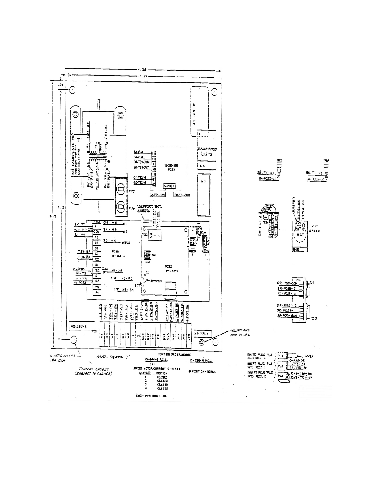
Figure 2-1 Stamping Press Controller 15-541-000* with torque Limit, Speed Trip, and Minimum
Adjustment Panel Outline Mounting Dimensions
Page | 14
Page 15
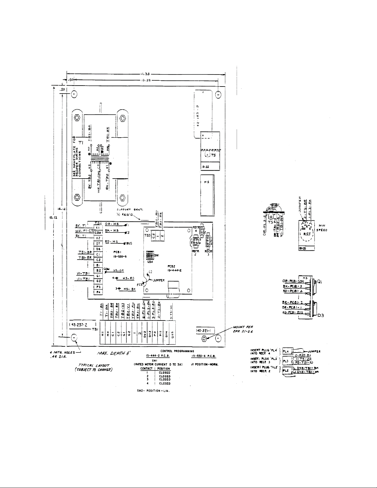
Figure 2-2 Stamping Press Controller 15-541-002* with Torque Limit Minimum Speed Adjustment
(w/o Speed Trip) Panel Outline Mounting Dimensions
Page | 15
Page 16
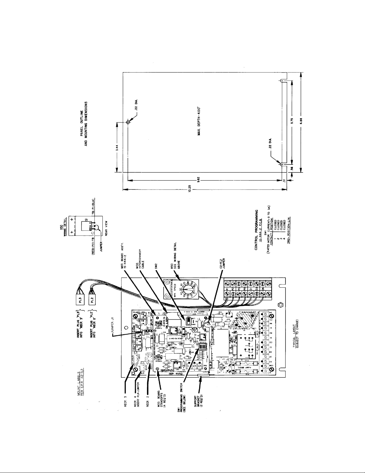
Figure 2-3 Stamping Press Controller 15-539-0019 with Torque Limit and Minimum Speed
Adjustment Panel Outline Mounting Dimensions
Page | 16
Page 17
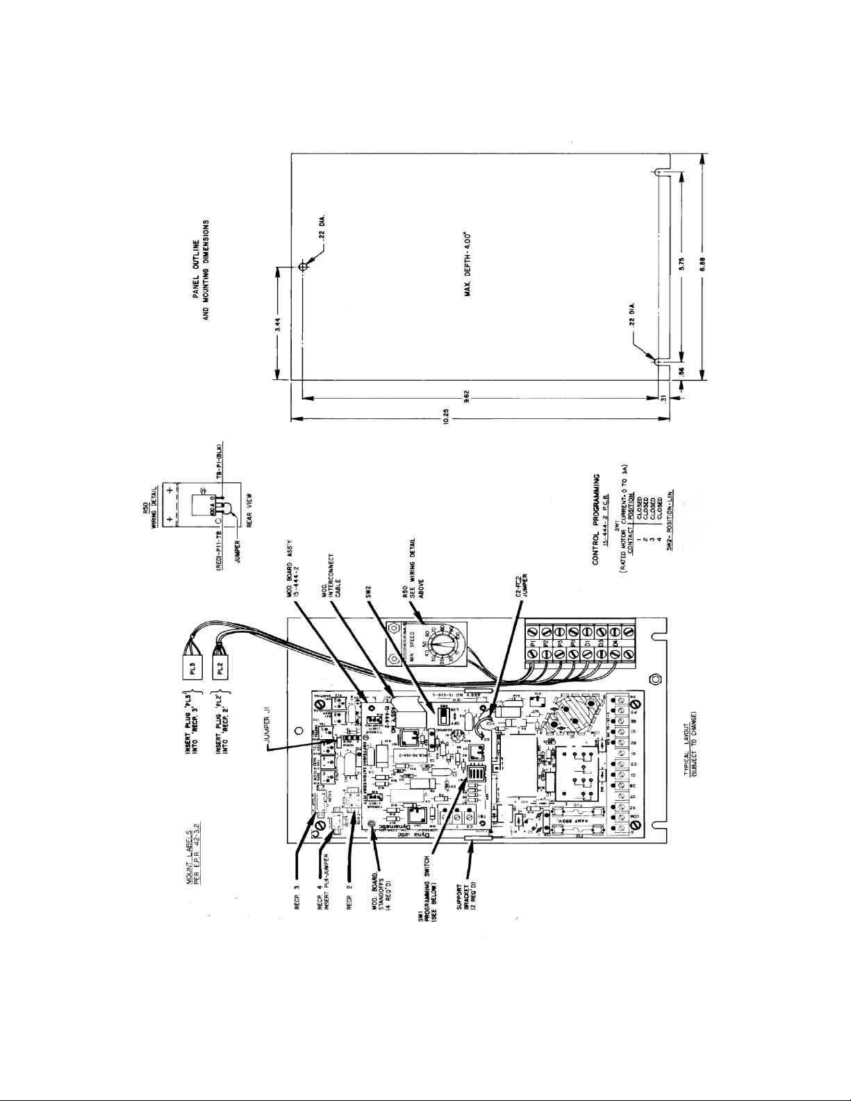
Figure 2-4 Stamping Press Controller 15-539-0020 with Torque Limit and Minimum Speed
Adjustment Panel Outline Mounting Dimensions (Typical Layout/Subject to Change)
Page | 17
Page 18
Section 3
Installation
Mounting Panel Mounted Controllers
The Model 4050 panel mount stamping press controllers should be mounted with the main PCB/panel
terminal block toward the bottom of your enclosure. The minimum depth required for the controller is
wither 4” or 8” (refer to the panel outline mounting dimension drawings in figures 2-1 through 2-4 for
your specific models) You may use the controller as a template or use the appropriate outline mounting
drawing to locate the required mounting holes. The panels with a transformer that are shown in Figures
2-1 and 2-2 should be mounted with 3/8” hardware in each of the four corner holes. Panels without a
transformer should be mounted with No. 10 hardware, such as 10-24 or 10-32, in the three positions
shown.
Mounting an Input Transformer
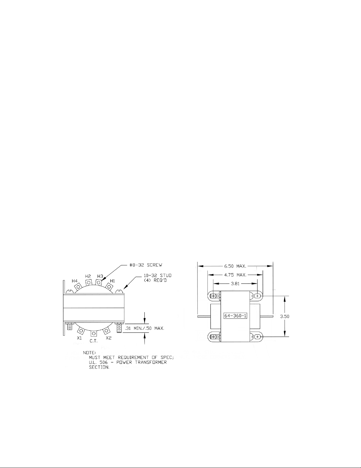
If a loose transformer is furnished, a suitable location should be selected for installing it. Figure 3-1
includes mounting dimensions. Orient the transformer for ready access to primary and secondary
terminals, which are clearly marked. Using adequate size hardware, secure the transformer in place.
Check transformer input and output requirements. Before wiring it to the input supply and to the
controller.
Figure 3-1 Input Transformer
Page | 18
Page 19

Main Printed Circuit Board Support
If it is necessary to install the main PCB 15-530-6 onto the panel, the following instructions are provided
to help you with this task. Position the board so that it is supported by each of the two support brackets.
Then mount the printed circuit board to the panel with the four mounting screws that are furnished.
Modification PCB
The Torque Limit modification PCB 15-444-2 schematic is included in Figure 3-11. If its is necessary to
install this modification PCB onto the main PCB, 15-530-6, the following instructions are provided to
help you with this task:
1. Place the main PCB in front of you with the long dimension in a horizontal position and the
terminal strip to the left
2. Locate the dual in-line, 4 position Dip switch plugged into receptacle RECP 1 on the main PCB
assembly. With the main PCB terminal block to the left, RECP1 is 2.5” from the right edge and
1.0” from the bottom, edge of the board.
3. Remove the Dip switch by pulling it straight out of the receptacle. Save the switch for some
future use. Then, peel the adhesive-backed label off the other half of RECP 1.
4. Four nylon standoffs are supplied with each modification PCB assembly. Locate the four 0.188”
diameter holes in the main PCB assembly. Insert the arrow type locking head of a standoff into
each of the holes in the main PCB assembly and press them in (see Figure 3-2) The Tabs will snap
out to lock the stand-offs permanently in position. Replacement standoffs are available by
ordering the standoff kit assembly 15-263-16, which contains four standoffs.
Figure 3-2 Modification PCB Standoff
Page | 19
5. Hold the modification PCB
assembly over the standoffs with the
ribbon connector toward you, which
should be over the RECP 1 Receptacle.
Insert the ribbon connector plug into
RECP 1. Be careful to see that all 16
pins are started properly into the
receptacle before pressing the plug in.
These pins are easily bent. To remove
this connector, pull straight up on the
body of the plug. Do not pull on the
ribbon itself.
Page 20

6. Align the holes in the modification PCB assembly over the standoffs and press ober the tapered
posts until the locking flanges snap out to lock the board in position. TO remove the board,
squeeze the locking flanges in with your fingers and lift off the board.
Wiring
The connection diagrams and schematics for all of the 4050 stamping press controllers are included in
Figures 3-4 through 3-8. The connection diagrams are in simplified block form. The large rectangular box
in the center of the diagram represents the controller panel, with the terminal strips shown, numbered
and lettered exactly as they appear on the actual controller panel. The rotating unit’s electrical devices
that must be wired are shown on the left side of the connection diagram. Connections between the
drive and controller are shown by the solid lines that are drawn between the appropriate terminal
points. The heavy solid lines represent a raceway or conduit run.
Starting at the top of the connection diagram, note the dotted box, labeled “Recommended disconnect
switch and motor starter circuit”. This dotted line indicates that these items are not included in the
Model 4050 stamping press controller packages. Since the drive uses a standard ac induction motor, it
must be connected with the proper branch circuit protection, motor starter and overload devices. The
minimum requirements are specified in the National Electrical Code; other local regulations may also
apply. If a question exists, consult Dynamatic 800-548-2169.
Wire size, number of conductors in a conduit or raceway and grounding are also specified by the
National Electrical Code and other applicable local regulations. Make sure that you meet minimum
requirements of theses codes. Consult the nameplate of the drive for full load current at the voltage you
are using. Controller input wiring should be sized to carry 115 Vac at 7 amps. The dc output to the coils
is 45 Vdc at 8 amps. All other controller wiring is 5 amps. All other controller wiring is 5 amps or less. In
most cases, the minimum conductor size allowed by code will be adequate. To avoid stray signal
interference, do not run the reference signal interconnection wires in the same conduit as the power
wiring.
Note that it is necessary to use shielded conductors for the generator leads, both for runs to the
controller and to any tachometer indicator that may be used. The shielded conductor should be a
twisted, insulated pair of conductors having a continuous metallic shield around the twisted pair with an
insulating jacket over the shield. At the generator and indicator ends, cut back the shield as required to
expose enough lead to make the connections. Then, tape the exposed shield so that it does not ground
at that point. On the controller panel, strip off enough of the outer jacket to expose several inches of
shield. Unwrap or unbraid the shield to obtain a bundle of separate strands. Twist the strands to form a
conductor and attach it to the ground. Make sure the shield ground connection cannot make contact
with the terminals at the terminal strip. Shielded cable should have the shield grounded at one end only.
When shielded cable is used, the generator leads may be run in the same conduit as the other
conductors. You may prefer to not use shielded cable; and if so, you must run the generator leads in
separate conduit with no other conductors. Keep wire length as short as possible.
After pulling the proper size conductors, connect each terminal at the drive to a controller terminal
having the same number or letters. As an example, C1 at the drive unit should be connected to terminal
Page | 20
Page 21
C1 at the controller. A screwdriver with a blade width not exceeding 1/8” should be used to loosen each
terminal screw. When the terminal screw is tight, back it out four (4) full turns. Route the conductor
neatly to the terminal, mark the length at a point that just reaches the back-insulating barrier, cut off
and then strip it to expose 5/16”. Insert the exposed conductor under the clamp below the screw head
and tighten. After tightening, check to make sure that no strands(s) of wire are curled back to short out
the conductor.
When all wiring is completed, recheck all connections again to make sure that they are correct, that
each is tight and that no exposed strands can short out at any point. Once you are sure that the wiring is
exactly as shown on the connection diagram, you may proceed to the next step, programming the
controller.
Programming Dip Switch
The basic controller contains one switch; when used with the Torque Limit modification, two switches
(SW1 and SW2) must be placed in the proper switch positions for the type of control action required.
Each connection diagram contains a table with the switch positions. Compare this drawing with your
unit to check the contact positions.
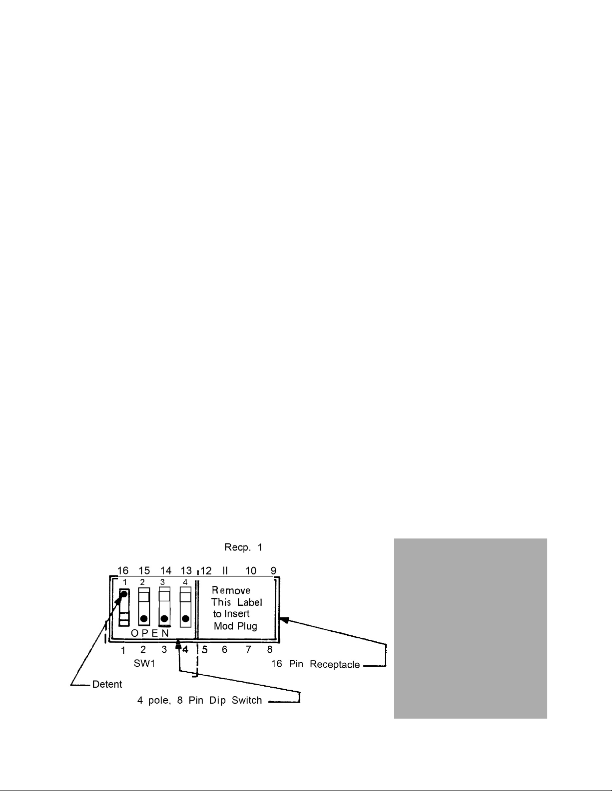
The main PCB assembly uses a Dip switch (SW1) except when the 15-444-2 modification PCB assembly is
used (this modification PCB has its own switch, as shown in figure 3-3). When looking at the board, with
the terminal block to the left, you will see a 4 pole, 8 pin switch plugged into the left half of the
receptacle (RECP1). The switch must be in this position. The switch poles have a rocker action. Contact 1
is on the left. If the controller programming chart on the connection diagram calls for contact 1 to be in
the COLSED position, place a pencil point in the switch rocker detent on the side opposite OPEN and
then press down to a position flush with the top of SW1. The OPEN side of contact 1 is now up. Refer to
the controller programming chart on the connection diagram for your controller and program each
contact of each switch per the chart.
Figure 3-3 Dip Switch Installation & Programming
Page | 21
Page 22
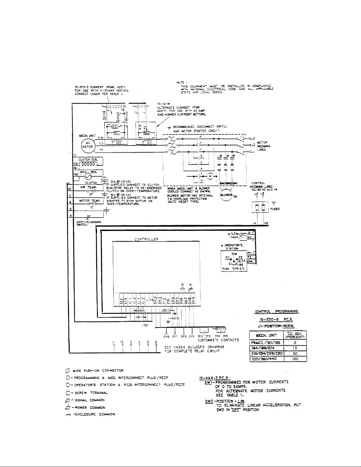
Figure 3-4a Connection Diagram Model 4050 Stamping Press Controller with Torque Limit, Speed
Trip and Minimum Speed Adjustment 115V, 208V, 390V, 230/460V or 575V Input and 8.0 Adc Output (15541-*)
53831
Page | 22
Page 23
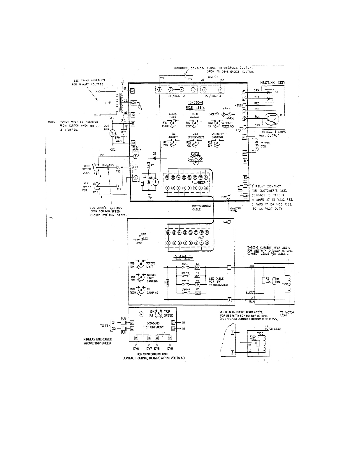
Figure 3-4b Schematic Diagram for Model 4050 Stamping Press Controller (15-541-*) continued…
53831
Model 4050 Stamping Press Controller with Torque Limit, Speed Trip and Minimum Speed Adjustment
115V, 208V, 390V, 230/460V or 575V Input and 8.0 Adc Output (15-541-*)
*15-541-0001, 15-541-0002, 15-541-0003, 15-541-0004, 15-541-0005
Page | 23
Page 24

Figure 3-5a Connection Diagram for 4050 Stamping Press Controller with Torque Limit. Speed Trip and Minimum Speed Adjustment 208/230/460V Input and 5.5 Adc Output (15-541-0007)
56832
Page | 24
Page 25
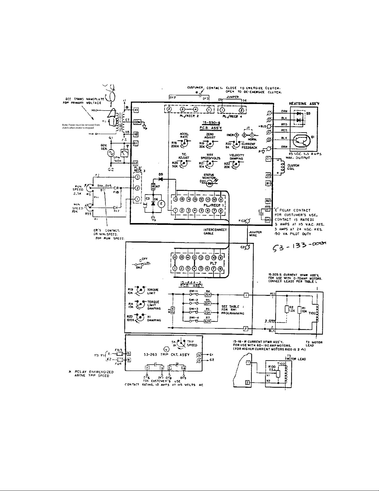
Figure 3-5b Schematic Diagram for 4050 Stamping Press Controller with Torque Limit continue
56832
4050 Stamping Press Controller with Torque Limit. Speed Trip and Minimum Speed Adjustment
208/230/460V Input and 5.5 Adc Output (15-541-0007)
Page | 25
Page 26
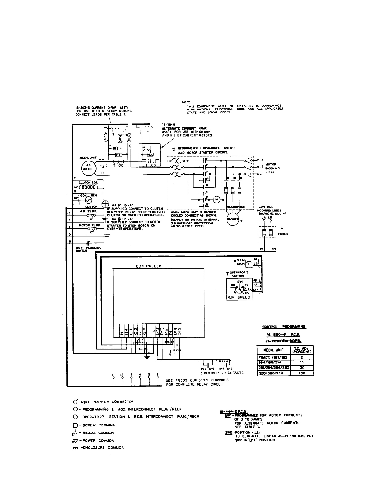
Figure 3-6a Connection Diagram for 4050 Stamping Press Controller with Torque Limit and Minimum Speed Adjustment (without Speed Trip) 115V, 208V, 390V, 230/460V or 575V Input and 8.0 Adc Output (15-451-002*)
56836
Page | 26
Page 27
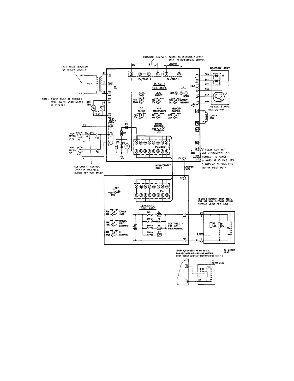
53836
Figure 3-6b Schematic Diagram for 4050 Stamping Press Controller (15-451-002*) continued…
Model 4050 Stamping Press Controller with Torque Limit and Minimum Speed Adjustment (without
Speed Trip) 115V, 208V, 390V, 230/460V or 575V Input and 8.0 Adc Output (15-451-002*)
*15-541-0021, 15-541-0022, 15-541-0023, 15-541-0024, 15-541-0025
Page | 27
Page 28
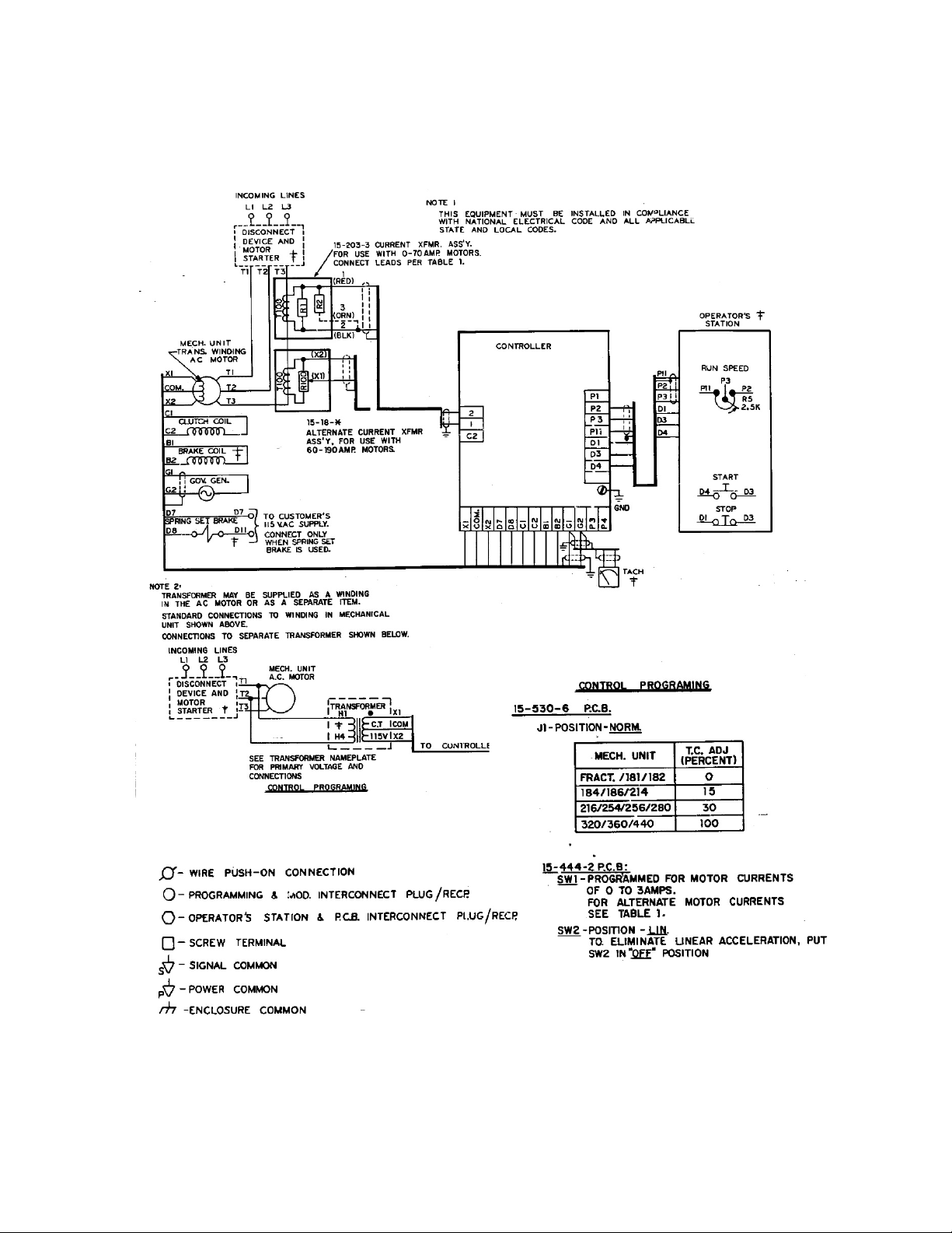
Figure 3-7a Connection Diagram for Model 4050 Stamping Press Controller with Torque and Minimum Speed Adjustment 115V input and 8 Adc. Output (15-539-0019)
56819
Page | 28
Page 29
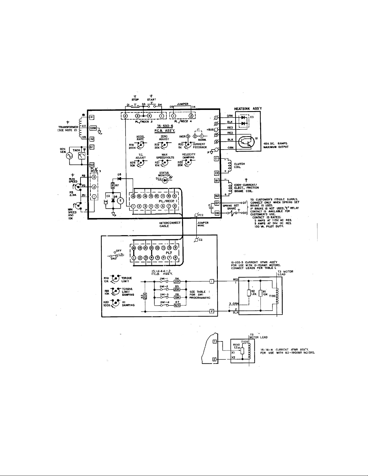
Figure 3-7b Schematic Diagram for Model 4050 Stamping Press Controller (15-539-0019) continued…
(Model 4000 is the same except 15-530-5 PCB Assembly is used. PCB assembly includes items shown
here as 15-529-19 heatsink assembly)
56819
Model 4000 Stamping Press Controller with Torque Limit and Minimum Speed Adjustment 115V input
and 4.3 Adc output (15-533-1019)
Model 4050 Stamping Press Controller with Torque and Minimum Speed Adjustment 115V input and 8
Adc. Output (15-539-0019)
Page | 29
Page 30
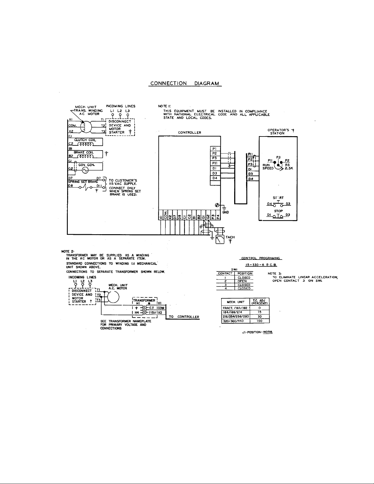
Figure 3-8a Connection Diagram for Model 4050 Stamping Press Controller with minimum Speed Adjustment (without Torque Limit) 115 V input and 8 Adv output (15-539-0020)
56820
Model 4000 Stamping Press Controller with minimum Speed Adjustment (without Torque Limit) 115 V
input and 4.3 Adc output (15-533-1020)
Model 4050 Stamping Press Controller with minimum Speed Adjustment (without Torque Limit) 115 V
input and 8 Adv output (15-539-0020)
Page | 30
Page 31
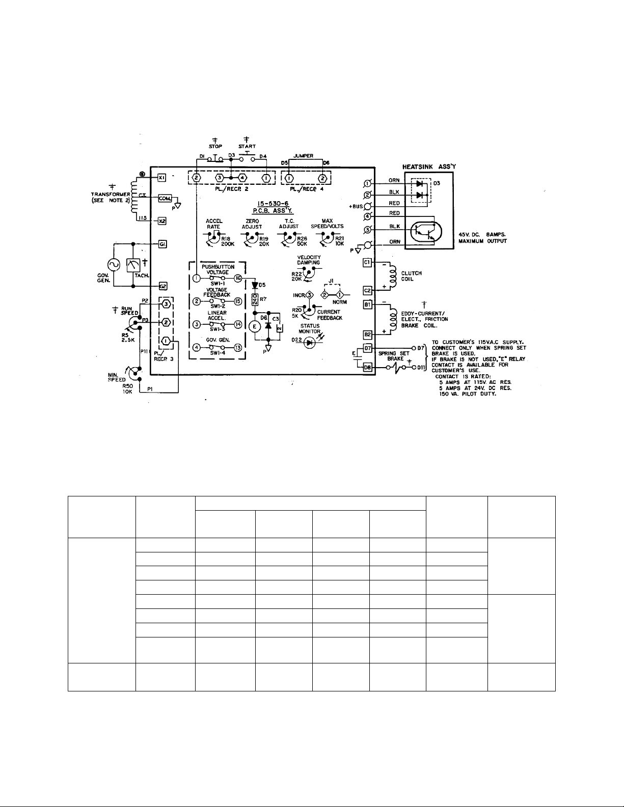
Figure 3-8b Schematic Diagram for Model 4050 Stamping Press Controller (15-539-0020)
Current
Assembly
Rated
Current
SW1 Contacts
Input
Transformer
Connections
1 2 3
4
0-3A
X X X X 27K
Tape Lead
3-4A
X O O O 40K
4-5A
O O X O 59K
5-10A
O O O X 62K
10-20A
X X X X 27K
Connect
(BLK)
20-35A
X O O O 40K
35-50A
O O X O 59K
50-70A
O O O X 82K
15-18-*
60A &
Higher
x x x x 27K
continued
(Model 4000 is the same except 15-530-5 PCB assembly is used. PCB assembly includes items shown
here is 15-529-19 heatsink assembly
56820
Model 4000 Stamping Press Controller with Torque Limit and Minimum Speed Adjustment 115V input
and 4.3 Adc output (15-533-1020)
Model 4050 Stamping Press Controller with Torque and Minimum Speed Adjustment 115V input and 8
Adc. Output (15-539-0020)
Transformer
Motor
Impedance
Lead
No. 3 (ORN)
Separately
15-203-3
Lead No. 3
(ORN) to
Lead No. 2
X- indicates closed contact O- indicates open contact
Page | 31
Page 32
Section 4
Operation
The Model 4050 stamping press controllers are easy to operate. However, a more detailed knowledge of
the controller’s functions will help you obtain the vest possible performance. Knowing how they work
will help you trouble shoot any problems that may arise. Before applying power to the controller please
read these operating instructions carefully.
Basic Controller Theory
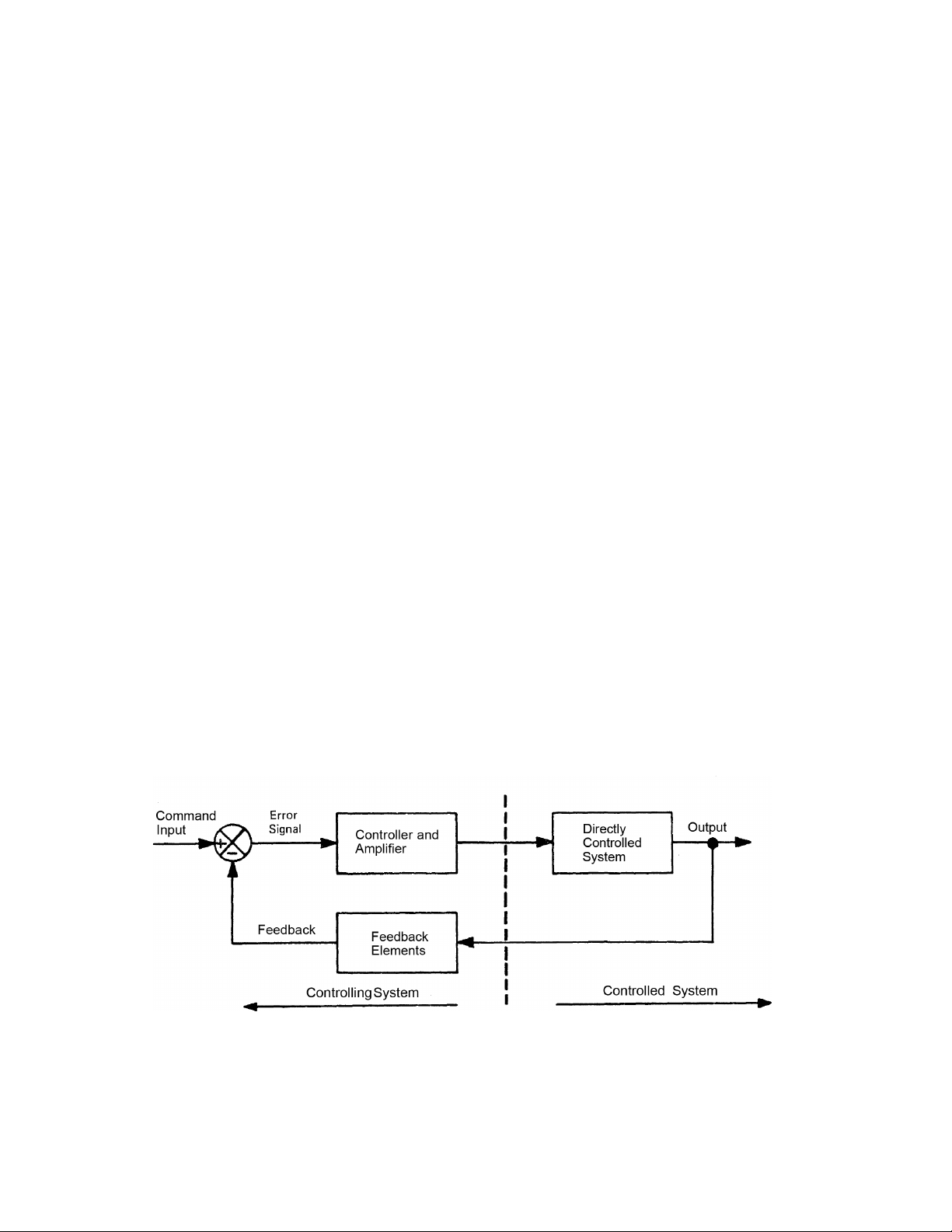
These are closed loop controllers. The output is measured, fed back and compared back differs from the
command, an error proportional to the difference is generated. The resultant error is used to increase or
decrease the output until it is equal to the command input until it is equal to the command input. A
simplified closed loop block diagram is shown in Figure 4-1.
A closed loop system consists of two parts, the controlling and the controlled systems. In the case of this
description, the controlling system is the Model 4050 stamping press controller and the controlled
system is the eddy current drive. The command input is a 0 to 9.1 Vdc signal, adjusted and set by the
operator when he turns the Run Speed/Min Speed potentiometers. The feedback signal is obtained from
the output shaft of the drive. The feedback voltage is directly proportional to speed. Whenever the
command signal is greater than the feedback, a positive error exists. The drive is not running fast
enough, and the positive error signal turns on the amplifier, in creasing the clutch coil excitation. The
reverse is true when the feedback exceeds the command. This indicates the drive is running too fast and
the controller is turned down. When the drive speed is at or near the desired speed, the difference
between the command input and the feedback is very small, resulting in a small error signal. At this
point the controller is regulating and adjusting the drive excitation to bring the speed to the set point.
Figure 4-1 Simple Closed Loop System
*if an external tach generator is employed it should be capable pf producing 40 to 60 volts and 5
milliamperes at 100% speed for a unit standard speed control.
Page | 32
Page 33

Any sudden load change would change the drive speed, change feedback voltage, increase the error
signal and result in a change in drive excitation to correct for the load change. In actual operation, the
voltage across the clutch coil is constantly varying to compensate for loads changes.
The Model 4050 stamping press controllers are somewhat more complex than the preceding
explanation, in that two feedback loops are connected. Both speed (velocity) feedback and clutch
voltage (current analog) feedback are used. The velocity feedback is used to provide the shaft speed
intelligence described above, and along with the current feedback, is used for damping and stability.
A block diagram for the basic speed controller version of the Model 4050 controller is shown in
Figure 4-2.
To operate the controller, three operator control devices are required: Stop and Start pushbuttons and a
Run Speed potentiometer (these operator controls are not supplied unless specified). Normally, on press
controllers a customer supplied Run contact is used in place of the Start/Stop pushbuttons. The start
pushbuttons/customer’s Run contact energizes the E relay, which holds itself in through a holding
contact. The E relay opens the brake output and connects the clutch coil. The operator can then set the
drive speed by turning the Run Speed potentiometer to a reference position on the knob corresponding
to the percent of maximum speed desired. The velocity feedback signal from the tachometer generator
causes the controller to regulate and hold the proper speed. To stop the controller, the operator presses
the Stop pushbutton or opens the customer’s Run contact. The E relay drops out, disconnecting the
clutch coil and connecting any brake that may be used.
Torque Limit Modification 15-44-2
For some applications of variable speed drives, it is necessary to limit the torque available to a machine
in order to prevent damage to the machine itself or its process. The adjustment range is from 50 to
150% of rated motor torque.
The input of the modification is a motor current feedback signal from a current transformer on one of
the motor lines. The current transformer assembly (15-203-3 or 15-18-8) includes the current
transformer and its required load resistor in a package for mounting by the customer. The motor current
signal is rectified, filtered and then fed to the Difference Amplifier. When it exceeds the Torque Limit
reference, a negative feedback signal is sent to the controller. The controller is “phased” back to the
point where the clutch excitation is such that the torque supplied by the motor remains at the preset
value of Torque Limit potentiometer R19 located on the modification PCB.
The torque limit response can generally be adjusted from underdamped to overdamped by the Torque
Limit Damping potentiometer R18 on the modification PCB. Also, in special applications with very high
load inertias, additional velocity damping is available by using the HI Damping pot.
*See Bill of Material for complete part number
Linear Acceleration Option
One of the optional features included in the Model 4050 stamping press controllers is the on-board
linear acceleration circuit. With the components mounted on the main PCB assembly, the circuit can be
Page | 33
Page 34

easily connected or disconnected by the Dip switch or by closing SW2 on the modification board. With
the switch open, acceleration is limited only by the torque limit circuit.
The purpose of linear acceleration is to slow down response to a change in command. Without linear
acceleration control, the drive will respond to operator speed adjustments very quickly, limited only by
the torque capacity of the drive. With the linear acceleration circuit, the output response of the
controller is held to a linear rate of change with respect to time. The circuit is adjustable from a nominal
3 to 90 seconds. When set at the minimum acceleration rate the drive will take at least 80 seconds to
accelerate from zero to full speed, following a linear ramp. When less than full speed is set, the time to
reach that speed is proportionally less. The controller programming chart on the connection diagram
shows hoe the circuit should be programmed.
Fixed Brake Option
A fixed brake option is available on all Model 4050 stamping press controllers. When the controller is
stopped, the E relay de-energizes, connecting the brake coil to terminals B1 and B2. The controller is
capable of putting out 45 Vdc, 8 amps continuous at these terminals. An electrically applied brake is
required, such as the eddy current brake. No adjustment of the brake excitation is available, unless you
install an external resistor in series with the brake coil to limit the voltage across the brake.
Spring Set Brake Option
All Model 4050 stamping press controllers figurations provide a normally open (NO) relay contact from
the E relay, wired to terminals D7 and D8 on the main PCB, 15-530-6. This contact is open whenever the
controller is stopped and is rated 115 Vac or 24 Vdc, 5 amps resistive load, 150 VA pilot duty. If a spring
set brake is not used, the E relay contact is available for any customer use within its rating.
Speed Trip Option
Model 4050 stamping press controllers equipped with a transformer can include the Speed Trip printed
circuit board for customer use. The PCB has no effect on the controller or drive unless its contacts are
connected into the controller circuit.
The trip circuit may be set to trip at a specific speed according to the setting of Speed Trip
potentiometer R4. The input signal is from leads G1 and G2 of the tachometer generator. The variable
generator voltage, which is proportional to speed, is used to obtain the desired trip speed by adjusting
the Trip Speed pot. The trip is executed by means of a relay, which has a set of normally open (NO) and
a set of normally closed (NC) relay contacts rated for 115 Vac at 10 amps. When the output speed of the
drive reaches the level of the Trip Speed pot, the relay is energized and the contacts switch.
Page | 34
Page 35

Figure 4-2 Model 4050 Controller Block Diagram
Page | 35
Page 36

Section 5
Start-Up and Adjustments
This section of the manual is intended to assist you in placing your Model 4050 stamping press
controllers into service. Before turning the power ON please read these instructions carefully.
Although the controller has been tested and inspected at the factory the following series of Power Off
test must be completed before turning power to the controller ON. After completing these tests, refer
to the Power On tests and proceed to the Preliminary Adjustment Procedure steps that apply to your
particular stamping press controller.
Tools Required
To simplify the start-up and adjustment procedure for the Model 4050 stamping press controllers, they
are equipped with an LED (light emitting diode). This LED enables the operator to set Maximum Speed
and Zero adjust with the use of only a small screwdriver. No other tools are required for start-up;
however, a multimeter, ammeter and stroboscope are desirable to obtain exact settings. The controller
will be hot when you are working on it; make sure your tools are well insulated. Do not switch meter
scales or ranges when the probes are connected to the controller.
Power Off Test
Before starting the ac motor or applying power to the controller, make the following visual inspections
and continuity checks. The disconnect switch should be locked out.
CAUTION: Alert all personnel in the area that the machine is being checked out and should be considered
running. Do not work alone. Rotating machinery and above-ground electrical potentials can be
hazardous. Your life may depend on prompt help, someone capable of stopping the machine and
disconnecting the ac power. Know where the Stop pushbutton and disconnect switch are located.
1. Visually inspect the machine and drive. Are they safe to operate and are all required guards and
safety devices installed and checked out?
2. Visually inspect the controller for any damage that may have occurred during shipment, such as
loose connections and damaged wire or components. Make sure that all electrical connections
are tight and not grounded or shorted. Look for individual strands that may be sticking out of a
lug or from a terminal.
3. Visually inspect the Operator’s controls (which are supplied by the customer) to see if they are
connected properly per the connection diagram. This includes the Run Speed pot R5 and the
Start and Stop pushbutton controls. Also, inspect each controller plug to make sure it is plugged
into the right receptacle and is locked in place. Check the connection diagram if there is a
question.
4. Visually inspect the PCB switch(s) for programming. The connection diagram includes the
programming chart.
Page | 36
Page 37

5. Disconnect the clutch (C1 & C2) and brake (B1 & B2) leads from the controller terminal strip.
Using an ohmmeter, check resistance between each lead and ground, and all other leads for
shorts. If a brake is not used, check to ensure that the leads are not inadvertently shorting out
inside of the drive.
Power On Test
Do not apply power until this procedure instructs you to do so. Follow the instructions; each step has a
purpose.
1. Check to make sure the machine is ready to be started and all personnel in the area are alerted.
The drive should remain uncoupled from the load during initial start-up.
2. Prepare to start the ac motor portion of the drive to check the direction of rotation. If the
machine can be damaged by reverse rotation, temporarily disconnect the output shaft. Checking
rotation is best done by having two people involved, one to operate the pushbuttons and the
other to wat the drive. Turn ON the ac power to the motor. Do not start the controller.
3. Bump the motor by starting and quickly stopping the motor. While the motor is coasting to a
stop, look into one of the large louvered air discharge grilles located on either side of the drive.
Observe the direction of rotation of the motor rotor and drum assembly. If rotation is not
correct, turn OFF the ac power and reverse any two of the tree motor leads (T1, T2, T3).
4. With ac motor ON, stat the ac motor. Do not start the controller. Let the ac motor run and
observe its operation. Listen for any abnormal noise and feel for excessive vibration. The clutch
portion of the drive should not be energized. With the output shaft disconnected, or with
machines having very little friction, the output shaft may turn over slowly. This is caused by
windage and bearing drag and is normal. Excessive torque at the output shaft is an indication of
mechanical problems. If any defect is detected, shut down immediately and correct the
problem. If the output shaft was disconnected in Step 2, turn OFF the ac power and reconnect
the shaft and replace the guards. Then turn on the ac power and restart the ac motor.
5. Ac power is normally connected to the controller whenever the ac motor is running, with power
from an isolation transformer, which can be a winding in the motor or a transformer that is
either mounted on the panel or shipped loose, that is connected to the load side of the motor
starter. If you have installed a disconnect device in the controller ac input leads, close it at this
time.
Start the controller by closing the customer’s run contact or pressing the Start pushbutton located on
the operator’s control panel. Turn the Run Speed potentiometer up (CW) until the output shaft begins
to turn. If the drive output shaft turns when the potentiometer is turned up, turn the potentiometer
back to zero (Full CCW) and proceed to step 6. Should the drive fail to run, turn to Trouble Shooting in
Section 6. The fault may be a simple wiring error, blown fuse or incorrect positioning of a plug or switch
contact.
Page | 37
Page 38

6. Checkout the operation of the machine before making any controller adjustments. Turn up the
Mechanical Unit Model Numbers
Velocity Damping Setting
Run Speed potentiometer and run the machine at some safe, reasonable speed. Carefully check
all parts of the machine to make sure it is functioning properly and that it is safe to continue.
Stop the drive, turn OFF the ac power and make any connections that are necessary. When
ready proceed to Preliminary Adjustments, and then to the Adjustment Procedure.
Set-Up Main PCB Assembly
This procedure s applicable to all Model 4050 stamping press controllers. After reading this section,
refer to the instructions for your specific controller and follow the steps in the order provided. In each
case the objective is to adjust the main PCB assembly first and then set up the 15-444-2 modification if it
is used. Six adjustments are found on the main PCB assembly. They are Zero Adjust, Max Speed/Volts,
Accel Rate, Velocity Damping, TC Adjust and Current Feedback. The six are grounded together at the
edge of the board opposite the terminal strip. The names are silk-screened next to the adjustments to
prevent error in selection. Each is a single turn potentiometer; 0% is full counter-clockwise (CCW) and
100% is full clockwise (CW). The drawings shoe an arrow pointing in the CW direction. The
potentiometers are adjusted at the factory during test to provide optimum performance on our test
drive. However, some minor variations exist between drives, due to manufacturing tolerances, which
may make it necessary to reset the adjustments.
Preliminary Adjustments
Perform the following preliminary adjustments (with no power applied to the controller)
1. Operator controls (supplied by customer unless specified)
a. Set the Run Speed potentiometer R5 to 0% (Full CCW)
b. Note location of Start and Stop pushbuttons
2. Main PCB 15-530-6
The pots used are screwdriver adjust, single turn pots. Do not use a screwdriver with a blade width
exceeding 1/8 inch.
a. Set the Accel Rate potentiometer R18 to 100% (Full CW)
b. Set the Zero Adjust potentiometer R19 to 0% (Full CCW)
c. Set the Max Speed/Volts potentiometer R21 to 0% (Full CCW)
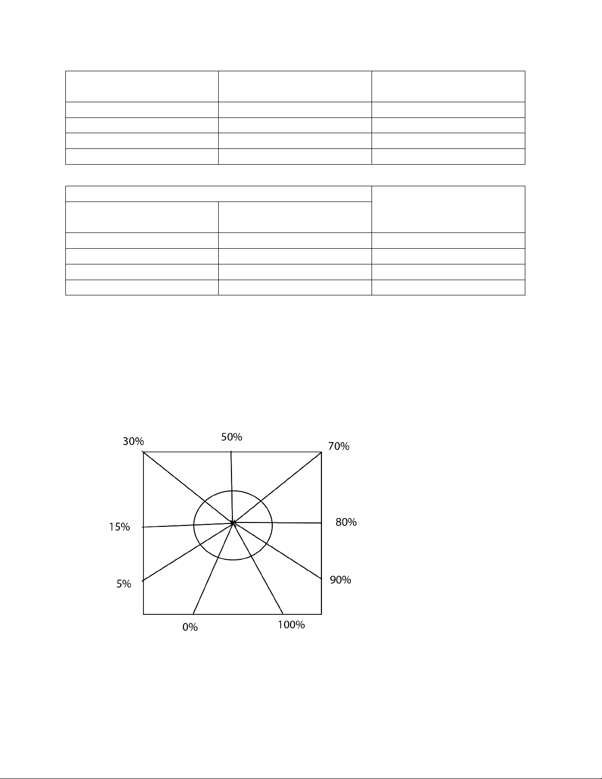
d. Set R22 as follows (see trimpot illustration)
e. Set the Time Constant (TC) Adjust potentiometer R26 as follows (see trimpot illustration)
f. Set the Current Feedback potentiometer R20 to 0% (Full CCW)
g. Set eth programming switches and jumper as indicated in the controller programming chart
on the connection diagram.
Page | 38
Page 39
AC/ACM/ACS/PD/VT
Fractional Hp (FHP)
AS/AT/AE/VT/EC
Fractional Hp
14/112/140
0%
181/182/184/186
18/21/132/160/180/210
50%
214/216/254/256
25/27/180/225/250/280
75%
280/320/360/440
75%
Mechanical Unit Model Numbers
Velocity Damping Setting
AC/ACM/ACS/PD/VT
AS/AT/AE/VT/EC
FHP/181/182
0%
184/186/214
14/18/112/132/140/180
15%
216/254/256/280
21/160/210
30%
320/360/440
25/27/180/225/250/280
100%
Fractional Hp (FHP)
*Typical product number stamped on mechanical unit nameplate:
1. A1-100214-0053, specific mechanical model is AC-214
2. B2-100210-0008, specific mechanical model is AS-21
Figure 5-1 Trimpot Illustration
3. Torque Limit Mod PCB 15-444-2 (for controllers with Torque Limit)
Note: Torque Limit Damping pot R18 and Torque Limit pot R19 are both 20-turn potentiometers. To
ensure a zero setting for starting adjustments, first turn them 20 complete turns CCW.
Page | 39
Page 40

a. Set the Torque Limit Damping potentiometer R18 at 50% CW.
b. Set the Torque Limit potentiometer R19 at 50% CW (this setting is approximately 150% of
rated motor torque)
c. Set HI Damping potentiometer R20 to 0% (Full CCW)
d. Check the drive nameplate for motor hp, voltage and current ratings. Set the Programming
switches and jumpers as indicated in Table 1 on the connection diagram for your rated
motor current.
4. Set panel mounted Min Speed potentiometer R50 or R55 to 0% (Full CCW).
Basic Speed Control (without Torque Limit)
Adjustment Procedure
CAUTION: To avoid personal injury or damage to the test equipment remove power before connecting
or disconnecting test equipment.
LED Set-Up
Since it is not always convenient to use a meter to monitor clutch voltage while setting up an eddy
current controller, a light emitting diode (LED) is included to provide a visual indication. The LED enables
the operator to set Maximum Speed and Zero Adjust with only a small screwdriver.
CONDITIONS: The Run Speed pot is at 0%. Zero Adjust is a 0%.
1. Install an ac ammeter in one of the ac motor leads to monitor motor current. This meter should
be used to monitor motor current during all of the following set steps to ensure that the motor
is not overloaded. The rated full load current of the ac motor is shown on the nameplate on the
motor. This value should not be exceeded during normal operation.
2. Turn ON the power to the drive and start the ac motor
3. Start the controller by closing the customer’s Run contact or with the Start pushbutton. Note
the location of the Stop pushbutton.
4. ZERO Adjust R19 with LED monitor- Slowly increase the Zero Adjust potentiometer R19 CW
while monitoring the LED, D22. When controller output is turned ON (or the drive shaft begins
to rotate), the LED should start flashing. Now just back off slowly until the flashing stops.
ZERO ADJUST R19, Alternate Method- This adjustment can be set to provide zero rpm or some minimum
speed greater than zero, as required by the machine operating requirements.
a. For zero rpm, turn the Zero Adjust potentiometer R19 CW until the output shaft just begins
to turn. Then back off on the control until the output shaft just stops turning. Stop and start
the controller a few times to be sure the drive shaft does not rotate
Page | 40
Page 41

b. For a minimum speed greater than zero, the LED cannot be used. Turn the Zero Adjust
potentiometer CW until the desired speed is obtained. For an accurate setting use a
tachometer or stroboscope.
5. MAX SPEED/Volts R21- this adjustment can be set to limit drive speed to its rated maximum or
to a slower speed as required by the machine process. An LED status monitor has been provided
on the main board to allow you to set the maximum speed without the use of a tachometer,
stroboscope or voltmeter. However, an alternate method of set-up using this equipment is given
to set the maximum speed point. The tachometer or stroboscope will give an accurate rpm
setting while the use of a voltmeter will give only an approximate speed setting. This is because
the voltmeter is measuring generator voltage instead of actual output rpm.
Max Speed/VOLTS R21 with LED monitor, Set the Run Speed potentiometer R5 at 100% (Full CW). The
drive should be loaded for best results. Set the Max Speed/Volts potentiometer R21 at 100% (FULL CW).
CAUCTION: Drive will go to top speed. The LED should be out when the drive is at top speed. With the
LED out, slowly turn the Max Speed/Volts potentiometer R21 CCW until the LED lights. This indicates
that the speed of the drive is in the regulating range of the controller. The clutch voltage should drop
below 45V. This will be approximately the maximum rated speed of the drive. The maximum speed
point will vary with different sized mechanical units.
There are two other conditions for which the LED will be out besides the drive being set for zero speed
or running wide open above the regulating range. These are whenever the “E” relay is de-energized (the
drive is stopped), or due to a wiring error, ground or some malfunction of the controller itself.
Max Speed/Volts R21, Alternate Methods
a. To set maximum rated speed with a tach or stroboscope; turn the Run Speed
potentiometer R5 to 100% (Full CW). Allow the drive to accelerate to full speed, turn the
Max Speed/Volts pot CW until the rated speed indicated is the same as the speed listed on
the nameplate of the mechanical unit.
b. To set approximate maximum speed with a voltmeter, connect a voltmeter (60 Vac scale)
across terminals G1 and G2. Turn the Run Speed pot R5 to 100% (Full CW) Allow the drive to
accelerate to full speed. With the drive at full speed, turn the Max Speed/Volts pot CW until
the meter reading ceases to rise. Back off the adjustment (CWW) until the meter reading
just begins to drop. This is the point of maximum speed.
c. To set a maximum speed that is less than rated maximum speed requires the use of a
tachometer or stroboscope indicator. This cannot be accomplished with the LED status
monitor. Turn the Run Speed potentiometer to 100% (FULL CW). Allow the drive to
accelerate to full speed. With the drive at full speed, slowly increase the Max Speed/Volts
potentiometer setting CW until the desired speed is indicated.
Page | 41
Page 42

6. Since there may be some interaction between the Zero Adjust and the Max Speed/Volts,
particularly if the minimum speed is other than zero, repeat steps 4 and 5 until the desired
speeds are obtained for both the zero and maximum positions of the Run Speed pot.
7. TIME CONSTANT (TC) ADJUST R26- The TC Adjust is used to set current feedback by using coil
voltage and a variable RC combination to simulate the different coil time constants of various
size drives. A trimpot illustration is provided on page 33 to facilitate the setting of this control.
Sufficient range has been provided for drive sizes up to 125 hp. Set your TC Control
appropriately for your individual drive size, as shown in the Preliminary Adjustments.
Settings are not critical and so many be “tuned” for each drive. High inertia applications can benefit
from higher than normal setting.
8. ACCEL RATE R18- The purpose of Linear Acceleration is to slow down drive response to an
increase in command. Without Linear Accel control, the drive will respond to operator speed
adjustments very quickly, limited only by the torque capacity of the drive. With the Linear Accel
circuit, the output of the controller is linear with respect to time. This circuit is adjustable from
3 to 80 seconds. When set at the slowest acceleration rate, the drive will take 80 seconds to
accelerate from zero to full rated speed, following a linear ramp. When less than full speed is
set, the time required to reach top speed is proportionally less.
The Linear Acceleration circuit may be activated or de-activated by setting the programming switches as
indicated on the programming switches as indicated on the programming chart on the connection
diagram.
To set Accel Rate: stop the controller with the Stop pushbutton. Turn the Run Speed potentiometer to
100% (Full CW). With the drive at a complete stop, push the Start pushbutton and time the interval
required for the drive to accelerate from zero to full speed. Adjust the Accel Rate potentiometer R18
CCW for a slower accel rate or CW for a faster accel rate.
NOTE: Only the Acceleration Rate is adjustable. The response of the controller to a reduced command is
instantaneous. The response of the drive to a decrease in command is a function of drive system load
and inertia.
9. Velocity Damping R22 (not applicable on models using Torque Limit mod PCB 15-444-2). Velocity
damping is the main type of damping used on the Model 4050 controllers. This damping signal is
derived from the speed feedback (governor generator) voltage. The rectified generator voltage
is a dc voltage that functions primarily as the negative feedback signal. The derivative of the
negative feedback is the velocity damping signal. The significant advantage to using a velocity
derivative damping signal is that a speed (velocity) damping signal actually detects speed
changes, and speed is the quantity being controlled. This results in a more accurate and faster
response to both load and reference changes than would results from the use of current
damping.
Page | 42
Page 43

The Velocity Damping setting specified under Preliminary Adjustments is a good starting point and will
result in satisfactory performance for most applications. This pot is used to match the controller’s
response to the drive’s response (drive response is a function of the clutch coil time constant and the
system inertia). The proper setting for this adjustment depends on the drive size and total load inertia.
Unusually high or low inertia loads may require further adjustment of the Velocity Damping pot to
obtain optimum system response. This must be done on a trail and error basis. If instability (speed
control becomes erratic) occurs at any setting increase (turn CW) slightly until the speed becomes
stable.
10. Current Feedback, R20*- Normal operation will not require use of this potentiometer. However,
there are some low inertia, light load, linear acceleration applications that may benefit from the
improved low end linearity that results from using Current feedback damping. Certain
applications are best met with a negative current feedback response which is slower in settling
and less likely to overshoot at low rpm’s. these types of drive applications require the addition
of current feedback to the velocity damping to obtain the desired performance. If you have one
of these applications, consult the factory because current feedback is normally not in the circuit.
It is connected by changing the jumper J1 from the Normal to the increased position. J1 is
located near the top of the main printed circuit board.
The current feedback should be used in addition to, but not in place of, the velocity damping. For most
applications some velocity damping is required for best response. A minimum setting of the Velocity
Damping adjustment of 50% is recommended when used with current feedback.
*The current feedback is actually a derivative signal, not a direct, proportional feedback signal.
11. Check motor current to make sure the motor is operating within it’s ratting. If motor current
exceeds the nameplate rating, shut it down and correct the problems. This completes the
adjustment procedure.
Control with Torque Limit Modification
NOTE: Follow Section 1, Basic Speed Control, beginning on page 34, through step 8 and step 10 (omit
step 9). Then proceed with the following steps that apply.
12. HI DAMPING R20- This pot is located on the Torque Limit modification board. It is used for
applications, such as stamping presses, where the load inertia is greater than 5 to 10 times the
drive inertia and Torque Limit is used. In these cases, turn the Velocity Damping pot R22 on the
main board to zero (Full CCW). Now adjust the HI Damping pot R20 on the modification board
until the proper response is achieved (neither oscillatory nor sluggish). If, however, maximum
CW is attained, and the system remains oscillatory, further damping may be obtained from R22
on the main board. The main PCB Velocity Damping pot R22 has about 75% of the damping
Page | 43
Page 44

range that the HI Damping pot R20 has on the modification board. However, they may be used
in combination on high inertia applications where increased damping is required.
13. Torque Limit PCB 15-444-2 (normal Load)
a. Apply the normal load to the drive.
b. Monitor the motor current. Since current is proportional to torque check your nameplate
for the rated motor current to determine the desired torque limit.
Example- if your drive is rated at 10 amps, and you want to limit the torque (150% of 10
amperes is 15 amperes), start the drive and note the maximum current on the ac ammeter
during acceleration. If the current is less than 150% of rated motor torque, increase the
Torque Limit setting R19 CW. If the current rating is too high, decrease the Torque Limit
setting CCW. Stop the unit and repeat the Start Up. Check on the ac ammeter during
acceleration. If the motor current during acceleration never reaches 150% of rated motor
current, increase the load and repeat current monitoring.
c. When the clutch is being torque limited, decrease the setting of the Torque Damping
potentiometer R18 CCW until instability (hunting) develops. Then increase the setting CW
until stability is obtained. Recheck the Torque Limit setting as described in step 13b and
readjust if necessary.
14. Torque Limit PCB 15-444-2 (If normal load cannot be applied)
a. Apply a load to the motor and note the motor current (IR) (a load of 50% of full load or more
is desirable).
15. Min Speed R50 or R55 (located on the panel) – with the Run Speed potentiometer at 0% (full
CCW), adjust the Min Speed potentiometer for the desired minimum speed.
16. Tachometer Indicator Calibration (located on rear of tach indicator) Note: With drive stopped,
zero the tach indicator with the screw adjust located on the face of the meter.
a. Start the drive and run the press. Turn the run Speed potentiometer CW until the drive is
operating at approximately ¾ of rated press speed.
b. Determine present speed by counting the stroking rate.
c. Adjust the tach indicator (adjusting screw located on rear of tach indicator) for correct
reading.
Note: After completing adjustment procedure, remove all jumpers across press builder’s
circuitry and restore drive to original condition.
17. Speed Trip R1 as a speed trip circuit (located on speed trip circuit PCB) Energize the drive. Adjust
the Run Speed potentiometer to obtain the desired speed at which the relay is to trip. Adjust
Trip Speed pot R1 until the trip circuit relay is just energized. The setting of the Trip Speed
potentiometer determines the speed at which the trip circuit relay trips (energizes)
Page | 44
Page 45

18. Check motor current to make sure the motor is operating within it’s rating. If motor current
exceeds the nameplate rating, shut it down and correct the problem. This completes the
adjustment procedure.
Section 6
Maintenance and Troubleshooting
Maintenance
Very little maintenance is required to keep the Model 4050 stamping press controllers in service.
Periodically, we suggest that you check the controller to make sure all terminal screws and other
connections are tight. Look for signs of trouble, such as burn spots on the boards, loose parts, worn out
switches or pushbuttons and any other abnormal condition. Correct any deficiency found. If you have a
question, consult Dynamatic at 800-548-2169.
The relays in the controller have a definite life, as do the potentiometers and switches. They are
designed for many years of average use, but your operation may call for more frequent switching.
Therefore, we suggest you stock replacements based on your type of operation. If you need help in
deciding which parts to stock, our Renewal Parts Department will help you. A recommended spare parts
list is included in the Instruction Sheets for your specific controller. This list is based on average
conditions.
Page | 45
Page 46

Troubleshooting
The possibility of component failures or other problems always exists. This section of the manual is
provided to assist you in finding the fault and making repairs. Our design philosophy is based on
assembly replacement. Trying to find a failed part on a printed circuit board is not economical when you
compare the cost of labor and down time with the cost of a replacement PCB assembly. Therefore, this
manual limits troubleshooting to the sub-assembly level. Check the obvious first. Are the plugs and
switches in the right position and is the power ON?
Model 4050 stamping press controllers are short circuit proof for the following conditions;
• Shorting of terminal C-1 to C-2
• Shorting of terminal B-1 to B-2
• Shorting of terminals C-1 or C-2 to earth ground
• Shorting of terminals B-1 or B-2 to earth ground.
Should any of these conditions occur the controller is self-protecting and damage or degradation to any
controller internal components will not happen. Blowing of fuses FU1 & FU2 may occur with some short
circuit conditions. Mechanical drive & control panel are assumed to be at earth ground.
CAUTION: Turn OFF ac power to the motor and controller before making tests, except when voltage
measurements are necessary. Only qualified personnel acquainted with safety procedures should
service this equipment.
If the drive will not run, we suggest you make these tests to check out the controllers:
1. With ac power removed, set your multimeter on the 250 Vac range. Measure controller
terminals X1 and X2. With power OFF you should read zero volts. Do not proceed until a zero
reading is obtained. Then pull fuses FU1 and FU2 (main PCB assembly) and check for blown
fuses. Replace if required and re-install FU1 and FU2 in the controller.
2. Turn ON the ac power and start the motor. Use the meter, set on the 250 Vac range, to check
for 115 Vac at terminals X1 and X2. Also check X1 to COM and X2 to COM for 57.5 Vac (nominal
voltage based on 115 Vac input). If voltage is not found at these terminals, trace the problem
back to the voltage source and correct it.
3. With ac power to the controller ON, remove the meter and switch to the 10 VDC range. Connect
the positive lead to the 100$ end of the Run Speed potentiometer and the negative lead to the
zero end. When looking at the back of the potentiometer, with the terminals down, the 100%
end is at the left and zero end on the right; you should read approximately 9 Vdc. If 9 Vdc is not
obtained, replace the main PCB assembly.
4. With ac power ON, connect the meter (10 Vdc) leads to terminals P3 and COM (P3 is positive).
You are now measuring the output of the Run Speed potentiometer. Controllers with the
selector switches on the cover should have the switch in the Run, Manual or Speed position.
Turn the Run Speed potentiometer from zero to 100% (full CW). The meter should indicate a
Page | 46
Page 47

voltage seeing from 0 to 9 Vdc. If you do not observe this voltage at P3, check or replace the
potentiometer or the main PCB assembly, one at a time.
5. Connect the meter, set on the 250 Vdc range, to Power Bus (+) and COM (-). These points are
push-on connector terminals located on the main PCB assembly near the E relay. With ac power
ON, you should read 45 to 80 Vdc. With a brake coil connected (Fixed Brake) it will be
approximately 50 Vdc. Without a brake coil it will be approximately 80 Vdc. If voltage is not
present, replace the main PCB assembly.
6. Leave the power ON. Connect the meter to terminals B2 (positive) and B1 (negative). A brake
voltage of 45 Vdc should be observed with a brake coil connected (Fixed Brake). Without a brake
coil connected this voltage will be approximately 80 Vdc. If no voltage is present, replace the
main PCB assembly.
7. If the correct voltage is found in steps 1 through 6, and the drive still will not run, connect the
meter across C2 (positive) and C1 (negative). Start the controller and turn the run speed
potentiometer to 100% (Full CW). If clutch voltage of approximately 45 Vdc is not observed,
replace the main PCB assembly. If voltage is found, the problem is not in the controller. Check
the wiring to the drive, the brushes and slip rings (if any) and the clutch coil.
If the drive runs at full speed, we suggest the following:
1. With the drive running, set your multimeter, on the 250 Vac range, on terminals G1 and G2. At
full speed, the generator voltage should be in the 40 to 65 Vac range. If no voltage is found, the
problem is in the tach generator or the leads to the controller. If the voltage is present, check
the Max Speed adjustment; and if that has no effect, replace the main PCB assembly.
2. Mechanical problems, such as a failed bearing or plugged air gap, can cause the unit to run at
full speed. Stopping the controller will not have any effect on the drive. It will run whenever the
motor is running.
If the fuse blows on a cold start, there may be a short or ground in the coil lead wires. Disconnect both
leads at the controller terminal strip (C! & C2) and check the resistance of the coil and resistance to
ground. Check the drive’s nameplate or instruction manual for the coil resistance. Resistance to ground
should be about 20 megohms. When using a megger, make sure both coil leads are disconnected from
the controller. Do not megger any portion of the controller.
If the drive is erratic or hunts, we suggest you check for loose connections, proper brush seating and
good slip ring surface (if used) and load pulsations that can reflect erratic load to the controller. If no
external cause is going, replace the main PCB assembly.
Renewal Parts and Service
Renewal parts for the Model 4050 stamping press controllers are stocked at Dynamatic. We suggest you
stock renewal parts to minimize down time. You alone can evaluate the cost of down time compared to
the cost of stocking spares. If you need help establishing stock levels, consult Dynamatic, 262-554-7977.
Page | 47
Page 48
The Instruction Sheets for you individual controller contain a list of recommended spares, based on
15-530-0006 Main PCB Assembly **
Qty
Part Number
Description
Legend
1
27-123-0001
Mini Jumper
J1
*2
32-028-0100
Fuse, 10 Amp, 250 V
FU1, 2
*1
53-398-0001
Replay, 4pdt, plug-in
E
15-444-0002 Torque Limit PCB Assembly **
1
15-263-0016
Standoff mounting kit
1 58-175-0004
Rocker switch, 4 pole dip
SW1
1
58-186-0001
Slide switch, dpdt
SW2
15-541-0001 through -0007 Panel Assembly **
Qty
Part Number
Description
Legend
1
15-530-0006
Main PCB (refer to PCB parts list Above)
1 15-444-0002
Torque Limit PCB assembly
*1
15-529-0021
Heatsink assembly, including Q1 & D3
*2
32-013-5092
Fuse, slob lo, .5 Amp, 250 V
FU3, 4
*1
15-248-380
Trip circuit assembly N 15-541-0001 Panel Mount with Transformer for 115 Volt Input
*1
64-361-0008
1kVA transformer, 50/60 Hz., 115 V Sec. CT
T1
15-541-0002 Panel Mount with Transformer for 208 Volt Input
*1
64-361-0002
1kVA transformer, 50/60 Hz., 115 V Sec. CT
T1
15-541-0003 Panel Mount with Transformer for 390 Volt Input
*1
64-361-0003
1kVA transformer, 50/60 Hz., 115 V Sec. CT
T1
15-541-0004 Panel Assembly with Transformer for 230/460 Volt Input
*1
64-361-0001
1kVA transformer, 60 Hz. 115 V Sec. CT
T1
15-541-0005 Panel Assembly with Transformer for 575 Volt Input
*1
64-361-0004
1kVA Transformer, 60Hz., 115 V Sec. CT
T1
15-541-0007 Panel Mount with Transformer for 208/230/460 Volt Input
*1
64-360-0016
Transformer, 50/60 Hz.
T1
average requirements.
Warranty controller failure will be handled by replacements. Technical assistance is always available
over the telephone, and field service engineers are available for start-up, trouble shooting and training
seminars at the published rates. Contact Dynamatic 262-554-7977.
The company maintains a Repair Service Department the works on a time and material basis. Controllers
returned under Warranty for repair will be repaired and returned with the original unexpired warranty
agreement continuing to be in effect.
Renewal Parts List
4050 Stamping Press Controller with A Transformer, Torque Limit and Trip Circuit
Page | 48
Page 49
4050 Stamping Press Controller with a Transformer and Torque Limit (Less Trip Circuit)
15-541-0021 through -0025 Panel Assembly **
Qty
Part Number
Description
Legend
1
15-530-0006
Main PCB (refer to PCB parts list Above)
1 15-444-0002
Torque Limit PCB assembly
*1
15-529-0021
Heatsink assembly, including Q1 & D3
15-541-0021 Panel Mount with Transformer for 115 Volt Input
*1
64-361-0008
1kVA transformer, 50/60 Hz., 115 V Sec. CT
T1
15-541-0022 Panel Mount with Transformer for 208 Volt Input
*1
64-361-0002
1kVA transformer, 50/60 Hz., 115 V Sec. CT
T1
15-541-0023 Panel Mount with Transformer for 390 Volt Input
*1
64-361-0003
1kVA transformer, 50/60 Hz., 115 V Sec. CT
T1
15-541-0024 Panel Assembly with Transformer for 230/460 Volt Input
*1
64-361-0001
1kVA transformer, 60 Hz. 115 V Sec. CT
T1
15-541-0025 Panel Assembly with Transformer for 575 Volt Input
*1
64-361-0004
1kVA Transformer, 60Hz., 115 V Sec. CT
T1
15-539-0019 Panel Mount with Torque Limit
Qty
Part Number
Description
Legend
1
15-530-0006
Main PCB (refer to PCB parts list Above)
*1
15-444-0002
Torque Limit PCB assembly
1 15-529-0021
Heatsink assembly, including Q1 & D3
15-539-0020 Panel Mount with Minimum Speed (Less Torque Limit)
1
15-530-0006
Main PCB Assembly
T1
*1
15-529-0019
Heatsink assembly, incl.. Q1 and D3
15-539-0019 Panel Mount with Torque Limit
Qty
Part Number
Description
Legend
1
15-530-0006
Main PCB (refer to PCB parts list Above)
*1
15-444-0002
Torque Limit PCB assembly
1 15-529-0021
Heatsink assembly, including Q1 & D3
15-539-0020 Panel Mount with Minimum Speed (Less Torque Limit)
1
15-530-0006
Main PCB Assembly
T1
*1
15-529-0019
Heatsink assembly, incl.. Q1 and D3
15-530-0005 Main PCB Assembly **
Qty
Part Number
Description
Legend
1
27-123-0001
Mini Jumper
J1
*2
32-018-4091
Fuse, 4Amp, 250 V
FU1, 2
4050 Stamping Press Controller without a Transformer
4050 Stamping Press Controller without a Transformer
4050 Stamping Press Controller
Page | 49
Page 50

*1
53-398-0001
Relay, 4pdt, plug-in
E
15-533-1019 Panel Mount with Torque Limit
1
15-530-0005
Main PCB Assembly (Refer to PCB parts list above)
*1
15-444-0002
Torque Limit PCB assembly
4 36-298-0010
Circuit board support
15-533-1020 Panel Mount with Minimum Speed (Less Torque Limit)
1
15-530-0005
Main PCB assembly (Refer to PCB parts list above)
4 36-298-0010
Circuit Board support
*Denotes minimum spare parts
**Denotes suggested spares when downtime is critical.
Page | 50
Page 51
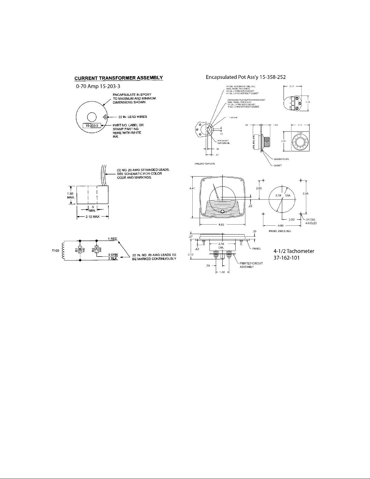
Loose Parts for 4050 Stamping Press Controller
Page | 51
Page 52

Drive Source International Dynamatic
7900 Durand Avenue, Bldg 3 Sturtevant, WI USA 53177
Toll Free: 800-548-21 69 Ph one: 262-554-7977
Email: [email protected]
Website: dynamatic.com
Page | 52
 Loading...