

Dyna-Glo SF70DGD User Manual
INDOOR/OUTDOOR PRODUCTS
KEROSENE PORTABLE
FORCED AIR HEATER
“USER’S MANUAL AND
OPERATING INSTRUCTIONS”
COMPLIES WITH UL733 AND
CAN/CSA/B140.0-03 AND
CSA B140.8-1967
carefully. This USER’S MANUAL has been designed to instruct you as to
the proper manner in which to assemble, maintain, store, and most
Please keep this manual for future reference.
CONSUMER : Retain this manual for future reference.
Questions, problems, missing parts? Before returning to your retailer, call our customer
service department at 877-447-4768 8:30 a.m. - 4:30 pm CST, Monday - Friday.
or email us at customerservice@ghpgroupinc.com
MODEL: SF70DGD
IMSFDG - IIA
NEVER LEAVE THE HEATER
UNATTENDED WHILE BURNING!
DANGER: IMPROPER USE OF THIS HEATER CAN RESULT IN SERIOUS INJURY OR DEATH
FROM BURNS, FIRE, EXPLOSION, ELECTRICAL SHOCK AND/OR CARBON
MONOXIDE POISONING.
WARNINGS:
1. RISK OF INDOOR AIR POLLUTION!
• Use this heater only in well ventilated areas. Provide at least a three-square foot (2,800 sq. cm.)
opening of fresh outside air for each 100,000 BTU/hr. of heater rating.
• People with breathing problems should consult a physician before using the heater.
• Carbon monoxide poisoning:
and/or nausea. If you have these signs, the heater may not be working properly.
Get fresh air at once! Have the heater serviced. Some people are more affected by carbon monoxide than others.
These include pregnant women, persons with heart or lung diseas
those at high altitudes.
• Never use this heater in living or sleeping areas.
headaches, dizziness
2. RISK OF BURNS / FIRE / EXPLOSION!
• NEVER use any fuel other than 1-K kerosene, #1/#2 diesel/fuel oil, JET A or JP-8 fuels in this heater.
• NEVER use fuel such as gasoline, benzene, paint thinners or other oil compounds in this heater.
(RISK OF FIRE OR EXPLOSION)
• NEVER
• NEVER ill hot.
CAUTION:
Hot while in operation. Do not touch. Keep children,
clothing and combustibles away from heater.
Minimum Clearances: Outlet: 8 feet (250cm) / Sides, top and rear: 4 feet (125cm)
• NEVER block air inlet (rear) or air outlet (front) of heater.
• NEVER use duct work in front or behind of heater.
• NEVER move, handle, service a hot, operating or plugged in heater.
• NEVER transport heater with fuel in it’s tank.
• When used with an optional thermostat or if equipped with a thermostat heater may start at any time.
• ALWAYS locate heater on a stable and level surface.
• ALWAYS keep children and animals away from heater.
• Bulk fuel storage should be a minimum of 25 ft. from heaters, torches, portable generators or other sources of ignition.
All fuel storage should be in accordance with federal, state or local authorities having jurisdiction.
3. RISK OF ELECTRIC SHOCK!
• on the model plate of the heater.
• Use only a three-prong, grounded outlet and extension cord.
• ALWAYS install the heater so that it is not directly exposed to water spray, rain, dripping water or wind.
• ALWAYS unplug the heater when not in use.
PROPOSITION 65 WARNING:
products of combustion of such fuels, contain chemicals known to the State of California to cause cancer,
birth defects and other reproductive harm.
MASSACHUSETTS RESIDENTS: Massachusetts state law prohibits the use of this heater in any
building which is used in whole or in part for human habitation. Use of this heating device in
CANADIAN RESIDENTS: Use of this heater shall be in accordance with authorities having
jurisdiction and CSA Standard B139.
NEW YORK CITY RESIDENTS: For use only at construction sites in accordance with applicable NYC
1
NEVER LEAVE THE HEATER
UNATTENDED WHILE BURNING!
CONTENTS OF USER’S MANUAL
ITEM
EDIUG YTEFAS - SNOITUACERP
1. INTRODUCTION
2. FEATURES
3. UNPACKING AND ASSEMBLY
4. FUELS
5. OVERVIEW OF HEATER DESIGN
6. FUELING YOUR HEATER
7. OPERATION
8. LONG TERM STORAGE OF YOUR HEATER
9. MAINTENANCE
10. TROUBLE SHOOTING GUIDE
11. WIRING DIAGRAM
12. SPECIFICATIONS
13. EXPLODED PARTS DRAWING
14. PARTS LIST
1. INTRODUCTION
Please read this USER’S MANUAL carefully. It will show you how to assemble, maintain, and operate the
heater safely and efficiently to obtain full benefits from its many built-in features.
PAGE #
1
2
2
3
3
4
4
5
6
6
10
11
11
12
13
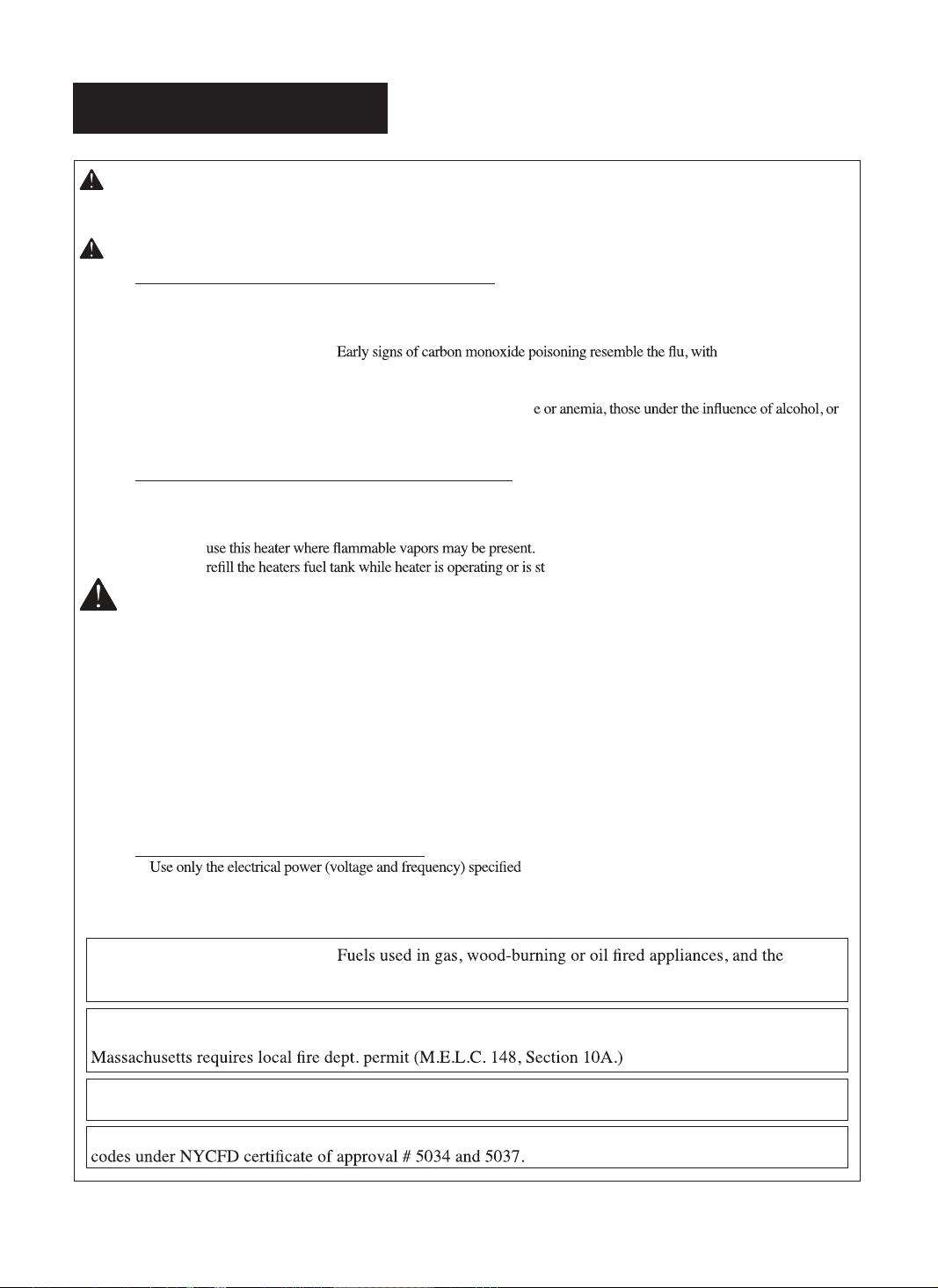
2. FEATURES
Hot Air Outlet
Front Guard
Heat Shield
Shell Supporter
Fuel Tank
Fuel Gauge
Shell Ring
Shell
Handle
Back Cover
Operating Switch
Lamp
Fuel Cap
Power Cord
Figure 1. SF70DGD Model
2
NEVER LEAVE THE HEATER
UNATTENDED WHILE BURNING!
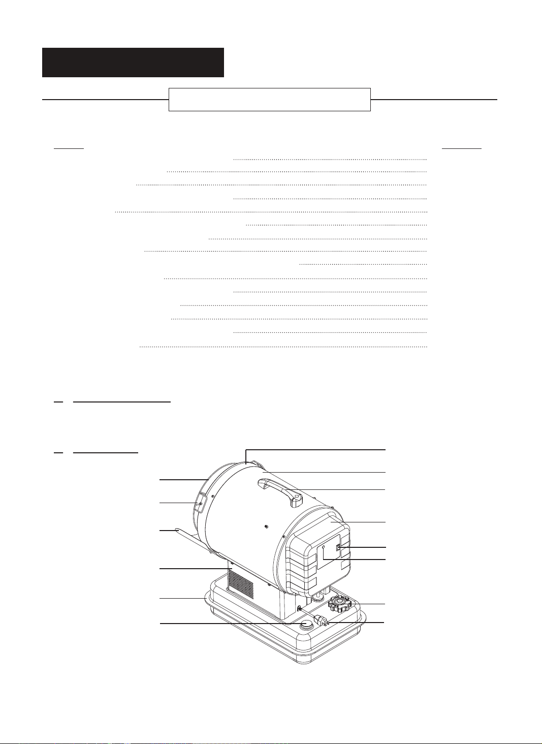
3. UNPACKING AND ASSEMBLY
1. UNPACKING
REMOVE THE HEATER AND ALL PACKING
MATERIALS FROM THE BOX.( Fig. 2 )
NOTE : Save the shipping carton and packing materials
for future storage.
2. ASSEMBLY
Tools Required
• Medium Phillips Screw driver.
1. Remove the pre-assembled Bolts on the shell
and shell ring.
2. Align the holes in the shell with two mounting
Shell Ring
Shell
Handle
Heat Shield
Figure 2. Packing Materials
Bolt
Handle
Remove Bolts
holes on the handle as shown in Figure3.
3. Secure handle with Bolts.
4. Align the holes in the shell ring with two
mounting holes on the heat shield as shown in
Figure 3.
5. Secure heat shield with Bolts.
Remove Bolts
CAUTION : DO NOT operate heater without heat
shield assembled to the heater.
Heat Shield
Bolt
The heat shield must attached to prevent any damage,
discoloration, or deformation to the floor.
Figure 3. Assembling Handle, Heat Shield
NOTE : Heater should be inspected before each use, and at least annually by a qualified service person.
4. FUELS
For optimal performance of this heater, it is strongly suggested that 1-K kerosene be used. 1-K kerosene has
been refined to virtually eliminate contaminants, such as sulfur. Which can cause a rotten egg odor during the
operation of the heater. However, #1/#2 diesel/fuel oil, JET A or JP-8 fuels may also be used if 1-K kerosene is
not available. Be advised that these fuels do not burn as clean as 1-K kerosene, and care should be taken to
provide more fresh air ventilation to accommodate any added contaminants that may be added to the heated
space. #2 diesel/fuel oil heavier than 1-K kerosene in extreme cold temperatures without nontoxic anti-icer
additives will not ignite properly. When diesel fuel is used for this heater, small amount of smoke may occur at
the ignition and turn off time.
KEROSENE SHOULD ONLY BE STORED IN A BLUE CONTAINER THAT IS CLEARLY
MARKED “KEROSENE”. NEVER STORE KEROSENE IN A RED CONTAINER.
Red containers are associated with gasoline.
NEVER
store kerosene in the living space. Kerosene should be stored in a well ventilated place outside the
living area.
NEVER
use any fuel other than 1-K kerosene (#1/#2 diesel/fuel oil, JET A or JP-8 fuels are acceptable substitutes)
NEVER use fuel such as gasoline, benzene, alcohol, white gas, camp stove fuel, paint thinners, or other oil
compounds in this heater. These are volatile fuels that can cause an explosion or uncontrolled flames.
NEVER store kerosene in direct sunlight or near a source of heat.
NEVER use kerosene that has been stored from one season to the next. Kerosene deteriorates over time.
“OLD KEROSENE” WILL NOT BURN PROPERLY IN THIS HEATER.
3
NEVER LEAVE THE HEATER
UNATTENDED WHILE BURNING!
5. OVERVIEW OF HEATERS DESIGN
The Fuel System :
This heater is equipped with a high-pressure electronic pump. The pump draws fuel up from the fuel tank to
the nozzle in the burner head. It is sprayed into the combustion chamber in a fine mist where it is mixed
with air for combustion.
The Air System :
A blower motor assembly forces air around the combustion chamber, where it is super-heated and forced
out the front of the chamber. A cooling fan blows air up and around the chamber during operation and also
runs during the cool-down period.
The Ignition System :
The electronic ignitor sends High voltage to a specially designed Spark Plug.
The Spark Plug ignites the fuel and air mixture described above.
The Safety System :
A. Temperature Limit Control : This heater is equipped with a Temperature Limit Control designed to turn
off the heater should the internal temperature rise to an unsafe level. If this
device activates and turns your heater off it may require service.
MODELS
SF70DGD
Once the temperature falls below the reset temperature you will be able to start your heater.
B. Electrical System Protection :
C. Flame-Out Sensor :
D. Shock(earthquake) automatic shut-off Device : This Heater is equipped with Tip Over switch,
In case that earthquake more than 5magnitude happens
or that heater inclined 5~10 degrees.
Heater will be shut-off by Tip Over switch for safety.
(Refer to Page 10“Trouble Shooting Guide”)
The heater uses photocell to see the flame in the combustion chamber.
Should the flame extinguish, the sensor will stop electrical current and the
heater will shut off.
Internal Shut-Off Temp. Reset Temperature
Plus/Minus 10 Degrees Plus/Minus 10 Degrees
176˚F/80˚C 158˚F/70˚C
The heater's electrical system is protected by a fuse mounted to the
PCB assembly that protects the system components from damage.
If the heater fails, check the fuse first, and replace if necessary.
6. FUELING YOUR HEATER
NEVER FILL THE HEATER FUEL TANK IN THE LIVING SPACE : FILL THE TANK OUTDOORS.
DO NOT OVERFILL YOUR HEATER AND BE SURE HEATER IS LEVELED.
IMPORTANT NOTICE REGARDING FIRST IGNITION OF HEATER :
The first time you light the heater, it should be done outdoors. This allows the oils, etc. used in
manufacturing the heater to burn off outside.
WARNING!! :
NEVER REFILL HEATER FUEL TANK WHEN HEATER IS OPERATING OR STILL HOT.
4

NEVER LEAVE THE HEATER
UNATTENDED WHILE BURNING!
7. OPERATION
A.) VENTILATION
RISK OF INDOOR AIR POLLUTION/USE HEATER ONLY IN WELL VENTILATED AREAS.
Provide a fresh air opening of at least three square feet (2,800 sq. cm) for each 100,000 BTU/Hr.
rating. Provide extra fresh air if more heaters are being used.
Example : A SF70DGD heater requires one of the following:
• a two-car garage door raised six inches (15.24 cm)
• a single-car garage door raised nine inches (22.86 cm)
• two, thirty-inch (76.20 cm) windows raised fifteen inches (38.1 cm)
B.) OPERATION
TO START HEATER
1. Fill the tank with kerosene until needle on fuel gauge points to "F".
2. Be sure fuel cap is secure.
3. Plug power cord into three prong, grounded extension cord into three prong 120V grounded outlet.
The extension cord should be at least six feet long.
Extension cord wire size requirements are as follows:
• 6 to 10 feet (1.8 to 3 meters ), use 18 AWG wire.
• 11 to100 feet (3.4 to 30.4 meters ), use 16 AWG wire.
• 101 to 200 feet (30.8 to 61 meters), use 14 AWG wire.
4. Push the Operating Switch to the "ON" position. The power indicator lamp will light
and the heater will ignite after the fan runs for a while. (approx.14sec.)
NOTE : The electrical components of this heater are protected by a fuse mounted in the PCB board.
If the heater fails to fire, check this fuse first, and replace if necessary. Also check the power
source to be sure that the proper voltage is being provided to the heater.
NOTE : In case of the following occurrences:
- Heater exhibits abnormal sputtering sound in the electronic pump while attempting to ignite.
- After filling up of the fuel tank, heater fails to properly ignite during its initial attempt.
- When user attempts to ignite heater following a previously failed ignition attempt with an
empty fuel tank.
- When the flow of fuel is blocked by air that is residing within the fuel line, in these cases,
one should try multiple ignition attempts on their heater.
The occurring noise is a direct result of the heating process as the heater’s pump pushes air
from the fuel line.
The noise should quickly decrease following the ignition of your heater.
It is also not unusual for slight smoke or flames to briefly be seen from the hot air outlet
after heater has ignited.
STOP HEATER
TO
1. Turn the Operating Switch to "OFF" position. Combustion will stop, and the Cooling Cycle
(approx. 7 minutes) will begin.
2. When cooling Cycle is completed (fan stops running), it is safe to unplug the heater.
• Unplugging the heater before the Cooling Cycle has ended may cause overheating,
damage to the heater, and could void the warranty.
5
NEVER LEAVE THE HEATER
UNATTENDED WHILE BURNING!
CAUTION : Do not disconnect the power source or unplug the power cord until the cooling cycle has
been completed!
TO RESTART THE HEATER
1.Wait 10 seconds after cooling cycle has completed.
2. Turn the Operating Switch to "ON" position.
3. Be sure to follow all starting procedure precautions.
CAUTION : DO NOT operate heater without heat shield assembled to the heater.
Temperature of the floor is hot while in operation. Use the heater without heater shield,
will cause deformation or discoloration of the floor.
CAUTION : NEVER use an accessory thermostat with this heater.
Accessory thermostat will bypass the cooling cycle after the heater is shuts off
and damage the heater.
8. LONG TERM STORAGE OF YOUR HEATER
• Unscrew fuel cap.
• Remove Kerosene from the tank by using an approved siphon pump.
• Rinse and swirl the kerosene inside the fuel tank by using a small amount of kerosene.
• Make sure the tank is completely empty.
Never leave kerosene in the tank over a long period time because using old kerosene can damage the heater.
Store heater in a dry, well-ventilated area
• Be sure that the storage area is free of dust and corrosive vapors. Repack the original shipping material.
keep the User's Manual in an easily accessible place.
9. MAINTENANCE
WARNING!! : NEVER SERVICE HEATER WHILE IT IS PLUGGED IN OR
WHILE HOT!
USE ORIGINAL EQUIPMENT REPLACEMENT PARTS.
Use of third party or other alternate components
will void warranty and may cause unsafe operating
conditions.
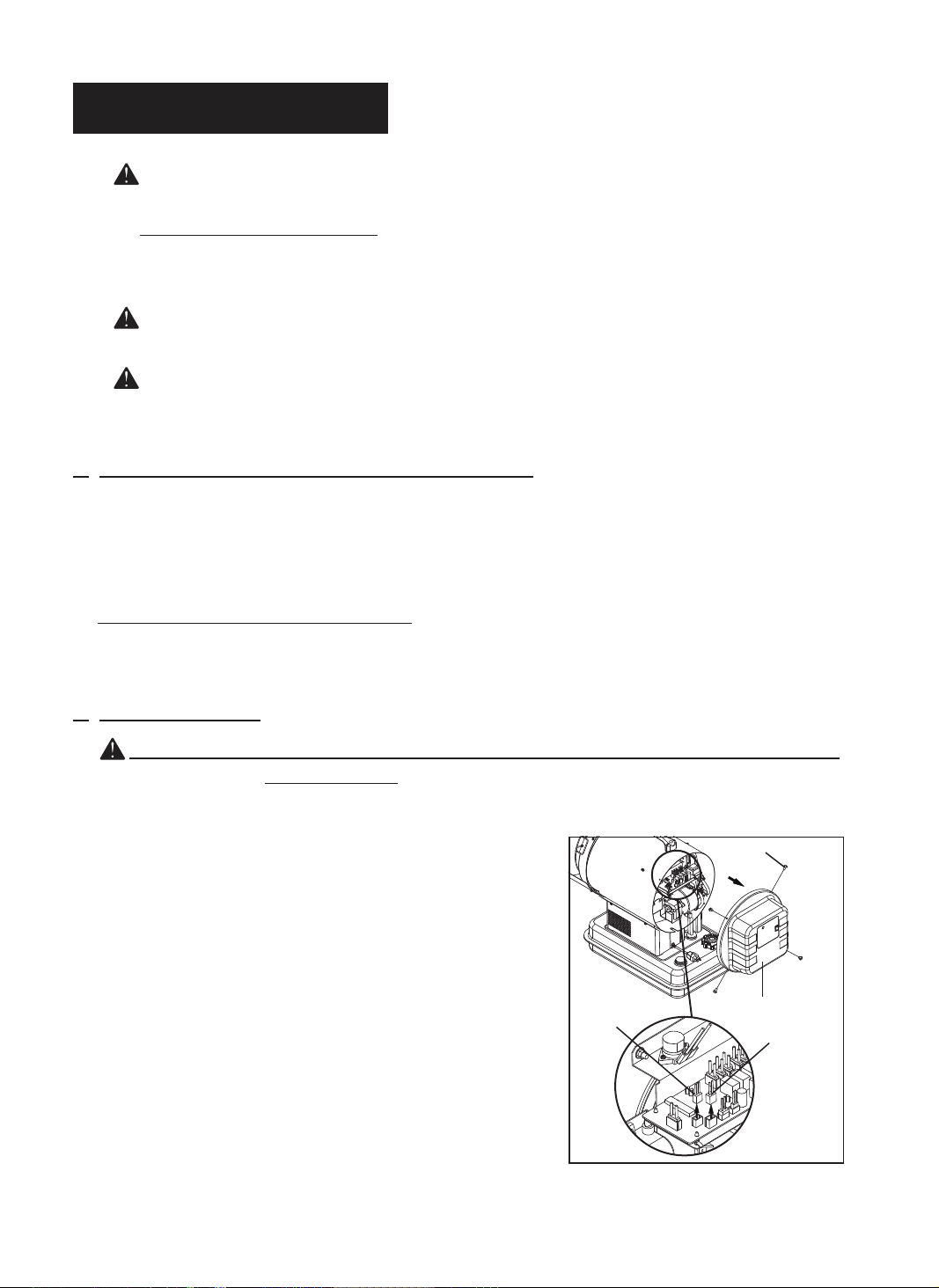
A) BACK COVER REMOVAL
1) Remove 4 Screws along circumference of the Back Cover.
2) Disconnect Operating Switch Wire and Display PCB
wire from PCB Board.
3) Remove Back Cover.
B) FUEL TANK
Flush every 200 hours of operation or as needed
(See above,8.Long term storage of your heater)
Screw
Display PCB
wire
Figure 4. Back Cover Removal
Back Cover
Operating Switch
wire
6
NEVER LEAVE THE HEATER
UNATTENDED WHILE BURNING!
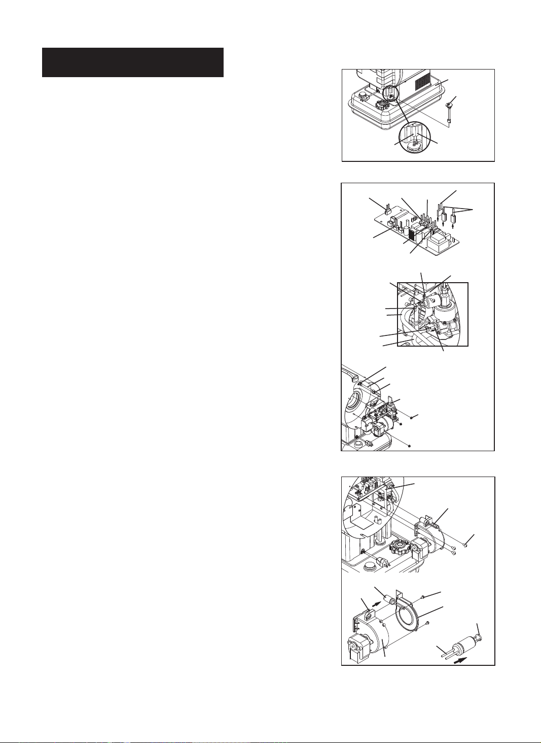
C) FUEL FILTER IN FUEL TANK
Clean twice per heating season or as needed
1) Pull Fule Line & Fuel Return Line off from Fuel Filter neck.
2) Turn Fuel Filter 90˚ to counter clockwise and pull to remove.
3) Wash Filter with clean kerosene and replace in tank.
4) Attach Fuel Line & Fule Return Line to Fuel Filter neck.
Fuel Tank
Fuel Filter
Fuel Line
Fuel Return Line
Figure 4. Tank Fuel Filter Removal
Cooling M/T
Wire
Burner
Supporter
Power
Wire
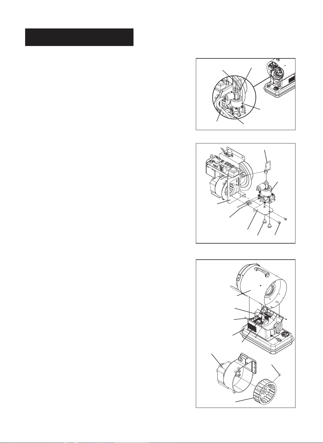
D) BURNER FULL ASSEMBLY REMOVAL
1) Remove Back Cover(See Page 6)
2) Disconnect wires from PCB board as shown in Figure 5.
3) Remove Earth Wire from Burner Supporter with medium
phillips screwdriver.
4) Loosen Clamps with long nose plier and remove Fuel Return
RPM Sensor
Wire
PhotoCell
Wire
Blower M/T
Sol. Valve Nipple
Pump
Wire
Valve
Wire
Wire
Igniter
Wire
Earth Wire
Line from nipple of the Solenoid Valve and remove Fuel Line
from nipple of the Electronic Pump.
5) Disconnect Limit Control Wire from Limit Control as shown
in Figure 5.
6) Remove 3nuts with 8mm socket wrench and remove
Burner Full Assembly from Shell Insulator.
E) PHOTOCELL
Figure 5. Burner Full Assembly Removal
Clean Photocell annually or as needed.
1) Remove Back Cover(See Page 6)
2) Disconnect Blower M/T & Photocell Wires from PCB
Board.(See Figure 5)
3) Remove 3 screws with medium phillips screwdriver
Clamp
Fuel Return
Line
Clamp
Fuel Line
Limit Control
Shell Insulator
Limit Control Wire
Burner Full Assembly
Nut
Burner Supporter
Electronic Pump Nipple
Blower Motor
Assembly
Screw
and remove Blower Motor Assembly from Burner Supporter.
4) Remove 2 screws with medium phillips screwdriver and
remove Cover Blower from Body Blower.
5) Slide to arrow direction and Remove Photocell from
holder with hand as shown in figure 6.
6) Push Photocell Wire to arrow direction.
7) Clean Photocell Lens with cotton swab.
If Photocell Lens is damaged, Replace new one.
8) Replace Photocell to holder and Cover Blower to Body Blower.
9) Replace Blower Motor Assembly to Burner Supporter.
10) Replace Blower M/T & Photocell Wires and Back Cover.
Photocell
Holder
Body Blower
Photocell
Wire
Screw
Cover Blower
Photocell
Lens
Figure 6. Photocell Removal
7
NEVER LEAVE THE HEATER
UNATTENDED WHILE BURNING!
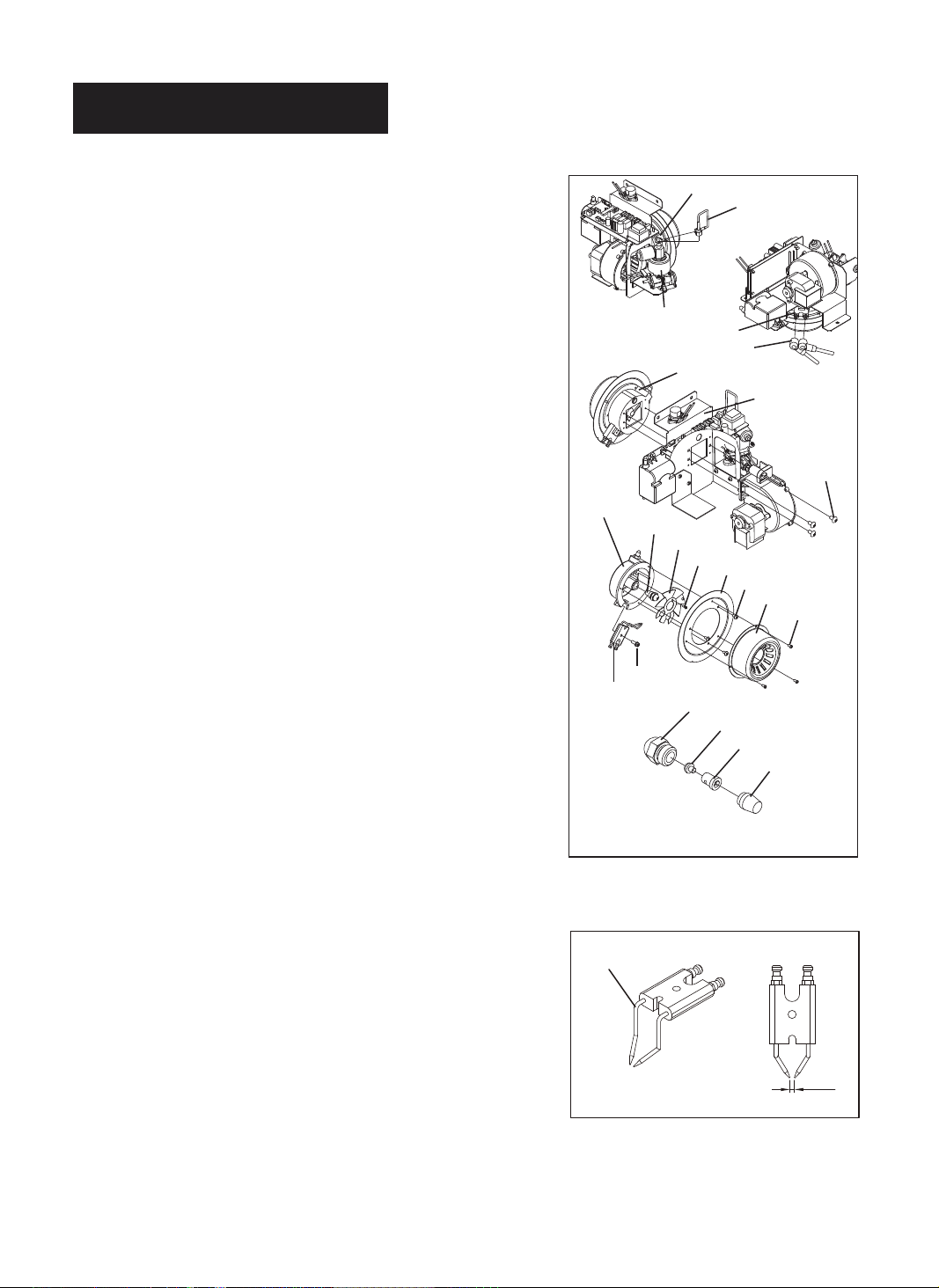
F) NOZZLE
Remove dirt in Nozzle or replace as needed
1) Remove Back Cover.(See Page 6)
2) Remove Burner Full Assembly.(See Page 7)
3) Remove Fuel Pipe from Electronic Pump and Burner
Body using 12mm wrench.
4) Remove Ignitor Wire from Spark Plug.
5) Remove 3 screws with medium phillips screwdriver
and remove Burner Assembly from Burner Supporter.
6) Remove 3 screws with medium phillips screwdriver
and remove Diffusion Cap from Burner Insulator.
7) Remove 3 screws with medium phillips screwdriver
and remove Burner Insulator from Burner Body.
8) Remove 1 screw with medium phillips screwdriver
and remove Burner Blade from Burner Body.
9) Remove 1 screw with medium phillips screwdriver
and remove Spark Plug from Burner Body.
10) Carefully remove Nozzle from Burner Body using
16mm socket wrench.
11) Disassemble Nozzle as shown in Figure 7.
* Turn Filter counterclockwise with wrench
and remove from Head.
* Turn Holding screw counterclockwise with
3/16" allen wrench and remove from Head.
12) Clean each Nozzle parts thoroughly with clean kerosene.
* Inspect Nozzle for damage.
If damaged or clogged, replace Nozzle.
13) Reassemble Nozzle & replace to Burner Body.
14) Replace Spark Plug,Burner Blade and Burner Insulator
to Burner Body.
15) Replace Diffusion Cap to Burner Insulator.
16) Replace Burner Assembly to Burner Supporter.
17) Replace Ignitor Wire to Spark Plug and Fuel Pipe to
Electronic Pump and Burner Body.
18) Replace Burner Full Assembly and Back Cover.
Burner Body
Electronic Pump
Spark Plug
Ignitor Wire
Burner Assembly
Burner Body
Nozzle
Burner Blade
Screw
Screw
Spark Plug
Head
Swirler
Nozzle disassembling
Figure 7. Nozzle Removal
Fuel Pipe
Burner
Supporter
Screw
Burner Insulator
Screw
Diffusion Cap
Screw
Holding Screw
Filter
G) SPARK PLUG
Clean and regap every 600 hours of operation.
or replace as needed.
1) Remove Spark plug from Burner Body.
(See above procedures)
2) Clean and regap Spark Plug electrodes to 3.5mm gap.
3) Replace Spark Plug to Burner Body.
8
Plug Electrode
GAP
Figure 8. Spark Plug Gap
NEVER LEAVE THE HEATER
UNATTENDED WHILE BURNING!
H) FUEL PIPE
Tightening Fuel Pipe annually or as needed.
1) Remove Back Cover.(See Page 6)
2) Tighten Fuel Pipe at Electronic Pump and at Burner
Body using 12mm wrench.
3) Inspect Fuel Line for damage.
If damaged or cracked, Replace Fuel Line.
Fuel Pipe
Burner Body
I) ELECTRONIC PUMP
Replace Electronic Pump if broke or damaged.
1) Remove Back Cover.(See Page 6)
2) Remove Burner Full Assembly.(See Page 7)
3) Remove Fuel Pipe from Electronic Pump and Burner Body
(See page 7)
4) Remove 2 screws with medium phillips screwdriver.
and remove Pump Supporter from Burner Supporter.
5) Remove 2 bolts with medium phillips screwdriver
and remove. Electronic Pump from Pump Supporter.
6) Inspect Electronic pump for damage or break down.
If break down or damaged, replace Pump.
7) Replace Electronic Pump to Pump Supporter and
to Burner Supporter.
8) Replace Fuel pipe to Electronic pump and Burner body.
9) Replace Burner full assembly & Back Cover.
J) FAN BLADES
Clean every season or as needed.
COOLING FAN
1) Remove Back Cover.(See Page 6)
2) Remove Burner Full Assembly.(See Page 7)
3) Remove 4 screws with medium phillips screwdriver
and remove Heater Assembly from Shell Supporter.
4) Slip Cooling Fan off from Cooling Motor shaft.
5) Clean Fan using a soft cloth moistened with kerosene
or solvent.
6) Dry Fan Blade thoroughly.
7) Replace Fan and Heater Assembly.
8) Replace Burner Full Assembly and Back Cover.
Electronic Pump
Fuel Return Line
Fuel Line
Figure 9. Tighten Fuel Pipe
Fuel Pipe
Electronic
Pump
Burner
Supporter
Pump Wire
Pump Supporter
Bolt
Screw
Figure 10. Electric Pump removal
Heater Assembly
Cooling Fan
Shell Supporter
BLOWER FAN
1) Remove Back Cover.(See Page 6)
2) Remove Burner Full Assembly.(See Page 7)
3) Remove Photocell from holder.(See Page 7)
4) Use 2mm allen wrench to loosen set screw
and slip Blower Fan off from Blower Motor shaft.
5) Clean Fan using a soft cloth moistened with kerosene
or solvent.
6) Dry Fan Blade thoroughly.
7) Replace Fan and Photocell.
8) Replace Burner Full Assembly and Back Cover.
9
Screw
Cooling Motor
Blower Motor
Set Screw
Blower Fan
Figure 11. Fan Removal
NEVER LEAVE THE HEATER
UNATTENDED WHILE BURNING!
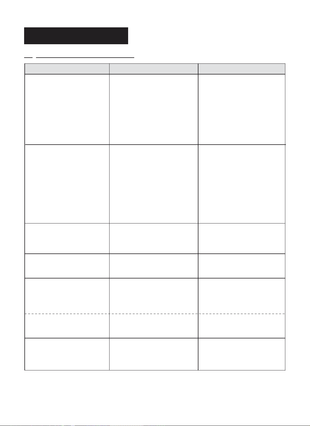
10. TROUBLE SHOOTING GUIDE
TROUBLE POSSIBLE CAUSE CORRECTIVE ACTION
Heater ignites but Control PCB
Assembly shuts heater off after
a short period of time.
(Indicater Lamp is flickering
once per 3sec.)
1. Dirty Fuel Filter.
2. Dirt in Nozzle.
3. Dirty Photocell Lens.
4. Photocell not properly installed.
(Not seeing the flame)
5. Bad electrical connection between Photocell
and Control PCB Assembly.
6. Defective Photocell.
7. Defective Electronic Pump.
8. Temperature limit control device is
overheated.
1. Clean Fuel Filter, Page 7.
2. Clean Nozzle, Page 8.
3. Clean Photocell Lens, Page 7.
4. Make sure Photocell is properly seated in
holder, page 7.
5. Check electrical components See wiring
diagram, Page 11.
6. Replace Photocell, page 7.
7. Replace Electronic Pump, Page9.
8. Turn operating switch to "OFF" and allow
to cool(about 10 min.)
Heater will not ignite but
motor runs for a short period
of time.
(Indicater Lamp is flickering
once per 3sec.)
Heater ignites but Heater shuts off
suddenly
(Indicator Lamp is flickering
twice per 3sec.)
Heater does not turn on and
the Indicator lamp is not light.
Flame is unstable and/or
soot occurs from hot air outlet
and heater shuts off
(Indicator Lamp is flickering
once per 3sec.)
1. No fuel in tank(completely empty)
2. Carbon deposits on Spark Plug and/or
improper gap.
3. Dirty Fuel Filter.
4. Dirt in Nozzle.
5. Water in Fuel Tank.
6. Bad electrical connection between Ignitor
and Control PCB Assembly.
7. Ignitor Wire is not propely attached to Spark
Plug.
8. Defective Electronic Pump.
9. Defective Ignitor.
1. Shuts off by external shock or inclined
place.
1. No electrical power
2. Blown fuse
1. Dirt in Nozzle.
2. Water in Fuel Tank.
3. Fuel leak at Fuel Pipe or Fuel Lines.
4. Defective Electronic Pump.
1. Fill tank with kerosene.
2. Clean & regap Spark Plug, See Page 8.
3. Clean Fuel Filter, Page 7.
4. Clean Nozzle, Page 8.
5. Flush fuel tank with clean kerosene, Page 6.
6. Check electrical components See wiring
7. Attach Ignitor wire to Spark Plug.
8. Replace Electronic Pump, Page 9.
9. Replace Ignitor.
1. Check whether heater is used at flat place
1. Check to insure heater cord and extension
2. Replace PCB board
1. Clean Nozzle, Page 8.
2. Flush Fuel Tank with clean kerosene, Page 6.
3. Tighten Fuel Pipe or replace Fuel Lines,
4. Replace Electronic Pump, Page 9.
diagram, Page 11.
See Spark Plug, Page 8.
and reset.
cord are plugged in. Check power supply.
Page 9.
(Indicator Lamp is flickering
three times per 3sec.)
Heater makes sputtering noise
and will not ignite.
(Indicater Lamp is flickering
once per 3sec.)
1. Blower Fan is obstructed or loosen.
2. Defective Blower Motor.
1. No fuel in tank.
2. Air in Fuel Pump or come into Fuel Line.
10
1. Remove any obstructions or tighten Blower
Fan, Page 9.
2. Replace Blower Motor.
1. Fill tank with kerosene.
2. Try ignition one more try.
(See Note, page 5)
NEVER LEAVE THE HEATER
UNATTENDED WHILE BURNING!
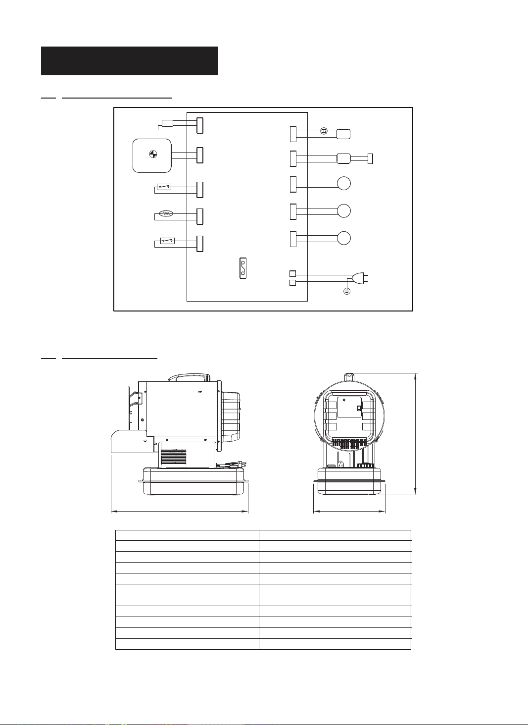
11. WIRING DIAGRAM
BLOWER FAN
RPM SENSOR
DISPLAY PCB
POWER LAMP
(LED)
OPERATING
SWITCH
PHOTO CELL
VIBRATION
SWITCH
12. SPECIFICATION
BLK
RED
YEL
CN1 BHI
BLUE
CN12
WHITE
(Dis 3P)
CN8
BLACK
CN5
WHITE
CN9
WHITE
C
O
T
O
L
FUSE
T5A/125Vac
PN
C
BR
CN7
RED
CN4
WHITE
CN13
BLACK
CN3
YELLOW
CN10
BLUE
CN1
(AC1)
CN2
(AC2)
BHI
LIMIT CONTROL
(OVERHEAT THERMOSTAT)
BLACK
WHITE
E/P
IGNITOR
I.G
SOL.
B/M
C/M
CASE
EARTH
ELECTRONIC
PUMP
SPARK PLUG
SOLENOID
VALVE
BLOWER
MOTOR
COOLING
MOTOR
POWER
120Vac/60Hz
Figure 12. Wiring Diagram
647 334
MODEL
Heat Output-BTU/Hr.
Fuel Consumption-Gal/Hr.
Fuel Tank Capacity-Gal
Electronic Pump Pressure-PSI
Volts/Hz/Amps
Phase
Product Size(L×W×H, mm)
Packing Size(L×W×H, mm)
Net Weight(Kg)
Gross Weight(Kg)
576
SF70DGD
70,000
0.53
4
108
120/60/1.5
1
647 × 334 × 576
580 × 385 × 605
15.7
18.0
11
NEVER LEAVE THE HEATER
UNATTENDED WHILE BURNING!
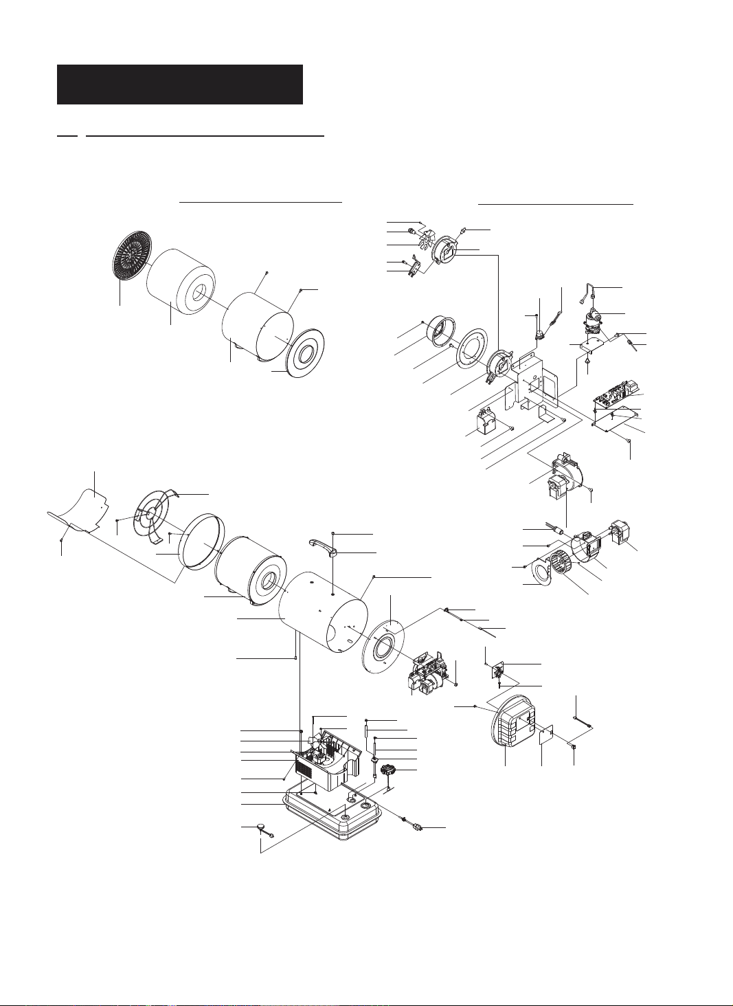
13. EXPLODED PARTS DRAWING
NOTE : SPECIFY MODEL NUMBER AND PART NUMBER WHEN ORDERING PARTS.
42
41
23-4
28
CHAMBER FULL ASSEMBLY
23-3
23-1
23-2
27
26
25
23
16
24
11
14
12
11
17
9
1
2
23-5
13
15
1-7
1-3
1-6
1-5
1-4
29-4
40
39
29-5
18
29-3
29-2
29
5
BURNER FULL ASSEMBLY
1-2
1-1
29-26
29-24
29-25
29-17
29-20
29-1
29-6
29-13
29-14
29-11
29-12
29-15
29-16
15-6
15-3
20
36
15-8
21
15-7
22
35
37
34
33
3231
19
30
38
6
5
4
3
7
10
15-4
15-1
15-5
29-22
29-19
29-8
15-2
29-18
29-21
29-23
29-10
29-9
29-7
12

NEVER LEAVE THE HEATER
UNATTENDED WHILE BURNING!
14. PARTS LIST
KEY NO. DESCRIPTION
1
2
3
4
5
6
7
8
9
10
11
12
13
14
15
16
17
18
19
20
21
22
23
23-1
23-2
23-3
23-4
23-5
24
25
26
27
28
29
29-1
1-1
1-2
1-3
1-4
1-5
1-6
1-7
29-2
29-3
29-4
29-5
Fuel Tank Assembly
Gauge Fuel Assembly
Filter Fuel Assembly
Line-Fuel
Clamp-Line
Line-Fuel Return
Cap-Fuel
Shell Supportor
Nut-Wing
Power Cord
Nut
Cooling Motor
Bolt-RH
Cooling Fan
Spring
Shell
Flange Screw
Shell Insulator Assembly
Screw-TH1
Thermostat Limit
Screw-RH2S
Limit Wire
Chamber Full Assembly
Chamber Assembly
Chamber Insulator
Ceramic Fiber
Heat Plate
Screw-TH1
Screw-TH1
Shell Ring
Screw-TH1
Safety Guard Assembly
Screw-TH2S
Burner Full Assembly
Burner Body Assembly
Burner Body
Nipple
Nozzle
Spark Plug
Bolt-HEX
Burner Blade
Bolt-PH
Insulator Plate
Bolt-TH
Diffusion Cap
Screw-RH2S
PART NO.
SF70DGD
2151-0056-01
2156-0066-00
2155-0017-00
3341-0027-00
3730-0040-00
3341-0045-00
2151-0041-00
3221-0089-00
4339-0012-00
3980-0287-00
4331-0028-00
3970-0272-00
4321-0246-00
3221-0090-00
3431-0053-00
3111-0418-03
4319-0015-03
2152-0209-00
4311-0040-00
38C0-0144-00
4312-0199-00
39D0-0998-00
2152-0173-00
2152-0208-00
3121-0673-00
3331-0069-00
3121-0674-00
4311-0040-00
4311-0044-00
3121-0676-01
4311-0044-00
2153-0035-01
4312-0040-00
2152-0301-00
2152-0211-00
3531-0031-00
3541-0111-00
3740-0120-00
3631-0027-00
4321-0230-00
3131-0584-00
4321-0231-00
3121-0677-00
4321-0216-00
3121-0626-00
4312-0200-00
Quantity
1
1
1
1
2
1
1
1
4
1
4
1
4
1
1
1
4
1
4
1
2
1
1
1
1
1
1
8
3
1
2
1
3
1
1
1
1
1
1
1
1
1
1
3
1
3
13
NEVER LEAVE THE HEATER
UNATTENDED WHILE BURNING!
14. PARTS LIST
KEY NO. DESCRIPTION
29-6
29-7
29-8
29-9
29-10
29-11
29-12
29-13
29-14
29-15
15-1
15-2
15-3
15-4
15-5
15-6
15-7
15-8
29-16
29-17
29-18
29-19
29-20
29-21
29-22
29-23
29-24
29-25
29-26
30
31
32
33
34
35
36
37
38
39
40
41
42
Burner Supporter
PCB Supporter
Screw-TH1
Card-Supporter
Spacer-Supporter
Motor Supporter
Screw-TH1
Ignitor
Screw-TH1
Blower Motor Assembly
Blower Body
Blower Motor
Bolt-TH
Blower Fan Assembly
Set Screw
Photocell
Blower Cover
Screw-TH2S
Bolt-TH
Pump Supporter
Sccrew-TH1
Electronic Pump
Bolt-TH
Wire-Pump
Fuel Pipe
Control PCB Assembly
Vibration Switch
Screw-RH2S
Vibration Switch Wire
Nut-HEX2
Back Cover
Inlay
Operating Switch
Wire-Operating Switch
Display PCB Assembly
Screw-RH2S
Wire-Display 3P
Screw-TH1
Handle
Bolt-TH
Heat Shield
Bolt-TH
PART NO.
SF70DGD
3131-0585-00
3131-0628-00
4311-0040-00
3713-0016-00
3713-0004-00
3131-0629-00
4311-0040-00
39E0-0076-00
4311-0040-00
2154-0157-00
3221-0091-00
3970-0273-00
4321-0232-00
2154-0104-00
4323-0007-00
2153-0029-00
3221-0092-00
4312-0198-00
4321-0233-00
3131-0587-00
4311-0040-00
3970-0274-00
4321-0247-00
39D0-0996-00
3740-0107-00
215A-0093-00
39A0-0050-00
4312-0199-00
39D0-0810-00
4331-0028-00
3211-0031-00
3221-0107-02
39A0-0191-00
39D0-0809-00
215A-0094-00
4312-0199-00
39D0-0997-00
4311-0044-00
3231-0073-00
4321-0117-00
3121-0789-01
4321-0117-00
Quantity
1
1
2
2
4
1
2
1
2
1
1
1
3
1
1
1
1
2
3
1
2
1
2
1
1
1
1
2
1
3
1
1
1
1
1
1
1
4
1
2
1
2
14
 Loading...