

Dyna-Glo RMC-FA300DGD User Manual
Operating Instructions & Parts Manual RMC-FA300DGD
Please read and save these instructions. Read carefully before attempting to assemble, install, operate or maintain the product described. Protect yourself and
others by observing all safety information. Failure to comply with instructions could result in personal injury and/or property damage! Retain instructions for
future reference.
TM
Dyna-Glo
Delux
Propane Construction Heater
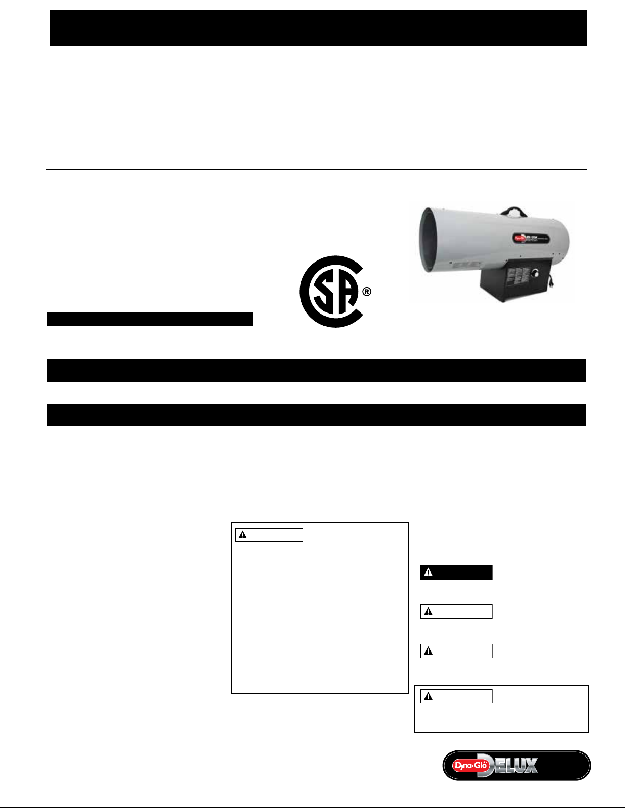
Description
Dyna-GloTM Delux Model RMC-FA300DGD heaters are 300,000 BTU/Hr construction
heaters. This heater uses propane gas for combustion, and electricity to run the
fan. It is primarily intended for temporary heating of well-ventilated buildings
under construction, alteration or repair. This heater should be utilized in sheltered,
well-ventilated areas, but never in occupied dwellings.
Specifications
Electrical Specifications
Model Electrical Input Amperage
RMC-FA300DGD 120 V, 60 Hz 0.65
ANS Z83.7-2011 CSA 2.14-2011 Construction Heater
C US
General Specifications
Output Rating Maximum Fuel Regulator
Model BTU/Hr Fuel Consumption Ignition Outlet Pressure
RMC-FA300DGD 300,000 Propane Vapor Only 13.9 lb/h Direct Spark, Interrupted 7-10 PSIG
Hot Air Output Minimum Supply Maximum Supply Size
Model Approx. (CFM) Motor Pressure to Regulator Pressure to Regulator L x W x H (Inches) RMC-RMC-
RMC-FA300DGD
FA300DGD 1800 0.085 HP 25 PSIG (For purposes Max Bottle Pressure 33.7 x 12.6 x 18.5
1,720 RPM of input adjustment)
(6.3 kg/h)
Figure 1 - Model RMC-FA300DGD
(85.6 x 32 x 47 cm)
Table of Contents Page
Description .......................1
Specifications......................1
Unpacking ....................... 1
General Safety Information ........1-3
Theory of Operation................3
Installation......................3-4
Ventilation........................4
Operation ......................4-5
Maintenance ....................5-6
Storage ..........................6
Wiring Diagram....................6
Repair Parts Illustration
and Parts List ....................7-8
Troubleshooting Chart ..............9
Warranty ........................11
Unpacking
1. Unpack all materials used to protect
the heater inside of carton. Retain
plastic caps attached to exposed
fittings for use during storage.
www.ghpgroupinc.com
2. Remove heater, accessories and all
hardware from carton.
3. Inspect all items for damage that may
have occurred during shipment.
WARNING
COMPLY WITH THE PRECAUTIONS AND
INSTRUCTIONS PROVIDED WITH THIS
HEATER, CAN RESULT IN DEATH, SERIOUS
BODILY INJURY AND PROPERTY LOSS,
OR DAMAGE FROM THE HZARARDS OF
FIRE, EXPLOSION, BURN. ASPHYXIATION,
CARBON MONOXIDE POISONING, AND/
OR ELECTRIC SHOCK.
ONLY PERSONS WHO CAN UNDERSTAND
AND FOLLOW THE INSTRUCTIONS
SHOULD USE OR SERVICE THIS HEATER.
IF YOU NEED ASSISTANCE OR HEATER
INFORMATION SUCH AS AN INSTRUCTION
MANUAL, LABELS, ETCETERA, CONTACT
THE MANUFACTURER.
GENERAL HAZARD
WARNING
FAILURE TO
General Safety Information
IMPORTANT: Be sure to read and
understand all cautions and warnings,
Printed in China
before operating this heater. Keep
this instruction manual for future
reference, and use it as a guide to safe
and proper operation of the heater.
Various precautions appear throughout
this manual. Please review and pay
close attention to them. Below is an
explanation of the various levels of
caution required while operating this
heater.
DANGER
which, if not avoided, WILL result in death
or serious injury.
WARNING
which, if not avoided, COULD result in
death or serious injury.
CAUTION
which, if not avoided, MAY result in minor
or moderate injury.
WARNING
EXPLOSION HAZARD, KEEP SOLID
COMBUSTIBLES, SUCH AS BUILDING
Indicates an im minen tly
hazardous situation
Indicates a poten tially
hazardous situation
Indicates a poten tially
hazardous situa tion
FIRE, BURN,
INHALATION, AND
PROFESSIONAL GRADE
IMLPF300DGD - HBC
Dyna-GloTM Delux Operating Instructions and Parts Manual
RMC-FA300DGD
Dyna-Glo
TM
Propane Construction Heater
NEVER LEAVE THE HEATER
UNATTENDED WHILE BURNING!
MATERIALS, PAPER OR CARDBOARD, A SAFE
DISTANCE AWAY FROM THE HEATER AS
RECOMMENDED BY THE INSTRUCTIONS.
NEVER USE THE HEATER IN SPACES WHICH
DO OR MAY CONTAIN VOLATILE OR
AIRBORNE COMBUSTIBLES, OR PRODUCTS
SUCH AS GASOLINE, SOLVENTS, PAINT
THINNERS, DUST PARTICLES OR UNKNOWN
CHEMICALS.
California Proposition 65 Warning:
Fuels used in gas or oil fired appliances
and the products of combustion of such
fuels, contain chemicals known to the
State of California to cause cancer, birth
defects or other reproductive harm. This
product contains chemicals, including lead
and lead compounds, known to the state
of California to cause cancer, birth defects
or other reproductive harm. Wash hands
after handling.
WARNING
requires that the heater is positioned
so that it is protected against any possible
damage by a moving vehicle, etc. It must be
positioned so that the base of the heater is
no less than 18 in (450 mm) above the
garage floor or 8 ft (2450 mm) in repair
garages. The heater must be placed on a
stable surface. Do not place it on a chair,
ladder, etc. Raising the heater will reduce
BUT NOT eliminate the possibility of lighting
the vapor of any flammable liquids which
may be improperly stored or accidentally
spilled. If the smell of gasoline is present,
DO NOT operate this heater until the area
has been properly ventilated.
WARNING
The heater is designed and approved
for use as a construction heater
under ANS Z83.7 CSA 2.14. It is hard
to anticipate every use which may
be made of this heater. CHECK WITH
YOUR LOCAL FIRE SAFETY AUTHORITY
IF YOU HAVE QUESTIONS ABOUT
APPLICATIONS.
Other standards govern the use of fuel
gases and heat producing products in
Using this heater in a
residential garage
Not for home or recreational vehicle use.
specific applications.
Your local authority can advise you
about these.
IMPORTANT: READ THIS USER’S
MANUAL CAREFULLY AND
COMPLETELY BEFORE TRYING TO
OPERATE OR SERVICE THIS HEATER.
IMPROPER USE OF THIS HEATER CAN
CAUSE SERIOUS INJURY OR DEATH
FROM FIRE, EXPLOSION AND CARBON
MONOXIDE POISONING.
This is a direct-fired forced air
construction heater for either indoor
construction or outdoor use. Its
intended use is primarily the temporary
heating of buildings or structures under
construction, alteration or repair. All
the products of combustion generated
by the heater are forced through the
heater and released into the area
being heated. This heater operates
at approximately 98%+ combustion
efficiency but still produces a small
amount of carbon monoxide. Humans
can tolerate small amounts of carbon
monoxide for short periods. Carbon
monoxide can build up in a heated
space and failure to provide adequate
ventilation could result in poisoning or
death.
CSA 2.14b-2009, ANS Z83.7b-2009.
IMPORTANT SAFETY INFORMATION
• Children should be carefully
supervised, when they are in the area.
• Always maintain proper clearance
from combustible materials. Minimum
clearance from combustibles:
Side - 24” (61cm); Top - 72” (1.8 m);
Front - 96” (2.4 m). Floor - combustible.
Not for use on finished floors.
• Heater must be placed on level and
stable surface.
• Never place anything including clothes
or other flammable items on the heater.
• The appliance area shall be kept clear
and free from combustible materials,
gasoline and other flammable
vapours and liquids.
• Do not modify or operate a heater
which has been modified.
• Adequate clearance for accessibility
and for combustion & ventilation air
supply must be maintained at all
times when the heater is operating.
• Service and repair should be done by
a qualified service person. The heater
should be inspected before each use
and at least annually by a qualified
person. More frequent cleaning may
be required as necessary. Do not service
while hot or operating.
• Never connect heater to an
unregulated gas supply.
• The heater is shipped from the
factory for LP(Propane) gas. This heater
is for use with propane gas only, do
not convert heater to any other gas.
Installation must conform to local
codes or, in the absence of local codes,
with the standard for the Storage and
Handling of Liquefied Petroleum Gases
ANSI/NFPA 58 and the Natural Gas and
Propane Installation Code CSA B149.1
• The minimum and maximum inlet
pressures to the regulator from the
gas tank are 5 psi and bottle pressure,
respectively. Use only the regulator
& hose assembly provided with the
heater. Inspect the regulator/hose
assembly prior to each use of the
heater. If there is excessive abrasion
or wear, or hose is cut, replace with
regulator/hose assembly listed on the
parts list prior to using this heater.
For Technical Support or Troubleshooting, Call: 1-877-447-4768, 8:30 am - 4:30 pm CST www.ghpgroupinc.com
2
Dyna-Glo
TM
Delux Operating Instructions and Parts Manual
Models RMC-FA300DGD
NEVER LEAVE THE HEATER
UNATTENDED WHILE BURNING!
• Gas supply connections should be
checked using a 50/50 solution of liquid
dish soap and never use a flame to
check for gas leaks.
• The electrical connection & grounding
must comply with National Electrical
Code. ANSI/NFPA 70 or in Canada CSA
C22.1, Canadian Electrical Code, Part 1.
Use only a properly grounded three (3)
prong receptacle.
• Do not restrict inlet or outlet by any
means. The flow of combustion and
ventilation air is not to be obstructed.
• This heater should not be directed
toward any propane-gas container
within 20 ft (6 m). The heater must be
located at least 6 ft. (1.83 m) in the U.S.;
or (ii) 10 ft. (3 m) in Canada, from any
propane gas container.
• The propane cylinder supply system
must be arranged to provide for vapour
withdrawal from the operating cylinder.
• This heater is not to be used with
external thermostats, timers or other
devices that control or alter electrical
supply to the heater.
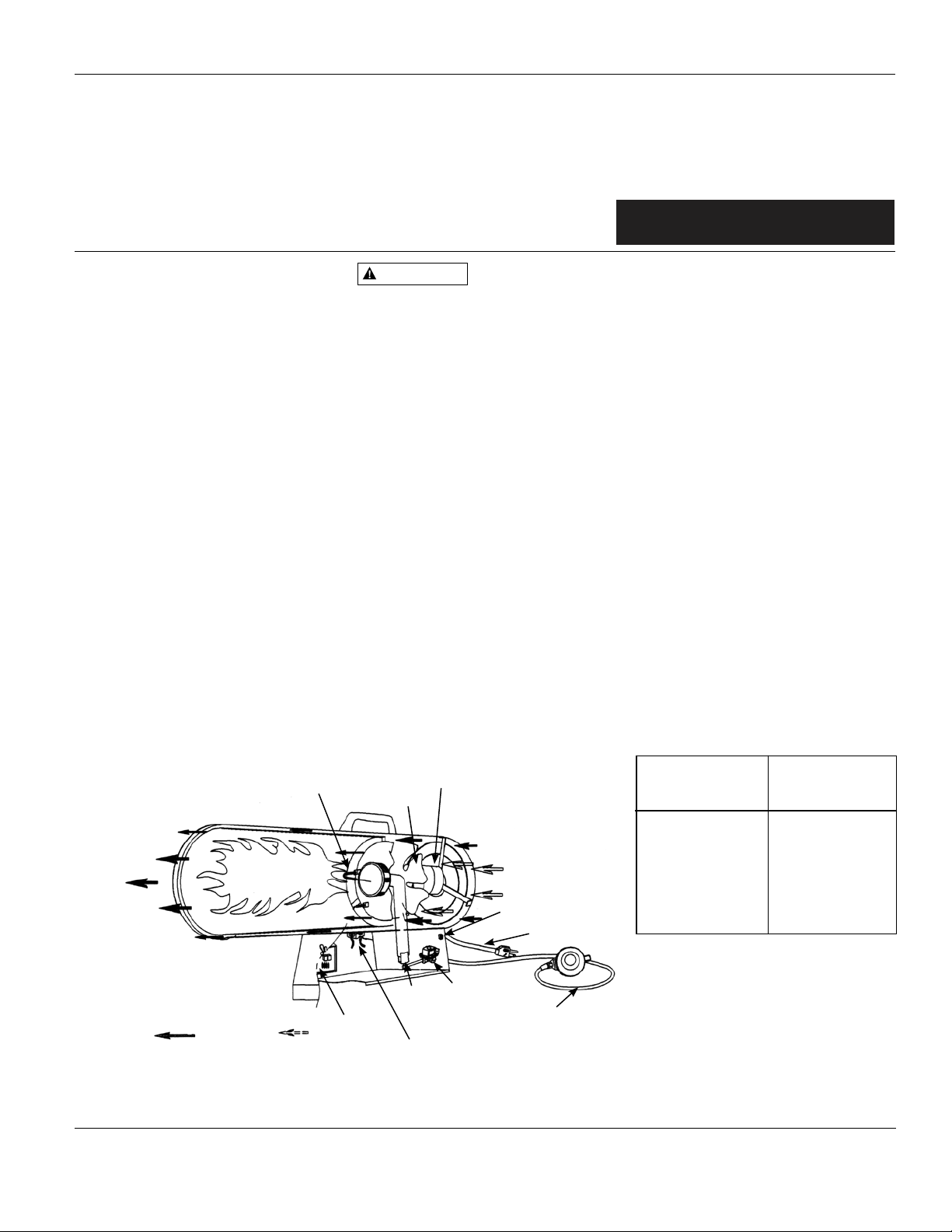
Ignitor
Clean Heated
Air Out (Front)
Combustion Chamber
PCB Control
Air For Heating Air For Combustion
Figure 2 – Cross Section Operational View
WARNING
during operation and at shutdown, in order
to prevent a flame-out condition which
could result in personal injury or property
damage.
Motor and fan must be
running before lighting,
• Do not adjust regulator below 7 PSIG
or above 10 PSIG
Theory of Operation
FUEL SYSTEM
The hose/regulator assembly runs from
the propane supply to the heater itself.
After the gas runs through the hose
and regulator, it passes through the
solenoid valve and out the nozzle into
the combustion chamber.
AIR SYSTEM
The internal motor turns the fan, which
pushes air around and through the
combustion chamber. Here the air is
heated and provides a constant stream
of warmth.
IGNITION SYSTEM
The spark module sends voltage to the
ignitor. The ignitor ignites the fuel and
air mixture.
Motor
Fan
Cool Air In (Back)
On/Off Switch
Power Cord
Nozzle
Solenoid Valve
Hose / Regulator
Assembly
Spark Module (Spark Ignitor)
SAFETY CONTROL SYSTEM
This system shuts the heater down
if the flame is extinguished. The fan
and motor will continue to operate,
butthere will not be any heat.
PROPANE SUPPLY
All propane gas and tanks are to be
provided by the user.
This heater should only be used with
a tank that has a vapor withdrawal
system. Refer to the Standard of
Storage and Handling of Liquefied
Petroleum Gas, ANSI/NFPA 58, Chapter
5. Your local fire department or library
will have this information.
Two factors will dictate how much
propane is used from each tank:
1. The amount of gas in each tank.
2. The surrounding air temperature at
each tank.
The chart below shows how many tanks
should be used at a given tempera ture.
This heater should not be operated with
a tank smaller than 100 pounds.
As the tempera ture drops, less gas is
Average
Temperature
at Tank Location
°F
40
32
40
20
32
10
20
0
10
-10
0
-20
-10
-20
°C
4.44
0
-6.67
-12.22
-17.78
-23.33
-28.89
Number
of Tanks
3
Use larger tank
Use larger tank
Use larger tank
Use larger tank
Use larger tank
Use larger tank
Use larger tank
vaporized, so a larger tank may be
necessary in very cold weather. Never
operate this heater with a tank smaller
than 100 pounds. Your local propane
dealer can help you select the proper
tank size and configuration.
For Technical Support or Troubleshooting, Call: 1-877-447-4768, 8:30 am - 4:30 pm CST www.ghpgroupinc.com
3
supplied with the heater.
ProFitter
TM
& Dyna-GloTMOperating Instructions and Parts Manual
ProFitterTM& Dyna-Glo
TM
RMC-FA300PF/DG/DGD
Dyna-GloTM Delux Operating Instructions and Parts Manual
RMC-FA300DGD
Dyna-Glo
TM
Propane Construction Heater
NEVER LEAVE THE HEATER
UNATTENDED WHILE BURNING!
Installation
Installation
warnings in the Safety Information
warnings in the Safety Information
Section on pages 1–3. They are required to
Section on pages 1–3. They are required
operate this heater safely. Follow all local
to operate this heater safely. Follow all
and state codes when operating this
local and state codes when operating
heater.
this heater.
making the proper connections, be sure
making the proper connections, be sure
to check for leaks. Apply a 50/50
to check for leaks. Apply a 50/50
mix ture of dish soap and water to
mixture of dish soap and water to
all connections. Bubbles forming are
all connections. Bubbles forming are
evidence of a leak. Be sure to correct
evidence of a leak. Be sure to correct
all leaks at once!
all leaks at once!
1. Provide propane supply system as
1. Provide propane supply system as
outlined above.
outlined above.
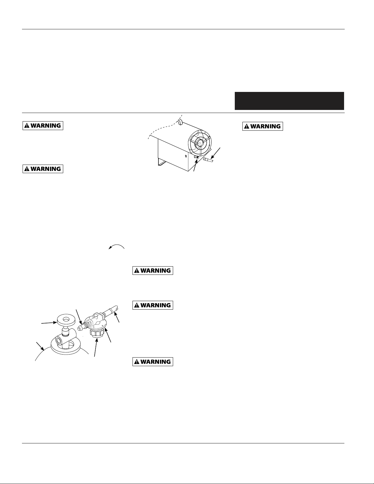
2. Connect POL fitting on hose/regulator
2. Connect POL fitting on hose/regulator
assembly to propane tank(s) by turn ing
assembly to propane tank(s) by turn-
the fitting COUNTER CLOCKWISE
ing the fitting COUNTERCLOCKWISE
into the threads on the valve on top of
into the threads on the valve on top
the tank. Finish by tightening firmly,
of the tank. Finish by tightening
using 7/8” (22.2 mm) wrench.
firmly, using 7/8” wrench.
IMPORTANT: To protect the regulator
IMPORTANT: To protect the regulator
from weather damage, tighten the
from weather damage, tighten the
fitting with the black adjustment knob
fitting with the black adjustment knob
pointing down.
pointing down.
POL Fitting
POL Fitting
Supply
Supply
Valve
Valve
Propane/LP
Propane/LP
Tank
Tank
Figure 3 – Regulator with Vent Pointing
Figure 3 – Regulator with Vent Pointing
3. Connect female end of hose to the
3. Connect female end of hose to the
inlet connector of the heater, and
inlet connector of the heater, and
tighten firmly with a wrench.
tighten firmly with a wrench.
IMPORTANT: Use extra piping or hose
IMPORTANT: Use extr
if necessary to connect the heater to the
if necessary to connect the heater to the
gas supply, but always use the regulator
gas supply, but always use the regulator
supplied with the heater.
For Technical Support or Troubleshooting, Call: 1-877-447-4768, 8:30 am - 4:30 pm CST www.ghpgroupinc.com
Down
Down
Review and under-
Review and under-
stand all of the
stand all of the
After installing
After installing
all gas piping, and
all gas piping, and
Regulator
Regulator
Adjustment Knob
Adjustment Knob
(Pointing Down)
(Pointing Down)
a piping or hose
Hose
Hose
Inlet Connector
Inlet Connector
Figure 4 – Hose and Inlet Connector
Figure 4 – Hose and Inlet Connector
4. Open supply valve on propane tank(s)
4. Open supply valve on propane tank(s)
SLOWLY.
SLOWLY.
NOTE: If this valve is not opened slowly,
NOTE: If this valve is not opened slowly,
the excess flow check valve on the tank
the excess flow check valve on the
will interrupt the gas flow. If this
tank will interrupt the gas flow. If this
happens, close the supply valve and
happens, close the supply valve and
reopen slowly.
reopen slowly.
5. Adjust the regulator to between 7
5. Adjust the regulator to between 7
and 10 PSIG.
and 10 PSIG.
PSIG or below 7 PSIG, or the heater may
PSIG or below 7 PSIG, or the heater may
not operate properly.
not operate properly.
6. Check all connections for leaks.
6. Check all connections for leaks.
leaks. Apply a 50/50 solution of liquid
leaks. Apply a 50/50 solution of liquid
dish soap a
dish soap and water to check all
connections. Correct all leaks
connections. Correct all leaks
immediately.
immediately.
7. Close propane supply valve.
7. Close propane supply valv
nd water to check all
Do not adjust the
Do not adjust the
regulator above 10
regulator above 10
Never use an open
Never use an open
flame to check for
flame to check for
e.
Ventilation
Ventilation
ventilation requirements. If these
ventilation requirements. If these
guidelines are not followed, carbon
guidelines are not followed, carbon
monoxide poisoning can occur. Always
monoxide poisoning can occur. Always
provide proper amounts of fresh air
provide proper amounts of fresh air
before operating this heater.
before operating this heater.
Provide at least three square feet of
Provide at least three square feet (0.28 m²)
fresh, outside air for each 100,000
of fresh, outside air for each 100,000 BTU/
BTU/Hr of rating. This heater requires
Hr of rating. This heater requires
a fresh air opening of at least 11.25
a fresh air opening of at least 11.25 square
squ
are feet. Provide extra fresh air if
feet (1.05 m²). Provide extra fresh air if
more heaters are being used.
more heaters are being used.
Always follow the
Always follow the
minimum fresh air
minimum fresh air
Hose
Hose
Operation
Operation
warnings in the Safety Information
warnings in the Safety Information
Section, on pages 1–3. They are required
Section, on pages 1–3. They are required
to operate this heater safely. Follow all
to operate this heater safely. Follow all
local and state codes when operating this
local and state codes when operating
heater.
this heater.
TO START HEATER
TO START HEATER
1. Follow all safety, installation and
1. Follow all safety, installation and
ventilation instructions in this
ventilation instructions in this
manual.
manual.
2. Position the heater on a stable and
2. Position the heater on a stable and
level surface, and be sure that no
level surface, and be sure that no
drafts blow into the inlet or outlet
drafts blow into the inlet or out
of the heater.
of the heater.
3. Plug the power cord of the heater
3. Plug the power cord of the heater
into a three hole grounded extension
into a three hole grounded extension
cord. Be sure that the extension cord
cord. Be sure that the extension cord
is at least 6 feet long, and is UL listed.
is at least 6 feet long, and is UL listed.
EXTENSION CORD SIZE
EXTENSION CORD SIZE
REQUIREMENT
REQUIREMENT
• Up to 50 feet (15.2 m) long, use 18
• Up to 50 feet long, use 18 AWG
AWG rated cord.
rated cord.
• 51 to 100 feet (15.5 - 30.5 m) long,
• 51 to 100 feet long, use 16 AWG
use 16 AWG rated cord.
rated cord.
• 101 to 200 feet (130.8 - 61 m) long,
• 101 to 200 feet long, use 14 AWG
use 14 AWG rated cord.
rated cord.
4. Plug extension cord into a 120 volt/60
4. Plug extension cord into a 120 volt/60
hertz, three hole grounded outlet.
hertz, three hole grounded outlet.
5. Open supply valve on propane tank(s)
5. Open supply valve on propane tank(s)
SLOWLY.
SLOWLY.
NOTE: If this valve is not opened slowly,
NOTE: If this valve is not ope
the excess flow check valve on the
the excess flow check valve on the tank
tank will interrupt the gas flow. If this
will interrupt the gas flow. If this
happens, close the supply valve and
happens, close the supply valve and
reopen slowly.
reopen slowly.
6. Adjust the regulator to between 7
6. Adjust the regulator to between 7
and 10 PSIG.
and 10 PSIG.
NOTE: The higher regulator setting
NOTE: The higher regulator setting
will enable the heater to produce
will enable the heater to produce
more heat.
more heat.
Review and under-
Review and under-
stand all of the
stand all of the
let
ned slowly,
4
 Loading...