

Dyna-Glo KFA650DGD User Manual
INDOOR/OUTDOOR PRODUCTS
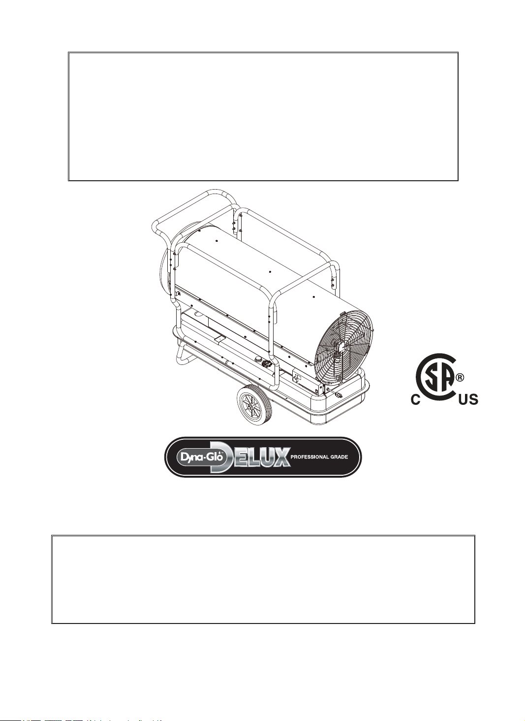
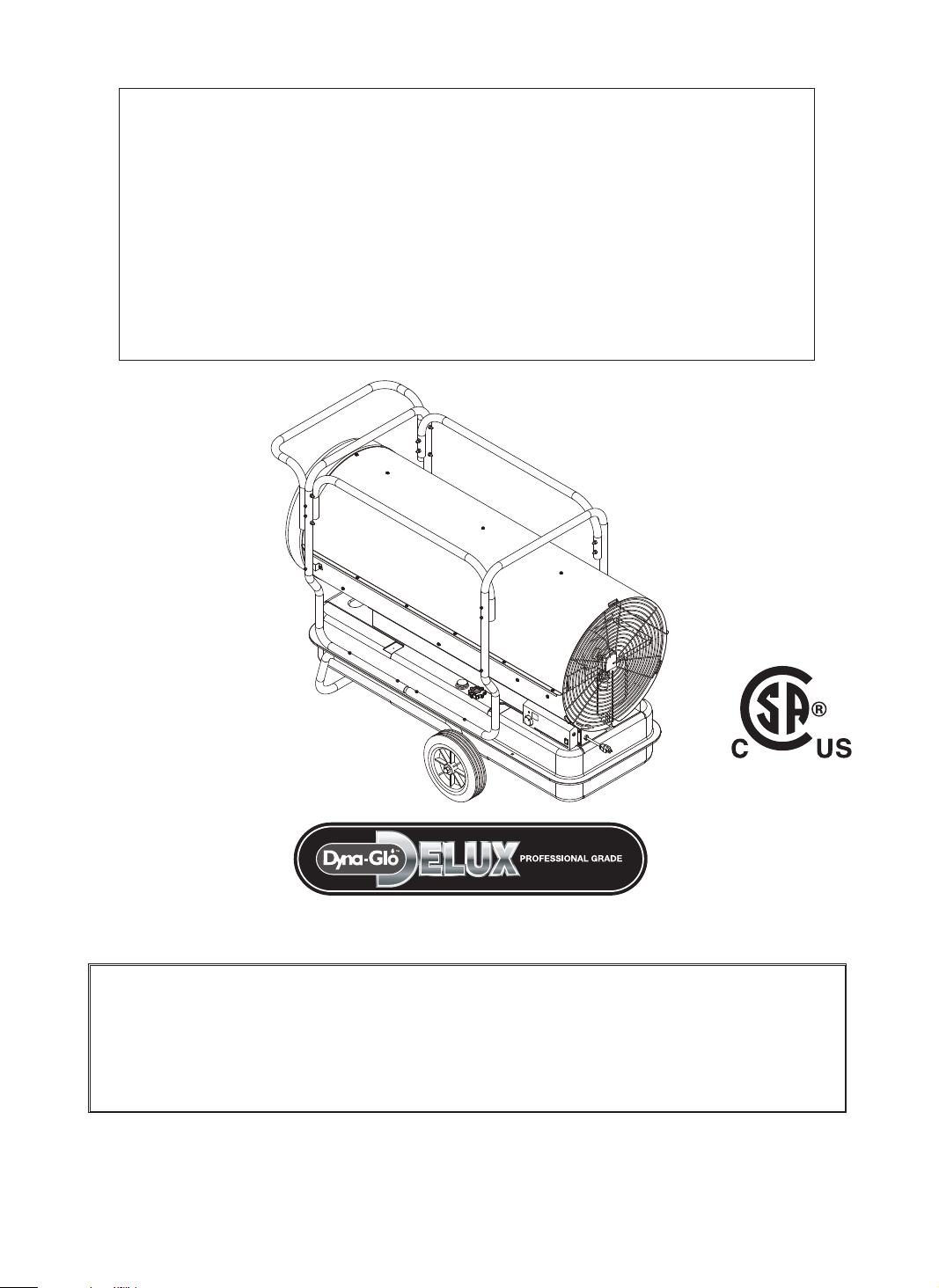
KEROSENE PORTABLE
FORCED AIR HEATERS
“USER’S MANUAL AND
OPERATING INSTRUCTIONS”
COMPLIES WITH
ANSI A10.10-1998
CAN/CSA/B140.0-03 AND CSA
B140.8-1967
MODEL : KFA650DGD
Before the first use of this heater, please read this USER’S MANUAL very
carefully. This USER’S MANUAL has been designed to instruct you as to
the proper manner in which to assemble, maintain, store, and most
importantly, how to operate the heater in a safe and efficient manner.
Please keep this manual for future reference.
CONSUMER : Retain this manual for future reference.
Questions, problems, missing parts? Before returning to your retailer, call our customer
service department at 877-447-4768 8:30 a.m. - 4:30 pm CST, Monday - Friday.
or email us at customerservice@ghpgroupinc.com
IMKFA650DG-KDS
NEVER LEAVE THE HEATER
UNATTENDED WHILE BURNING!
DANGER: IMPROPER USE OF THIS HEATER CAN RESULT IN SERIOUS INJURY OR DEATH
FROM BURNS, FIRE, EXPLOSION, ELECTRICAL SHOCK AND/OR CARBON
MONOXIDE POISONING.
WARNINGS:
1. RISK OF INDOOR AIR POLLUTION!
• Use this heater only in well ventilated areas. Provide at least a three-square foot (2,800 sq. cm.)
opening of fresh outside air for each 100,000 BTU/hr. of heater rating.
• People with breathing problems should consult a physician before using the heater.
• Carbon monoxide poisoning: headaches, dizziness
and/or nausea. If you have these signs, the heater may not be working properly.
Get fresh air at once! Have the heater serviced. Some people are more affected by carbon monoxide than others.
These include pregnant women, persons with heart or lung diseas
those at high altitudes.
• Never use this heater in living or sleeping areas.
2. RISK OF BURNS / FIRE / EXPLOSION!
• NEVER use any fuel other than 1-K kerosene, #1/#2 disel/fuel oil, JET A or JP-8 fuels in this heater.
• NEVER use use fuel such as gasoline, benzene, paint thinners or other oil compounds in this heater.
(RISK OF FIRE OR EXPLOSION)
• NEVER
• NEVER ill hot.
CAUTION:
Hot while in operation. Do not touch. Keep children,
clothing and combustibles away from heater.
Minimum Clearances: Outlet: 8 feet (250cm) / Sides, top and rear: 4 feet (125cm)
• NEVER block air inlet (rear) or air outlet (front) of heater.
• NEVER use duct work in front or behind of heater.
• NEVER move or handle heater while it is hot, operating, or plugged in.
• NEVER transport heater with fuel in it’s tank.
• When used with an optional thermostat or if equipped with a thermostat, heater may start at any time.
• ALWAYS locate heater on a stable and level surface.
• ALWAYS keep children and animals away from heater.
• Bulk fuel storage should be a minimum of 25 ft. from heaters, torches, portable generators or other sources of ignition.
All fuel storage should be in accordance with federal, state or local authorities having jurisdiction.
3. RISK OF ELECTRIC SHOCK!
•
• Use only a three-prong, grounded outlet and extension cord.
• ALWAYS install the heater so that it is not directly exposed to water spray, rain, dripping water or wind.
• ALWAYS unplug the heater when not in use.
on the model plate of the heater.
WARNING: This product and the fuel used to operate this product (kerosene or other
approved fuels), and the products of combustion of such fuel, can expose you to chemicals including
benzene, which is known to the State of California to cause cancer and reproductive harm.
For more information go to www.p65Warnings.ca.gov
MASSACHUSETTS RESIDENTS: Massachusetts state law prohibits the use of this heater in any
building which is used in whole or in part for human habitation. Use of this heating device in
CANADIAN RESIDENTS: Use of this heater shall be in accordance with authorities having
jurisdiction and CSA Standard B139.
NEW YORK CITY RESIDENTS: For use only at construction sites in accordance with applicable NYC
1
NEVER LEAVE THE HEATER
UNATTENDED WHILE BURNING!
CONTENTS OF USER’S MANUAL
ITEM PAGE #
REPLACING FUSE10
EDIUG GNITOOHS ELBUORT11
14
15
16MARGAID GNIRIW12
17SNOITACIFICEPS13
18GNIWARD STRAP DEDOLPXE14
19TSIL STRAP15
1EDIUG YTEFAS - SNOITUACERP
2NOITCUDORTNI.1
2SERUTAEF.2
3YLBMESSA DNA GNIKCAPNU.3
4FUEL SELECTION .4
5NGISED RETAEH FO WEIVREVO.5
5RETAEH RUOY GNILEUF.6
6NOITAREPO.7
8RETAEH RUOY FO EGAROTS MRET GNOL.8
9ECNANETNIAM.9
1. INTRODUCTION
Please read this USER’S MANUAL carefully. It will show you how to assemble, maintain, and operate the
heater safely and efficiently to obtain full benefits from its many built-in features.
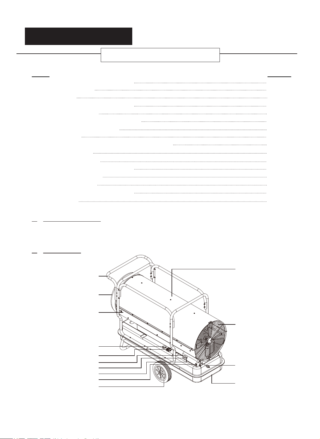
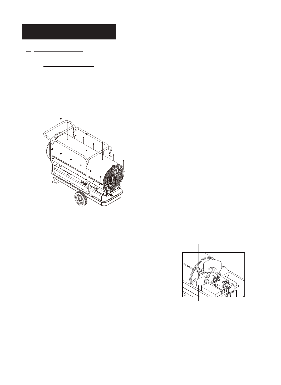
2. FEATURES
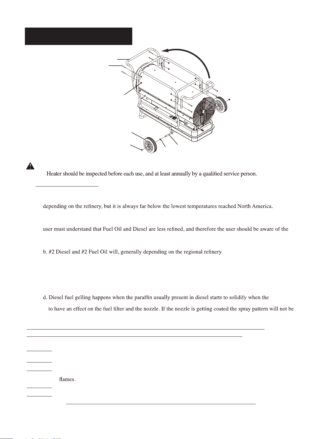
Upper Shell
Front Handle
Hot Air Outlet
Shell Lower
Fan Guard
Fuel Gauge
Fuel Cap
Thermostat Knob
Lamp
Room Temp. Display
Operating Switch
Wheel
Figure 1.KFA650DGD MODEL
Power Cord
Fuel Drain Bolt
2
3
NEVER LEAVE THE HEATER
UNATTENDED WHILE BURNING!
3. UNPACKING AND ASSEMBLY
1. REMOVE THE HEATER AND ALL PACKING MATERIALS FROM THE BOX. (See Fig.2)
NOTE: Save the shipping carton and packing materials for future storage.
Figure 2. PACKING MATERIALS
2. ASSEMBLING
Tools Required
Medium Phillips Screwdriver.
24 Socket Wrench.
Assembling wheel &handle
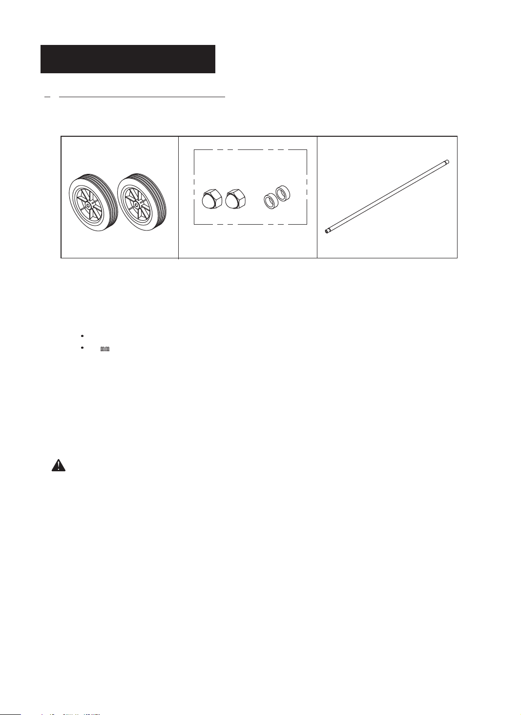
1. Slide threaded axle through the rear section of the wheel support frame.
2. Slide one axle bushing on to each side of the axle. Slide one wheel on to each side of the axle.
Attach one cap nut on to each side of the threaded axle and tighten well.
3. Loosen 4 screws on the front handle in order to remove handle front.
4. Move the removed handle front to the handle on the front side as Figure 5 and then tighten 4 screws
after matching handle and handle front.
CAUTION: DO NOT OPERATE heater without support frame assembled to tank.
Wheels
Cap Nuts Bushings Threaded Axle
Hardware Kit
HW-KFA1020
NEVER LEAVE THE HEATER
UNATTENDED WHILE BURNING!
Front Handle
Screw
Nut
Wheel
Cap Nut
Bushing
Axle
Figure 3. Assembling Handle & Wheel and Cord wrap
CAUTION: DO NOT OPERATE heater without support frame assembled to tank.
NOTE:
4. FUEL SELECTION
1. All models can use 7 different fuels: K1 Kerosene, #1 Fuel Oil, #1, Diesel, #2 Fuel Oil, #2 Diesel, Jet A, JP-8
2. K1 Kerosene is recommended for optimal combustion and performance, and for less maintenance. K1 is also
the optimal fuel choice in extremely low temperatures of 15°F or less, as its pour-point/"gel-point" varies
3. Jet A and JP-8 are also excellent choices for clean combustion, reduced maintenance, and temperatures below
15°F, but they are rarely found outside of the aviation industry or the military.
4. #1 Fuel Oil, #1 Diesel, #2 Fuel Oil, #2 Diesel are often selected, as they are readily available. However, the
following:
a. #1 Diesel and #1 Fuel Oil will have some degree of increased smoke/soot during ignition, increased smell,
and increased regular cleaning/maintenance.
use of #2 fuels will result in a little more smoke/soot during ignition, a greater increase in smell, and will
require more regular cleaning/maintenance than #1 fuels.
c. At temperatures lower than 15°F, most diesel/fuel oil blends will become more viscous (start to gel) as
the diesel falls below its pour point (starts to "gel"), and may pose a challenge igniting the heater and with
continuous operation of the heater. There are troubleshooting steps for this situation, but selecting K1 (or
JP-8/Jet A) is recommended when operating below 15°F. The colder the temperatures the more likely you
could problems you will experience diesel gelling.
temperature drops. At 32°F, the wax in liquid form will crystallize and leave the fuel clouded; this can start
correct which can cause white smoke and performance problems.
, burn dirtier than #1 fuels. The
KEROSENE SHOULD ONLY BE STORED IN A BLUE CONTAINER THAT IS CLEARLY
MARKED “KEROSENE”. NEVER STORE KEROSENE IN A RED CONTAINER.
Red containers are associated with gasoline.
NEVER store kerosene in the living space. Kerosene should be stored in a well ventilated place outside the
living area.
NEVER use any fuel other than 1-K kerosene (#1/#2 diesel/fuel oil, JET A or JP-8 fuels are acceptable substitutes)
NEVER use fuel such as gasoline, benzene, alcohol, white gas, camp stove fuel, paint thinners, or other oil
compounds in this heater. These are volatile fuels that can cause an explosion or uncontrolled
NEVER store kerosene in direct sunlight or near a source of heat.
NEVER use kerosene that has been stored from one season to the next. Kerosene deteriorates over time.
“OLD KEROSENE” WILL NOT BURN PROPERLY IN THIS HEATER.
4
NEVER LEAVE THE HEATER
UNATTENDED WHILE BURNING!
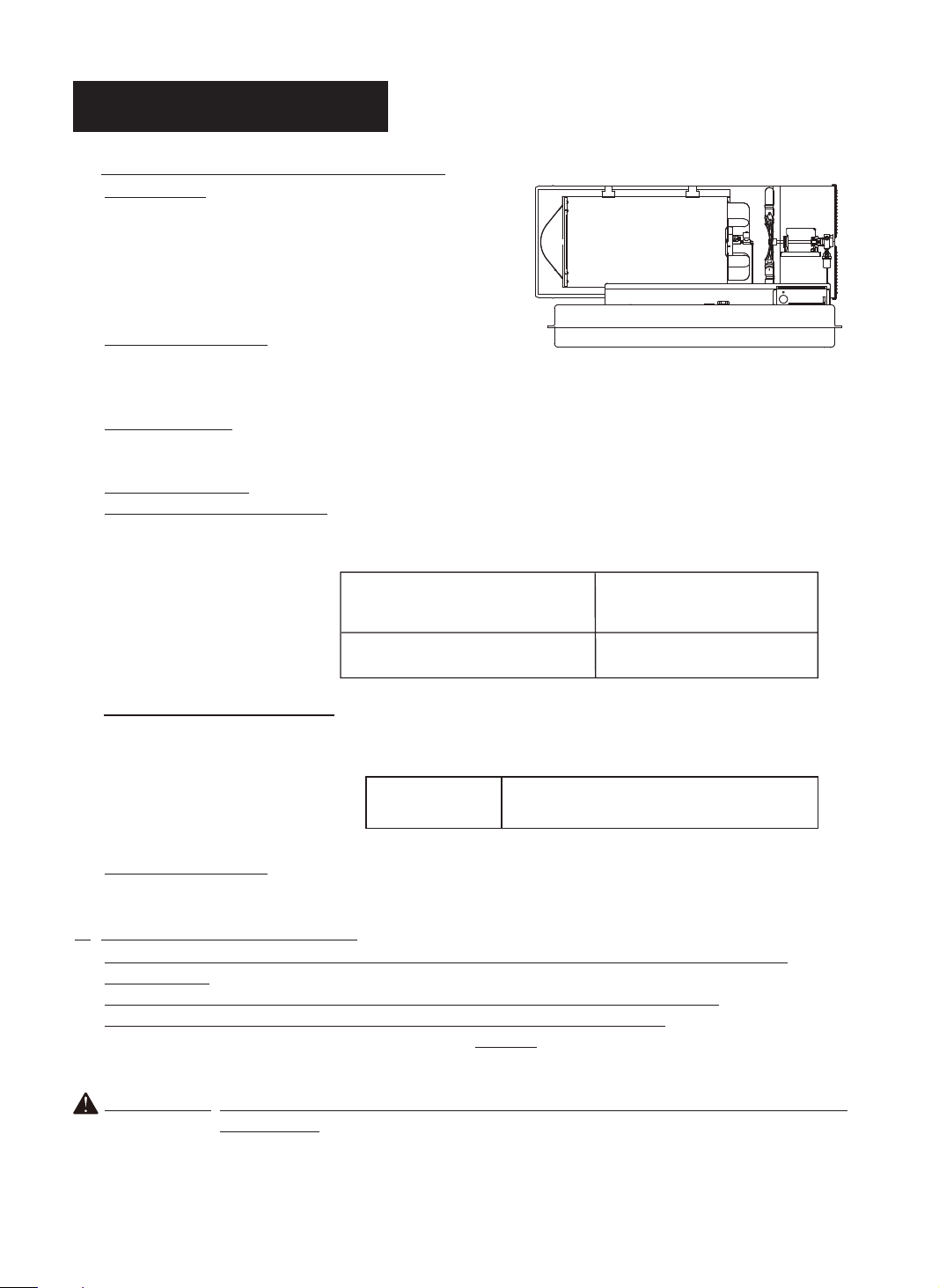
5. OVERVIEW OF HEATERS DESIGN
Fuel System: This heater is equipped with a Fuel
pump(Gear)that pulls fuel through the fuel line connected
to the fuel tank and then pushes fuel through a filter and a
solenoid valve and out the burner head nozzle.
This fuel is sprayed into the combustion chamber in a
fine mist.
“Sure Fire Ignition”: The electronic ignitor sends
voltage to a specially designed spark plug.
The spark plug ignites the fuel and air mixture.
The Air System: The heavy duty motor turns a fan that forces air into and around the
combustion chamber. This air is heated and then forced out the front of the heater.
The Safety System:
A. Temperature Limit Control: This heater is equipped with a Temperature Limit Control designed to
turn off the heater should the internal temperature rise to an unsafe level.
If this device activates and turns your heater off it may require service.
Internal Shut-Off Temp. Reset Temperature
Plus/Minus 10 Degrees Plus/Minus 10 Degrees
160˚F/71˚C 120˚F/49˚C
B. Electrical System Protection : This heaters electrical system is protected by a fuse mounted to the PCB
assembly that protects it and other electrical components from damage.
If your heater fails to operate check this fuse first and replace as needed.
FUSE TYPE:
C. Flame-Out Sensor : Utilizes a photocell to monitor the flame in burn chamber during normal operation.
It will cause the heater to shut-off should the burner flame extinguish.
250 VAC / 8 amps
6. FUELING YOUR HEATER
NEVER FILL THE HEATER FUEL TANK IN THE LIVING SPACE: FILL THE TANK
OUTDOORS.
DO NOT OVERFILL YOUR HEATER AND BE SURE HEATER IS LEVELED.
IMPORTANT NOTICE REGARDING FIRST IGNITION OF HEATER:
The first time you light the heater, it should be done outdoors. This allows the oils, etc. used in
manufacturing the heater to burn off outside.
WARNING!!: NEVER REFILL HEATER FUEL TANK WHEN HEATER IS OPERATING OR
STILL HOT.
5
NEVER LEAVE THE HEATER
UNATTENDED WHILE BURNING!
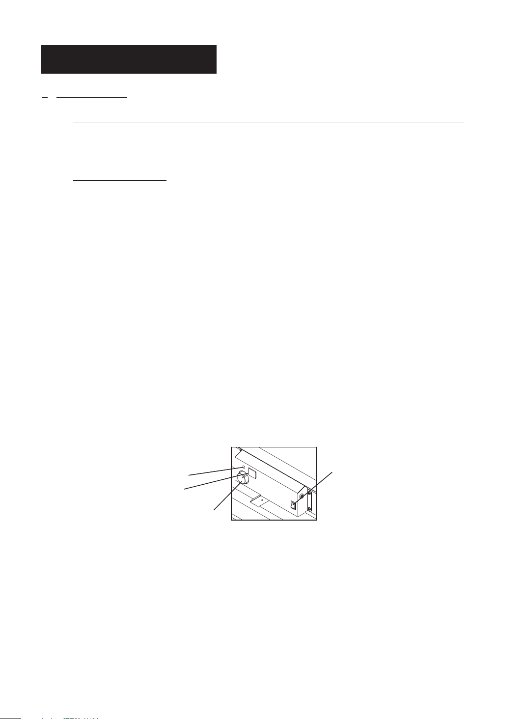
7. OPERATION
A.) VENTILATION
RISK OF INDOOR AIR POLLUTION/USE HEATER ONLY IN WELL VENTILATED AREAS.
Provide at least a three-square foot (2,800 sq. cm.) opening of fresh outside air for each 100,000 BTU/Hr.
of heater rating.
B.) OPERATION
TO START HEATER
1. Fill fuel tank with fuel.
NOTE : Kerosene is recommended when the temperature drops below 0℉ (-18℃) to prevent
ignition delay or failure.
2. Attach fuel cap.
3. Plug power cord of heater into three-prong, grounded extension cord.
Extension cord must be at least six feet long.
Extension Cord Wire Size Requirements
• 6 to 100 feet long, use 14 AWG conductor.
• 101 to 200 feet long, use 12 AWG conductor.
• 201 to 300 feet long, use 10 AWG conductor.
• 301 to 400 feet long, use 8 AWG conductor.
• 401 to 500 feet long, use 6 AWG conductor.
4.
Turn “Thermostat Control Knob” to desired setting (setting range : 40℉~110℉) and push
switch to “ON” position, power indicator lamp and room temp. display will light and heater will start.
NOTE: Room Temp. display indicates as following,
• When room temp. is less than 0℉ : “Lo”
• When room temp. is between 0℉and 99℉ : Indicates in figure.
• When room temp. is more than 99℉ : “Hi”
If heater does not start, the thermostat setting may be too low, turn “THERMOSTAT CONTROL
Knob” to higher position to start heater. If heater still does not start, turn operating switch to “OFF”
and then to “ON” position. (Figure 4). If heater still does not start, see Troubleshooting Guide on
page 13.
operating
INDICATOR LAMP
ROOM TEMP. DISPLAY
THERMOSTAT CONTROL KNOB
Figure 4. CONTROL PARTS
NOTICE : The major electrical components of this heater are protected by a safety fuse mounted to the PCB board.
If your heater fails to start, check this fuse first and replace as necessary. You should also check your
power source to insure that proper voltage and frequency are being supplied to the heater.
OPERATING SWITCH
6
7
NEVER LEAVE THE HEATER
UNATTENDED WHILE BURNING!
TO STOP HEATER
CAUTION ; Never unplug heater while heater is running
Heater must go through cooling cycle. The cooling cycle cools the
combustion chamber. Damage to heater can occur if combustion chamber
is not cooled. Do not restart heater until cooling cycle is complete.
1. Turn operating switch to “OFF”.
This will cause heater flame to go out.
The motor will continue to run during the cooling cycle.
(Room Temp. Display will show “CC” during the cooling cycle)
This allows the fan to cool the combustion chamber. When the cooling cycle
(approx.1Min) is finished, the motor will stop.
Do not unplug heater until cooling cycle is finished.
2. Unplug power cord.
3. To temporarily stop heaters, set thermostat at a temperature lower than air around heater,
Heater will cycle back on if air temperature around heater matches thermostat setting.
TO RESTART HEATER
CAUTION ; Do not restart heater until cooling cycle is finished.
The cooling cycle cools the combustion chamber.
1. Wait until cooling cycle is finished after stopping heater.
2. Repeat steps under to start HEATER.
8
NEVER LEAVE THE HEATER
UNATTENDED WHILE BURNING!
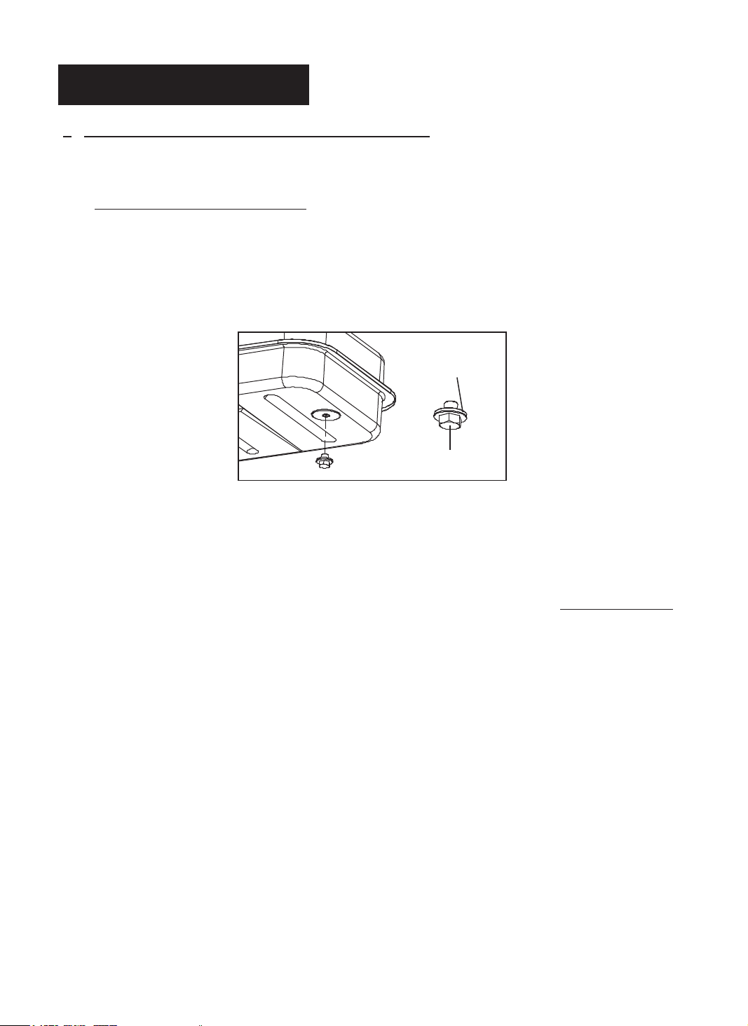
8. LONG TERM STORAGE OF YOUR HEATER
1. Remove fuel drain bolt from rear bottom side of fuel tank using 3/4” socket or adjustable wrench and
drain.
2. Using a small amount of kerosene, swirl and rinse the inside of the tank.
NEVER mix water with the kerosene as it will cause rust inside the tank.
Pour the kerosene out making sure that you remove it all.
IMPORTANT : Do not store kerosene over summer months for use during next heating season.
Using old fuel could damage heater.
3. Reinstall Fuel Drain Bolt to Fuel tank and tighten firmly using 3/4” socket or adjustable wrench.
IMPORTANT : Before reinstalling the fuel drain bolt, make sure the seal is on the bolt. If the seal is
not used the bolt cannot be installed correctly and the fuel tank will leak.
4. Store heater in dry well ventilated area. Make sure storage place is free of dust and corrosive fumes.
5. Store the heater in the original box with the original packing material and keep the USER’S MANUAL
with the heater.
Fuel Drain Bolt
Seal
Figure 5. Drain Bolt
9. MAINTENANCE
WARNING!! NEVER SERVICE HEATER WHILE IT IS PLUGGED IN
OR WHILE HOT!
USE ORIGINAL EQUIPMENT REPLACEMENT PARTS. Use of third party
or other alternate components will void warranty and may cause unsafe
operating conditions.
A.) UPPER SHELL REMOVAL
B.) FAN BLADES AND AIR DEFLECTOR
CLEAN EVERY SEASON OR AS NEEDED.
- Remove upper shell (See figure 6 above)
- Clean fan blades and air deflectors using a soft cloth
moistened with kerosene or solvent.
- Dry fan blades and air deflectors thoroughly.
- Reinstall upper shell.
AIR DEFLECTOR
FAN BLADE
Figure 7. Fan Blades and Air Deflectors
-Remove screws along each side and top of
heater using medium phillips screw driver.
-Lift upper shell off.
(See Figure 6)
Figure 6. Upper Shell Removal
9
NEVER LEAVE THE HEATER
UNATTENDED WHILE BURNING!
C.) SPARK PLUG
CLEAN AND REGAP EVERY 600 HOURS
OPERATION OR REPLACE AS NEEDED.
- Remove upper shell (See page 9).
- Remove spark plug wire from spark plug
(See Figure 8)
- Remove spark plug from burner head using
medium phillips screw driver.
- Clean and regap spark plug electrodes to
0.14”(3.5mm)gap.
- Reinstall spark plug in burner head.
- Attach spark plug wire to spark plug.
- Reinstall upper shell.
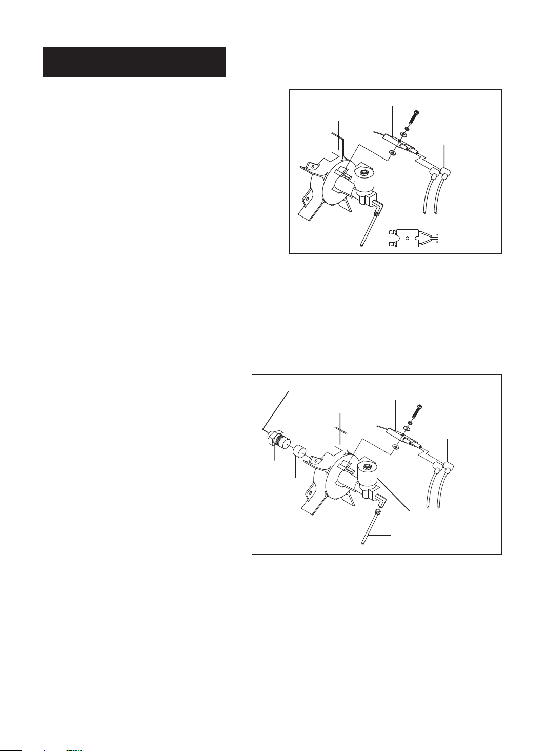
D.) NOZZLE
REMOVE DIRT IN NOZZLE AS NEED
(See page 14)
- Remove upper shell (See page 9).
- Remove fuel line from solenoid valve using
1/4” wrench.
- Remove spark plug wire from spark plug.
- Remove spark plug from burner head using medium
phillips screw driver.
- Remove five screws using medium phillips screwdriver
and remove burner head from
combustion chamber.
- Carefully remove nozzle from burner head
using 5/8” socket wrench.
- Blow compressed air through face of
nozzle.
(this will remove any dirt in nozzle)
- Inspect nozzle for damage. If damaged
or clogged, replace nozzle.
- Make sure plug is in place on burner
head.
- Reinstall nozzle into burned head and
tighten firmly. (175~200 inch-pounds)
- Reinstall spark plug in burner head.
- Attach burner head to combustion
chamber.
- Attach spark plug wire to spark plug.
- Attach fuel line to solenoid valve
tighten firmly.
- Replace upper shell.
Figure 8. Spark Plug
BURNER HEAD
SPARK PLUG
SPARK PLUG WIRE
GAP
Figure 9. NOZZLE
BURNER HEAD
NOZZLE FOACE
FUEL LINE
SOLENOIO VALUE
SPARK PLUG
SPARK PLUG WIRE
NOZZLE
PLUG
10
NEVER LEAVE THE HEATER
UNATTENDED WHILE BURNING!
11
NEVER LEAVE THE HEATER
UNATTENDED WHILE BURNING!
F.) FUEL LINES
TIGHTENING FUEL LINES ANNUALLY OR AS NEEDED.
- Remove upper shell (See page 9).
- Remove fan guard (See Figure 11)
- Use 1/4” wrench and tighten fuel lines(A) at solenoid valve
and at pump. (See Figure 12)
- Use 3/8” wrench and tighten fuel lines (B) at pump, pump fuel filter assembly.
- Reinstall fan guard.
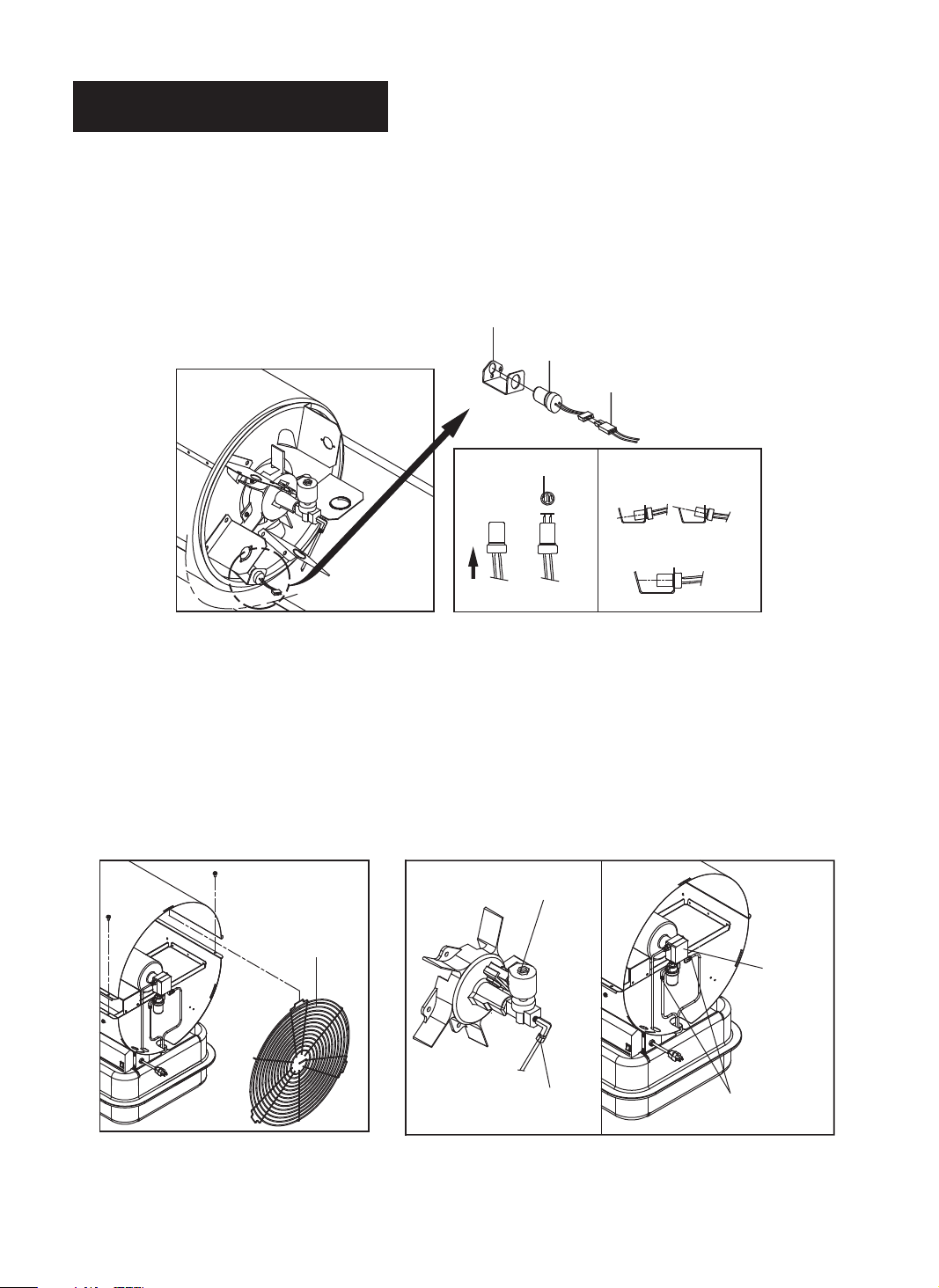
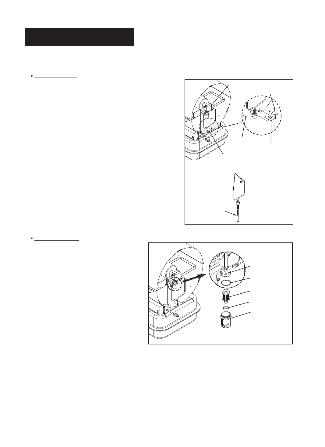
E.) PHOTOCELL
CLEAN PHOTO CELL ANNUALLY OR AS NEEDED.
- Remove upper shell (See Page 9)
- Remove photocell from photocell Bracket and disconnect photocell from connector.
- Clean photocell lens with cotton swab.
- Inspect photocell lens for damage. If damaged, replace photocell.
PHOTOCELL BRACKET
PHOTOCELL LENS
INSTALL PHOTOCELL
1)INCORRECT
2)CORRECT
PHOTOCELL
CONNECTOR
FUEL LINE(A)
FUEL LINE(B)
PUMP
FAN GUARD
SOLENOID VALVE
Figure 10. Clean photocell Lens
enil leuf nethgiT .21 erugiFFigure 11. Remove fan guard
NEVER LEAVE THE HEATER
UNATTENDED WHILE BURNING!
G.) FUEL FILTER
CLEAN TWICE PER HEATING SEASON OR AS NEEDED.
Tank Fuel Filter
- Remove fan guard.(See page 11).
- Disconnect fuel line (B) from pump and
pump fuel filter assembly with 3/8” wrench
(See Figure 13)
- Remove two screws that fix bracket-filter
to shell lower and remove bracket-filter.
- Carefully pry fuel filter loose from fuel
tank with flat end of screw driver.
- Wash fuel filter and fuel lines with clean
kerosene.
- Replace fuel filter into fuel tank.
- Replace bracket-filter to shell lower.
- Connect fuel lines (B) to pump and pump
fuel filter assembly.
- Reinstall fan guard.
PUMP
SCREW
SHELL LOWER
BRACKET-FILTER
PUMP FUEL FILTER ASSEMBLY
FUEL LINE(B)
FUEL FILTER
Pump Fuel Filter
- Remove fan guard.(See page 11)
- Unscrew (C.W) filter bottom from
filter top
with adjustable pliers.
- Remove fuel filter, gasket, magnet
from filter
bottom.(See Figure 14)
- Wash filter bottom with clean
kerosene.
- Wipe inside of filter bottom dry with
clean cloth.
- Wash Fuel filter in clean kerosene.
- Remove dirt attached magnet.
- Put clean magnet, fuel filter and gasket
back in filter bottom.
- Tighten firmly.
Figure 13. Remove Tank Fuel Filter
FILTER TOP
GASKET
FUEL FILTER
MAGNET
FILTER BOTTOM
Figure 14. Fuel Pump Filter
12
13
NEVER LEAVE THE HEATER
UNATTENDED WHILE BURNING!
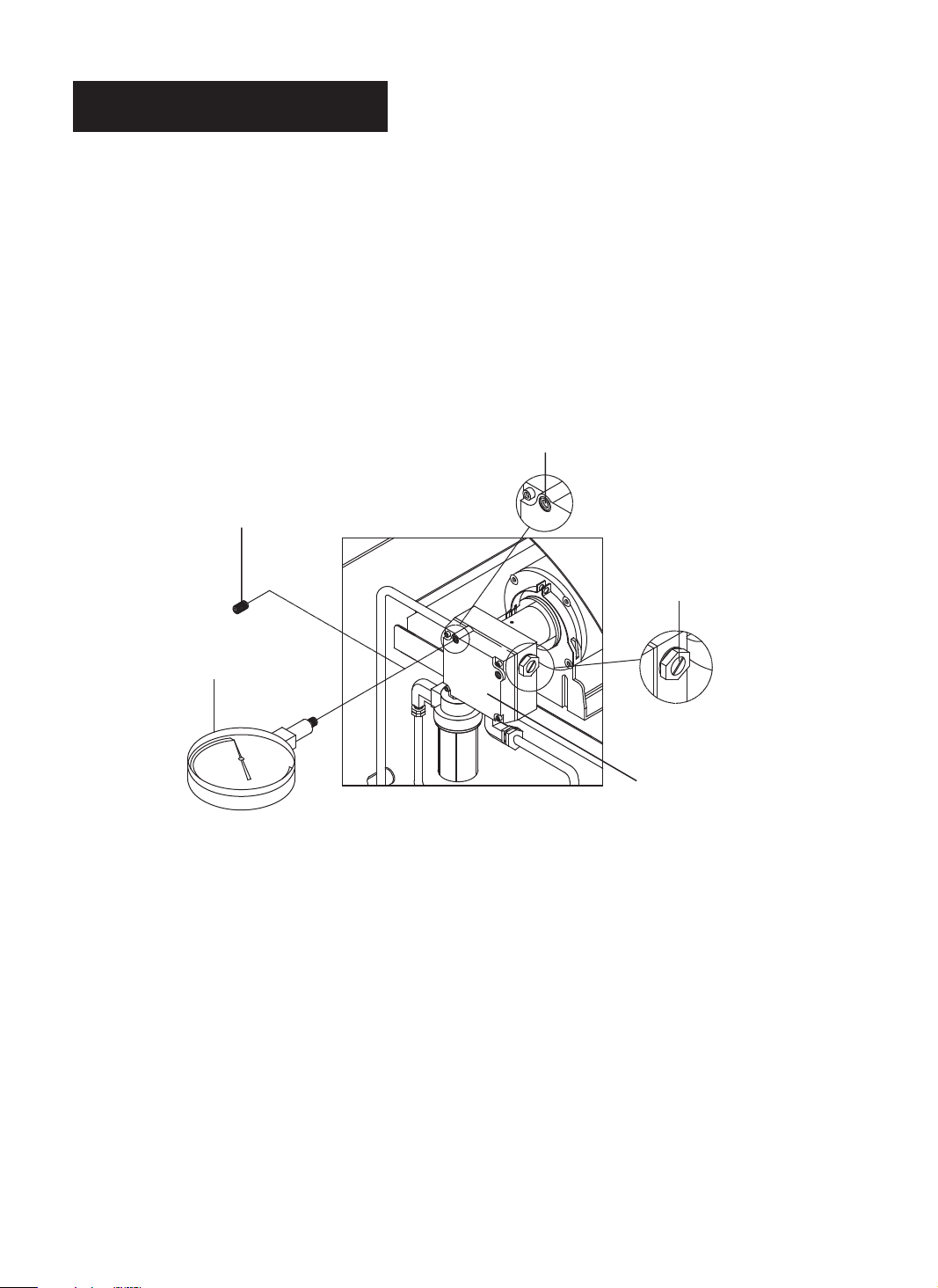
H.) PUMP PRESSURE ADJUSTIMENT
- Remove pressure gauge plug from pump with 1/8” allen wrench.
- Install accessory pressure gauge to pressure gauge port. (See Figure 15)
- Start heater (See operation, page 6)
Allow motor to reach full speed.
- Adjust pressure. (Using a small flat blade screw driver)
Turn pressure adj. Screw to clock wise to increase pressure.
Turn screw to counter clock wise to decrease pressure.
Set pump pressure to 110 PSI.
- Stop heater (See operation, page 6)
- Remove pressure gauge. Replace pressure gauge plug in pressure gauge port.
PRESSURE GAUGE PLUG
PRESSURE GAUGE PORT
PRESSURE ADJ.SCREW
PUMP
PRESSURE GAUGE
NOTE: USE ONLY ORIGINAL EQUIPMENT REPLACEMENT PARTS.
USE OF ALTERNATE OR THIRD PARTY COMPONENTS WILL VOID ANY WARRANTY
AND MAY CAUSE UNSAFE OPERATING CONDITION.
Figure 15. Adjusting Pump Pressure
NEVER LEAVE THE HEATER
UNATTENDED WHILE BURNING!
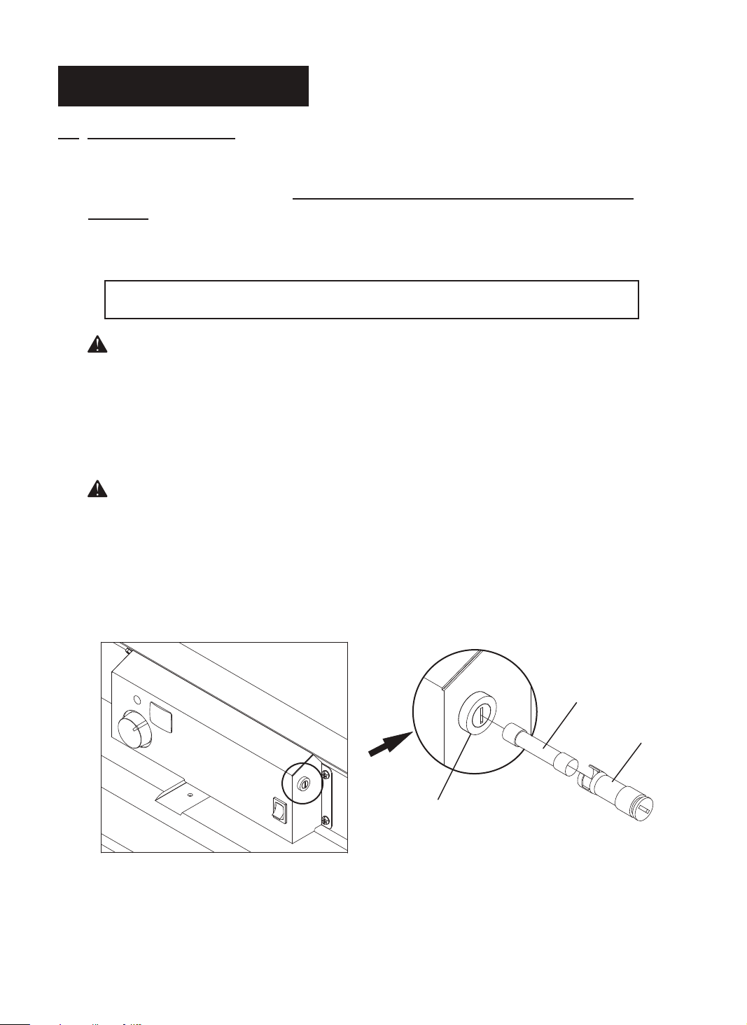
10. REPLACING FUSE
NOTICE : This heater is fuse protected.
If your heater fails to ignite, DO NOT RETURN YOUR HEATER TO THE
STORE.
Please follow the simple instruction below to inspect and change the fuse.
PROCEDURE FOR REPLACING FUSE
WARNING : SHOCK HAZARD
To prevent personal injury, unplug the power cord before replacing fuse.
1. Unplug heater.
2. Turn Fuse Cover COUNTERCLOCKWISE 45° using a flat blade screwdriver and remove Fuse from
Fuse Holder.
3. Replace Fuse.
WARNING : FIRE HAZARD
To avoid fire, Do not substitute with a higher or lower current rating.
4. Turn Fuse Cover CLOCKWISE 45° using a flat blade screwdriver while slightly pushing.
NOTE : Specified fuse rating : 250VAC/20A
Fuse
Fuse Holder
Fuse Cover
Figure 16. Replacing Fuse
14
NEVER LEAVE THE HEATER
UNATTENDED WHILE BURNING!
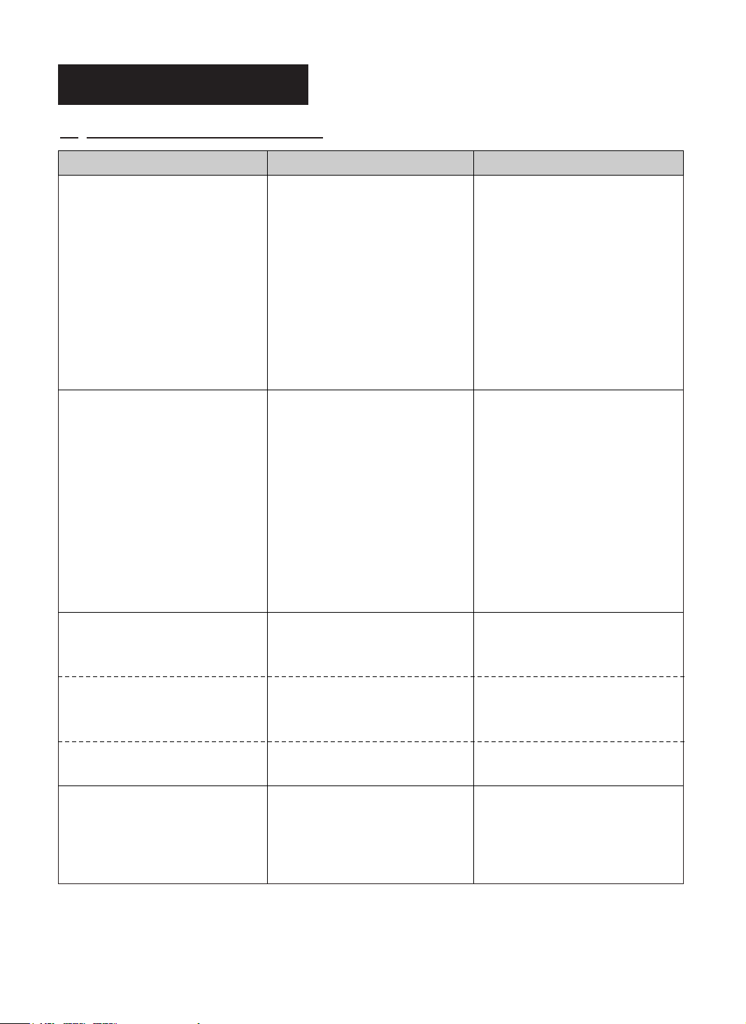
11. TROUBLE SHOOTING GUIDE
TROUBLE POSSIBLE CAUSE CORRECTIVE ACTION
Heater ignites but MAIN PCB
assembly shuts heater off after 2. Dirty Fuel Filter
a short period of time. 3. Dirt in Nozzle 2. See Fuel Filter, page 12.
(Indicator lamp is flickering and 4. Dirty Photocell Lens 3. See Nozzle, page 10.
room temp. display indicates “E1”) 5. Photocell Assembly not 4. Clean Photocell Lens, page 11.
Heater will not ignite but 1. No fuel in tank 1. Fill tank with kerosene
motor runs for a short period 2. Wrong pump pressure 2. See Pump Pressure Adjustment,
of time. (Indicator lamp is 3. Carbon deposits on spark page 13.
flickering and room temp. display plug and/or improper gap 3. See Spark Plug, page 10.
indicates “E1”) 4. Dirty fuel filter 4. See Fuel Filter, page 12.
Fan does not turn when heater 1. Thermostat setting is too low 1. Turn thermostat control knob
is plugged in and operating switch 2. Bad electrical connection to a higher setting
was in the “ON” position between motor and MAIN 2. Check electrical connections,
(Indicator lamp is on or flickering) .51 egap ,margaiD gniriW eeSylbmessa BCP
1. Wrong pump pressure 1. See Pump Pressure Adjustment,
properly installed. (Not 5. Make sure photocell boot is
seeing the flame) properly seated in bracket,
6. Bad electrical connection (See, page 11)
between photocell and MAIN 6. Check electrical connections.
7. Defective photocell 7. Replace photocell, page 11.
8. Temperature limit safety
device is overheated
5. Dirt in nozzle 5. See Nozzle, page 10.
6. Water in fuel tank 6. Flush fuel tank with clean
7. Bad electrical connection kerosene, page 9.
between ignitor and MAIN 7. Check electrical connections,
PCB assembly See wiring diagram, page 15.
8. Ignitor wire is not attached to
9. Defective ignitor See Spark Plug, page 10.
10.Defective solenoid valve
(not opening)
page 13.
.51 egap ,margaid gniriw eeSylbmessa BCP
8. Turn operating switch to “OFF”
and allow to cool (about 10 min.).
Then turn operating switch to
“ON” position.
9. Replace ignitor.
10.Check electrical connections and
voltage to solenoid valve. If
defective, replace solenoid valve.
.gulp kraps ot eriw rotingi hcattA.8gulp kraps
(Indicator lamp is flickering and 1. Sensor failure. 1. Replace sensor.
room temp. display indicates “E2”) .51 egap ,margaid gniriw eeS
(Indicator lamp is flickering and 1. Thermostat switch failure 1. Replace switch
room temp. display indicates “E3”) See wiring diagram, page 15.
Heater will not turn-on
(Indicator lamp is off)
1. No electrical power 1. Check to insure heater cord and
extension cord are plugged in.
Check power supply.
2. Blown fuse 2. Replace safety fuse on cover
display.
15
NEVER LEAVE THE HEATER
UNATTENDED WHILE BURNING!
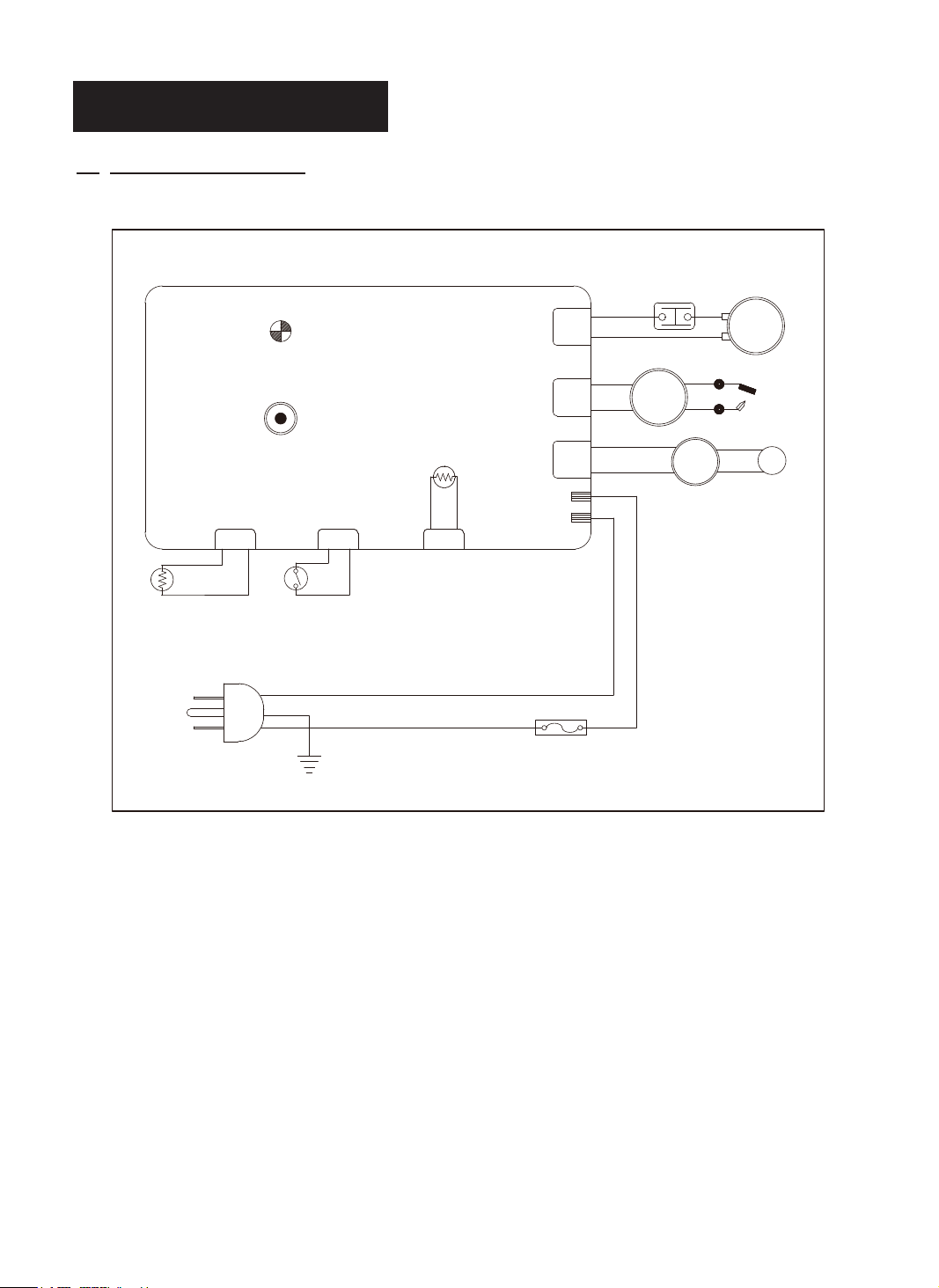
12. WIRING DIAGRAM
PHOTOCELL
AC120V
60Hz
CN5
WHITE
WHITE
POWER
PLUG
POWER LAMP
(LED)
THERMOSTAT
(TEMP. CONTROL)
CN8
YEL
YEL
OPERATING SWITCH
GREEN
EARTH
CONTROL PCB
ROOM
SENSOR
CN2(AC2)/
CN1(AC1)/
CN6
BLACK
BLACK
WHITE
RED
20A/250VAC
CN7
CN4
CN3
WHT
BLK
FUSE
BLACK
BLACK
BROWN
BROWN
ORANGE
RED
BLACK
LIMIT
CONTROL
IGNITOR
WHITE
BLACK
BLACK
PUMP
MOTOR
SOL.
VALV E
SPARK PLUG
BLACK
WHITE
CAPACITOR
50uF/400Vac
16
17
NEVER LEAVE THE HEATER
UNATTENDED WHILE BURNING!
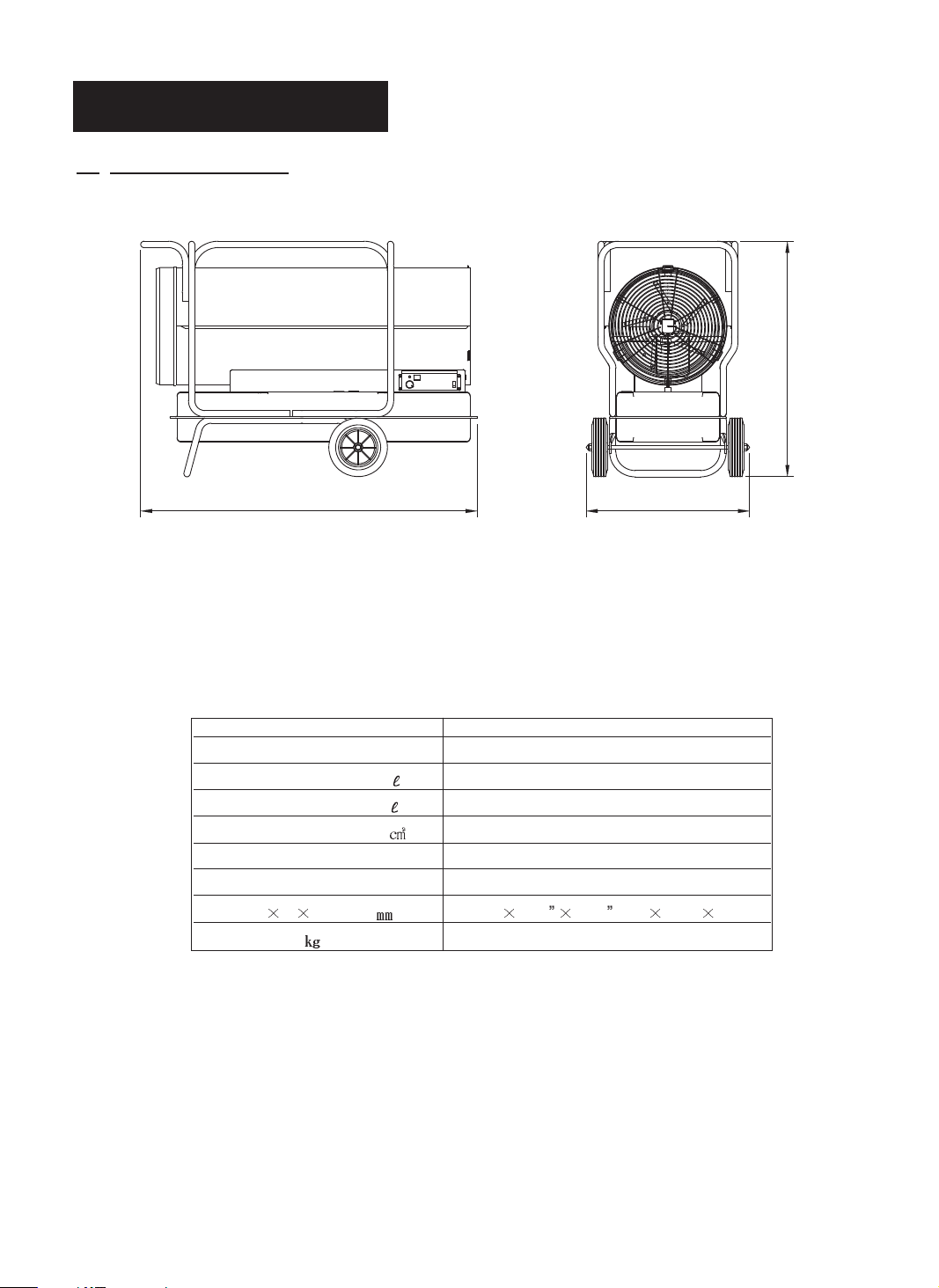
13. SPECIFICATIONS
LEDOM
000,056rH/UTB
Fuel Consumption-Gal./ ( ./Hr) 4.9(18.55)
Fuel Tank Capacity-Gal ( ) 50.0(189.25)
Pump Pressure PSI (kgf/ ) 110(7.73)
1.7/06/CAV021spmA/zH/stloV
1esahP
Size(W D H), Inch( ) 32.8” 69.2 48.7 (834 1758 1237)
Weight Ibs. ( )521(6.572)
)mm438("8.23)mm8571("2.96
48.7"(1237mm)
KFA650DGD
KFA650DGD
NEVER LEAVE THE HEATER
UNATTENDED WHILE BURNING!
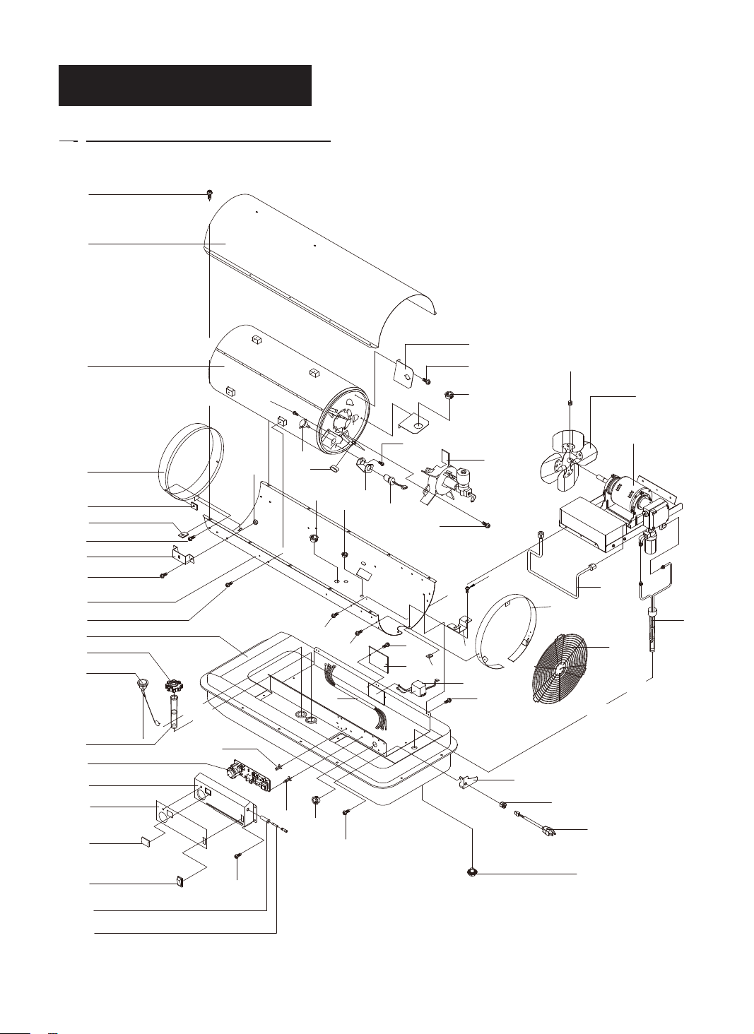
14. EXPLODED PARTS DRAWING
NOTE: SPECIFY MODEL NUMBER AND PART NUMBER WHEN ORDERING PARTS.
4
45
23
4
21
22
22
4
14
15
13
4
1
7
5
16
(KFA650DGD MODEL)
27
29
18
17
4
20
18
4
26
28
4
31
30
24
24
4
17
25
4
41
30
4
43
42
32
19
40
8
44
6
33
34
35
36
37
38
39
10
15
3
11
9
17
4
12
2
18
NEVER LEAVE THE HEATER
UNATTENDED WHILE BURNING!
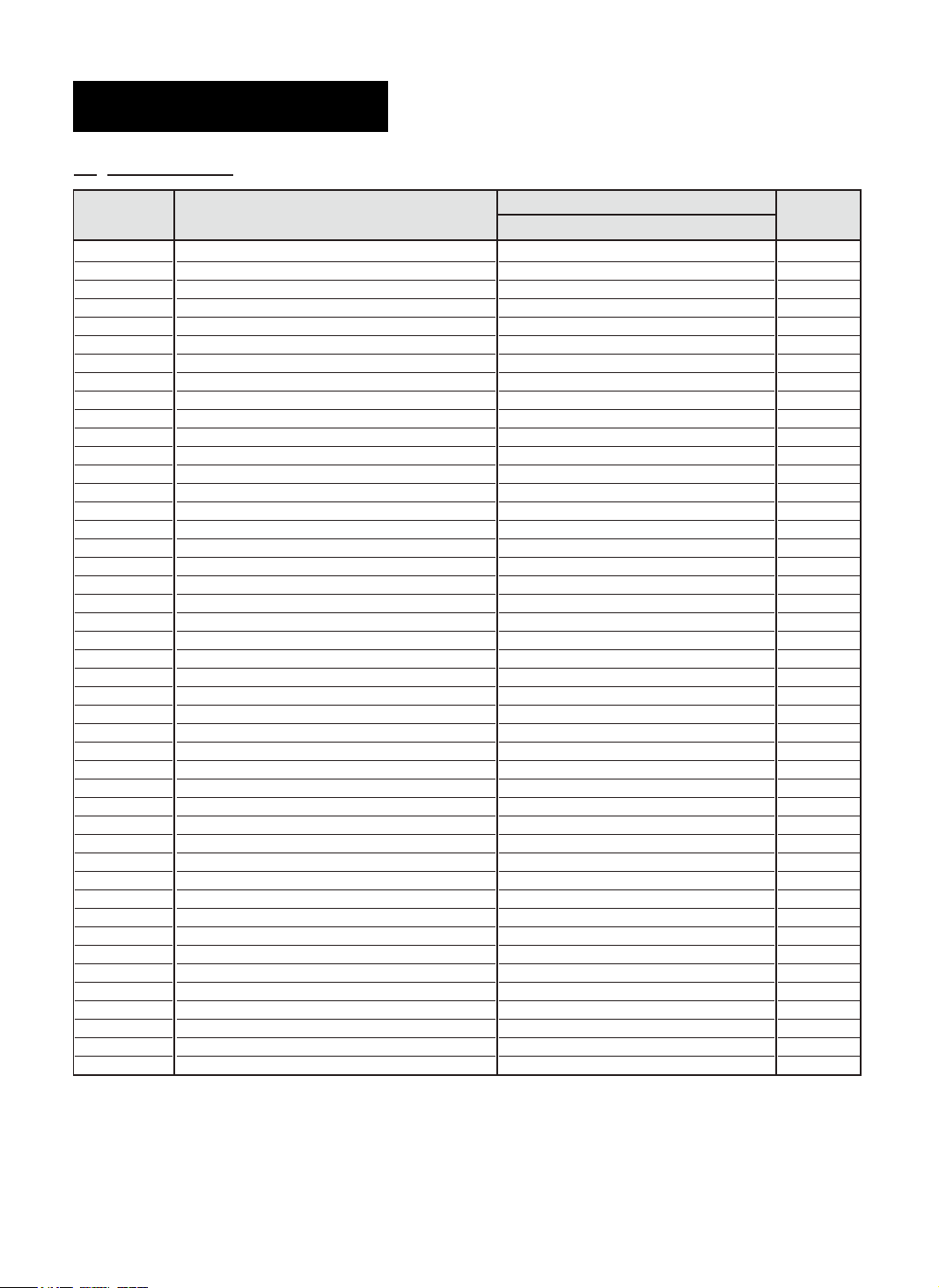
15. PARTS LIST
KEY No.
1
2
3
4
5
6
7
8
9
10
11
12
13
14
15
16
17
18
19
20
21
22
23
24
25
26
27
28
29
30
31
32
33
34
35
36
37
38
39
40
41
42
43
44
45
DESCRIPTION
Fuel Tank Assembly
Fuel Drain Bolt
Bracket-Cord
Flange Screw
Fuel Gauge
Fuel Filter
Fuel Cap
Filler Neck Assembly
Space Support
Card Support
Cord Bushing
Power Cord
Shell Lower
Bracket-Pipe
Bolt-HH
Lock Nut
Bushing Grommet(L)
Bushing Grommet(S)
Line - Fuel
Harness-Burner
Cone-Outside
Clip Nut
Chamber Assembly
Air Deflector
Burner Head Assembly
Bracket Photocell
Screw BH1
Photocell
Temperature Limit
Igniter
Cover Igniter
Motor & Pump Assembly
P.C.B Assembly
Cover Display
Rating Plate
Window Display
Operating Switch
Fuse Holder
Fuse
Guide Shell
Bracket-Filter
Fan Assembly
Bolt Standard Socket
Guard Fan
Shell Upper
PART No.
KFA650DGD
2151-0021-01
4329-0072-00
3131-0357-01
4319-0015-00
2156-0054-00
3221-0009-00
2151-0041-00
2155-0011-00
3713-0004-00
3713-0016-00
3712-0013-00
3980-0228-00
3111-0252-04
3131-0363-01
4321-0182-00
4331-0022-00
3231-0121-00
3231-0120-00
3740-0058-00
39D0-0785-00
2153-0016-01
3131-0182-00
2152-0083-00
3131-0361-00
2152-0084-00
3131-0159-00
4311-0068-00
2153-0017-00
38C0-0151-00
39E0-0029-00
3131-0309-01
2154-0046-00
215A-0076-00
3121-0376-01
3221-0072-09
3231-0113-00
39A0-0209-00
3930-0012-00
3920-0061-00
3121-0378-01
3131-0464-00
2154-0047-00
4323-0005-00
3561-0064-01
3111-0253-04
Quantity
1
1
2
43
1
1
1
1
5
3
1
1
1
2
4
4
6
1
1
1
1
14
1
4
1
1
2
1
1
1
1
1
1
1
1
1
1
1
1
1
1
1
1
1
1
FOR TECHNICAL ASSISTANCE SEE YOUR LOCAL RETAILER OR
CONTACT US AT:
Phone : 1-877-447-4768
19
20
NEVER LEAVE THE HEATER
UNATTENDED WHILE BURNING!
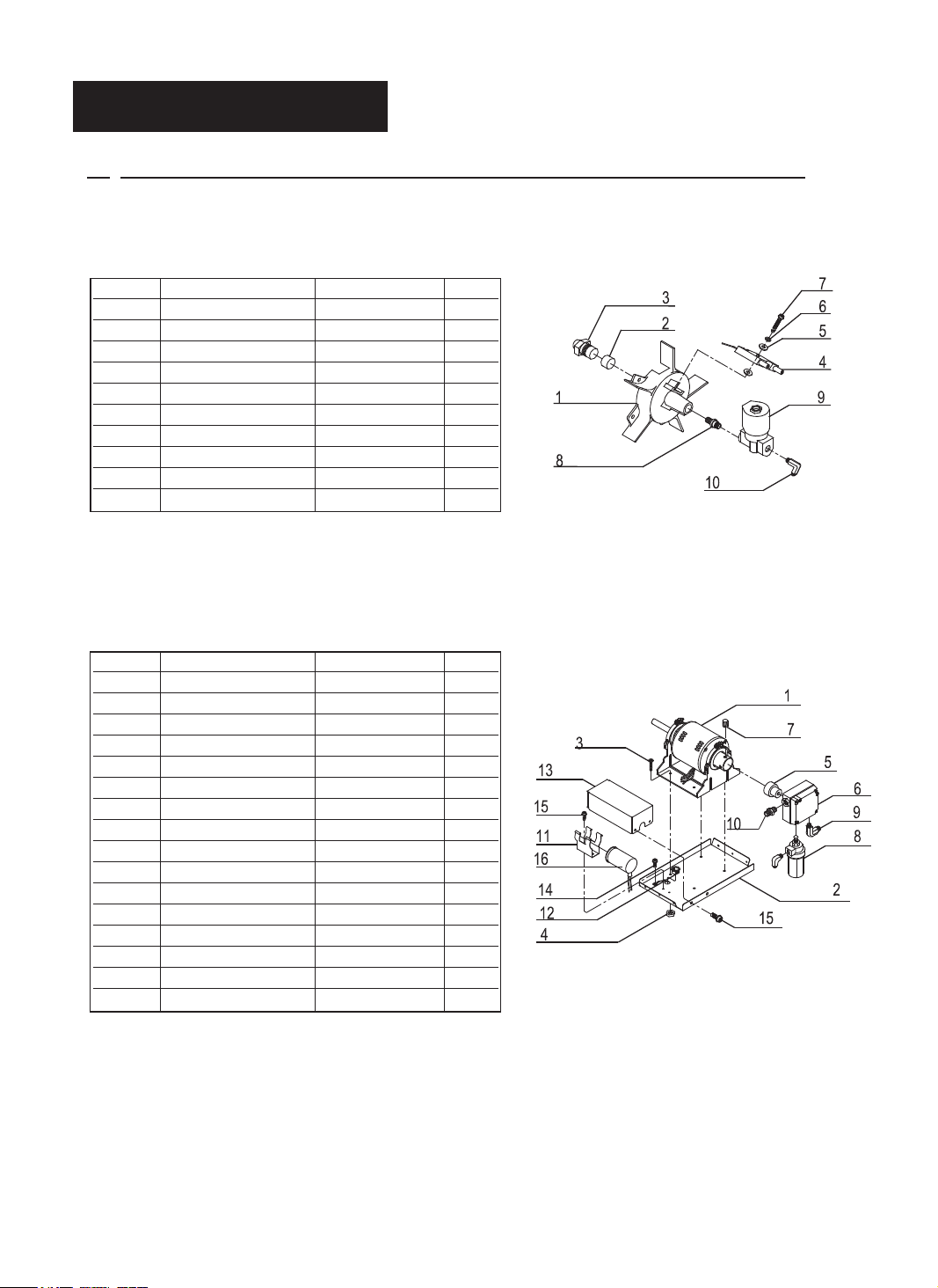
15. PARTS LIST
(BURNER HEAD ASSEMBLY & MOTOR AND PUMP ASSEMBLY)
NOTE: SPECIFY MODEL NUMBER AND PART NUMBER WHEN DRDERING PARTS.
KEY NO. DESCRIPTION PART NO. QTY.
1
Burner Head 3531-0012-00 1
2
Plug 3541-0060-00 1
3
Nozzle SP-KFA1028 1
4
Spark Plug SP-KFA1009 1
5
Fiber Washer 4349-0017-00 1
6
Spring Washer 4342-0009-00 1
7
Flange Bolt 4329-0013-00 1
8
Nipple-Straight 3541-0057-00 1
9
Solenoid Valve 39A0-0084-00 1
10
Elbow Male 3740-0037-00 1
KEY NO. DESCRIPTION PART NO. QTY.
1
Motor 3970-0111-00 1
2
Supporter-Motor 3121-0375-00 1
3
Bolt(HH) 4321-0182-00 4
4
Nut Lock 4331-0022-00 4
5
Coupling-Pump 3531-0013-00 1
6
Gear Pump 3740-0060-00 1
7
Bolt-Headless Socket 4323-0004-00 3
8
Filter Oil Assembly 3740-0034-00 1
9
Elbow Male 3740-0044-00 2
10
Fitting-Straight 3740-0039-00 1
11
Holder Condenser 3131-0295-00 1
12
Bushing Grommet(S) 3712-0120-00 1
13
Cover Condenser 3121-0338-00 1
14
Screw(TH2S) 4312-0046-00 1
15
Flange Screw 4319-0015-00 1
16
Capacitor 3820-0146-00 1
Figure 17. Burner Head Assembly
Figure 18. Motor and Pump Assembly
NEVER LEAVE THE HEATER
UNATTENDED WHILE BURNING!
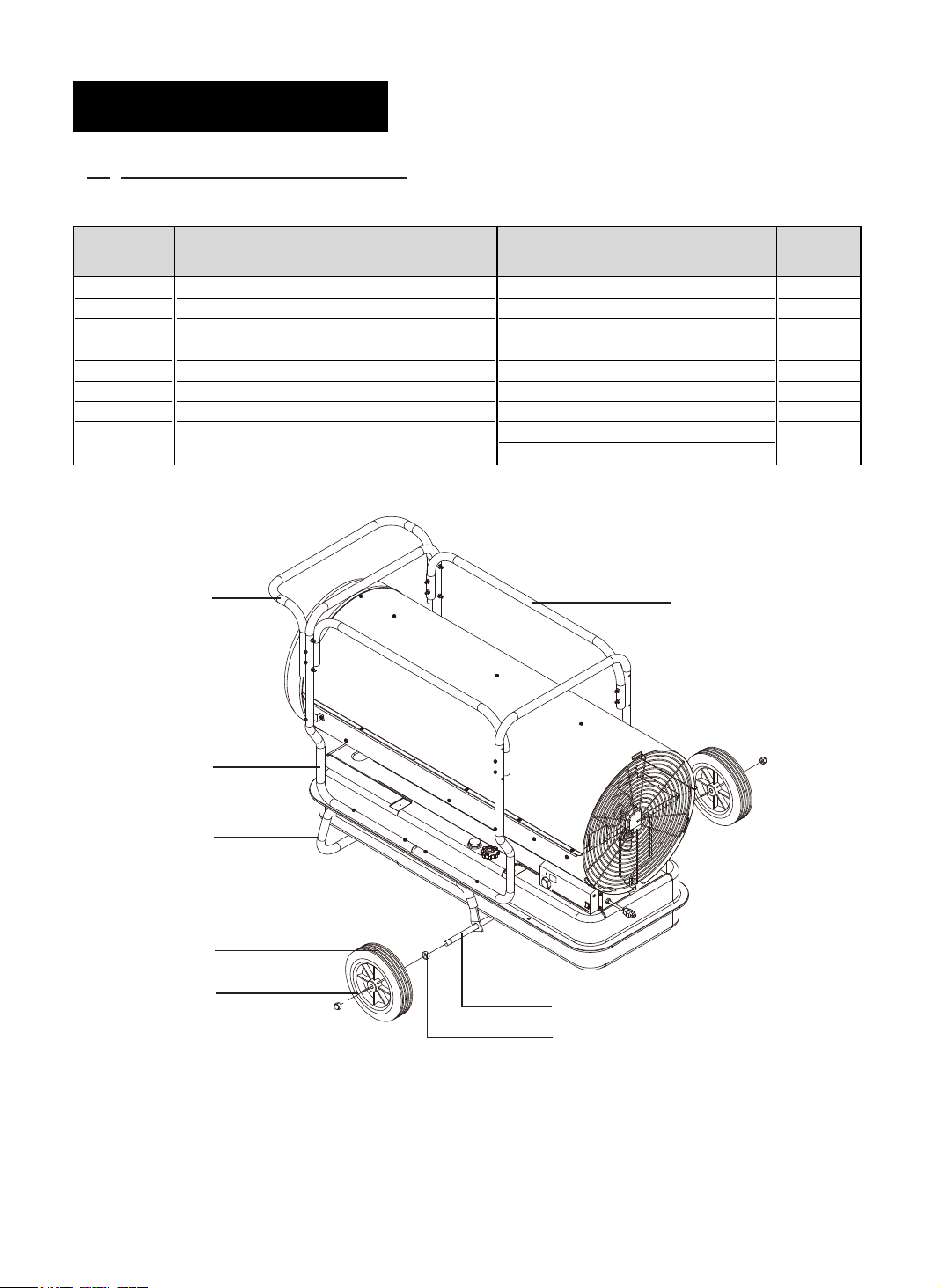
15. PARTS LIST
(Wheel and Handle)
NOTE: SPECIFY MODEL NUMBER AND PART NUMBER WHEN ORDERING PARTS.
KEY No.
1
2
3
4
5
6
7
7-1
7-2
Wheel Support Frame
Handle Frame
Frame Supporter
Front Handle
Wheel
Threaded Axle
Hardware Kit
Bushing
Cap Nut
4
DESCRIPTION
PART No.
3551-0041-00
3551-0043-00
3551-0044-00
3551-0042-00
3720-0004-00
3541-0094-00
HW-KFA1020
INCLUDED IN HARDWARE KIT
INCLUDED IN HARDWARE KIT
3
Quantity
1
2
2
1
2
1
1
2
2
7-2
2
1
5
6
7-1
21
Warranty
LIMITED WARRANTY:
This limited warranty is extended to the original retail purchaser of this Forced Air/Convection/Radiant Heater and warrants against any defect
in materials and workmanship for a period of one (1) year from the date of retail sale.GHP Group, Inc., at it’s option, will either provide
replacement parts or replace or repair the unit, when properly returned to the retailer where purchased or one of our service centers
as directed by GHP Group,Inc., within one (1) year of retail purchase. (Shipping costs, labour costs,etc. are the responsibility of the purchaser.)
DUTIES OF THE OWNER:
This heating appliance must be operated in accordance with the written instructions furnished with this heater. This warranty shall not excuse
the owner from properly maintaining this heater in accordance with the written ins
check or payment record must be kept to verify purchase data and establish warranty period. Original carton should be kept in case of
warranty return of unit.
WHAT IS NOT COVERED:
1. Damage resulting from use of improper fuel.
2. Damage caused by misuse or use contrary to the owners manual and safety guidelines.
3. Damage caused by a lack of normal maintenance.
4. Fuses
5. Use of non-standard parts or accessories.
6. Damage caused in transit. Freight charges on warranty parts or heaters to and from the factory shall be the responsibility of the owner.
This warranty does not imply or assume any responsibility for consequential damages that may result from the use, misuse, or the lack of
routine maintenance of this heating appliance. A cleaning fee and the cost of parts
maintenance. This warranty does not cover claims which do not involve defective workmanship or materials. FAILURE TO PERFORM
GENERAL MAINTENANCE (INCLUDING CLEANING) WILL VOID THIS WARRANTY.
THIS LIMITED WARRANTY IS GIVEN TO THE PURCHASER IN LIEU OF ALL OTHER WARRANTIES, EXPRESSED OR IMPLIED,
INCLUDING BUT NOT LIMITED TO THE WARRANTIES OF MERCHANTABILITY OF FITNESS FOR A PARTICULAR PURPOSE. THE
REMEDY PROVIDED IN THIS WARRANTY IS EXCLUSIVE AND IS GRANTED IN LIEU OF ALL OTHER REMEDIES. IN NO EVENT
WILL GHP GROUP, INC. BE LIABLE FOR INCIDENTAL OR CONSEQUENTIAL DAMAGES.
tructions furnished with this heater. A bill of sale, canceled
may be charged for appliance failures resulting from lack of
Some states do not allow limitations on how long an implied warranty
lasts, so the above limitation may not apply to you. Some states do not
allow the exclusion or limitation of incidental or consequential damages so the above limitation or exclusion may not apply to you.
CLAIMS HANDLED AS FOLLOWS:
1. Contact your retailer and explain the problem.
2. If the retailer is unable to resolve the problem, contact our Customer Service Dept. detailing the heater model, the problem, and proof
of date of purchase.
3. A representative will contact you. DO NOT RETURN THE HEATER TO GHP GROUP, INC. unless instructed by our Representative.
This warranty gives you
TO REGISTER THE WARRANTY ON YOUR HEATER, PLEASE FILL OUT THIS CARD COMPLETELY
AND MAIL WITHIN 14 DAYS FROM DATE OF PURCHASE OR REGISTER ON-LINE AT www.ghpgroupinc.com
NAME: _______________________________PHONE: ( ) _________________ EMAIL: ____________________________________
ADDRESS: ___________________________CITY: ________________________ STATE: _____________________ ZIP: ___________
MODEL: ______________________________SERIAL#: _____________________ DATE PURCHASED: _________________________
DEALER PURCHASED FROM: _________________________________________ TYPE OF STORE: __________________________
CITY & STATE WHERE PURCHASED: ___________________________________ PRICE PAID: _______________________________
Who primarily decided this purchase? Male Female 18-24 25-39 40-59 60 and over of age?
Do you own any other portable heaters? Yes No If yes, type ______________________ brand ____________________________
How do you intend to use your new heater? Construction Site Farm Warehouse/Commercial Garage/Outbuilding Other
How did you become aware of this heater?
TV Commercial Store Salesperson Other ____________________________________________________________________
What made you select this heater?
Do you:
Please give us your comments _____________________________________________________________________________________
Own Rent Would you recommend this heater to a friend? Yes No
legal rights and you may also have other rights which vary from state to state.
Please Take 1 Minute To Give Us Your Answers To The Following Questions.
In-Store Display Newspaper Ad Magazine Ad Friend/Relative
Style Size/Portability Price Package Brand Other __________________________
THANK YOU FOR COMPLETING THIS FORM!
Information will be held
WARRANTY REGISTRATION
days of date of purchase. You can also register your warranty on the internet at
www.ghpgroupinc.com. Complete the entire serial number. Retain this portion of the card
for your records.
GHP Group, Inc.
6440 W Howard St
Niles, IL 60714-3302
Tel: (877) 447-4768
www.ghpgroupinc.com
SAVE THIS CARD!
GHP Group, Inc.
6440 W Howard St
Niles, IL 60714-3302
Place
Postage
Stamp
Here
PRODUCTOS PARA INTERIORES/EXTERIORES
CALENTADORES PORTÁTILES
DE AIRE FORZADO DE QUEROSÉN
MANUAL DEL USUARIO
E INSTRUCCIONES PARA
EL FUNCIONAMIENTO
CUMPLE CON
ANSI A10.10-1998
CAN/CSA/B140.0-03
Y CSA B140.8-1967
MODELO : KFA650DGD
Antes de utilizar por primera vez este calentador, lea este MANUAL DEL
USUARIO atentamente. Este MANUAL DEL USUARIO ha sido diseñado
para instruirle la forma adecuada de ensamblar el calentador, brindarle
mantenimiento, guardarlo y lo más importante: cómo hacerlo funcionar de
manera segura y eficaz. Conserve este manual para referencia futura.
CONSUMIDOR: Conserve este manual para referencia futura.
¿Preguntas, problemas, partes faltantes? Antes de regresar al distribuidor, llame a nuestro
departamento de servicio al 877-447-4768 de 8:30 a.m. a 4:30 p.m. hora estándar del centro,
de lunes a viernes o envíenos un correo electrónico a customerservice@ghpgroupinc.com.
IMKFADG-KDS
¡NUNCA DEJE EL CALENTADOR
DESATENDIDO CUANDO ESTÉ ENCENDIDO!
PELIGRO: EL USO INADECUADO DE ESTE CALENTADOR PUEDE OCASIONAR LESIONES
SERIAS O LA MUERTE POR QUEMADURAS, FUEGO, EXPLOSIÓN, DESCARGA
ELÉCTRICA Y/O ENVENENAMIENTO POR MONÓXIDO DE CARBONO.
ADVERTENCIA:
1. ¡RIESGO DE CONTAMINACIÓN DE AIRE EN INTERIORES!
• Utilice este calentador sólo en áreas bien ventiladas. Proporcione al menos un espacio de tres pies cuadrados
(2.800 cm2) de aire puro externo por cada 100.000 BTH/h de rendimiento de salida.
• Las personas con porblemas respiratorios deben consultar con un médico antes de utilizar el calentador.
• Enveneamiento con monóxido de carbono: Los síntomas de envenenamiento con monóxido de carbono se parecen
. Si tiene estos síntomas, puede que el calentador no esté
funcionando adecuadamente. ¡Trasládese al aire libre inmediatamente! Haga revisar el calentador. A algunas personas
les afecta más el monóxido de carbono que a otras. Estas incluyen las mujeres embarazadas, personas con enfermedades
encia del alcohol o en lugares a gran altura.
• Nunca utilice este calentador en áreas habitables o utilizadas como dormitorio.
2. RIESGO DE QUEMADURAS/INCENDIO/EXPLOSIÓN
• NUNCA utilice ningún otro combustible distinto del querosén 1- K, #1 / #2 Diésel / Gasolina, JET A o JP-8 funcionan
en este calentador.
• NUNCA utilice combustibles tales como gasolina, benceno, diluyentes de pintura u otros compuestos de aceite en este
calentador. (RIESGO DE INCENDIO O EXPLOSIÓN)
• NUNCA utilice este calentador donde puedan estar presentes vapores in
• NUNCA rellene el tanque de combustible del calentador mientras esté funcionando o esté aún caliente.
PRECAUCIÓN:
Caliente mientras está en funcionamiento. No
toque. Mantenga alejados del calentador a los niños, la ropa y los combustibles.
Separación mínima: Salida: 8 pies (250cm) / de los costados, parte superior y trasera: 4 pies (125cm)
• NUNCA bloquee la entrada de aire (trasera) ni la salida de aire (frontal) del calentador.
• NUNCA coloque redes de conductos al frente o detrás del calentador.
• NUNCA mueva o manipule el calentador mientras está caliente, operando o enchufado.
• NUNCA transporte el calentador con combustible en el tanque.
• Cuando se utiliza con un termostato opcional o si está equipado con un termostato, el calentador puede
encenderse en cualquier momento.
• SIEMPRE
• SIEMPRE mantenga a los niños y los animales apartados del calentador.
• El almacenaje de combustible por volumen debe estar mínimo a 25 pies (7,6 m) de los calentadores, antorchas,
generadores portátiles u otras fuentes de ignición. Todo el almacenaje de combustible debe realizarse de acuerdo con
las autoridadesfederales, estatales o locales que tengan jurisdicción.
3. ¡RIESGO DE DESCARGA ELÉCTRICA!
• Utilice únicamente la corriente eléctrica (voltaje y frecuencia
• Utilice únicamente un tomacorriente de tres patas, con conexión a tierra y cable de extensión.
• SIEMPRE instale el calentador de forma que no quede directamente expuesto al rocío del agua, lluvia, goteo de agua o viento.
• SIEMPRE desenchufe el calentador cuando no esté en uso.
ADVERTENCIA: Este producto y el combustible utilizado para poner en funcionamiento
este producto (kerosén o otros combustibles aprobados), y los productos de la combustión de tal
combustible, pueden exponerlo a sustancias químicas como el benceno que, según el estado de California,
puede provocar cáncer y daños reproductivos.
Para obtener más información, visite www.p65Warnings.ca.gov
RESIDENTES DE MASSACHUSETTS: La ley del estado de Massachusetts prohíbe el uso de este calen-
de calefacción en Massachusetts requiere el permiso del Dpto. de Bomberos local (M.E.L.C., sección 10A)
para vivienda humana. El uso de este dispositivo
RESIDENTES DE CANADÁ: El uso de este calentador deberá conformarse con las autoridades que
tengan jurisdicción y con la Norma CSA B139.
RESIDENTES DE LA CIUDAD DE NUEVA YORK: Para uso únicamente en las obras en construcción de
e aprobación NYCFD Nº 5034 y 5037.
1
 Loading...