


TM
PT-19
•BUILDS QUICKLY
•REALISTIC FUN SCALE MODEL
•HUGE, 89" WINGSPAN (IMAA Legal)
READ THROUGH THIS INSTRUCTION MANUAL FIRST. IT CONTAINS IMPORTANT INSTRUCTIONS AND WARNINGS CONCERNING THE ASSEMBLY AND USE OF THIS MODEL
WARRANTY
Dynaflite guarantees this kit to be free from defects in both material and workmanship at the date of purchase. This warranty does not cover any component parts damaged by use or modification. In no case shall Dynaflite's liability exceed the original cost of the purchased kit. Further, Dynaflite reserves the right to change or modify this warranty without notice. In that Dynaflite has no control over the final assembly or material used for final assembly, no liability shall be assumed nor accepted for any damage resulting from the use by the user of the final user-assembled product. By the act of using the user-assembled product, the user accepts all resulting liability. If the buyer is not prepared to accept the liability associated with the use of this product, return this kit immediately in new and unused condition to the place of purchase.
©Copyright 1997 |
PT19P03PrintedinUSA |

|
|
|
|
At Dynaflite we take pride in offering kits that are |
|
|
|
|
simple and straight forward to build and provide |
|
|
|
|
value for your modeling dollar. Because of the size |
|
|
|
|
and cost of this model we assume you have built |
Introduction |
...................................................... |
|
|
2several models and have a general working |
Precautions....................................................... |
|
3 |
knowledge of modeling and its terms. If you HAVE |
|
Preparations..................................................... |
|
3 NOT built and flown several kits, do yourself a favor |
||
Required Accessories ....................................... |
|
3 and get some experience before beginning this kit. |
||
Suggested Supplies ......................................... |
|
3 |
|
|
Optional Accessories ....................................... |
|
4 |
|
|
Building |
Notes................................................. |
|
4 |
|
Adhesives ....................................................... |
|
|
4 |
|
Common |
Abbreviations.................................... |
|
5 |
|
Types of Wood ................................................ |
|
5 |
|
|
Metric Conversion............................................ |
|
5 |
|
|
Die Patterns ................................................ |
|
6&7 |
|
|
Build the Fuselage ............................................... |
|
8 |
|
|
Build the Wing ..................................................... |
|
12 |
|
|
BuildtheAilerons ........................................................... |
|
16 |
Your PT-19 is not a toy, but a sophisticated working |
|
Build the Stabilizer & Elevators ........................... |
|
17 |
model that functions like a full-size airplane. Because |
|
Build the Vertical Fin & Rudder ......................... |
|
19 |
of its performance, if you do not assemble and |
|
Mount the Wing to the Fuselage ......................... |
|
20 |
operate the PT-19 correctly, you could possibly injure |
|
FinalAssembly ................................................. |
|
22 |
yourself or spectators and damage property. |
|
Finishing.......................................................... |
|
|
26 To make your R/C modeling experience totally |
|
Set The Control Throws................................... |
|
27 enjoyable, we recommend that you get assistance |
||
Balance Your Model....................................... |
|
27 |
with assembly and your first flights from an |
|
Preflight.................................................. |
|
|
27 |
experienced, knowledgeable modeler. You'll learn |
At Home............................................................... |
|
|
27 faster and avoid risk to your model before you're |
|
At the Flying Site ........................................... |
|
28 |
truly ready to solo. Your local hobby shop has |
|
Engine Safety Precautions................................ |
|
28 information about flying clubs in your area whose |
||
FLYING............................................................. |
|
|
28 |
membership includes qualified instructors. |
Find a Safe Place to Fly.................................. |
|
28 |
|
|
Takeoff.......................................................... |
|
|
29 You can also contact the national Academy of Model |
|
Flight......................................................... |
|
|
29 Aeronautics (AMA), which has more than 2,300 |
|
Landing ........................................................ |
|
|
29 chartered clubs across the country. We recommend |
|
Terms & Definitions ........................................ |
|
30 you join the AMA which will provide you with |
||
Cockpit & Wing Tip Patterns........... |
Center Spread |
insurance coverage at AMA club sites and events. |
||
|
|
|
|
AMA Membership is required at chartered club |
|
|
|
|
fields where qualified flight instructors are available. |
|
|
|
|
Contact the AMA at the address or toll-free phone |
|
|
|
|
number below. |
Congratulations on your choice of this |
kit for your |
Academy of Model Aeronautics |
||
5151 East Memorial Drive |
||||
next project. The Fairchild PT-19 is a Fun Scale® |
Muncie, IN 47302 |
|||
model of a true classic aircraft and has the presence |
(800) 435-9262 |
|||
that only a big model can carry off. |
|
|
Fax (765) 741-0057 |
|
2
1. You must assemble the plane according to the instructions. Do not alter or modify the model, as doing so may result in an unsafe or unflyable model. In a few cases the instructions may differ slightly from the photos or plan. In those instances the written instructions should be accepted as correct.
2.You must take time to build straight, true and strong.
3.You must install all R/C and other components so that the model operates properly on the ground and in the air.
4.You must test the operation of the model before the first and each successive flight to insure that all equipment operates correctly. You must also make certain that the model has remained structurally sound.
NOTE: We, as the kit manufacturer, can provide you with a quality kit and great instructions, but ultimately the quality and flyability of your finished model depends on how you assemble it; therefore, we cannot in any way guarantee the performance of your completed model and no representations are expressed or implied as to the performance or safety of your completed model.
These are the items "not included" with your kit, that you will need to purchase separately. Items in parentheses (GPMQ3141) are suggested part numbers recognized by distributors and hobby shops and are listed for your ordering convenience. GPM is the Great Planes® brand, TOP is the Top Flite® brand and HCA is the Hobbico® brand.
4 channel radio with 3 standard, 2 high torque and one quarter scale servo.
Engine - 1.08 to 1.5 2-stroke or 1.2 to 1.6 4-stroke
Engine mount and mounting hardware 16oz.Fueltank(GPMQ4107) Standard fuel tubing (GPMQ4131)
(2) 5" to 6" main wheels
(1)1-1/2" tail wheel (GPMQ4243)
(4)1/4" Wheel collars (DUBQ1200)
(2)1/8" Wheel collars (GPMQ4304)
Top Flite® MonoKote® covering film (4 rolls) or Coverite™ 21 st Century® Fabric
Paint for fuelproofing, the engine cowl and the windshields
(1)OR(2) 1/3 Scale pilot(s)
1/4" Latex Foam Rubber (HCAQ1000)
These are the adhesives and supplies that you will need to build your Pt-19. We recommend Great Planes Pro™ CA and Epoxy
Please inventory and inspect all parts carefully |
4 oz. Thin CA Adhesive - (GPMR6004) |
before starting to build! If any parts are missing, |
2 oz. Thick CA Adhesive - (GPMR6015) |
broken or defective or if you have any questions |
CA Accelerator - (HCAR3750) |
about building or flying this model, please call us at |
CA Applicator Tips - (HCAR3780) |
(217) 398-8970 and we'll be glad to help. If you are |
6-Minute Epoxy - (GPMR6045) |
calling for replacement parts, please look up the |
30-Minute Epoxy - (GPMR6047) |
part numbers and have them ready when calling. |
4 oz. Aliphatic Resin Glue (GPMR6161) |
3
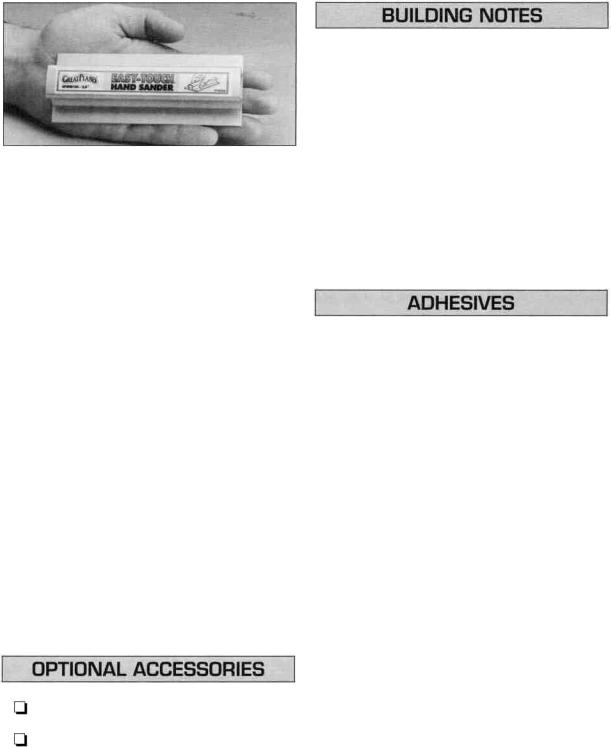
A flat, durable, easy-to-handle sanding tool is a necessity for building model airplanes. Great Planes makes a complete range of Easy-Touch'" Bar Sanders and replaceable Easy-Touch adhesive-backed sandpaper. On our workbench, we have four 11" Easy-Touch Bar Sanders, equipped with #50, #80, #150 and #220-grit sandpaper. This setup is all that is required for almost any sanding task. Custom sanding blocks can be made from balsa for sanding hard-to- reach spots. We also keep some #320-grit wet-or-dry sandpaper for finish sanding before covering.
For future reference, here's a list of Easy-Touch Bar Sanders and adhesive-backed sandpaper:
5-1/2" Bar Sander (GPMR6169)
11 "Bar Sander (GPMR6170)
22" Bar Sander (GPMR6172)
12' Roll of adhesive-backed sandpaper, 80-grit (GPMR6180)
150-grit (GPMR6183)
220-grit (GPMR6185)
Assortment pack of 5-1/2" strips (GPMR6189)
Robart Oleo landing gear struts (ROBQ1600)
Midwest scale instrument panel (MIDQ1105)
IMPORTANT: During construction you will be using a number of balsa sticks to frame various assemblies. Ample material is included but you should study the plans, then make an effort to cut the longest pieces you will need first. Label the pieces as you cut them for later reference. By doing this now, you won't have to splice pieces together later.
This kit is built with three types of glue.
Cyanoacrylate: CA glues cure almost instantaneously and are moderately strong. There are different viscosities of CA's intended for different conditions you will encounter when you build. Thin CA is great for "tack-gluing," for glue joints that fit well and for parts that are already joined but need to be permanently bonded. Medium CA is used for general construction where you apply glue to one part, then join it to another part. Thick CA is great for glue joints that don't fit perfectly or parts that require a little time for positioning before the glue cures. You will encounter many other conditions that require one or the other types of CA.
Always use CA in a well ventilated area. Open some windows or place a fan in the room to circulate the air. Do not lean directly over your work when you use CA and look away while it cures or "sets off." CA can cure immediately upon contact with skin so if you accidentally bond your fingers, do not use vigorous motion to separate them. Use CA Debonder (GPMR6039) or acetone (nail polish remover) or soak your fingers in warm water for a few minutes.
4
Never point the tip of a CA bottle toward your face and be especially careful when you unclog a CA tip. Hobbico CA Applicator Tips (HCAR3780) are highly recommended and will help keep the bottle from clogging. Keep paper towels or tissues close by to immediately absorb excess CA dropped on your model or work area. Read all the warning labels on your CA bottle. CA Accelerator is a chemical that you can spray over uncured CA to make it cure immediately. A mist spray of accelerator will do the job. Do not inhale the vapors! Some modelers "preprime" the parts to be glued with accelerator, join them, then add the CA. This way the CA is guaranteed to cure immediately. This prepriming is especially handy when you use thin CA because it will cure before all of the glue soaks into the wood away from the glue joint. We do not recommend you build your entire model with this method and use accelerator only when necessary. Often, overspray from accelerator used hours or even days earlier on nearby glue joints will cause the CA you use on the next step to cure prematurely and unexpectedly - so be careful!
Aliphatic Resin - Resin glues require that parts be pinned or clamped together while the glue dries/- typically 1 5 - 3 0 minutes. Resin glues are very strong and work well with balsa and plywoods.
Epoxy - Epoxy glues are the strongest but require the most time to cure. Six-minute epoxy cures the fastest; it sets within six minutes but is not fully cured for one hour or more. Thirty-minute epoxy is the strongest as it allows the epoxy to soak into the wood thoroughly. While it sets within 30 minutes, it will not be fully cured for two or more hours.
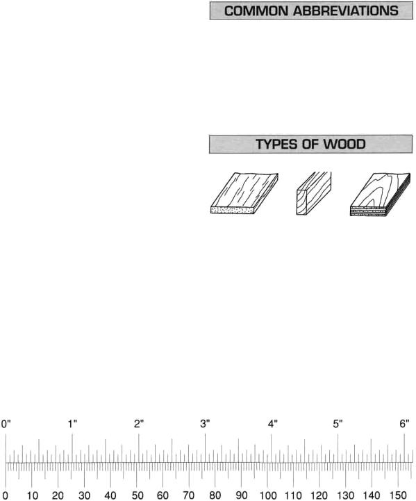
Inch Scale
Metric Scale
Fuse = Fuselage |
Stab = Horizontal Stabilizer |
Ply = Plywood |
LE = Leading edge (front) |
" = Inches |
TE = Trailing edge (rear) |
Balsa Basswood Plywood
5

DIE PATTERNS
6
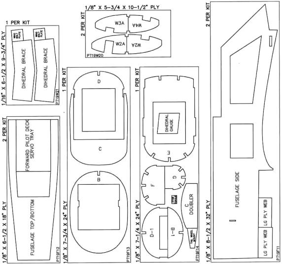
DIE PATTERNS
7
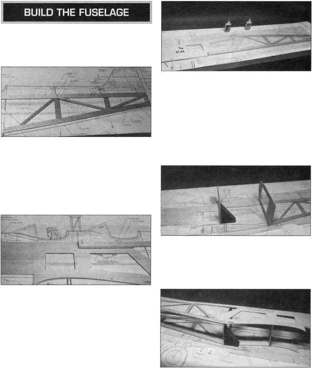
 1. Place the fuselage drawing on your workbench and cover it with wax paper from bulkhead D aft. Begin construction by building the right rear side structure.
 2. Using two 1 /4" x 15/16" x 42" balsa sticks, cut and fit the rear side stringers. Cut the longest pieces first. Pin and glue the parts into position.
 3. Cut the diagonals from a 1/4" x 1/2" x 30" balsa stick and glue into position.
 4. Fit the ply fuselage front to the fuse rear. Cut doublers for the two joints from a 1 /8" x 1 /4" x 30" balsa stick. When satisfied with the fit, glue them with 6-minute epoxy.
 5. The left fuselage side is built over the right side. Remove the right side from your building board and turn it over. Use the leftover 1 /8" x 1 /4" stick to shim the forward ply side. Cover the side with wax paper. Follow steps 2, 3 and 4 to build the left side, aligning the parts over the right side.
 6. Place the right fuselage side over the plans and mark the locations of bulkheads B, C, D, E, F, and G on the side. Place the left side over the right and transfer the marks to the left side. Next, mark each former at the center of the bottom edge. Place the fuselage plan on your building board and draw a line down the length of the plans along the fuselage center with a long straightedge. These marks and lines will be used to align the fuselage in the following steps.
 7. Glue bulkheads D and E to the right fuselage side using 6-minute epoxy. Be sure the bulkheads are at a 90 degree angle to the side. Epoxy will produce the strongest joint but you can use thin CA with accelerator if you are in a hurry.
 8. Glue the left fuselage side to bulkheads D and E using 6-minute epoxy. Align the side with the marks
8
you made earlier. Before the glue cures, sight across the top of both sides to double check the alignment.
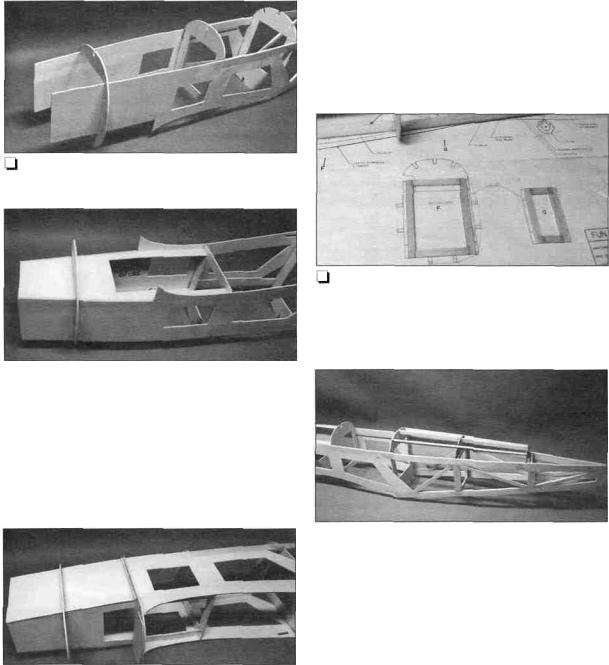
9. Slip bulkhead B over the outside of the fuselage. Do NOT glue until the next step.
 10. Glue the top and bottom deck into position with 30-minute epoxy. Also glue bulkhead B to the fuselage sides and both decks with 30-minute epoxy. Each deck spans from the firewall back to bulkhead D. The rear of the lower deck is installed 9/16" up from the bottom of bulkhead D. Use masking tape as needed to hold the assembly together while the epoxy cures. 30-minute epoxy is used to give enough time to position the parts and also for strength.
 11. Glue the doubler to bulkhead C using the bottom curves to align the doubter.
 12. Glue bulkhead C to the fuselage sides with 6-minute epoxy. The bulkhead is slightly large so as not to bind on the sides. Use leftover 1/8" x 1/4" balsa sticks to reinforce the bulkhead/fuselage joint as shown in the photo. The 1/8" x 1/4" stick above the lower deck is glued to the front of the bulkhead. The stick below the lower deck is glued to the aft side of the bulkhead and INSIDE the fuselage.
13. Build bulkheads F and G over the fuselage drawing using leftover 1/4" x 1/2" balsa sticks.
 14. Pull the tail together and hold it in position with clothespins. Do NOT glue until later.
Use this photo for the next four steps.
 15. Lightly sand the sides of bulkheads F and G to match the taper of the sides. Install them in the sides and hold them in position with pins. Do NOT glue until later.
 16. Place the fuselage upright over the fuselage drawing. Align the center mark on each bulkhead with the line you drew down the plan earlier. You will need to sight down from above the fuselage as it will not rest flat on the drawing. Adjust the tail, as
9
needed, to get the center of each bulkhead to align properly. When you are satisfied that everything is aligned properly, glue the tail together. Also glue bulkhead F and G to the fuselage sides.
 17. Glue the top ply part of bulkheads F and G into position. Note that the top part of F goes in front of the lower part of F. The rear of the top part of G goes 1/2" in front of the lower part of G.
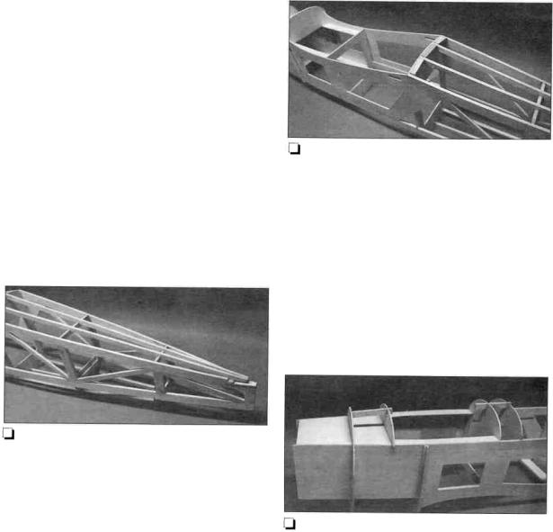
 18. Cut three 1 /4" x 1 /2" x 24" balsa sticks to a length of 19". Glue these top rear stringers to bulkheads E, F and G.
19. Notch the bottom stringers to accept the diecut 1/8" ply tailwheel plate. The correct position for the bracket will allow the 1/4" x 1/2" stringers, added in the next step, to extend 1 /4" below the bottom of the 1/4" x 15/16" side stringers. When satisfied with the fit glue the die-cut plate into position with 6-minute epoxy.
 20. Cut two 1/4" x 1/2" x 30" balsa sticks to a length of 28-1/2". Fit and glue these bottom stringers into position. You will need to notch them at bulkheads F and G. They should extend 1 /4" below the 1/4" x 15/16" side stringers. You can let them extend into the area where the tailwheel plate is mounted if desired.
21. Use leftover 1/4" x 1/2" balsa sticks to frame between the bottom stringers at bulkhead E. Just tack glue them into position at this time as you may need to adjust them when the wing is fitted.
 22. Glue the 1 /4" ply wing hold down plate into place with 6-minute epoxy. Use some leftover 1/4" x 3/8" basswood sticks to reinforce above the ply plate.
23. Roll the fuselage over and glue Bulkheads B-1 and D-1 into place. Bulkhead B-1 is glued 3-1/16" behind Bulkhead B and bulkhead D-1 is glued 2" behind bulkhead D.
 24. Cut and glue the stringers between bulkheads B and B-1 and between bulkheads D and D-1. Use leftover 1/4" x 1/2" balsa sticks.
10
 Loading...