

Page 1

TALNP02 Printed in USA
READ THROUGH THE PRELIMINARY INFORMATION BEFORE YOU START
BUILDING. IT CONTAINS IMPORTANT INSTRUCTIONS, WARNINGS, AND
INFORMATION CONCERNING THE BUILDING AND USE OF THIS MODEL.
© Copyright 2000 V:1.3
Instruction Manual
•Hand-launch sailplane for thermal or slope flying
•Flat wing with ailerons for ultimate maneuverability
•Rugged, lightweight balsa/ply construction
•Optional V-tail version
WARRANTY
Dynaflite guarantees this kit to be free from defects in both material and workmanship at
the date of purchase. This warranty does not cover any component parts damaged by use
or modification. In no case shall Dynaflite’s liability exceed the original cost of the
purchased kit. Further, Dynaflite reserves the right to change or modify this warranty
without notice. In that Dynaflite has no control over the final assembly or material used for
final assembly, no liability shall be assumed nor accepted for any damage resulting from
the use by the user of the final user-assembled product. By the act of using the userassembled product, the user accepts all resulting liability. If the buyer is not prepared
to accept the liability associated with the use of this product, return this kit
immediately in new and unused condition to the place of purchase.
™
™
Page 2

INTRODUCTION ......................................2
PRECAUTIONS ........................................3
PREPARATIONS.......................................3
Required accessories ..................................3
Required building supplies and tools........4
Building notes..............................................4
Types of wood .............................................4
BUILD THE FUSELAGE.............................5
Join the upper fuselage sides ....................5
Finish framing the fuselage........................7
Make the hatch ............................................8
BUILD THE TAIL SURFACES.....................9
Make the stab mount ..................................9
Build the stab ...............................................9
Prepare the stab and fin for joining to the fuse
11
BUILD THE WING ...................................12
Build one wing panel ................................12
Finish the wing panel................................14
Join the wing .............................................17
Mount the wing to the fuselage ...............18
Mount the hatch.........................................19
Mount the stab and fin to the fuselage ...20
FINAL CONSTRUCTION.........................20
Mount the servos ......................................20
Cover your model......................................21
GET YOUR MODEL READY TO FLY .........22
Hinge the ailerons .....................................22
Balance the model.....................................22
Mount your receiver and battery .............23
Set the control throws ..............................23
PREFLIGHT ............................................23
FLYING ..................................................24
Congratulations and thank you for purchasing
the Dynaflite Talon. While the Talon is not
necessarily an advanced glider, it is intended for
modelers with some previous R/C building and
flying experience. Due to its flat wing and
relatively thin airfoil, the Talon is quite
maneuverable and penetrates well, so it is at
home either on the slopes or the breezy planes.
The unique fuselage construction yields an
interesting triangular cross section that builds
rapidly and is pleasing to look at. This
instruction manual also shows you how to build
both the conventional straight-tail version or
the V-tail version. We hope you enjoy building
and flying your Dynaflite Talon!
Your Talon is not a toy, but a sophisticated
working model that functions like a full-size
sailplane.
Because of its performance, if you do not
assemble and operate the Talon correctly, you
could possibly injure yourself or spectators
and damage property.
To make your R/C modeling experience
totally enjoyable, we recommend that
you get assistance with assembly and
your first flights from an experienced,
knowledgeable modeler. You’ll learn faster
and avoid risk to your model before you’re
truly ready to solo. Your local hobby shop has
information about flying clubs in your area
whose membership includes qualified
instructors.
You can also contact the national Academy of
Model Aeronautics (AMA), which has more
than 2,500 chartered clubs across the country.
We recommend you join the AMA which will
provide you with insurance coverage at AMA
club sites and events. AMA Membership is
required at chartered club fields where
qualified flight instructors are available.
Contact the AMA at the address or toll-free
phone number next page.
PROTECT YOUR MODEL,
YOURSELF & OTHERS...
FOLLOW THIS IMPORTANT
SAFETY PRECAUTION
INTRODUCTION
TABLE OF CONTENTS
2
Page 3
Academy of Model Aeronautics
5151 East Memorial Drive
Muncie, IN 47302-9252
Tele. (800) 435-9262
Fax (765) 741-0057
Or via the Internet at:
http://www.modelaircraft.org
1. You must assemble the model according to
the instructions. Do not alter or modify the
model, as doing so may result in an unsafe or
unflyable model. In a few cases the plans and
instructions may differ slightly from the
photos. In those instances the written
instructions are correct.
2. You must take time to build straight, true and
strong.
3. You must properly install the R/C radio
system and other components so that the
model operates properly on the ground and in
the air.
4. You must test the operation of the model
before every flight to ensure that all equipment
is operating, and that the model has remained
structurally sound. Check clevises or other
connectors frequently and replace them if they
show signs of wear or fatigue.
Please inspect all parts carefully before
you start to build! If any parts are missing,
broken or defective, or if you have any
questions about building or flying this
model, please call us at (217) 398-8970
and we’ll be glad to help. If you call for
replacement parts, please look up the part
numbers and the kit identification number
(stamped on the end of the carton) and
have them ready when you call.We can
also be reached by E-Mail at:
productsupport@dynaflite.com
This is a list of the “hardware” items you will
need to complete your kit. Order numbers in
parentheses (OSMG2691) are provided for
your convenience and are recognized by
distributors and hobby shops. GPM is the
Great Planes
®
brand, TOP is the Top Flite
®
brand and HCA is the Hobbico®brand.
❏ 2-Channel Aircraft Radio System with 2
micro servos and mini battery pack (250
mAh)
❏ 1 Roll Top Flite EconoKote
®
covering
❏ 2 Great Planes 24” Flexible Cable
Pushrods (GPMQ3700)
❏ Great Planes Double-Sided Foam Tape
(GPMQ4442)
REQUIRED ACCESSORIES
PREPARATIONS
NOTE: We, as the kit manufacturer, can
provide you with a top quality kit and great
instructions, but ultimately the quality and
flyability of your finished model depends on
how you build it; therefore, we cannot in any
way guarantee the performance of your
completed model and no representations are
expressed or implied as to the performance or
safety of your completed model.
PRECAUTIONS
3
Page 4
These are the building tools and supplies that
you will need to build your Talon. We
recommend Great Planes Pro™ CA and Epoxy
❏ 1 oz. Thin CA (GPMR6002)
❏ 1 oz. Medium CA+ (GPMR6008)
❏ CA Applicator Tips (HCAR3780)
❏ CA Accelerator (GPMR6035)
❏ 30-Minute Pro Epoxy (GPMR6047)
❏ #1 Hobby Knife (HCAR0100)
❏ #11 Blades (Qty. 5 – HCAR0211)
❏ Razor Plane (MASR1510)
❏ Small T-pins (HCAR5100)
❏ Great Planes Plan Protector (GPMR6167)
❏ Electric Drill
❏ Drill Bits: 1/16", 7/64" (or 3/32"), #25 (or
5/32"), 3/16", #12 (or 3/16")
❏ #1 Phillips Screwdriver
❏Top Flite Covering Iron (TOPR2100)
❏ Hot Sock
™
(for your covering iron,
TOPR2175)
❏ Denatured or Isopropyl Alcohol (for epoxy
clean-up)
❏ HobbyLite
™
Balsa Filler (HCAR3401)
❏ Lead/Acid or Silver Solder (GPMR8070)
❏ Bar Sander or Sanding Block and
Sandpaper (coarse, medium grit)
❏ 10-32 Tap
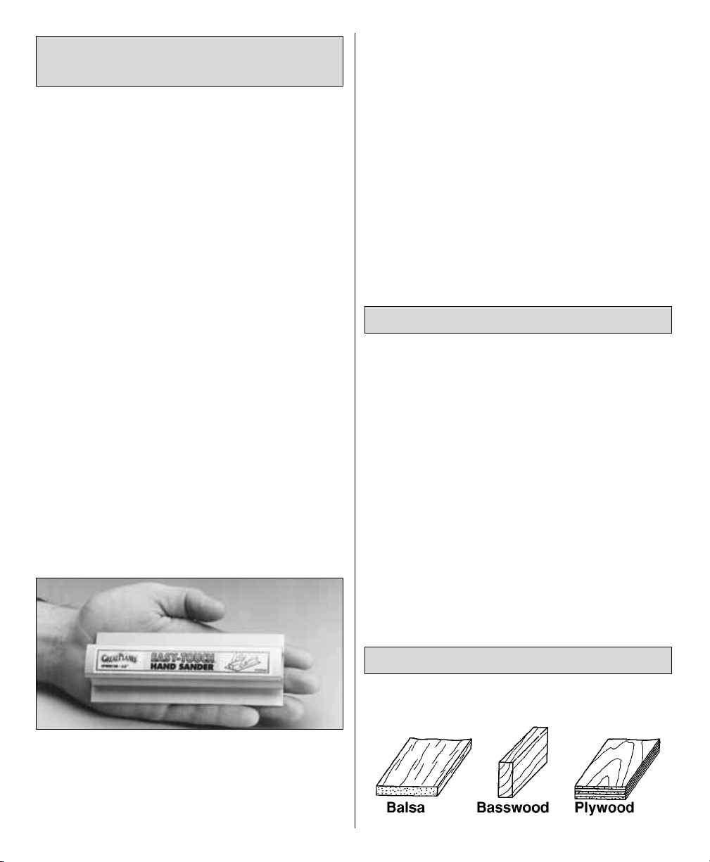
A flat, durable, easy to handle sanding tool is a
necessity for building model airplanes. Great
Planes makes a complete range of Easy-Touch
™
Bar Sanders and replaceable Easy-Touch
Adhesive-backed Sandpaper.
Here’s a complete list of Easy-Touch Bar Sanders
and Adhesive Backed Sandpaper:
5-1/2" Bar Sander (GPMR6169)
11" Bar Sander (GPMR6170)
22" Bar Sander (GPMR6172)
33" Bar Sander (GPMR6174)
44" Bar Sander (GPMR6176)
11" Contour Multi-Sander (GPMR6190)
12' roll of Adhesive-backed 80-grit sandpaper
(GPMR6180)
150-grit (GPMR6183)
220-grit (GPMR6185)
Assortment pack of 5-1/2" strips (GPMR6189)
•When you see the term “test fit” in the
instructions, it means you should first
position the part on the assembly without
using any glue, then slightly modify or
“custom fit” the part as necessary for the
best fit.
•Whenever just “epoxy” is specified you may
use
either
30-minute epoxy
or
6-minute
epoxy. When 30-minute epoxy is specified,
it is highly recommended that you use only
30-minute (or slower) epoxy because you will
need either the working time and/or the
additional strength.
TYPES OF WOOD
BUILDING NOTES
REQUIRED BUILDING
SUPPLIES AND TOOLS
4
Page 5
❏ 1. Unroll the plan sheet. Tightly roll it the other
way so it will lie flat.
❏2. Place the die-cut 3/16" balsa fuse bottom over
the top view of the plan and mark the location of
formers 1 through 6 using a straightedge and a
ballpoint pen.
Note: If some of the parts are difficult to remove
from their die sheets, don’t force them out but
cut around them with a hobby knife and a #11
blade. After you remove the parts, lightly sand
the edges to remove slivers or die-cutting
irregularities. Save some of the larger scraps of
wood as you proceed.
❏ 3. Position the plan so the top view of the fuse
is over a flat building board that you can stick
pins into. Cover the top view of the fuse with
Great Planes Plan Protector or wax paper.
(For clarity, this photo shows the fuse bottom off
the plan, but yours should be pinned to your
building
board over the plan as instructed in this step.)
❏ 4. Accurately position the fuse bottom over its
location on the plan and pin it down only
between formers 2 and 3. Raise the front of the
fuse 1/2" and the rear of the fuse 3/4" using the
1/2" x 3/4" x 2" balsa block cut into two pieces.
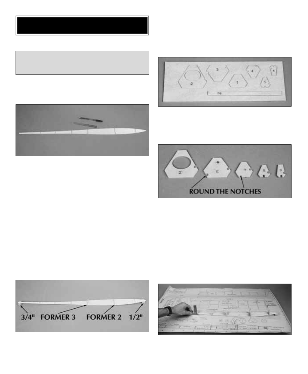
❏ 5. Use a ballpoint pen to label the die-cut 1/8"
plywood formers and dihedral brace (DB) as
indicated in the photo. Remove the parts from the
die sheet.
❏ 6. Drill a 3/16" hole through former 3 at the
punchmark. Use a small, round file or a rotary
tool to round the “V” notches in formers 3
through 6 to accommodate the 1/8" pushrod
guide tube (not included) and the antenna guide
tube (not included).
❏ 7. Drill a 3/16" hole through the center of former
1. After your Talon is completed, this will allow
you to add lead shot to the compartment in the
front of the fuse for ballast or to adjust the C.G.
❏ 8. Lightly spray the fuse bottom with CA
accelerator over the lines indicating the location
of the formers. Making certain the notches in the
JOIN THE UPPER
FUSELAGE SIDES
BUILD THE FUSELAGE
5
Page 6
sides of the formers are on the left side of the
fuse, glue the formers to the fuse bottom with
thin CA. As you proceed, use a small building
square to keep the formers perpendicular to your
building board.
❏9. Position one of the die-cut 3/16" balsa upper
fuse sides over the side view of the fuse plan,
aligning the front where indicated on the plan.
Mark the location of formers 2 and 3 on the fuse
side with a straightedge and a ballpoint pen. This
is now the left fuse side.
❏ 10.Transfer the lines from the left fuse side to
the right fuse side.
❏11. Securely pin the 1/2" x 3/4" x 1" balsa blocks
at the front and back of the fuse to the plan.
Making sure the fuse remains aligned with the
plan, pin the front and back of the fuse bottom to
the blocks.
❏ 12. Position both upper fuse sides on the fuse
assembly, aligning the marks you made with
formers 2 and 3.
❏ 13. Temporarily hold the upper fuse sides to
formers 2 and 3 with T-pins. Pull the aft end of the
upper fuse sides to formers 5 and 6 and check
alignment. Adjust the position of the upper fuse
sides on formers 2 and 3 until they align near the
aft end when you pull them to formers 5 and 6.
❏ 14. When you have achieved the alignment
described in the preceding step, use thin or
medium CA to glue the upper fuse sides only to
formers 2 and 3.
❏15. Carefully checking alignment as you
proceed,
use thin or medium CA to glue the upper fuse
sides to formers 4, 5 and 6.
❏ 16. Pull the upper fuse sides to each other and
to the fuse bottom. Use medium CA to glue the
upper fuse sides to the fuse bottom and to former
1. Refrain from gluing the fuse to the balsa block.
But, if you do, it’s no problem because you can
just break the balsa block free and sand later.
❏ 17. From the 1/8" x 1/4" x 24" balsa stick, cut
three 3/4" long pieces and glue them together to
make the tail block. Cut a 1/8" round notch in
one side of the tail block to accommodate the
antenna guide tube.
6
Page 7
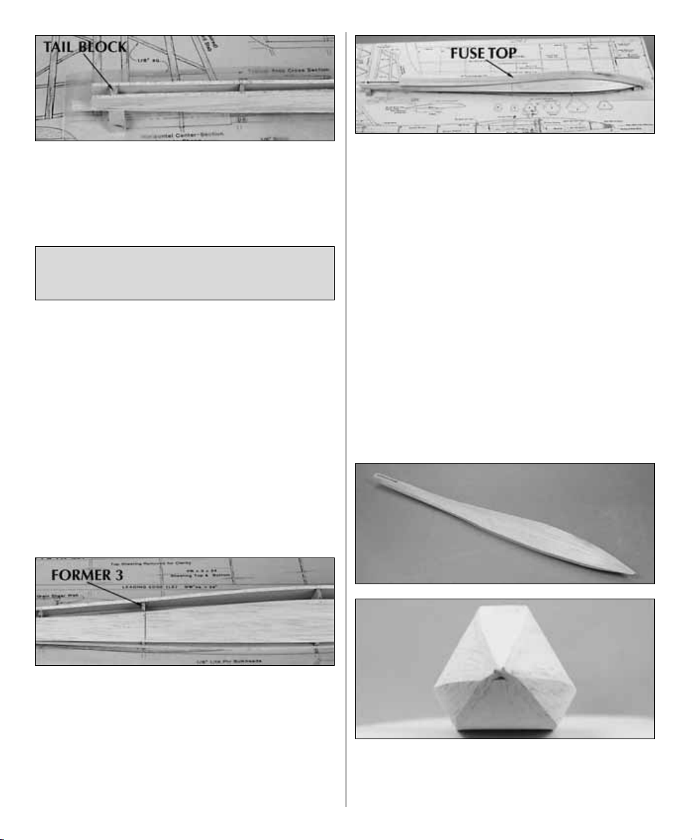
❏ 18. Position the tail block between the upper
fuse sides 4" aft of former 6. Make sure the notch
in the tail block is on the left side and glue it
in place.
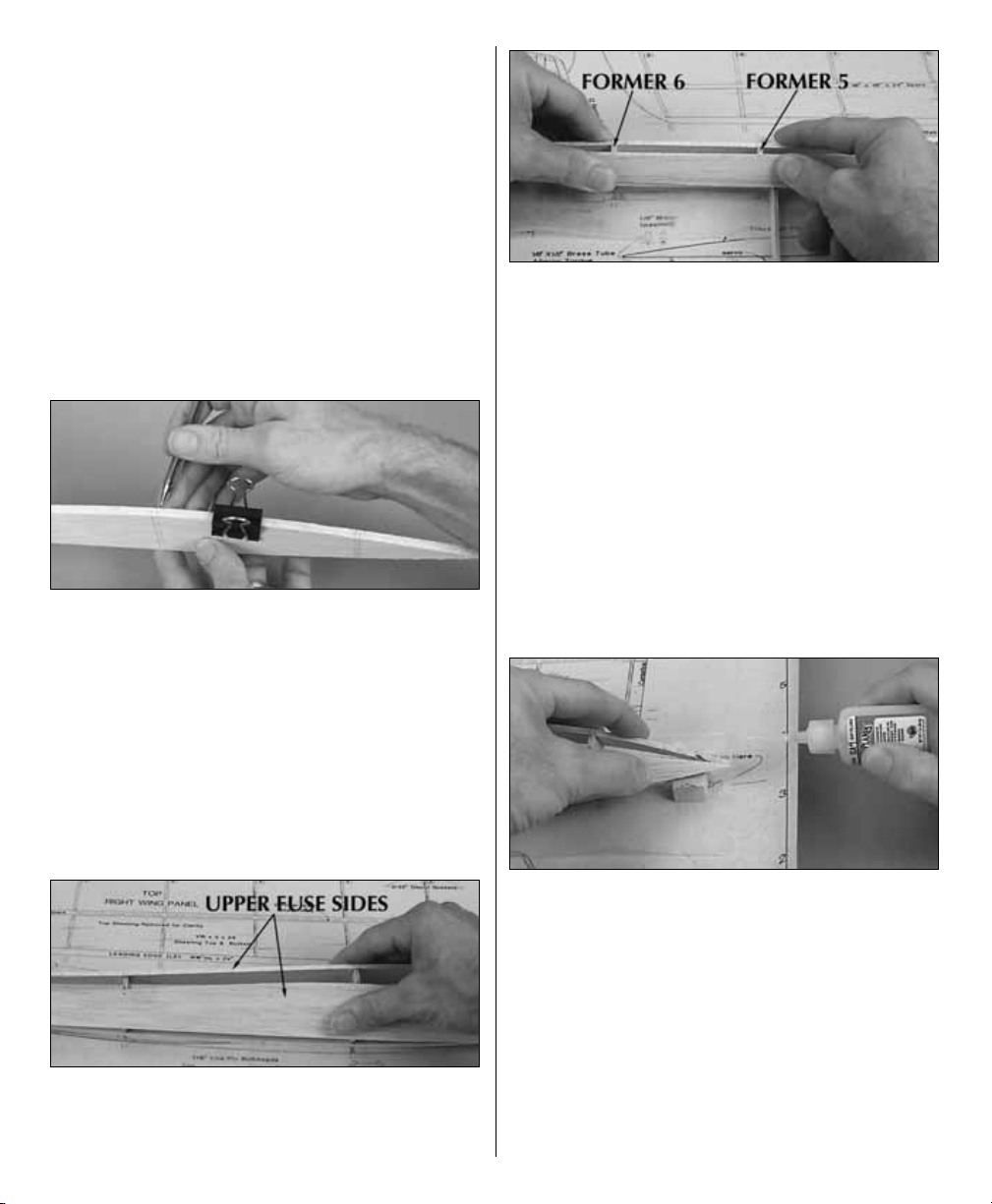
❏ 1. Cut the outer guide tube from a Great Planes
24" Flexible Cable Pushrod (not included with this kit,
GPMQ3700) to a length of 17" to be used for the
elevator. Roughen the outside of the guide tube with
sandpaper so glue will stick. Slide the pushrod
through the bottom holes in formers 3 through 6 as
shown in the side view of the fuse plan.
❏ 2. Roughen the outer guide tube from an
additional Great Planes 24" Flexible Cable
Pushrod kit and slide it through the holes in the
sides of formers 2 through 6. This is the antenna
guide tube.
❏3. Glue both guide tubes in position with medium
CA.
❏4. Use a straightedge and a ballpoint pen to
mark
the front edge of former 3 on both upper fuse
sides.
❏ 5. Use a razor plane and/or a bar sander and
80-grit sandpaper to sand the top edge of the
upper fuse sides as shown in the cross section
drawings on the plan. The top edges of the upper
fuse sides must be even with the tops of the
formers to accommodate the fuse top.
❏6. Glue the 1/8" x 1-1/4" x 30" balsa fuse top to
the fuse with medium or thick CA. The aft edge of
the fuse top should extend 1/2" aft of former 6.
❏ 7. Use a hemostat or small needle nose pliers
to remove the T-pins from the fuse bottom that are
holding it to your building board. You should be
able to reach the T-pins through the space
between the upper fuse sides and the fuse
bottom.
Remove the fuse from your building board.
❏8. Trim the edges of the upper fuse sides and the
fuse bottom even with the formers to accommodate
the lower fuse sides, the same way you did for the
fuse top.
❏ 9. Glue one, then the other die-cut 1/8" balsa
lower fuse side to the fuse. Handle the fuse
carefully as you position so you do not build in any
twist
to the fuselage.
❏ 10. Use your razor plane and/or your bar
sander to sand the lower fuse sides even with the
upper fuse sides and the fuse bottom. Trim all
sheeting even with the tail block.
FINISH FRAMING
THE FUSELAGE
7
Page 8
❏11. Cut the front of the fuse until the 1/2" x 1/2" x
1/2" hardwood nose block will fit. Glue the nose
block to the fuse, then carve and sand it to the
shape shown on the plan. Note that the grain
direction of the nose block runs parallel with the
length of the fuse.
❏ 12. Use your bar sander and progressively
finer grades of sandpaper to round the edges of
the fuse as shown in the cross section drawings
on the plan.
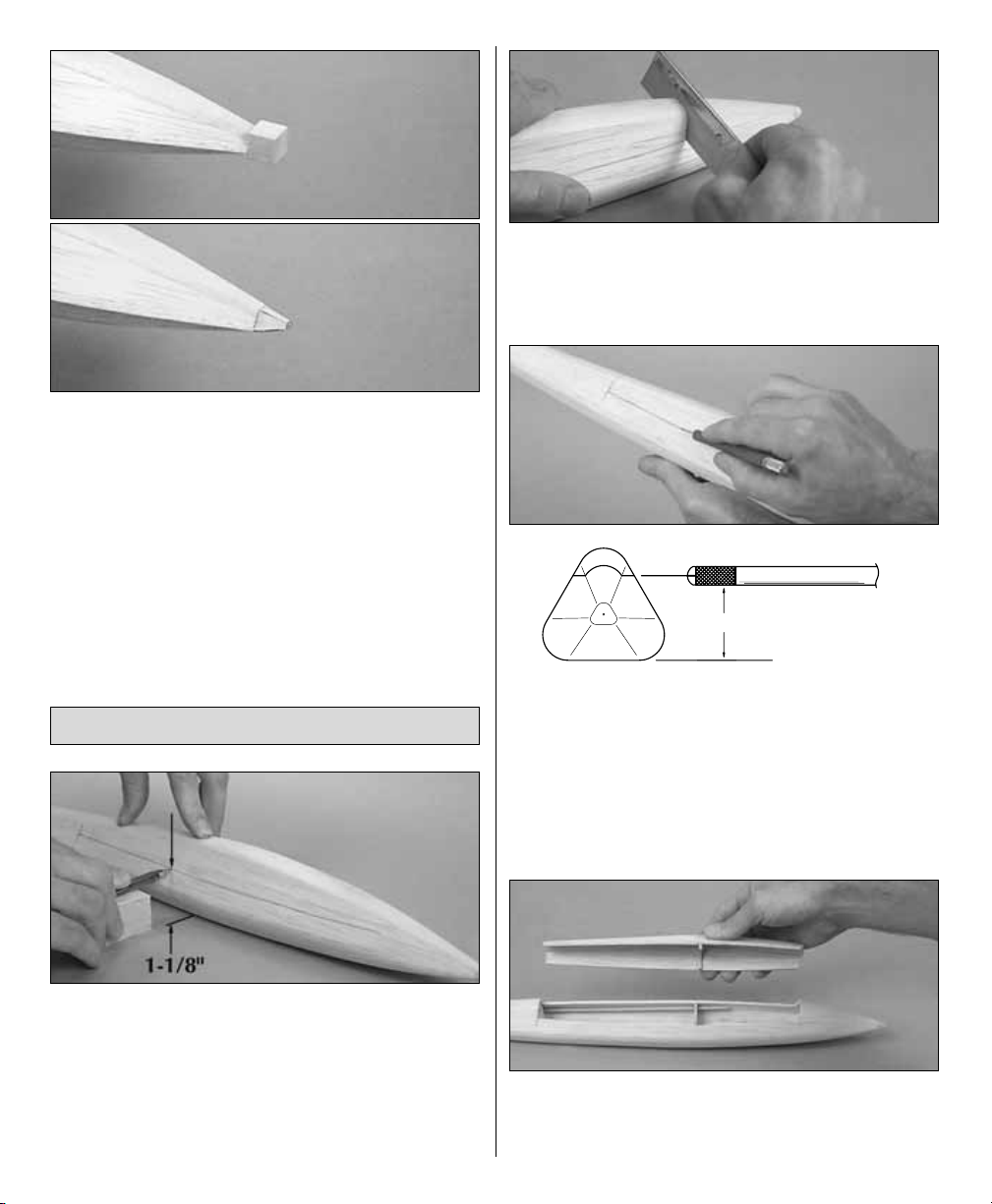
❏ 1. Use a balsa block or something similar to
support a ballpoint pen so the tip will be 1-1/8"
above your building table. Mark the bottom of the
hatch on both sides of the fuse extending from
the lines you marked earlier 11" forward. As you
proceed, press down on the fuselage over the
area
where the bottom is flat as shown in the photo.
❏2. Use a razor saw to cut the aft end of the hatch
along the lines you previously marked. Cut the
front of the hatch at an angle 11" from the aft end
of the hatch.
❏ 3. Use a fresh #11 blade to cut the bottom of
the hatch along the lines you marked on both
sides of the fuselage. Note how the knife in the
photo is inserted at an angle, allowing the tip of
the blade to trail behind. This provides more
stability, allowing you to steer the blade, not the
wood grain. Also note that the cut should be
parallel with the bottom of the fuse.
❏ 4. Use a fine razor saw to cut former 2 as
shown in the cross section on the plan so you can
remove the hatch.
Neato!
MAKE THE HATCH
8
Cut parallel with the fuse bottom.
Page 9

❏ 1. From the 1/8" x 3/4" x 8" balsa stick, cut two
4" long stab mounts.
❏ 2. Cut a 5/32"
half-round
groove 2-1/4" from
one end of both stab mounts as shown on the
cross section of the plan. As you can see on the
plan, when joined together, the stab mounts will
hold the stab joiner wire in position. Hint: Use a
5/32" brass tube sharpened at one end to cut the
hole. Pinch the two stab mounts together and
twist the brass tube as you push it through. As
you proceed, use a small square to help you
guide the tube straight through.
❏3. Cut notches in both stab mounts to
accommodate
the horn on the joiner wire. Round both ends of the
notches (use your sharpened brass tube for the
ends of the notches).
❏4. Use steel wool, sandpaper or a wire brush to
remove corrosion and clean the solder joint
holding the horn to pre-bent stab joiner wire. If
necessary, use a small file to true up the solder
joint so both brass bushings can slide up close to
the horn.
❏5. Test fit the joiner wire between the stab mounts.
Make sure you have made your notches wide
enough and long enough so the horn does not
interfere and so you can get enough elevator throw.
You may build either a conventional
straight-tail
stab and fin or a
V-tail
stab, whichever you prefer.
The instructions show you how to build both
versions. Most of the photos show the
conventional tail, but there are photos of the Vtail where necessary.
❏ 1. Position the plan so the stab is over your
building board, then cover it with Great Planes
Plan Protector or wax paper.
❏ ❏ 2. Pin the stab mount/joiner wire assembly
over the location shown on the plan so the left
edge of the balsa stab mount is 1/16" from the
edge of the stab drawing.
BUILD THE STAB
MAKE THE STAB MOUNT
BUILD THE TAIL SURFACES
9
Page 10

❏ ❏3. Note the location of the
arm
portion of
the
joiner wire. This determines the true location of
the 1/8" x 1/8" balsa
rib
—not necessarily where it
is shown on the plan.
(You can see in the photo
how the rib on our model needed to be moved
inward a bit).
Cut the rib from a 1/8" x 1/8" x 24"
balsa stick and pin it to the plan so it is contacting
the arm of the joiner wire.
❏ ❏4. Remove the stab mount/joiner wire
assembly
from the plan and finish building the stab using
the remainder of the 1/8" x 1/4" x 24" balsa stick
and an 1/8" x 1/8" x 24" balsa stick.
❏ ❏ 5. Remove the assembly from the plan and
carefully sand both sides flat, smooth and even.
Be careful not to weaken the structure by sanding
it too thin. Round the tips, LE and TE.
❏ ❏ 6. Cut a stab spar from the 1/16" x 1/4" x
36" balsa stick, then glue it to one side of the stab
where shown on the plan. Turn the stab half over
and cut an 1/8" notch in the 1/8" x 1/8"
root rib
to
accommodate the elevator joiner wire.
❏ ❏ 7. Glue an additional 1/16" x 1/4" balsa stab
spar to the other side of the stab the same as the
first. Use the remainder of your 1/8" x 1/8" x 24"
balsa stick to make the rib caps that fit on the
front and back of the stab spars on the top and
bottom of the stab. Blend the rib caps and the tip
of both stab spars to the stab by sanding.
❏8. Return to step 2 and build the other stab half
the same way. When you position the edge of the
stab mount/joiner wire 1/16" from the end of the
stab, you’ll have to turn it around so you get the
correct spacing for the other side of the joiner.
10
1/16" x 1/4" Stab Spars
Trim
1/8" Notch
1/8" x 1/8" Rib Caps
Page 11

❏ 9. If you’re building the conventional straight-
tail, build the fin using the 1/8" x 1/8" balsa sticks
and the 1/8" x 1/4" balsa sticks leftover from
building the stab halves. Use leftover 1/8" balsa to
make the tip of the fin.
❏ 1. If you’re building the V-tail version, bend the
joiner wire as shown on the plan. When you bend
the wire, clamp your pliers over the brass bearing
tube next to the horn. Hold the joiner wire over
the plan to make sure you have bent both sides
the same.
❏2. Use sandpaper to roughen both brass
bearing
tubes on the joiner wire so glue will adhere. While
you’re at it, roughen the joiner wire where it will
be glued to the elevators.
❏3. Carefully add a small drop of oil to the joiner
wire on both sides of the horn to lubricate the
bearing tubes. Refrain from getting oil on the
outside of the bearing tubes.
❏ 4. Glue the balsa stab mounts together with
the joiner wire in between. Make sure you have
the joiner wire facing the right way and make
sure
you glue the bearing tubes to the mounts,
but
refrain from getting glue inside the bearing tubes.
❏ 5. Sand the top of the stab mount to the airfoil
shape shown on the plan.
❏ 6. Test fit both stab halves to the joiner wire
and the stab mount. Position the stab halves so
they are centered on the stab mount and are even
with each other. View the stab from the rear and
make sure they are both in the same plane. If
necessary, remove the stab halves and use pliers
to
tweak
the joiner wire so both stabs are even.
PREPARE THE STAB AND FIN
FOR JOINING TO THE FUSE
11
Page 12

❏7. Remove the stab halves from the joiner wire.
Solder a metal clevis to the braided wire
elevator
pushrod cable that came in your pushrod kit.
❏8. Connect the clevis to the bottom hole on the
joiner wire. Slip the cable through the elevator
pushrod guide tube in the fuse and position but
do not glue the stab mount on the fuse as
shown in the photo and on the plan. Move the
cable back and forth to actuate the joiner wire.
Make adjustments as necessary so the system
operates smoothly.
That’s about all we can do on the tail and the fuse
until we get the wing built. Set the stab and fuse
aside for now.
Do the right one first so yours looks like the
photos.
❏ ❏ 1. Use a ballpoint pen to draw a guideline
3/32" from the bottom of one of the 5/16" x 1-1/4"
x 24" balsa ailerons. This guideline indicates the
desired thickness of the trailing edge of the
aileron. As shown in the photo, the guideline can
be most easily drawn by laying your pen and the
aileron on your workbench. You may have to raise
the aileron off your workbench to make the
guideline at the correct height. With the pen we
used, it happened that one of the included 1/16"
balsa sheets worked perfectly for this.
❏ ❏2. Using the line you drew as a guide,
carefully
shape the aileron to the cross section shown on
the wing plan. We prefer a razor plane followed
by
a bar sander with 80-grit sandpaper for this
job.
How’d you do? It wasn’t so bad, was it?
❏3. Before we get started on the
real
wing
construction,
mark and shape the other aileron the same way.
❏ ❏ 4. Arrange the plan so the right wing panel
is over your building board and cover it with
Great Planes Plan Protector. Note: If this is your
second wing panel, make sure you are building
the left one.
❏ ❏ 5. Use a fresh #11 blade and a straightedge
to true one edge of a 1/16" x 3" x 24" balsa sheet.
Trim the other edge of the sheet as indicated in
the sketch. From now on this sheet will be called
the bottom leading edge skin.
❏ ❏ 6. Glue a 1/8" x 1/4" x 24" balsa spar to the
top of the bottom leading edge skin along the
edge you trued (the aft edge).
❏ ❏7. Accurately align the root and the aft edge of
the bottom leading edge skin with the plan and pin
it down.
BUILD ONE WING PANEL
BUILD THE WING
12
2-1/2"
Root
True
Trim
Tip
1-7/8"
Page 13

❏ ❏ 8. Label both sets of die-cut 3/32" wing ribs
as shown in the sketch and carefully remove them
from their die sheets. If any of the ribs are difficult to
remove, cut around them first. Remove any diecutting irregularities or slivers with a hobby knife or
sandpaper.
❏ ❏9. Place ribs 3 through 9 on the bottom spar.
If necessary, trim the notch in rib 9 so it will fit the
bottom spar at the angle on the plan.
❏ ❏ 10. Cut the bottom center section
sheeting
from a 1/16" x 3" x 24" balsa sheet (if you’re
building your second wing panel—the left one—
use the remainder of the same 1/16" x 3" x 24"
piece you used when you built the right wing
panel). Accurately align the edge of the sheet with
the end of the wing where shown on the plan and
pin it in position. Place ribs 1 & 2 over the
sheeting
where shown on the plan.
❏ ❏11. Place the 1/8" x 3/8" x 24" balsa sub
trailing
edge (TE) up against the ribs over its location on
the plan. Pin a straightedge to the plan tightly up
against the sub TE to hold it in position. Trim any ribs
as necessary to make sure the sub TE will remain
straight.
❏ ❏ 12. One at a time, glue ribs 3 through 9 to
the sub trailing edge and the bottom spar. As you
proceed, make certain the sub TE and the ribs
are contacting your building board.
❏ ❏ 13. Use a straightedge to align ribs 1 & 2
with the
tick marks
on the plan. Then glue them to
the bottom center section sheeting, the bottom
spar and the sub trailing edge. Glue the center
section sheeting to the leading edge skin and the
sub trailing edge.
❏ ❏14. Using the same 1/16" sheet you used for
the bottom center section sheeting, cut four
shear webs to fit between ribs 2 through 6. Test
fit, then glue the shear webs between the ribs.
Make certain that the shear webs are the correct
height so they will contact the top spar, yet allow
the top spar to fully seat in the notches of the
ribs.
❏ ❏15. Test fit, then glue a 1/18" x 1/4" x 24" top
spar to the ribs and the shear webs. Note that the
top of the spar should be even with the tops of
ribs 1 and 2 to accommodate the top center
section sheeting.
1
13
4
23
87
5
9
6
Page 14

❏ ❏16. One rib at a time, simultaneously
lift up
on the bottom LE skin at each rib as you
push
down
on the rib. Add a few drops of thin CA to
glue the skin to the rib. Hint: Use a thin metal
ruler or something similar as a
pry bar
to lift the
skin to the rib.
❏ ❏17. Trim another 1/16" x 3" x 24" balsa sheet as
described in step 5 to make a top leading edge
skin.
❏ ❏ 18. Reposition any T-pins in the bottom spar
that will be concealed when you position the top
leading edge skin and the top center section
sheeting. Apply a bead of medium or thick CA to
the top spar only and glue the top leading edge
skin in position.
(For clarity, the wing panel is not shown on the
building board in this photo, but yours should
still be pinned down).
❏ ❏19. Glue a die-cut 3/32" balsa gusset to both
sides of rib 2 and the sub trailing edge. Glue an
additional gusset to rib 9 and the sub trailing
edge. This gusset is not shown on the plan and
you’ll have to trim it to fit.
❏ ❏20. Sheet the top of the center section using
the same 1/16" x 3" balsa sheet you used for the
shear webs and the bottom center section.
❏ ❏ 21. Lightly wet the top leading edge skin
with Windex
™
or water, then remove the T-pins
and lift the wing panel from your building board.
❏ ❏ 22. Use thin CA to glue the top skin to the
ribs. Do one rib at a time holding the top skin
down until the glue hardens.
❏ ❏ 1. Use a razor plane followed by a bar
sander with 80-grit sandpaper to trim both LE
skins even with the front of the ribs.
❏ ❏ 2. Trim the end of the wing skins and the
spars even with rib 9.
❏ ❏3. Glue the 5/16" x 5/16" x 24" balsa leading
edge to the wing. We did it one half at a time by
applying a bead of medium CA to the LE skins
from the middle of the wing outward, then
holding the LE in position for a few moments
until the CA cures. Lift the other end of the LE
from the wing and apply another bead of CA to
the skins from the middle of the wing outward in
the other direction and hold the LE to the wing.
Another method would be to use aliphatic resin
such as Great Planes Pro and hold the LE to the
FINISH THE WING PANEL
14
Page 15

wing with masking tape until the glue dries
(about an hour should be sufficient).
❏ ❏ 4. Use your razor plane followed by a bar
sander with 80-grit sandpaper to blend the LE to
the top and bottom skins. Do not round the LE
until you are instructed to do so after you join the
two halves together.
❏ ❏ 5. Glue a shaped triangular balsa wing tip
block to the end of the wing. Note that the flat
side of the tip block is on the bottom of the wing
so the tip curves downward. Carve, then sand
the wing tip block to match the shape of the wing
and the plan.
❏ ❏6. Cut 2-1/2" from one of the ailerons you
shaped
earlier to make an aileron torque rod block. Cut
a 5/32" groove through the center of the leading
edge of the block to accommodate the nylon
bearing tube on the right aileron torque rod.
Hint: Use a 5/32" brass tube sharpened at one end
to cut the groove.
❏ ❏ 7. Test fit the pre-bent wire right aileron
torque rod (or the left aileron torque rod if
this is your second time through and you are
building the left wing panel) in the torque rod
block. If necessary, enlarge the groove you cut so
the torque rod will fit all the way in. Cut a notch in
the bottom of the torque rod block to allow for
control throw.
❏ ❏8. Cut a notch in the sub trailing edge of the
wing panel (the same as the notch in the torque
rod block) to allow for control throw. Roughen the
nylon bearing tube on the aileron torque rod with
coarse sandpaper. Apply a dab of petroleum jelly
(not marmalade)
to the ends of the bearing tube.
Use thick or medium CA to simultaneously glue
the bearing tube in the torque block and glue the
torque block to the sub trailing edge of the wing.
Note that the bottom of the torque block should
be even with the bottom of the wing.
❏ ❏ 9. Use a bar sander with 80-grit sandpaper
to sand the end of the wing square and even.
❏ ❏ 10. Trim the tip of the aileron to match the
angle of the wing tip. Test fit the aileron to the
wing. If necessary, glue leftover balsa to the tips
of the aileron to achieve adequate spacing
15
Page 16

between the tips of the aileron and the wing. We
recommend a 1/16" gap at both ends.
❏ ❏11. Cut a groove and drill a 7/64" (or 3/32")
hole
in the leading edge of the aileron to accommodate
the aileron torque rod. Test fit the aileron to the
wing.
❏ ❏12. Cut three 1/8" x 5/16" x 1" hinge blocks
from leftover 1/8" balsa and glue them to the front
of the sub trailing edge where the hinges are
shown on the plan. The hinge blocks are not
shown on the plan but you can see two of them
in the photo.
❏ ❏13. Mark the location of the hinges on the wing
and the aileron, then cut the hinge slots with a
#11 blade.
❏ ❏14. Cut three hinges from the CA hinge
strip
and test fit the aileron to the wing with the
hinges.
❏ ❏ 15. If necessary, shape the TE of the wing tip
and the top of the sub trailing edge to match
the aileron.
❏ ❏ 16. Remove the aileron from the wing. Use
a razor plane or a hobby knife followed by a bar
sander with 80-grit sandpaper to shape the
leading edge of the aileron to a “V” to allow for
control movement.
❏ ❏ 17. Temporarily join the aileron to the wing.
Operate the aileron by moving the aileron torque
rod back and forth. Make sure you have enough
throw and make sure everything operates
smoothly. Make adjustments as necessary.
That’s about all we can do on this wing until we
join the other wing, so return to step 4 on page
12 and build the Left wing panel. Make sure you
build a LEFT wing panel not a right wing panel!
You may build your wing
flat
or with dihedral.
If you build the wing flat your Talon will have
more maneuverability. If you build your wing
with dihedral your Talon will have more
stability. The wing joiner included with the kit is
for a flat wing. If you wish to build in dihedral,
make your own dihedral brace from 1/8"
plywood (not supplied) using the sketch on
page 24 and raise both tips 3/8" from your
workbench when it’s time to join the wing.
JOIN THE WING
16
CUT HINGE SLOT
WITH HOBBY KNIFE
AND #11 BLADE
Page 17

❏ 1. Cut a 1/8" notch in rib 1 of both wing panels
between the top and bottom spar to
accommodate the die-cut 1/8" plywood wing
joiner (or your homemade joiner if you are
building in dihedral). Test fit the joiner in one wing
half, then the other. Sand the joiner and adjust the
notch in the ribs as necessary for a good fit.
Perform step 2 only if you are building your
wing f
lat.
❏ 2. Test join the wing halves with the wing
joiner. Lay your wing flat on your workbench so
the aileron torque rods are over the edge. If
necessary, use your bar sander and 80-grit
sandpaper to sand the ends of the wing for a
good fit.
Perform step 3 only if you are building your
wing with
dihedral.
❏3. Test join your wing halves with your
homemade
wing joiner. Use your bar sander to sand the ends of
the wing as necessary so they will fit at the
correct angle.
❏ 4. Use a piece of wire or something similar to
thoroughly apply 30-minute epoxy to the spars
inside one wing half and to the top and bottom
edges of one half of the wing joiner. Slide the
joiner into the wing between the spars. Be certain
the joiner is centered between the spars. Wipe
away excess epoxy and allow the assembly
to cure.
❏5. Lay a piece of Great Planes Plan Protector on
your workbench. After the epoxy from the
previous step has fully cured, apply 30-minute
epoxy to the spars inside the other wing half, the
top and bottom of the other end of the joiner and
to the sheeting on the end of both wing halves.
Proceed quickly to the next step.
❏6. Join both wing halves and wipe away excess
epoxy. Lay your wing on the plan protector on
your workbench. If you are building your wing
flat, place weights on top of your wing to keep it
from moving and to hold it down. If you are
building your wing with dihedral, use balsa
blocks or something similar to raise both wing
tips 3/8". Make sure the trailing and leading edges
align. Do not disturb your wing until the epoxy
has fully cured.
❏7. Lightly sand the center section of your wing to
blend the two halves together. Finish rounding the
leading edge as shown in the cross section on
the plan.
❏8. Glue the 1" x 14" strip of glass cloth over the
seam between the two wing halves. You may use
1/8" Notch
17
Page 18

CA but we prefer 30-minute epoxy. Whatever
adhesive you use, just make sure the cloth is
thoroughly saturated and is securely bonded to the
sheeting.
❏1. Cut both aileron torque rods to a length of
5/8".
❏ 2. Round one end of the 3/16" x 1-1/2" wing
dowel. Test fit the dowel into the hole you drilled
in former 3. If necessary, use a round wood file or
a small tube wrapped with sandpaper to enlarge
the hole so the dowel fits easily but snugly.
❏3. Cut a 3/16" notch in the center of the TE of the
wing to accommodate the dowel. The aft,
rounded end of the dowel should protrude from
the TE of the wing 5/16".
❏4. Fit the wing to the fuselage using the dowel.
Make adjustments where necessary for a good fit.
❏5. With the wing on the fuselage, apply a small
amount of epoxy over the dowel to glue it to the
wing. For additional strength, add some Great
Planes Milled Fiberglass to the epoxy. Be careful
so you don’t glue the dowel to the fuse.
❏ 6. After the epoxy from the previous step has
fully cured, remove the wing. Glue the dowel to
the bottom of the wing with more epoxy.
❏ 7. Similar to the way you did the trailing edge
of the wing, notch the leading edge of the wing to
accommodate the 3/8" x 1/2" x 1-3/4" wing bolt
block when it is in position against the aft edge
of former 2. Test fit the wing with the wing bolt
block.
❏ 8. Remove the wing bolt block and drill a #25
(or 5/32") hole through the block as shown on the
plan. If you have access to one, use a drill press
to keep the hole on center as you drill, or just
proceed carefully and use your
eagle eye
to drill
straight through.
❏ 9. Cut 11/16" from the top of the wing bolt
block. You now have a bottom and a top wing
bolt block.
MOUNT THE WING TO
THE FUSE
18
5/8"
Aileron T orque Rod
Page 19

❏10. Securely glue the bottom wing bolt block to
the aft edge of former 2 and the bottom of the
fuse. Enlarge the hole in the bottom wing bolt
block and drill through the bottom of the fuse
with a #12 (or 3/16") drill bit.
❏ 11. Tap threads into the top wing bolt block with
a 10-24 tap. Coat the threads with thin CA. Allow to
fully cure (you may use a little CA accelerator), then
re-tap the threads. Coat with thin CA and re-tap
once more.
❏12. Secure the top wing bolt block to the
bottom
wing bolt block with the 10-32 x 2" nylon wing
bolt. Position the wing on the fuselage with the
top wing bolt block in the notch in the leading
edge.
❏ 13. Check the wing alignment by accurately
measuring the distance between both wing tips and
the aft end of the fuse. If necessary, trim the notch
in the LE of the wing for the wing bolt block and
shift the wing until the distances between the tips
and the aft end of the fuse are equalized.
❏14. Securely glue the wing to the top wing bolt
with epoxy. For additional strength, add Milled
Fiberglass Fibers to the epoxy. Build up a small
fillet of epoxy around the top wing bolt block, but
make sure you don’t glue it to the bottom wing
bolt block. Place a weight on top of the wing to
hold it down until the epoxy fully cures.
❏15. Cut a small, round hole in the fuse bottom to
countersink
the head of the nylon wing bolt. Hint:
Use a 13/32" brass tube sharpened at one end to cut
the hole.
Refer to this photo while you mount the hatch to
the wing.
❏ 1. Cut the end of the nylon wing bolt so it is
even with the top of the top wing bolt block.
❏ 2. With the wing bolted to the fuselage, little by
little carefully trim the hatch until it fits the wing.
Proceed slowly and frequently test fit the hatch as
you proceed.
❏3. Use thin or medium CA to carefully glue the
hatch to the wing only. Remove the wing.
❏ 4. Use leftover 1/8" balsa to fill the space
between the bottom of the wing near the LE and
the fuse. Glue the leftover balsa pieces to the
wing
and shape them to fit the wing saddle on the fuse.
❏ 5. Use lightweight, sandable balsa filler where
needed to blend the hatch to the wing. Do not
build up a fillet, but use just enough filler to fill
any gaps between the hatch and the wing. Then,
yours will look as nice as ours (almost!)
MOUNT THE HATCH
19
Page 20

These following instructions apply to you V-tail
builders, too.
❏ 1. Temporarily position the stab mount on the
fuse with both stab halves. With the wing bolted
to the fuse, view the model from the rear to make
sure the stab aligns horizontally with the wing
(it’ll be a little trickier to see the V-tail stab
alignment with the wing, but it’s the same idea).
If necessary, trim the stab saddle of the fuse to
bring the stab into alignment with the wing.
❏ 2. After you have achieved the alignment
described above, connect the elevator cable to
the elevator joiner wire. Route the cable through
the guide tube and securely glue the stab mount
to the fuse with 30-minute epoxy. Hold the stab
mount in position with T-pins until the epoxy is
fully cured.
❏3. Sand the end of the stab mount and the fuse
sheeting even with former 6.
❏ 4. If you’re building the straight-tail, trim the
bottom of the fin to fit the fuse and stab mount.
Glue the fin in position. Make the small fin filler
from leftover 1/8" balsa. Glue the fin filler to the
front of the fin and the fuse top. Blend to the fin
by sanding.
Refer to this photo while you mount your aileron
servo in the wing.
❏1. Cut a hole through the bottom wing sheeting
to accommodate your aileron servo. Test fit your
servo.
❏2. Make two servo mount plates from leftover
1/8" plywood. Glue the servo mount plates to the
bottom of the wing. Mount your aileron servo to
the plates with the wood screws that came with
your servo.
❏ 3. Connect the aileron servo to the aileron
torque rods with the nylon swivel and swivel
clevis and two .074" x 4" wire pushrods. Cut the
pushrods to the correct length and connect them
to the servo horn with a Z-bend. If necessary,
enlarge the holes in your servo horn with a hobby
knife or a #48 drill.
Refer to this photo while you mount your elevator
servo.
❏4. Make a one arm servo horn for your elevator
servo by cutting off the unused arms. Connect the
MOUNT THE SERVOS
FINAL CONSTRUCTION
MOUNT THE STAB AND
FIN TO THE FUSE
20
Page 21

servo horn to your elevator servo and secure it
with the screw.
❏ 5. Position your elevator servo in the fuselage.
Make servo holders for the elevator servo as
shown on the plan from leftover 1/8" x 1/8" balsa
and glue them to the fuse bottom.
❏ 6. Cut the elevator cable and the guide tube to
the correct length, then solder a brass threaded
coupler to the cable. Connect the threaded
coupler to the elevator servo with a nylon clevis.
❏ 7. Mount the elevator servo to the fuse bottom
with Great Planes Double-Sided Foam Tape
(GPMQ4442, not included). For additional security,
before mounting the servo, some modelers prefer
to seal the wood grain in the area where the servo
is to be mounted with a light coat of epoxy. After the
epoxy cures, wipe with alcohol, then mount your
elevator servo with the foam tape.
❏8. Secure the front end of the guide tube to the
fuselage with a piece of leftover balsa.
❏ 1. Fill dents, scratches or low spots on your
model with lightweight, sandable balsa filler. You
can eliminate smaller dents or scratches by wetting
the area which will cause the balsa to swell. Sand
when dry.
❏ 2. Sand your entire model, finishing with 320
or 400-grit sandpaper.
❏3. Use compressed air or a paint brush to
remove
balsa dust.
❏ 4. Following the covering sequence below,
cover your model with a low heat iron-on
covering such as Top Flite EconoKote film.
Regular iron-on films intended for larger models
may shrink too much, damaging or warping your
structure.
Fuse covering sequence
Fuse bottom
One fuse side, then the other
Vertical fin (if you’ve built the straight-tail
version)
Sides of stab mount
Fuse top and stab mount
❏5. After you cover the fuse, glue the stab halves
to the joiner wire with 30-minute epoxy. Before
the epoxy cures, make sure the ends of the stab
halves align with the stab mount. Wipe away
excess epoxy before it cures.
❏ 6. Cover the top and bottom of one stab half,
then the other.
Wing covering sequence
Hatch sides, then top
Bottom, then top of one wing panel
Bottom, then top of other wing panel
Ailerons
❏ ❏ 1. Use your hobby knife and a sharp #11
blade to remove a small strip of covering from the
hinge slots of one of the ailerons and the
matching half of the wing.
HINGE THE AILERONS
GET YOUR MODEL READY
TO FLY
Follow these instructions. Most importantly, do
not cover the stabilizer halves until after you
have glued them to the joiner wire on the fuse.
The instructions in this section provide the correct
sequence.
COVER YOUR MODEL WITH TOP
FLITE
®
ECONOKOTE®FILM
21
CUT THE COVERING
AWAY FROM THE SLOT
Page 22

❏ ❏2. Join the aileron to the wing with the
hinges.
If you cannot get the hinges to remain centered,
stick a pin through the center of the hinges and
rejoin the aileron to the wing. Remove the pins
after you join the aileron to the wing.
❏ ❏3. Make sure you have a small gap between
the aileron and the wing so you do not
inadvertently glue them together.
❏ ❏ 4. Carefully apply three drops of thin CA to
both sides of the hinges. Use pieces of paper
towel to absorb excess CA before it cures.
Do not use accelerator on any of the
hinges.
Do not glue the hinges with anything other
than thin CA and do not attempt to glue
one half of the hinge at a time with medium
or thick CA. They will not be secure and the
controls could separate while the model
is flying.
❏ ❏5. Let the CA fully cure, then carefully move
the aileron up and down several times to break it
in.
❏ 6. Hinge the other aileron the same way.
❏ 1. Mark the balance point on the bottom of the
wing. The balance point is on the center of the
spars where they meet both sides of the fuse as
shown on the plan.
❏ 2. Temporarily position your receiver, battery
pack and switch inside the fuselage. At this time all
the rest of the components should be in your Talon
and it should be ready to fly with the wing mounted
to the fuse.
❏3. Lift your Talon at the balance point (or place it
on a Great Planes C.G. Machine
™
). If the nose drops,
the model is nose heavy. Instead of adding weight,
shift the receiver and battery pack aft to achieve the
correct C.G. If the tail drops, the model is tail heavy.
Shift the receiver and battery pack forward to
achieve the correct C.G. If possible, refrain from
adding additional weight to balance your model in
order to keep it as light as possible (
slope soarers
won’t be too concerned about adding a little
additional weight). If necessary, you can add
additional weight later to change the flying
characteristics, but for the first few flights we highly
recommend you fly your Talon within the C.G.
range shown on the plan.
❏ 1. Mount your receiver and battery pack in the
location you determined while balancing the
model. The same as the elevator servo, you may
mount your receiver and battery pack with
double-sided foam tape, or wrap them with 1/4"
R/C
foam rubber and secure them with strips of
wood.
❏2. Route your receiver antenna through the
antenna
tube in the fuselage.
❏3. Mount your on/off switch in a location that is
easily accessible from the outside but will not
interfere with anything inside the fuselage.
❏ 4. Recheck your C.G.
❏ 5. Lift the model by the tail and the nose
several times noting which wing falls each time.
Add stick on lead weight to the “lighter” wing tip
until you can get the model to balance laterally.
MOUNT YOUR RECEIVER
AND BATTERY
BALANCE THE MODEL
TEMPORARY PIN
22
TO KEEP HINGE
CENTERED
Page 23

AT HOME
Follow the battery charging instructions in the
manual that came with your radio control
system. You should always charge your batteries
the night before you fly and at other times
recommended by the radio manufacturer.
Remember
to adjust your charge rate for smaller battery
packs.
Inspect all screws and connectors. Make sure
you install the screw that holds the servo
arm onto the servos and that the servo cords
are securely connected to the receiver. Check the
security of the hinges by lightly tugging on the
control surfaces.
AT THE FLYING SITE
Check the operational range of the radio before
the first flight. Before you turn your radio on,
the first thing you always must do is make
sure no one else is on your frequency
(channel). Most model flying fields utilize
frequency control so familiarize yourself with
their system. Collapse your transmitter antenna
and turn on the transmitter, then the receiver
(preferably the receiver should never be on by
itself). You should be able to walk at least 100 feet
away from the model and still have control. Have
an assistant stand by your model and tell you
what the control surfaces are doing while you
operate them from the transmitter.
If the control surfaces do not always respond
correctly, don't fly! Find and correct the
problem first. Look for loose servo connections
or corrosion, a defective on/off switch, low
battery voltage or a defective cell, a damaged
receiver antenna, or a receiver crystal that may
have been damaged from a previous crash.
Since the Talon is a model intended for modelers
with previous R/C experience in slope soaring or
hand launching, we will assume you already have
the knowledge necessary to fly this model and
won’t
go into great detail on flying. However, for those
who may not be so experienced, here are some
guidelines on how to get started...
The most important thing you can do to get your
Talon flying well is to have it properly trimmed.
The first step on your way to a properly trimmed
model is to make sure you have set the C.G.
FLYING
RANGE CHECK YOUR RADIO
GROUND CHECK YOUR
MODEL
CHARGE YOUR BATTERIES
PREFLIGHT
Set your control throws as follows:
High Rate Low Rate
Ailerons: 1/2” up 3/8” up
3/8” down 1/4” down
Elevator: 3/4” up/down 5/8” up/down
SET THE CONTROL THROWS
23
Page 24

according to the instructions in this manual. After
your model is
C.G.’d
correctly and ready to fly,
take it out to your flying field. Turn your
transmitter and receiver on and toss your Talon at
a level attitude straight into the wind. Try to keep
it on a straight glide path with the wings level as
it descends to the ground.
How did you do?
If
your Talon climbed rapidly and caught a ten
minute thermal, well then what are you reading
this for? However, if your Talon climbed rapidly,
abruptly stalled, then landed, it may be tail heavy
or may require some down elevator trim. If your
Talon assumed a short glide path directly to the
ground, it may be too nose heavy or require
some up elevator trim. Adjust your elevator trim
accordingly and try again. If you cannot establish
a gentile glide path by adjusting the trims,
remove the wing and relocate your receiver
and/or battery pack in order to shift the C.G. as
required. Make changes to the C.G. in small
increments of no more than 1/8" or less.
Once you have your Talon trimmed and the C.G.
is set, you’re ready for the slopes!
THIS MODEL BELONGS TO:
NAME ________________________
ADDRESS ____________________
CITY_________________________
STATE _______ZIP _____________
PHONE # _____________________
AMA # / SFA # _______________
Fill in the necessary information, then cut out this placard
and place it inside of your model.
DIHEDRAL BRACE TEMPLATE
C
L
5-3/4"
5/16"
 Loading...