

Page 1
INSTRUCTION MANUAL
sPIECE7INGFOR%ASY4RANSPORTATION
s3LOWAND&ORGIVING&LIGHT#HARACTERISTICS
s3IMPLEAND&AST!SSEMBLY
WARRANTY
Great Planes® guarantees this kit to be free from defects in both material and workmanship at the date
of purchase. This warranty does not cover any component parts damaged by use or modification. In no
case shall Great Planes’ liability exceed the original cost of the purchased kit. Further, Great Planes
reserves the right to change or modify this warranty without notice. In that Great Planes has no control
over the final assembly or material used for final assembly, no liability shall be assumed nor accepted
for any damage resulting from the use by the user of the final user-assembled product. By the act of
using the user-assembled product, the user accepts all resulting liability. If the buyer is not prepared to
accept the liability associated with the use of this product, return this kit immediately in new and
unused condition to the place of purchase.
READ THROUGH THIS MANUAL BEFORE STARTING CONSTRUCTION. IT CONTAINS
IMPORTANT INSTRUCTIONS AND WARNINGS CONCERNING THE ASSEMBLY AND
USE OF THIS MODEL.
™
Champaign, Illinois (217) 398-8970
®
Entire Contents © 2010 Hobbico,® Inc.
airsupport@greatplanes.com
GPMA00 90 Mnl 2.0
Page 2

Table of Contents
Introduction . . . . . . . . . . . . . . . . . . . . . . . . . . 2
Precautions. . . . . . . . . . . . . . . . . . . . . . . . . . . 3
Preparations . . . . . . . . . . . . . . . . . . . . . . . . . . 3
Required Accessories . . . . . . . . . . . . . . . . . . 3
Setting Up Shop . . . . . . . . . . . . . . . . . . . . . . 4
Required Supplies & Tools . . . . . . . . . . . . . . 4
Optional Accessories . . . . . . . . . . . . . . . . . . 4
Building Notes . . . . . . . . . . . . . . . . . . . . . . . . 5
Common Abbreviations. . . . . . . . . . . . . . . . . 5
Types of Wood . . . . . . . . . . . . . . . . . . . . . . . . 6
Cyanoacrylate Glue. . . . . . . . . . . . . . . . . . . . 6
Build The T ail Surfaces. . . . . . . . . . . . . . . . . . 6
Build The Fin . . . . . . . . . . . . . . . . . . . . . . . . . 6
Build The Rudder, Stab & Elevator . . . . . . . . 7
Finish The Tail Surfaces . . . . . . . . . . . . . . . . 8
Build The Wing . . . . . . . . . . . . . . . . . . . . . . . . 9
Build The Inner Wing Panels . . . . . . . . . . . . . 9
Build The Outer Wing Panels . . . . . . . . . . . 13
Join The Inner Panels . . . . . . . . . . . . . . . . . 15
Join The Outer & Inner Wing Panels . . . . . . 17
Finish The Wing. . . . . . . . . . . . . . . . . . . . . . 18
Build The Fuselage. . . . . . . . . . . . . . . . . . . . 19
Prepare The Fuse Sides . . . . . . . . . . . . . . . 19
Join The Fuselage Sides. . . . . . . . . . . . . . . 21
Sheet The Fuse Bottom . . . . . . . . . . . . . . . 22
Finish The Fuselage . . . . . . . . . . . . . . . . . . 22
Install The Servos . . . . . . . . . . . . . . . . . . . . 26
Align The Stab & Fin. . . . . . . . . . . . . . . . . . . 26
Align The Stab. . . . . . . . . . . . . . . . . . . . . . . 26
Align The Fin . . . . . . . . . . . . . . . . . . . . . . . . 27
Covering . . . . . . . . . . . . . . . . . . . . . . . . . . . . 28
Prepare For Covering . . . . . . . . . . . . . . . . . 28
Covering Sequence. . . . . . . . . . . . . . . . . . . 28
Covering Tips . . . . . . . . . . . . . . . . . . . . . . . 28
Join The T ail Surfaces . . . . . . . . . . . . . . . . . 31
Join The Stab, Fin & Fuse . . . . . . . . . . . . . . 31
Hinge The Control Surfaces . . . . . . . . . . . . 32
Fuelproofi ng . . . . . . . . . . . . . . . . . . . . . . . . . 33
Final Hook-Ups & Checks . . . . . . . . . . . . . . 33
Connect The Servos . . . . . . . . . . . . . . . . . . 33
Mount The Landing Gear . . . . . . . . . . . . . . 35
Finish Radio Installation . . . . . . . . . . . . . . . 35
Mount The Wing . . . . . . . . . . . . . . . . . . . . . 36
Balance Your Model. . . . . . . . . . . . . . . . . . . 36
Set The Control Throws. . . . . . . . . . . . . . . . 37
PreFlight . . . . . . . . . . . . . . . . . . . . . . . . . . . . 37
At Home . . . . . . . . . . . . . . . . . . . . . . . . . . . 37
At The Flying Site . . . . . . . . . . . . . . . . . . . . 38
Engine Safety Precautions . . . . . . . . . . . . . 38
Flying. . . . . . . . . . . . . . . . . . . . . . . . . . . . . . . 38
Find A Safe Place To Fly . . . . . . . . . . . . . . . 38
Takeoff . . . . . . . . . . . . . . . . . . . . . . . . . . . . . 39
Flight . . . . . . . . . . . . . . . . . . . . . . . . . . . . . . 40
Landing . . . . . . . . . . . . . . . . . . . . . . . . . . . . 40
Introduction
Congratulations and thank you for purchasing
the Dynafl ite Butterfl y. The Butterfl y is a “powered
sailplane” or “motor glider” and is an ideal model for
learning to fl y radio controlled models – especially
if you are not able to locate an experienced fl ight
instructor and must try it on your own. Because
of its large wingspan and light wing loading, the
Butterfl y is a gentle model that will give you plenty
of time to think and react. Because of its size and
light weight however, you must reserve fi rst fl ight
attempts for a calm day – more on that in the “Flying”
section at the end of the manual. The Butterfl y does
not require a powerful engine. Any .10 to .15 cu.
in. 2-stroke will do the job – all the engine has to
do is provide a little thrust and the large wing will
do the rest!
The way you fl y the Butterfl y is to let it climb (it will
do that almost by itself with just a little guidance from
you), then throttle back and fl y it around rather like
a sailplane. When you need more altitude just apply
throttle. This doesn’t sound like much action but
don’t worry, if you’re a beginner you’ll be busy. Most
important, you’ll develop the hand-eye coordination
required to fl y traditional “40-size” sport/trainers.
Enough said. Please thoroughly read the rest of
the preliminary information, then let’s get started!
2
Page 3

Protect Your Model, Yourself
and Others... Follow This
Important Safety Precaution
Your Butterfl y is not a toy, but a sophisticated
working model that functions like a full-size
airplane. Because of its performance, if you do
not assemble and operate the Butterfl y correctly,
you could possibly injure yourself or spectators
and damage property.
2. You must take time to build straight, true and
strong.
3. You must install all R/C and other components
so that the model operates properly on the ground
and in the air.
4. You must test the operation of the model before
the fi rst and each successive fl ight to insure
that all equipment operates correctly. You must
also make certain that the model has remained
structurally sound.
To make your R/C modeling experience
totally enjoyable, we recommend that you get
assistance with assembly and your fi rst fl ights
from an experienced, kno wledgeable modeler.
You’ll learn faster and avoid risk to your model
before you’re truly ready to solo. Your local hobby
shop has information about fl ying clubs in your area
whose membership includes qualifi ed instructors.
You can also contact the national Academy of Model
Aeronautics (AMA), which has more than 2,500
chartered clubs across the country. We recommend
you join the AMA which will provide you with
insurance coverage at AMA club sites and events.
AMA Membership is required at chartered club
fi elds where qualifi ed fl ight instructors are available.
Contact the AMA at the address or toll-free phone
number below.
Academy of Model Aeronautics
5151 East Memorial Drive
Muncie, IN 47302-9252
(800) 435-9262
Fax (765) 741-0057
or via the internet at: www.modelaircraft.org
Precautions
1. You must assemble the plane according to the
instructions. Do not alter or modify the model, as
doing so may result in an unsafe or unfl yable model.
In a few cases the instructions may differ slightly
from the photos or plan. In those instances the text
should be taken as correct.
NOTE: We, as the kit manufacturer, can provide
you with a quality kit and great instructions, but
ultimately the quality and fl yability of your fi nished
model depends on how you assemble it; therefore,
we cannot in any way guarantee the performance
of your completed model and no representations
are expressed or implied as to the performance
or safety of your completed model.
Please inventory and inspect all parts carefully
before starting to build! If any parts are missing,
broken or defective or if you ha ve any questions
about building or fl ying this model, please call
us at (217) 398-8970 and we’ll be glad to help.
If you are calling for replacement parts, please
look up the part numbers and have them ready
when calling. Visit our web site at:
www.dynafl ite.com
Preparations
Required Accessories
These are the items “not included” with your kit,
that you will need to purchase separately. Items
in parentheses (OSMG2691) are suggested part
numbers recognized by distributors and hobby
shops and are listed for your ordering convenience.
GPM is the Great Planes® brand, TOP is the Top
®
Flite
brand and HCA is the Hobbico
❍ 4-Channel Aircraft Radio with three
standard servos
®
brand.
3
Page 4

❍ O.S.® 10LA (OSMG0011) or O.S. 15LA
(OSMG0016)
❍ Engine Mount (Hayes 006-AS15 short
mount for O.S. LA engines) HAYG0006
❍ Propellers; Refer to your engine’s
instructions for proper size
❍ Approximately 2 rolls Top Flite MonoKote
covering; See Covering Tips (page 31)
❍ Medium Fuel Tubing (3’, GPMQ4131)
❍ 1/4" Latex Rubber Padding (HCAQ1000)
❍ 1/16" Foam Wing Seating Tape
(GPMQ4422)
❍ 4 oz. Fuel Tank
❍ (2) 2-1/4" Wheels (GPMQ4222)
❍ (4) 4-40 x 1/2" screws to secure engine
mount (GPMQ3012)
❍ (4) 4-40 blind nuts for engine mount
screws (GPMQ3324)
❍ #64 Rubber Bands (1/4 lb box –
HCAQ2020)
❍ (4) 5/32" Wheel Collars (GPMQ4306)
❍ #4 x 1/2" Screw for mounting engine to
engine mount
Required Supplies and Tools
These are the building tools and adhesives that
you will need to build your Butterfl y.
We recommend Great Planes Pro™ CA and Epoxy
❍ 2 oz. Thin CA Adhesive - (GPMR6003)
®
❍ 2 oz. Medium CA+ (GPMR6009)
❍ CA Activator - (GPMR6035)
❍ 30-Minute Epoxy - (GPMR6047)
❍ #1 Hobby Knife Handle (XACR4305)
❍ #11 Blades (Qty. 100 – HCAR0311) or (Qty.
5 – XACR2911)
❍ X-Acto® (or similar) Building Square
(XACR7726) or Building Triangle
(XACR7725)
❍ Medium T-pins (HCAR5150)
❍ Wax Paper
❍ Electric Drill
❍ Drill Bits: 1/16", 5/64", 3/32", 3/16", 11/64"
or 5/32", 15/64" or 1/4"
❍ String for aligning the stabilizer
❍ Screwdrivers (Phillips and Flat Blade)
❍ Top Flite Covering Iron (TOPR2100)
❍ A building board that you can stick pins
into (see “Setting Up Shop”)
Setting Up Shop
If this is your fi rst model there are a few supplies
and tools that you should gather before you begin.
The most important item is a fl at table that you can
build your models on. You can turn a solid core door
into a building table, but avoid hollow core doors
because they warp easily. If possible, locate your
building table in an area that is not in the way of
other projects or household activities. Cover your
building table with a board that you can stick pins
into. The back of a 2’ x 4’ ceiling tile works well or
you can cut a piece to fi t your table from a 4’ x 8’
sheet of Celotex insulation board available from a
home improvement store.
Optional Accessories
You can build your Butterfl y without these items
but they will make the job much easier and provide
you with better results. These are things you will
accumulate as your building “career” progresses
anyway.
❍ Razor Plane (MASR1510)
❍ Single-Edge Razor Blades (100,
HCAR0312)
❍ CA Applicator Tips (HCAR3780)
❍ Hot Sock™ (for your covering iron,
TOPR2175)
4
Page 5
❍ 6-Minute Pro™ Epoxy (GPMR6045)
❍ Trim Seal Tool™ (TOPR2200)
❍ Heat Gun (TOPR2000)
❍ Straightedge (Fourmost Non-Slip,
FORR2149)
❍ Denatured or Isopropyl Alcohol (for epoxy
clean-up)
❍ Spare Glow Plugs (O.S. #8 for most
2-stroke engines, OSMG2691)
™
❍ HobbyLite
Balsa Filler (HCAR3401)
❍ Epoxy Brushes (GPMR8060)
❍ CA Debonder (GPMR6039)
❍ Powered hand tool with Sanding Drum and
Cut-off Wheel
❍ Bar Sander or Sanding Block and
Sandpaper (coarse, medium, fi ne grit)*
12’ Roll of adhesive-backed sandpaper,
80-grit (GPMR6180)
150-grit (GPMR6183)
220-grit (GPMR6185)
Assortment pack of 5-1/2" strips (GPMR6189)
Building Notes
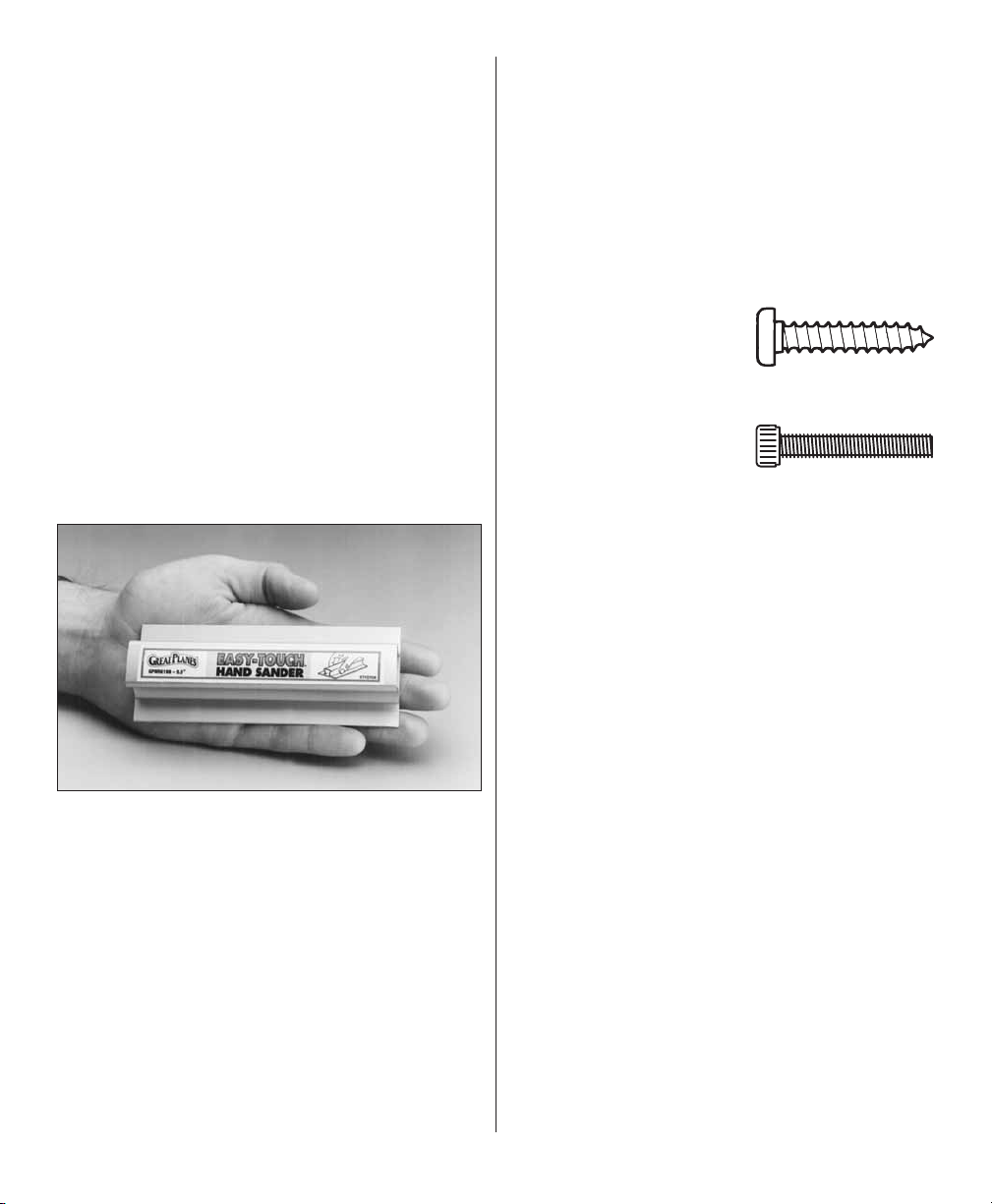
● There are two types of screws used in this kit:
Sheet metal screws are
designated by a number
and a length.
For example #6 x 3/4"
Machine screws are
designated by a number,
threads per inch and a
length.
For example 6-32 x 3/4"
● When you see the term “test fi t” in the instructions,
it means you should fi rst position the part on the
assembly without using any glue, then slightly
modify or “custom fi t” the part as necessary for
the best fi t.
*A fl at, durable, easy-to-handle sanding tool is
a necessity for building model airplanes. Great
Planes makes a complete range of Easy-Touch™
Bar Sanders and replaceable Easy-Touch
adhesive-backed sandpaper. For the Butterfl y all
that is required is the short 5-1/2" Bar Sander
(GPMR6169) and two assortment packages of
adhesive-backed sandpaper (GPMR6189).
For future reference, here’s a list of Easy-Touch
Bar Sanders and adhesive-backed sandpaper:
5-1/2" Bar Sander (GPMR6169)
11" Bar Sander (GPMR6170)
22" Bar Sander (GPMR6172)
● Whenever just “epoxy” is specifi ed you may
use either 30-minute epoxy or 6-minute epoxy.
When 30-minute epoxy is specifi ed it is highly
recommended that you use only 30-minute epoxy
because you will need either the working time
and/or the additional strength.
Common Abbreviations
Fuse = Fuselage
Stab = Horizontal Stabilizer
LE = Leading edge (front)
TE = Trailing edge (rear)
Ply = Plywood
" = Inches
5
Page 6
Types Of Wood
Balsa Basswood Plywood
Cyanoacrylate Glue
The most popular type of glue modelers use for
general construction of R/C models is Cyanoacrylate
or CA glues. Modelers build with CA because
it cures fast (immediately in some cases) and
the pieces do not have to be clamped or pinned
together as they do with traditional adhesives.
CA’s do, however have their own set of special
procedures and precautions that you should follow.
Always use CA in a well ventilated area. Open some
windows or place a fan in the room to circulate the
air. Do not lean directly over your work when you
use CA and look away while it cures or “sets off.”
CA can cure immediately upon contact with skin
so if you accidentally bond your fi ngers, do not
use vigorous motion to separate them. Use CA
Debonder (GPMR6039) or acetone (nail polish
remover) or soak your fi ngers in warm water for
a few minutes. Never point the tip of a CA bottle
toward your face and be especially careful when
you unclog a CA tip. Hobbico CA Applicator Tips
(HCAR3780) are highly recommended and will
help keep the bottle from clogging. Keep paper
towels or tissues close by to immediately absorb
excess CA dropped on your model or work area.
Read all the warning labels on your CA bottle.
other conditions that require one or the other types
of CA. For the Butterfl y all you really need is thin
and medium CA.
CA Accelerator is a chemical that you can spray
over uncured CA to make it cure immediately. A
mist spray of accelerator will do the job. Do not
inhale the vapors! Some modelers “preprime” the
parts to be glued with accelerator, join them, then
add the CA. This way the CA is guaranteed to cure
immediately. This prepriming is especially handy
when you use thin CA because it will cure before all
of the glue soaks into the wood away from the glue
joint. We do not recommend you build your entire
model with this method and use accelerator only
when necessary. Often, overspray from accelerator
used hours or even days earlier on nearby glue
joints will cause the CA you use on the next step to
cure prematurely and unexpectedly – so be careful!
Build the Tail Surfaces
Build the Fin
Place your building board on top of your fl at building
table. Position the plan sheet so the rudder and
fi n drawing is over your fl at building board. (Reroll
the plan sheet inside out to make it lie fl at or use
weights or tape to hold it down.) You may separate
the wing portion from the plan or fold the plan in
half to make it easier to work with. Cover the fi n
drawing with wax paper so the glue will not stick.
There are different viscosities of CA’s intended for
different conditions you will encounter when you
build. Thin CA is great for “tack-gluing,” for glue
joints that fi t well and for parts that are already
joined but need to be permanently bonded. Medium
CA is used for general construction where you apply
glue to one part, then join it to another part. Thick
CA is great for glue joints that don’t fi t perfectly
or parts that require a little time for positioning
before the glue cures. You will encounter many
Refer to this photo while you build the fi n.
❏ 1. Cut the fi n trailing edge from a 1/4" x 3/8"
x 36" balsa stick, then pin it over its location on
the plan. Many modelers fi nd that they can more
6
Page 7
accurately cut small balsa sticks (such as the ones
used in the tail surfaces) with a single-edge razor
blade rather than a hobby knife.
❏ 2. Cut the fi n leading edge from a 1/4" x 1/4" x 24"
balsa stick, then pin it over its location on the plan.
❏ 3. Cut the two base pieces and the tip of the
fi n from the same 1/4" x 1/4" balsa stick, then glue
them to the LE (leading edge) and TE (trailing edge)
with medium CA and pin them in position.
❏ 4. Cut the two fi n “ribs” from one of the 1/8" x
1/4" x 24" balsa sticks, then glue them in position
over their location on the plan.
❏ 5. Make the gusset for the corner of the fi n TE
and the base of the fi n from the 1/4" x 3/8" balsa
stick you used in step 1.
❏ 6. Remove the T-pins, then lift the fi n from your
building board. We will instruct you to build the
dorsal part of the fi n after you position the fi n on
the fuselage. Reinforce glue joints that don’t look
strong with medium CA.
Build the Rudder, Stabilizer
and Elevator
Use the following building sequence for the rudder,
stabilizer and elevator as a guide to cut the balsa
sticks and pin them to the plan, then glue them
together the same as you did for the fi n. Don’t
forget to cover the plan with wax paper.
Rudder Building Sequence
❏ 2. The TE, then the bottom from a 1/4" x 1/2"
x 12" balsa stick.
❏ 3. The “balance tab” part of the rudder and the
tip from the remainder of the 1/4" x 1/4" balsa stick
you used for the fi n and another 1/4" x 1/4" x 24"
balsa stick if needed.
❏ 4. The “ribs” from the remainder of the 1/8" x
1/4" stick you used for the fi n.
❏ 5. Remove the T-pins and lift the rudder from the
building board. Reinforce glue joints that don’t look
strong with medium CA.
Stabilizer Building Sequence
Refer to this photo while you build the stabilizer.
❏ 1. The TE, LEs, tips, then LE “brace” from two
1/4" x 3/8" x 36" balsa sticks. To make the brace for
the LE, fi rst cut the 1/4" x 3/8" piece to a length of
4-1/4", then mark a centerline. Use a straightedge
and a hobby knife with a #11 blade to cut the angle
on the brace that extends from the centerline to
both corners.
Refer to this photo while you build the rudder.
❏ 1. The LE from the remainder of the 1/4" x 3/8"
stick used in step 1 of the fi n.
❏ 2. 1/8" x 1/4" x 24" basswood stab spar.
❏ 3. The stab center (in front of and behind the
basswood spar) from the 1/4" x 1-1/2" x 3- 7/8"
balsa sheet.
❏ 4. The stab ribs from 1/8" x 1/4" x 24" balsa sticks.
❏ 5. Remove the T-pins and lift the stab from your
building board. Reinforce glue joints that don’t look
strong with medium CA.
7
Page 8
Elevator Building Sequence
Refer to this photo while you build the elevator.
❏ 1. The LEs as shown on the plan, cut from a 1/4"
x 3/8" x 36" balsa stick. Use a hobby knife to cut
the “notches” for the 3/16" elevator joiner dowel.
Pin the LEs to the plan.
❏ 2. The TEs and tip ends from the remaining
1/4" x 3/8" balsa sticks from previous steps. Do
not make the elevator root ends until instructed
to do so (the roots are the ends of the elevators
nearest the fuselage).
❏ 3. Test fi t the 3/16" x 3-3/4" elevator joiner
dowel in the notches in the LEs of the elevators,
then if necessary adjust the notches so the dowel
is parallel to the TE of the stab on the plan.
❏ 4. Glue the dowel in position with epoxy. Stick
T-pins into your building board in front of the dowel
to hold it against the elevators. Slightly raise the
dowel so it is centered in the LEs, then wipe away
excess epoxy before it cures.
❏ 5. After the epoxy fully cures cut, then glue the
elevator root ends to the assembly.
❏ 6. The elevator ribs from remaining 1/8" x 1/4"
balsa sticks, then the control horn base for the right
elevator from leftover 1/4" x 3/8" balsa.
A note about sanding
“built-up” tail surfaces
Be careful when you sand a balsa structure
made up of “sticks.” The part fl exes and moves
while you sand and it can be diffi cult to keep your
sanding block fl at so you do not snag any of the
small ribs or over-sand one area and thin it more
than another area. Due to the design and slow
fl ying speed of the Butterfl y, a perfectly smooth
fi nish is not necessary. For this model, the
purpose of sanding is just to remove any glue
bumps or uneven edges. Stop sanding when
you have reduced most of the high spots. Use a
large sanding block or a fl at bar sander and do
not apply much pressure while you sand. Enjoy
– it’s not a racing plane – it’s a fl oater.
❏ 7. Remove the elevator from the plan, then add
CA to glue joints that don’t look strong.
Finish The Tail Surfaces
❏ 1. See the note below, then use your bar sander
or a sanding block and 220-grit sandpaper to even
the edges and blend the ribs, LEs and TEs of all
the tail surfaces so they are fl at and smooth.
❏ 2. Use a ballpoint pen to mark the location of
the hinges on the control surfaces as shown in
the photo.
Note: The plan shows two hinges in each elevator
but use three as indicated in the photo.
8
Page 9
❏ 3. Lay the stabilizer on your building table. Use
thin card stock or business cards to raise the stab
so you can mark the hinge slots in the center of
the TE at the hinge locations. Mark the hinge slots
in the TE of the fi n the same way.
❏ 6. Test join (remember, this means no glue)
the elevator to the stab and the rudder to the fi n
with the hinges. Adjust the width of the hinge
slots if necessary.
❏ 4. Use the same procedure to mark the centerline
the entire length of the LE of the rudder and the
elevator.
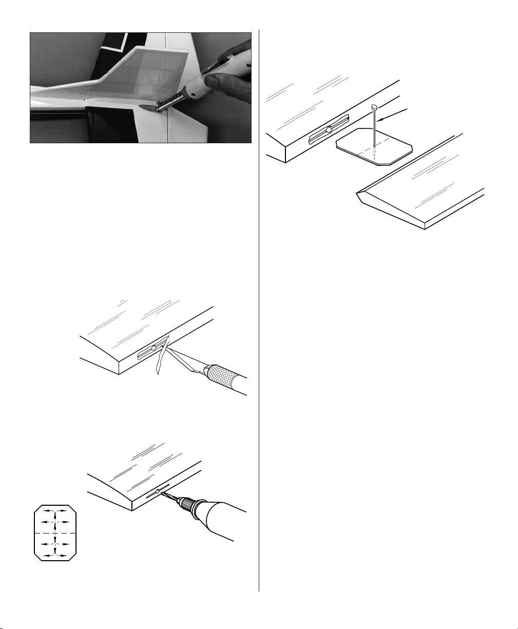
Cut the Hinge Slot with a
Hobby Knife and a No. 11 Blade
❏ 5. Use a hobby knife with a #11 blade to make
the hinge slots. The fi rst cut should be a shallow
slit to establish the hinge slot location. After the fi rst
cut, make several more cuts going slightly deeper
each time. Move the knife from side to side and
widen the slot as you cut.
1"
1"
❏ 7. Separate the elevator from the stab and the
rudder from the fi n. Use the “pen-and-card stock”
technique to mark a guideline 3/32” to 1/8" from
the LE on both sides of the elevator and rudder.
The guidelines indicate where to round the LE for
control movement.
❏ 8. Use the guidelines and a sanding block or
razor plane to round the leading edges of the rudder
and elevator equally.
❏ 9. Mark a centerline on the trailing edge of the
rudder and elevator with a ballpoint pen. Use your
bar sander or sanding block and 150-grit sandpaper
to taper the rudder and elevator as shown on the
cross-section of the plan or simply round the trailing
edges the same as the leading edges.
Build the Wing
Snip the Corners
3/4"
Cut eight hinges from the hinge material supplied
as shown in the sketch. Snip the corners off so
they go into the slots easier.
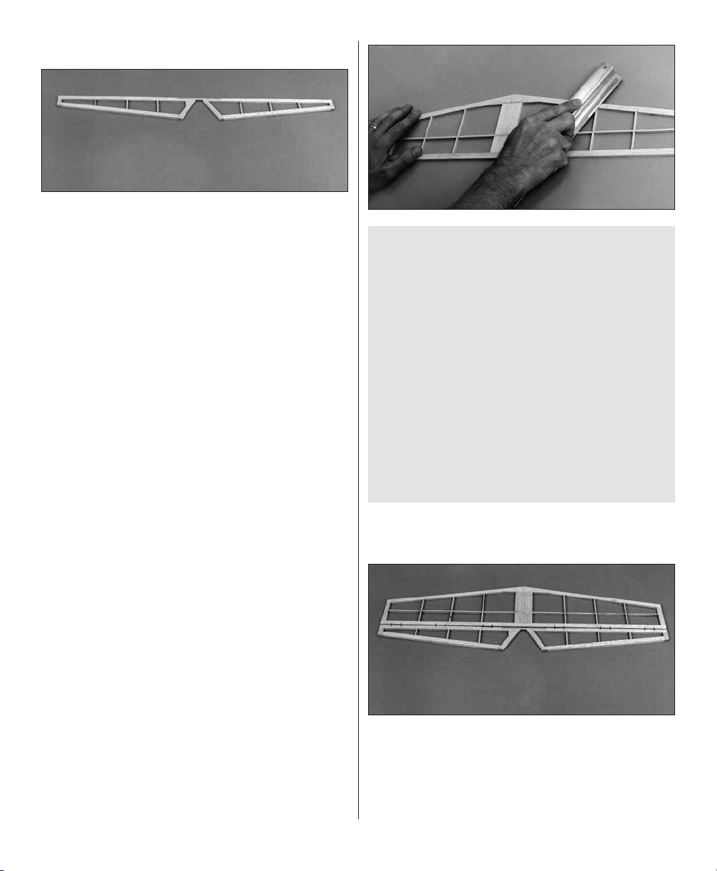
Build the Inner Wing Panels
Build the right wing half fi rst so your progress
matches the photos in the manual. Lay the right
wing plan over your building board, then cover the
plan with wax paper.
9
Page 10
❏ 1. Before you remove the balsa ribs from their
die sheets, use the photos to identify the ribs and
mark them with a ballpoint pen as shown. If you
plan to cover the wing with transparent MonoKote
fi lm, mark the ribs neatly all in the same location
or mark them in an inconspicuous location so the
marks will not be seen through the covering.
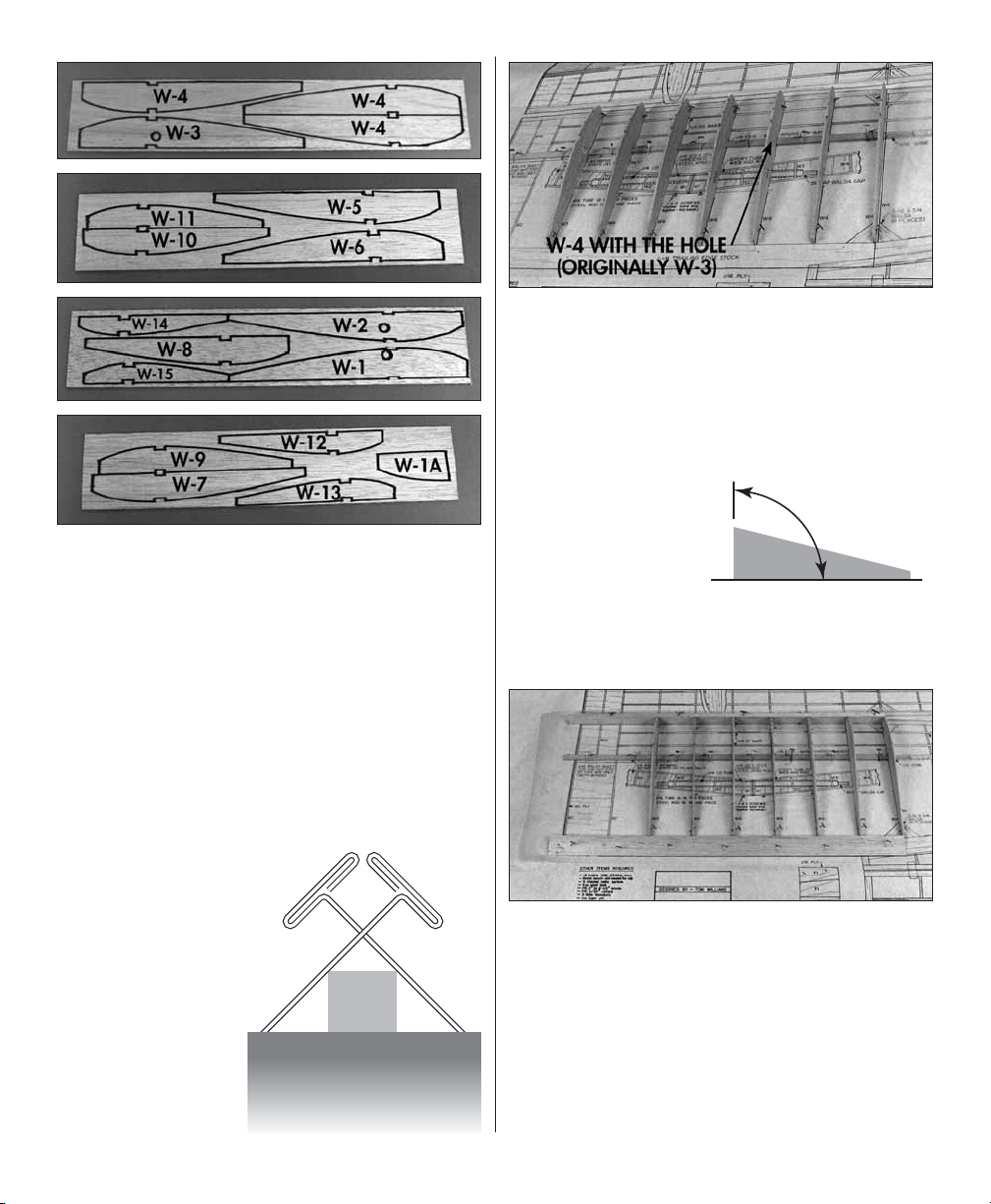
❏ 2. Remove all the ribs from their die sheets, then
use a bar sander and 220-grit sandpaper to remove
any slivers or die-cutting irregularities. Save the
leftover 1/16" plywood from the W-1s to be used
later during fi nal landing gear installation.
❏ ❏ 3. Pin a 1/8" x
3/8" x 24" basswood
T-Pin
bottom inner spar
over its location
on the plan so the
tip “ends” at the
centerline between
the laminated W-4s
Spar
as shown on the plan.
Do not insert T-pins
Work Surface
through the spar
but install them in a
criss-cross pattern.
❏ ❏ 4. Position rib W-3 on the bottom spar and pin
it to the building board over its location on the plan.
Position the six W-4s of the inner wing panel on
the spar and pin them to the building board as well.
Note: Substitute the third W-4 rib in from the tip
with a W-3.
❏ ❏ 5. Position a
3/8" x 1-1/4" x 21"
90º
tapered balsa inner
TE over its location
on the plan so the
tip aligns with the
Bottom
centerline at the
laminated W-4s on the plan. Securely pin the TE to
the building board so it tightly contacts the wing ribs.
❏ ❏ 6. Position a 3/8" x 3/4" x 21" balsa inner LE
over its location on the plan so the tip aligns with
the centerline at the laminated W-4s on the plan.
Securely pin the LE to the building board so it tightly
contacts the wing ribs.
10
Page 11
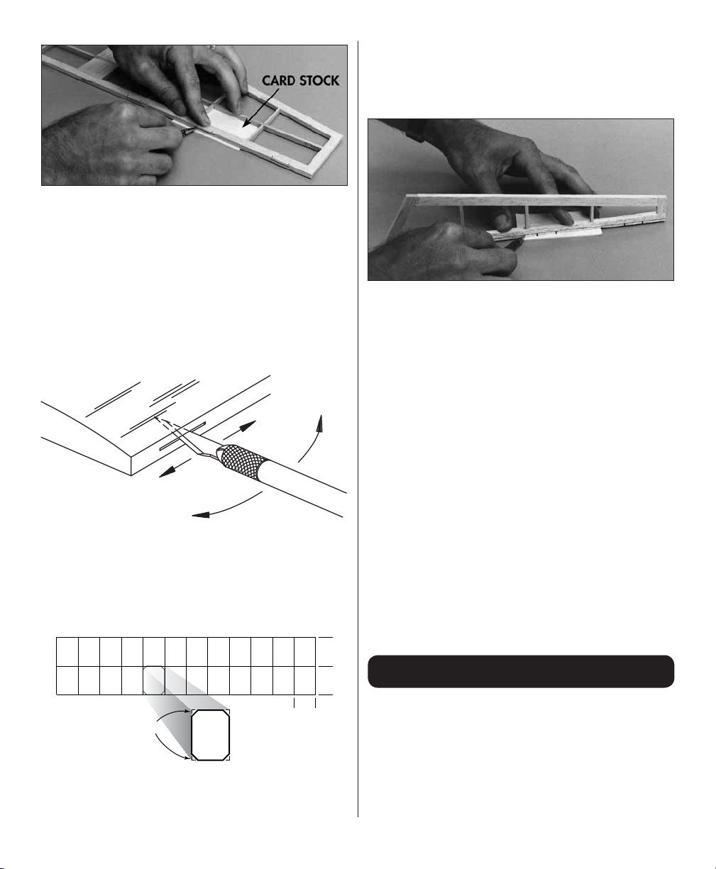
❏ ❏ 7. Remove the T-pins in rib W-3. Use a 90-
degree triangle to hold W-3 perpendicular to the
building board, then glue it to the spar, LE and TE
with medium or thin CA. Glue the W-4s to the spar,
LE and TE the same way.
❏ ❏ 10. Use medium or thin CA to glue the sheets
in position so the outer edges align with the outer
edge of rib W-2. The sheeting will be sanded fl ush
with the balsa W-1 after the wing is removed from
the plan.
❏ ❏ 8. Use the die-cut 1/8" plywood wing center
gauge to accurately mark where the balsa W-1
contacts the LE so you know where to position W-1
after the bottom sheeting is glued in place. Mark
the TE the same way.
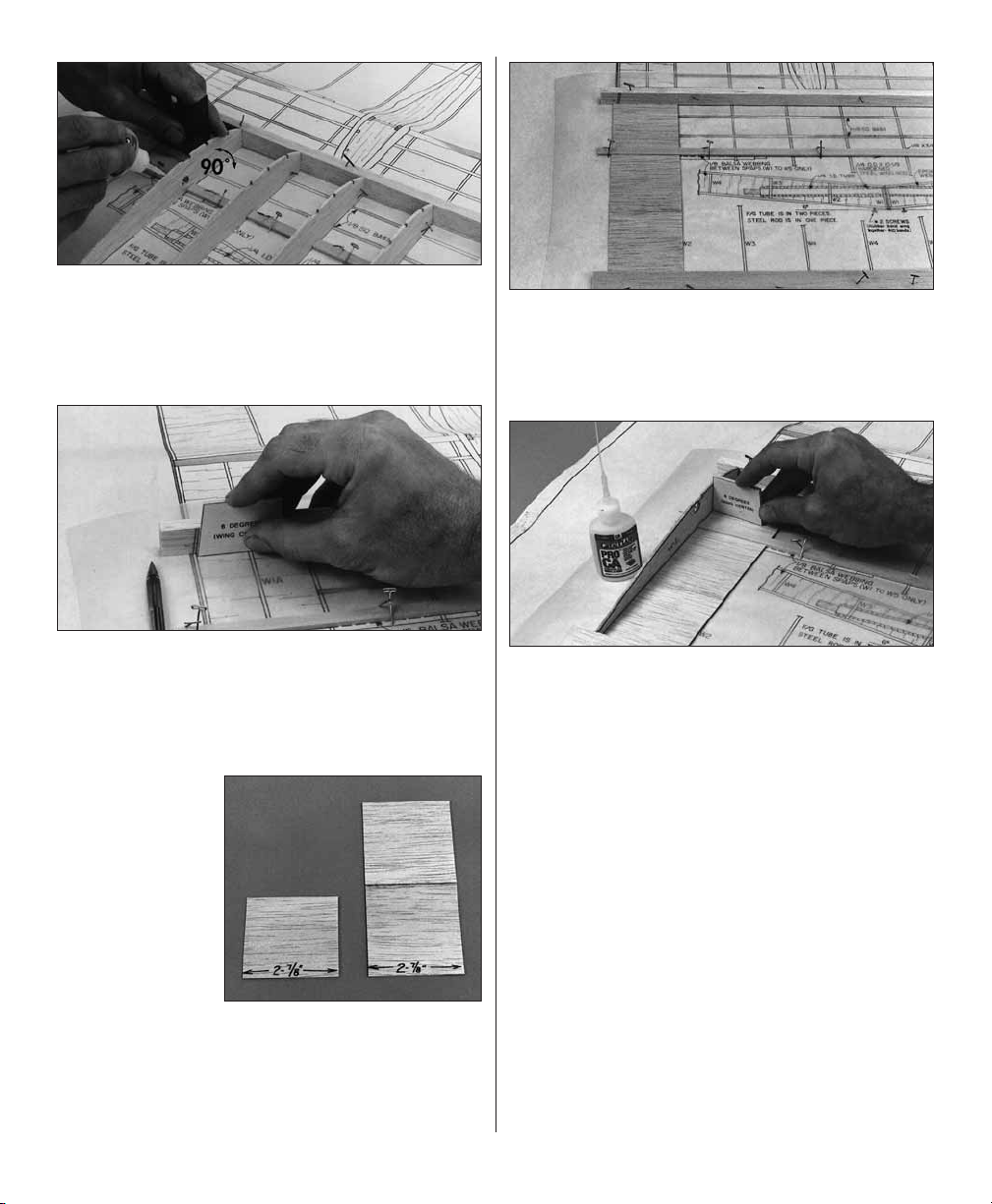
❏ ❏ 9. Cut three
2-7/8" wide strips
from the 1/16" x 3"
x 36" balsa sheet.
Glue two of the
strips together
to make the aft
bottom sheeting
behind the bottom
spar. The other
strip is to be used
for the forwar d bottom sheeting ahead of the spar.
Use a straightedge and a sharp #11 blade to trim
the sheets so they fi t between the LE and bottom
spar and the TE and bottom spar, but leave the
sheets 2-7/8" wide.
❏ ❏ 11. Align W-1 with the marks on the LE and
TE, then glue it in position using the wing center
gauge to set the correct angle.
❏ ❏ 12. Glue W-2 in position with thin or medium
CA. While gluing, hold W-2 perpendicular to your
building board as you did with the W-4s.
❏ ❏ 13. Trim, test fi t, then glue the 1/8" balsa
vertical grain shear webs between only the W-4
ribs (that’s fi ve shear webs). Note that the shear
webs between the W-4s are centered on the bottom
spar. You will have to temporarily remove the T-pins
that interfere with the shear webs, then replace the
T-pins through the shear web after you glue each
web into position. See the following photo.
❏ ❏ 14. Trim and test fi t, but do not glue the
remaining shear webs. Use the wing center gauge
to cut the angle for the shear web that fi ts between
W-1 and W-2.
11
Page 12
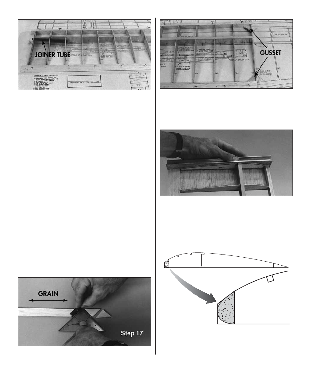
❏ ❏ 15. Slide the composite wing joiner tube
into the holes of W-1, W-2 and W-3. The holes in
the ribs are slightly oversize so you can accurately
position the tube when you permanently glue it
into the wing. Position the joiner tube so it rests
against the forward edge of the holes in the ribs,
then position the shear webs so they contact the
tube yet remain vertical. Glue the shear webs to
the wing (not the joiner tube) in this position.
❏ ❏ 16. Remove the joiner tube, then test fi t the
1/8" x 3/8" x 21" basswood inner upper spar in
the notches of the ribs. Make sure none of the
crossed T-pins interfere with the top spar and you
will be able to remove them after you permanently
glue the spar into position. If necessary, trim the
shear webs that do not allow the spar to rest fully
into the notches of the ribs. Use medium or thick
CA to glue the upper spar to the assembly so the
end is even with the outer rib W-4.
❏ ❏ 17. Make two gussets from the 3/16" x 3/4" x
12" balsa sheet, then glue them in position. If you
have one, use a small building triangle to accurately
cut the gussets. Note the grain direction as shown
in the photo.
❏ ❏ 18. Remove the T-pins and lift the wing panel
from your building board. Trim the ends of the spars,
LE and TE, then use your bar sander and 150-grit
sandpaper to make the spars, LE, TE and bottom
sheeting fi t perfectly fl ush with W-1.
❏ ❏ 19. Glue W-1A into position with medium CA.
❏ ❏ 20. See the Tip that follows, then use a razor
plane, a hobby knife with a carving blade or a #11
blade to roughly carve the leading edge according
to the sketch.
12
Page 13

Note: Leave the leading edge at least 1/16" high
"
in front of ribs W-1, 2 and 3 to accommodate the
top sheeting. You will fi nal sand the LE after you
join the inner panels to the outer panels and glue
the top sheeting in position.
TIP: How To Use A Razor Plane
We highly recommend a razor plane to shape
the LEs because it is the safest, fastest and
most accurate method to remove large quantities
of balsa.
A. Adjust your razor plane so it removes about
1/64" or less balsa at a time.
B. Position the LE of the wing panel at the edge
of your work bench so it is supported and the
bench does not interfere with the razor plane.
Area to Trim Off
3/4
❏ ❏ 1. Trim the end of a 3/8" x 1-1/4" x 30" tapered
balsa outer trailing edge so it matches the angle at
W-4 shown on the plan. Mark the tip end of the TE
3/4" away from the aft edge. Use a straightedge and
a ballpoint pen to mark a line on the TE connecting
the mark you made at the tip with the forward edge
of the other end (the root) of the TE.
❏ ❏ 2. Use the line you marked (or a straightedge)
as a guide to trim the TE with a sharp #11 hobby
knife as shown on the wing plan.
❏ ❏ 3. Cover the outer panel of the right wing plan
with wax paper, then use the “crossed T-pin” method
to pin the 1/8" x 3/8" x 30" basswood bottom outer
main spar in position so the root end aligns with
the plan at W-4.
❏ ❏ 4. Position the odd numbered ribs and
W-4 on the bottom spar, then pin them to your
building board.
C. Hold the razor plane at an angle to the grain
direction as shown in the photo.
D. Work slowly and inspect your work frequently.
Before you know it you will shave the LE down
quite far.
❏ 21. Arrange the plan so the left inner wing panel
is over your building board, then cover it with wax
paper. Return to step 3 and build the left inner wing
panel the same way as the right. Don’t forget to
switch to the left wing panel plan so you do
not build two right panels.
Build the Outer Wing Panels
Start with the right outer wing panel so your
progress matches the photos in the manual.
❏ ❏ 5. Pin the outer TE and the 3/8" x 3/4" x 30"
balsa outer LE to the building board so they tightly
contact the ribs and the ends align where indicated
on the plan at W-4.
13
Page 14
❏ ❏ 6. Remove the T-pins from rib W-4. Use the
wing tip panel gauge to set W-4 at the correct
angle and glue it to the TE, bottom spar and LE.
❏ ❏ 7. One rib at a time, remove the T-pins and use
a building triangle to hold the rib vertical, then use
medium or thin CA to glue the ribs you installed to
the bottom spar, LE and TE.
❏ ❏ 8. Install, then glue the remaining ribs to the
assembly using a building triangle to make sure
they are vertical.
❏ ❏ 9. Cut, then install the gussets at W-4 from
the 3/16" x 3/4" balsa stick. Due to the taper of
the LE and TE these gussets are not exactly a
90-degree angle.
❏ ❏ 10. Add the 1/8" balsa cross-grain shear web
between W-4 and W-5. Use the die-cut 1/8 plywood
wing tip panel gauge to cut the end of the web
that contacts W-4.
❏ ❏ 11. Test fi t, then use medium or thick CA to
glue the 1/8" x 3/8" x 30" basswood top outer spar
to the ribs and shear web. Don’t forget to make
sure the crossed T-pins are not in the way and you
can remove them after you permanently glue the
spar into position.
❏ ❏ 13. Remove the T-pins, then lift the panel
from the plan. Use a razor saw to cut the ends of
the spars, LE and TE so they extend past W-15 by
approximately 1/32" to 1/16". Use your bar sander
to sand the ends fl ush with W-15 and W-4.
❏ ❏ 14. Use a razor plane, a hobby carving blade
or a #11 blade to roughly carve the leading edge
the same way as you carved the inner wing panels.
❏ ❏ 12. Test fi t, then use medium CA to glue both
1/8" x 1/8" x 30" balsa outer turbulator spars in
the notches of the ribs so the ends extend past
W-4 by approximately 1/16" (you can sand them
fl ush later).
❏ ❏ 15. Glue the 3/4" x 6-1/4" triangle balsa wing
tip to W-15. The aft edge of the wing tip should
align with the aft edge of the TE. It may appear
that the triangle wing tip is too short because it
does not align with the LE, but as indicated on the
plan you will shape the LE to align with the wing tip.
14
Page 15

❏ ❏ 16. Roughly carve the wing tip with a razor
plane or a hobby knife. Final shape the tip and blend
it to W-15 with a bar sander and 150-grit sandpaper.
❏ ❏ 17. Carefully remove any glue blobs and blend
all the ribs to the spars, TE and LE with a bar sander
and 220-grit sandpaper.
❏ 3. Without any glue, temporarily join both inner
wing panels with the joiner tubes and the joiner
rod. Hold the wing halves together and inspect
the fi t between the W-1 ribs of the joining panels.
If necessary, separate the panels and use your bar
sander to adjust to the ends of the spars, LEs or
TEs so the W-1s fi t together well.
❏ 18. Arrange the plan so the left outer wing panel
is on your building board, then cover it with wax
paper. Return to step 1 and build the left wing panel
the same way you built the right. Don’t forget to
switch to the left wing panel plan so you do
not build two right panels.
Join the Inner Panels
Do not permanently join the inner wing panels, but
permanently install the joiner tubes so you can
temporarily join the panels for a days fl ying session.
Take the panels apart when it is time to go home.
❏ 1. Thoroughly roughen the outside of the wing
joiner tubes with 150-grit sandpaper so the glue will
stick. Use a metal fi le or a powered hand tool with
a cut-off wheel to remove the burrs and chamfer
the ends of the 1/4" x 10-1/2" steel wing joiner rod.
Remove any dirt or manufacturing oil from the rod
with a cloth dampened with alcohol or other solvent.
❏ 2. Plug one end of both wing joiner tubes with a
piece of 3/32" or 1/8" leftover balsa, then carefully
glue the plug in position with a few drops of thin
CA. Do not allow CA to fl ow into the tube because
it may interfere with the joiner rod.
❏ 4. With the joiner tubes and the joiner rod
in position, temporarily clamp the wing halves
together, then place a weight on one of the wing
panels to hold it down. Measure the height of the
outer W-4 from the building table. It should be
approximately 4-1/2".
❏ 5. Remove your clamps, then position 1/8"
leftover balsa “spacers” between the W-1s and
clamp them together. The spacers will allow both
joiner tubes to protrude 1/16" from the inner panels.
❏ 6. Use a stack of books, blocks of balsa or similar
to support the raised wing panel at W-4. Align the
joiner tubes so the ends meet in the center of
the wing and clamp the tubes to the shear webs.
“Spot-glue” the ends of the joiner tubes in each
wing panel with medium CA or epoxy.
15
Page 16
❏ 7. Carefully lift the wing from your building board
so you do not break the spot-glued joints, then place
it on the leading edges. Mix a batch of 30-minute
epoxy, then thoroughly glue the joiner tubes to the
shear webs, spars and ribs. Do not disturb the
wing until the epoxy cures.
❏ 8. Remove the clamps and separate the wing
panels. Make the top center section sheeting for
both wing panels from the remainder of the 1/16"
x 3" balsa sheet. Test fi t the sheets and confi rm
that the front and rear edges are fl ush with the TE,
upper spar and LE. If needed, trim the tops of the
ribs. Bevel the front edge of the front sheet so it
matches the LE, then glue the sheets in position.
❏ 9. Use a hobby knife and your bar sander with
150-grit sandpaper to trim the edge of the sheet
so it is even with W-1. Do not trim the ends of the
joiner tubes so they are fl ush with W-1.
❏ 10. Cut both of the TEs as shown on the plan.
Cut the 1/8" x 4" hardwood dowel into two pieces,
then test fi t and glue the dowels to the TEs of both
wing panels with medium CA. Use your bar sander
to true the end of the dowels so they are fl ush with
the ends of the wing.
❏ 11. Test fi t the die-cut 1/16" plywood W-1 root
ribs on the ends of the wing panels and the joiner
tubes. Then, glue them in position with medium
or thick CA. If you’ve just removed the W-1’s from
their die sheet, remember to save the leftover 1/16"
plywood to be used later during fi nal landing gear
installation.
❏ ❏ 12. Test fi t the 1/8" x 1/8" x 18" basswood
turbulator spars in the notches of the right wing
panel. The ends of the spars contact the center
sheeting and the tops of the spars are even with
the sheeting as shown in the following photo. If
necessary, adjust the notches so the spars fi t
fl ush with the tops of the ribs, then glue the spars
in position with thin or medium CA.
16
Page 17
❏ ❏ 13. Glue a piece of 1/8" leftover balsa to rib
W-2 to support the turbulator spars. Trim the ends
of the spars so they are even with the end of the
panel at rib W-4.
1/16" Holes
❏ 14. Glue the turbulator spars in the left wing
panel the same way.
❏ 15. Use a bar sander and 220-grit sandpaper on
both inner wing panels to carefully remove any glue
blobs and blend all the ribs to the spars, TE and LE.
Join the Outer & Inner Wing Panels
❏ 1. Remove the burrs and chamfer the ends of
the four 1/16" x 5" wing panel joiner wires with
a metal fi le or a powered hand tool and a cut-off
wheel. Remove any oil from the wires left from the
manufacturing process with a cloth dampened with
alcohol or other solvent. Thoroughly roughen the
wires with 150-girt sandpaper so the glue will stick.
❏ ❏ 2. Test fi t the right inner wing panel to the
right outer wing panel. If necessary, use your bar
sander to adjust the ends of the spars, LEs or TEs
for a good fi t.
❏ ❏ 4. Use a hobby knife or a 1/16" drill to make
two holes in both W-4 ribs to accept the wire wing
panel joiners. Bend, then test fi t the joiner wires.
Adjust the bends so the wires accurately match
the “bend” in the wing and fully contact the spars.
❏ ❏ 5. Apply a thin fi lm of epoxy to the W-4 ribs,
then join the two panels with the joiner wires.
Support the tip the same way you did when you
joined the inner panels. Place a sheet of wax paper
under the wing to protect your building board from
excess epoxy, then clamp the W-4 ribs together.
Wipe away excess epoxy before it cures. Do not
apply epoxy to the joiner wires until instructed
to do so.
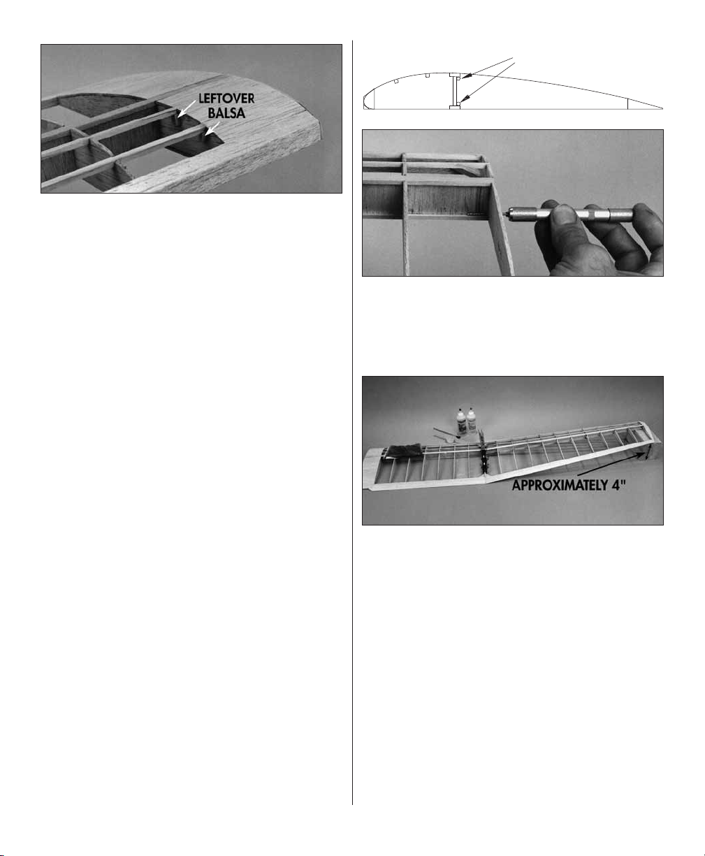
❏ ❏ 3. With the mating W-4 ribs contacting each
other and the inner wing panel laying fl at on your
building table, rib W-15 of the outer panel should be
approximately 4" off the table. If necessary, adjust
the ends of the spars at the W-4s to achieve the
approximate 4" measurement.
17
Page 18
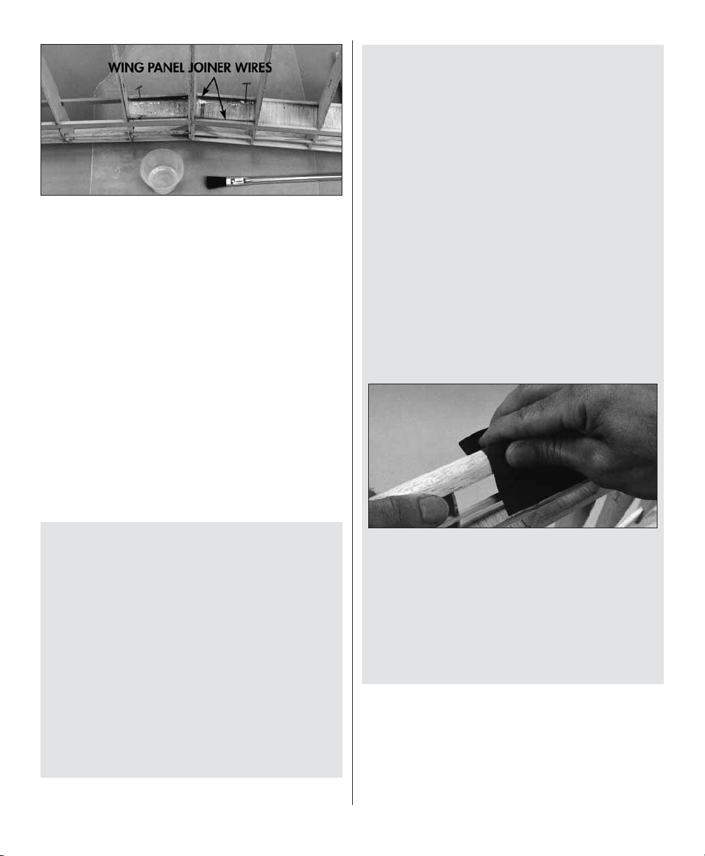
❏ ❏ 6. After the epoxy has fully cured, carefully
prop the wing up on its leading edge, then apply
30-minute epoxy to the wing joiner wires to securely
glue them to the shear webs and spars. Use T-pins if
necessary to hold the joiner wires against the spars.
Do not disturb the wing until the epoxy cures.
❏ 7. Return to step 2 and join the panels of the
other wing half the same way.
Finish the Wing
❏ 1. Drill a 1/16" hole in the bottom spar of both
wing halves where shown on the plan for the #2 x
3/8" screws to secure the wing halves with rubber
bands. We will instruct you to install the screws
after you cover the wings.
Here are some tips that can make shaping your
LEs a little easier and faster:
A. While you shape the LEs, frequently reference
the cross-section on the plan and the drawings
of the LE gauges on the plan. If you are a
perfectionist, cut the gauges from the plan, then
use rubber cement or spray adhesive to glue
them to leftover 1/8" plywood or thin cardboard
(such as a cereal box). Cut the gauges from the
wood or cardboard you glued them to, then test
fi t the gauges to the appropriate sections of the
wing to arrive at the correct shape.
B. We highly recommend a razor plane to shape
the LEs until they are nearly the shape shown on
the plan – leave enough material to fi nal shape
by sanding.
C. Shape the LEs of the inner panels fi rst since
they have a constant shape from W-1 to W-4.
❏ 2. See the Tip that follows, then shape the LEs
of both wing panels.
Tip: How To Final Shape The LEs
The Butterfly is a motor glider not a high
performance aerobatic model – it’s named the
“Butterfl y” after all! It is not critical that you shape
the leading edges with the greatest precision. You
probably would not notice any difference in the
fl ight performance of a Butterfl y with a leading
edge accurately fi nished by an expert builder and
a Butterfl y with a leading edge roughly carved to
shape with a hobby knife. This isn’t to say that
you should not always strive for building accuracy
and a good fi nish, but don’t worry if your LEs
don’t look perfect. Building a straight fuselage
and fl at, warp-free wings are where you should
concentrate most your building efforts.
D. After you roughly shape the LE’s by carving
(or using the razor plane), fi nal shape the LE’s
with a bar sander and 220-grit sandpaper. Wrap
a piece of 220-grit sandpaper around the LE and
fi nal sand by hand.
E. Once you shape the inner LE’s, use the gauges
to fi nal shape the outer LE’s and blend the two
together where they meet.
❏ 3. Inspect all glue joints of both wing panels. Add
CA to all glue joints that don’t look strong.
❏ 4. Final sand the wings with your bar sander
and 320-grit sandpaper and blend all the ribs with
TE, LE and spars.
18
Page 19

Build the Fuselage
Prepare the Fuse Sides
All the parts used during fuselage construction are
die-cut 1/8" plywood unless otherwise specifi ed.
❏ 1. Carefully remove the forward and aft fusela ge
sides from their die sheets, then remove slivers or
die-cutting irregularities with a bar sander.
❏ 2. Lay the forward fuselage sides on your work
bench opposite each other in a “mirror image.”
Mark the inside of the fuselage sides as the “right
inside” and the “left inside” with a ballpoint pen.
covered with wax paper to make sure the pieces
align. Use a bar sander and 150-grit sandpaper to
sand the two sides so they are fl at and even.
❏ 5. Glue a servo rail support to the inside of both
fuselage sides at the location shown in the photo.
❏ 3. Remove the portion of only the right fuselage
side indicated by the perforated line with a hobby
knife and a straightedge.
❏ 4. Glue the aft fuselage sides to the forward
fuselage sides with medium CA. Work over the plan
❏ 6. Place one of the fuselage sides on a piece of
scrap wood, then drill a 3/16" hole at both punch
marks for the wing dowels. Press down on the
fuselage side to keep the drill from splitting the
wood as it goes through. Repeat for the other
fuselage side.
❏ 7. While you have your drill and bits out, drill an
11/64" hole at the forward landing gear wire punch
mark in the right fuse side and the aft punch mark
in the left fuselage side. If you do not have an 11/64"
drill, you may use a 5/32" drill but you will have to
enlarge the hole slightly with a hobby knife.
❏ 8. Use thin CA to glue the 1/4" x 36" balsa triangle
fuselage reinforcement stringers to the top and
bottom of the inside of both fuselage sides. Be
certain you glue the stringers to the inside
of the fuselage sides. The front of the stringers
should be 1/8" aft of the front edge of the fuselage
sides (for F-5). Make the “splice” in the stringers
as shown on the plan at the rear of the fuselage.
19
Page 20
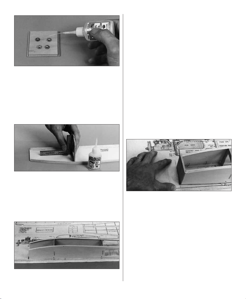
❏ 9. Use the above die drawing of the fuselage parts
to mark each part with a ballpoint pen exactly as
they are shown. This will insure proper orientation
of the formers during construction.
❏ 10. Use medium CA to glue the notched aft
fuse side joiners (F-1) to both fuselage sides so
the front edge of the notches in the joiners are 1/4"
ahead of the front edge of the notches in the fuse
sides as shown in the photo.
❏ 12. Glue F-5 to F-4 with epoxy so the edges of
F-5 align with the lines on the back of F-4 and the
top edges of F-4 and F-5 are even. From now on
this assembly will be referred to as the “fi rewall.”
Make certain that the “F-4” and “F-5” designations
you marked are in the same orientation. If the parts
are slightly warped, clamp them to a fl at table or
board with wax paper between the board and the
parts. Wipe away excess epoxy before it cures.
❏ 13. Center the engine mount (not included) on
the fi rewall so the “rails” align with the horizontal
line. Use a piece of wire sharpened at one end to
mark the location of the engine mount holes on the
fi rewall. Remove the mount and drill 1/8" holes at
the marks to fasten mount with 4-40 x 1/2" machine
screws and 4-40 blind nuts (not included). We used
a Hayes 061 KM-15 engine mount (HAYG1061)
on our prototype.
❏ 11. Use a ballpoint pen and a straightedge to
draw a line connecting the punch marks on the
front of F-4 to indicate the position of your engine
mount. Draw two vertical lines (with the grain of
the wood) on the back of F-4 1/8" from each side
to indicate the position of F-5.
20
Page 21
❏ 14. Insert 4-40 blind nuts into the holes from the
back of the fi rewall, then lightly tap them all the way
in with a hammer. Apply medium CA around the
edges of the blind nuts to permanently secure them.
❏ 15. Drill a 3/16" hole through the punch mark
in the right side of F-6 for the throttle pushrod
guide tube.
Join the Fuselage Sides
down over the top view of the fuselage plan. Make
sure the fuselage sides fully contact your fl at
building table and the formers and sides align
with the plan. Adjust the notches in the left fuse
side if necessary, then use medium CA to glue the
left side to the formers.
❏ 4. Beginning at former F-6, pin the fuselage in
position over the top view of the plan by inserting
T-pins through the triangle fuselage reinforcement
stringers into your building board. Accurately align
the fuselage with the plan as you proceed toward
the rear. Insert all the T-pins so they are all at
the same angle, slanting forward for example, so
you will be able to remove the fuselage from your
building board after you glue the sheeting in position.
Do not insert any T-pins in front of F-6.
❏ 5. Place a piece of wax paper under the front
of the fuselage at the fi rewall. Glue the fi rewall to
the fuse sides with 30-minute epoxy. Immediately
proceed to the next step.
❏ 1. Fit F-6 into the forward notch of the right
fuselage side. Use a small square or a 90-degree
triangle to hold F-6 perpendicular and use
medium CA to securely glue it in position. The
“F-6” designation must face forward.
❏ 2. Glue F-7 to the right fuse side the same way
as F-6.
❏ 3. Test fi t the left fuselage side to the assembly.
Position the temporarily joined fuse sides upside-
❏ 6. Before the epoxy cures, pin the front of the
fuselage to the plan the same way you did the rear
of the fuselage. The fi rewall should align with the
dashed line which represents the position of the
fi rewall on the plan when the fuselage is upside-
down. Use masking tape to hold the fuse sides
together until the epoxy cures.
❏ 7. Use medium or thick CA to glue a piece of
triangle stock to both corners where the fi rewall
meets the fuselage sides.
21
Page 22

Sheet the Fuse Bottom
❏ 1. Mark the location of the landing gear rails on
the bottom edges of the fuse sides and the triangle
fuse side stringers as shown in the photo. Remove
the portion of triangle stringers on both fuselage
sides between the lines you marked.
❏ 6. Remove as many T-pins as possible, then
carefully lift the fuselage off your building board
and remove the remaining T-pins.
❏ 7. Sand the ply and balsa fuselage bottom even
with the fuse sides.
❏ 8. Use a metal fi le or a powered hand tool with
a cut-off wheel to remove any burrs and chamfer
the ends of both 5/32" landing gear wires.
❏ 9. Fit one of the landing gear wires through the
hole in the right fuselage side and hold it in position
as shown on the plan. Position the landing gear
wire as accurately as you can so it has the same
amount of forward “rake” as shown on the plan.
Place the
right fuselage side next to the wire as shown on
the plan. Use thin CA to glue the aft landing gear
bearing to the fuselage side.
aft landing gear bearing
inside the
❏ 2. Position the landing gear rails between the
fuselage sides and align them with the landing gear
holes as shown on the plan. Glue the landing gear
rails in position with medium CA.
❏ 3. Sand the bottom of the fuselage with your
bar sander and 150-grit sandpaper so the formers,
triangle side stringers and the landing gear rails
are even.
❏ 4. Bevel the one end of the 1/16" x 3" x 12"
plywood forwar d fuselage bottom so it matches
the right thrust angle of the fi rewall, then glue it to
the bottom of the fuselage with medium or thick CA.
❏ 5. Cut the cross-grain bottom fuselage sheeting
from the 1/16" x 2" x 36" balsa sheet, then glue the
individual planks in position with medium CA. Use
your builders triangle to keep the fuselage sides
perpendicular as you proceed.
❏ 10. Position the f orwar d landing gear bearing
on the right fuselage side next to the landing gear
wire and glue it in position with thin CA.
❏ 11. Insert the other landing gear wire in the
fuselage and position it so it matches the angle
of the left wire. Glue the forward and aft landing
gear bearings to the left fuselage side the same
way you did for the right side.
❏ 12. Remove the landing gear wires. You will
permanently install the landing gear after you cover
the model.
Finish the Fuselage
❏ 1. Use the remaining balsa triangle stock to
reinforce formers F-6 and F-7 where shown on
the plan.
22
Page 23

❏ 2. Cut two 36" outer pushrod guide tubes to a
length of 24". Use 150-grit sandpaper to carefully
(so you do not snap them in two) roughen the
outside of the tubes so glue will stick to them. Save
the remaining 12" from one of the tubes for the
throttle pushrod guide tube.
❏ 3. Use a small, round wood fi le or a hobby knife
to bevel the aft edge of the slot in both fuselage
sides for the pushrod guide tubes.
Forward
❏ 5. Position the guide tubes so approximately 1/2"
protrudes from the slots at the rear of the fuselage.
Use medium CA to glue only the aft support in
position but do not glue the tubes to the support
and do not glue the front support in position until
instructed to do so.
❏ 6. Glue the pushrod guide tubes in the slots in the
rear of the fuselage with thin CA, then fi ll the slots
with HobbyLite fi ller or glue the tubes in the slots
with epoxy and microballoons. If you’ve never heard
of microballoons, it’s a powder made of microscopic
glass “balloons” that you mix with epoxy to use as
a fi ller or adhesive. The microballoons and epoxy
mixture is harder to sand than regular fi ller so it
is used only where structural strength is required.
Aft
❏ 4. Make a forwar d and aft pushr od guide tube
support as shown in the sketch from leftover 1/4"
x 3/8" balsa. Position the aft support as shown in
the photo and position the forward support in front
of F-7. Insert the pushrod guide tubes.
❏ 7. Sand the fi ller and pushrod tubes with your
bar sander and 150-grit sandpaper so they are
fl ush with the fuselage sides.
❏ 8. Glue the pushrod tubes to only the aft support.
❏ 9. Use your bar sander to sand the tops of the
fuse sides so the formers, the triangle side stringers
and the fuse sides are all even.
❏ 10. Position the stab on the fuselage so the
trailing edge is 1" aft of the end of the fuse (as
shown on the plan). Use a ballpoint pen to mark
the location of the stab leading edge on the top of
the fuse sides and triangle stringers.
23
Page 24

❏ 11. Cut the cross-grain aft top fuselage
sheeting from the 1/16" x 2" x 24" balsa sheet
and the remainder of the 1/16" balsa sheet you
used for the bottom of the fuse. Position and glue
(with medium CA) the individual planks between
F-7 and the marks you just made.
❏ 12. Trim, then sand the sides of the top sheeting
so it is even with the fuse sides. Sand the top
sheeting so it is fl at, even and smooth.
❏ 13. Make the cabin sides from the 1/4" x 1/2"
balsa sticks, then glue them to the top of the fuse
sides in the location shown on the plan.
❏ 14. Mount the engine mount to the fi rewall
with 4-40 x 1/2" machine screws and blind nuts
(not included).
❏ 16. See the information about fuel tanks that
follows, then test fi t a 4 oz. fuel tank in the fuselage.
You may support the tank with layers of foam (“R/C
foam” used to protect receivers and batteries and
cushion fuel tanks) or build fuel tank supports
from leftover 1/8" plywood. Place one layer of 1/4"
foam between the tank and the tank fl oor.
A Crash Course In Fuel Tanks
A. In order f or an engine to draw fuel from the
tank, three things are important:
1. The pick-up line inside the tank must be cut
to a length so it is as long as possible, yet does
not allow the “clunk” (the weight at the end of the
line) to contact the rear of the tank. If the clunk is
able to touch the rear of the tank, it may become
stuck in a position that is above the fuel level,
thus preventing fuel fl ow to the engine.
❏ 15. Position your engine on the engine mount and
mark the location of the engine mounting holes. Drill
3/32" holes in the mount, then secure the engine
to the mount with #4 x 1/2" screws (not included).
2. Position the fuel tank so its centerline is
as close as possible to the same level as the
carburetor. This way, fuel fl ow will be nearly
consistent no matter if the tank is full or almost
empty.
3. Avoid kinks and sharp bends in the fuel line.
Position the tank inside the tank compartment
and drill the fuel line passage holes in the fi rewall
to allow the lines to exit without sharp bends. If
necessary, loop the fuel tubing inside the tank
compartment before it enters the fi rewall.
24
Page 25

B. Generally, all sport models require only two
fuel lines: one that goes to the top of the tank
for pressure or a vent and another for fuel pickup. Some models use a third line for a fuel fi ller
valve but this is not required on your Butterfl y. To
fi ll the tank, simply disconnect the pick-up line
from the carburetor and fi ll through it. When the
tank is full fuel will fl ow through the vent line that
is connected to your muffl er (disconnect the line
from the muffl er while fueling).
C. The line that comes from the top of the tank
and is connected to the muffl er is the vent or
“pressure” line. Exhaust pressure from the
muffl er pressurizes the fuel tank for reliable
fuel fl ow. Should the pressure line ever become
disconnected, You will notice that the engine will
run lean due to the decrease in pressure which
causes less fuel fl ow (by the way, “lean” means
not enough fuel and “rich” means too much fuel).
D. Frequently inspect your fuel lines for small
holes and replace them annually. Undetected
holes in fuel lines cause air or fuel leaks and
can cause a variety of engine running or starting
problems.
❏ 19. Temporarily install the 12" pushrod tube
(you saved from the remainder of the elevator and
rudder guide tubes) in the fuselage through the
fi rewall, past the fuel tank and through the hole
you previously drilled in F-6.
❏ 20. Remove the fuel tank, engine and fuel lines.
Glue the forward fuselage tops F-3A and F-2A
in position with medium CA. Glue the forward
hatch tab F-3 to the bottom of F-3A. (See photo
at step 23.)
❏ 21. Cut or sand a bevel to one end of the hatch
so it fi ts between F-3A and F-2A.
❏ 22. Glue the aft hatch tab to the hatch with
medium CA, then position the hatch and drill two
1/16" holes through the hatch and the forward
hatch tab.
❏ 17. Position the fuel tank in the fuselage, then
drill 1/4" holes (or 15/64" for precision) in the fi rewall
for the fuel lines. Plan carefully where you drill the
holes so the engine mount will not interfere with
the fuel lines. Temporarily connect the fuel lines
to make sure the holes are in the proper location.
❏ 18. Drill a 3/16" hole in the fi rewall for the throttle
pushrod guide tube.
❏ 23. Remove the hatch, then enlarge the holes
in the hatch only with a 3/32" drill. Fasten the
hatch to the fuselage with two #2 x 3/8" screws,
then sand the sides of the hatch so they are even
with the fuselage.
25
Page 26

❏ 24. Make the front and rear “windows” from the
3/4" x 6-1/4" balsa triangle stock. Glue the windows
in the position shown on the plan, then sand the
sides of the windows so they are even with the
fuse and cabin sides.
photo (not on the plan). The one-arm servo horns
shown in the photo are cut from six-arm servo
horns. The throttle servo arm has been shortened
by “cutting off the outer hole.” Drill 1/16" holes in
the servo rails, then mount the servos to the rails
with the screws included with your servos.
❏ 5. Optional: Drill or cut a hole in the back of
the fuselage and install a pushrod guide tube (not
included) to serve as an antenna guide. The front
of the tube should extend approximately 1" in front
of the servos. Glue the tube to the formers and the
aft 1/16" sheeting, then sand the end of the tube
so it is fl ush with the 1/16" sheeting.
❏ 25. Use leftover 1/16" balsa sheet to cover the
back of the fuselage.
Install the Servos
❏ 1. Cut two 2-1/2" sticks from the remaining 1/4"
x 3/8" balsa stick. Glue the sticks (centered) to the
ply servo rails.
❏ 2. Test fi t the servo rails and your servos on the
servo rail supports in the fuselage.
❏ 3. Position the rails so they support the servos
but allow enough space so you can remove the
servos when necessary. Glue the rails to the fuse
sides and the rail supports with medium CA.
Align the Stab and Fin
Align the Stab
❏ 1. Temporarily fasten the stabilizer to the fuselage
with T-pins. Use clothespins or clamps to hold a
long straightedge on the wing saddle portion of
the fuselage (the tops of the cabin sides). Stand
behind the airplane and view the stab and the
straightedge. If necessary, remove the stab and
use your bar sander and 150-grit sandpaper to
sand the top edges of the fuse sides so the stab
will lie fl at and parallel with the straightedge.
❏ 4. Install servo arms onto your servos, then
position the servos on the rails as shown in the
❏ 2. Accurately mark the center the top of the stab,
then use a square or a 90-degree triangle to mark
a centerline that extends from the leading edge to
the trailing edge.
26
Page 27

❏ 3. Accurately mark the center of the fuselage
top where the LE of the stab contacts the top
sheeting. Position the stab on the fuselage and
align the centerline you marked on the stab with
the mark on the fuse top. Pin only the LE of the
stab to the fuse.
❏ 4. Insert a T-pin
into the center
of the top of the
fuselage just behind
the firewall (use
the vertical line
you marked on the
center of the fi rewall as a reference).
❏ 5. Fold a piece of masking tape around a 36"
long piece of string, then mark an arrow on the
tape with a felt-tip pen. Tie the other end of the
string around the T-pin you inserted in the front of
the fuselage in the previous step. Slide the tape
along the string and adjust the stab until the arrow
aligns with both stab tips as shown in the bottom
photo. Pin the rear of the stab to the fuselage.
stab. This line indicates where you should apply
the covering “up to” and apply glue when it is time
to glue the stab to the fuse.
Align the Fin
❏ 1. Accurately mark the center of the fuselage
top near the rear “window.”
❏ 2. Use a straightedge to lightly draw a line
connecting the centerlines of the fuse top.
❏ 3. Position the fi n on the centerline of the stab,
then pin it in position. Placed wax paper on the aft
fuse top in front of the stab where the dorsal fi n
will be located.
❏ 6. Carefully turn the fuselage over and mark the
outline of the fuselage sides on the bottom of the
❏ 4. Make the two pieces of the dorsal fi n from
remaining 1/4" x 1/4" balsa, then glue them only
to the fi n with medium CA.
27
Page 28
❏ 5. Remove the wax paper, then lightly mark the
outline of the fi n on the fuse top and the stab with
a ballpoint pen.
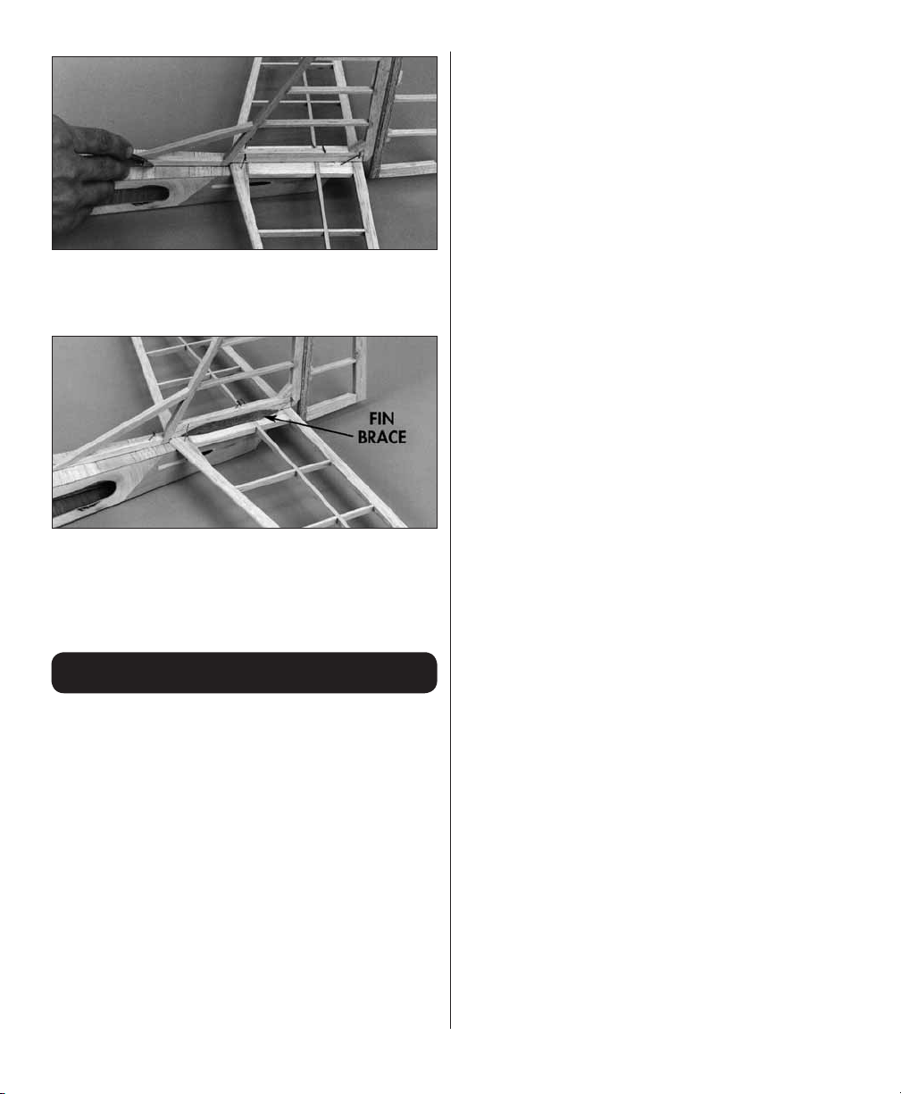
❏ 6. Make the fi n braces from the remaining 1/4"
balsa triangle stock. Make the braces 4" to 4-1/2"
long and bevel the ends. Position the braces on
the stab and trace their outlines on the fi n and stab
with a ballpoint pen.
Covering
Prepare for Covering
❏ 1. Inspect the entire model for glue joints that
don’t look strong and reinforce them with medium
or thin CA.
❏ 2. Remove the fi n (with the dorsal fi n) and stab
from the fuse. Final-sand the tail surfaces with
320-grit sandpaper being careful not to break any
of the tail ribs or “thin” the balsa too much in any
one area.
❏ 3. Slightly round the top and bottom corners of
the fuselage and the triangle stock “windows” with
your bar sander and 220-grit sandpaper. Sand the
fuselage so it is smooth and even. Fill all dents,
scratches and imperfect glue joints that may show
through the covering with HobbyLite fi ller.
❏ 4. Use medium CA to glue the die-cut 1/8"
plywood tail skid and balsa triangle reinforcements
to the bottom of the fuselage or glue the skid in
position after you cover the fuselage.
❏ 5. Test fi t the wing in the fuselage and adjust the
front and rear “windows” if necessary so the wing
will fi t between them.
Covering Sequence
Read the Covering Tips fi rst, then cover your
Butterfl y in this order:
Tail Surfaces:
1. Stab bottom right, then left
2. Stab top right, then left
3. Elevator ends
4. Elevator bottoms, then tops
5. Fin ends
6. Fin right, then left
7. Rudder right, then left
8. Triangular fi n reinforcements
Fuselage:
1. Bottom
2. One side, then the other
3. Top
4. “Windows”
5. Fuel tank hatch
6. Firewall
Wings:
1. Root (center) ends
2. Tips
3. Bottom inner panel
4. Bottom outer panel
5. Top inner panel
6. Top outer panel
Covering Tips
If this is the fi rst time you have covered a
model refrain from attempting a complicated
trim scheme. Add stripes, graphics and various
designs to your Butterfl y cut from different colors
of MonoKote fi lm, then iron them directly over the
28
Page 29

base color. Try just a single color base (usually a
lighter color such as white or yellow) with perhaps
a single stripe, your AMA number or some stick-on
graphics. A simple trim scheme will get you in the air
faster and look much better (not to mention give you
fewer headaches) than a model that was diffi cult
to cover because of a complicated trim scheme.
We will use the stabilizer as an example because
all of the techniques shown apply to the rest of
the Butterfl y too.
❏ 1. Here is a “rule of thumb” to keep in mind before
you begin: Wherever possible, apply the covering
so all seams face downward or rearward. This can
be done if you cover the bottom (of the wing, fuse,
stab, etc.) fi rst.
Start ironing at
Lines marked at
edges of fuse
the line and
work outward
Never cut the covering after you ir on it to the
wood except near the tips. Modelers who do
this may weaken the structure which could cause
it to fail during fl ight.
❏ 3. Use a straightedge to accurately trim the
covering near the LE and TE, but leave a little
“handle” around the corner and the tip so you can
pull the wrinkles out of the covering and stretch it
around the tip and corner as you heat it.
Stabilizer
Film
Cover only
to the lines
❏ 2. Cut the covering for one half of the bottom of
the stab so it is approximately 1" oversize. Use a
straightedge to cut the end that aligns with the lines
you drew indicating the fuselage. Use a Top Flite
MonoKote Iron with a Hot Sock to securely bond
the covering to the perimeter (LE, TE, tip, middle)
of the stab but do not fully shrink the covering at
this time.
Covering
❏ 4. Seal the front and rear of the covering to the
LE and TE, then heat the covering as you pull and
stretch it around the tip. It takes a little practice to
get all the wrinkles out so don’t be discouraged if
it doesn’t look perfect on your fi rst attempt (or the
second or third time). You can reheat and stretch the
covering many times. It helps to place the stab on
your workbench so the tip is over the edge. Place
a weight on top of the stab to hold it down. This
will allow you to pull the covering with one hand
and hold the iron in your other hand.
29
Page 30

❏ 5. Cut the excess covering from the tip with a
single-edge razor blade or a sharp hobby knife.
❏ 6. Cover the other side of the bottom of the stab
the same way.
the fi n reinforcement onto the covering, then take
the covering off the stab and cut out that portion
of the covering. This will allow you to glue the fi n
reinforcements directly to the bare wood and avoid
cutting the covering directly on the wood after
you iron it down. You can clean residual ink from the
covering with a cloth dampened with rubbing alcohol.
❏ 8. Iron the piece of covering you just “custom
cut” to the top of the stab, then cover the other
side the same way.
❏ 7. Temporarily position the top stab covering
and the triangle fi n reinforcement on the top of
the stab. Use a felt-tip pen to trace the outline of
❏ 9. Completely shrink the covering on the top
and bottom and thoroughly bond all the edges to
the frame.
❏ 10. Cover the triangle fi n reinforcements, then
trim the excess so it “overhangs” by approximately
3/32". This way all you have to do is glue them to
the fi n and stab and seal the edges with the iron.
30
Page 31

Join the Tail Surfaces
Join the Stab, Fin and Fuse
❏ 1. Apply a fi lm of 30-minute epoxy to the stab
and fuselage where they contact each other,
then position the stab on the fuselage. Use the
techniques described earlier (in Align The Stab)
to confi rm that the stab is aligned with the fuselage,
then use T-pins, weights or clamps to hold the stab
to the fuse until the epoxy fully cures. Use a cloth
dampened with alcohol to wipe away excess epoxy
before it cures.
❏ 2. Glue the fi n to the stab and fuse. Use a
90-degree triangle or a square to hold the fi n
perpendicular, then hold it in position with T-pins or
masking tape until the glue fully cures. If you require
a little working time to align the fi n use 30-minute
epoxy. Otherwise you may use 6-minute epoxy.
❏ 11. Use the methods described previously to
cover the rest of the model in the correct covering
sequence.
❏ 3. Test fi t the fi n reinforcements to the fi n and
stab. Take the reinforcements off the model, then
apply a bead of thick or medium CA to both “sides”
of one of the reinforcements. Immediately place the
fi n reinforcement on the fi n and stab and securely
hold it in position until the CA cures. Glue the other
reinforcement in position the same way.
31
Page 32
❏ 4. Use a MonoKote Iron or a Trim Seal Tool to
seal the perimeter of the reinforcements onto the
fi n and stab.
❏ 5. If necessary, cut 1/4" strips of MonoKote fi lm
and use your Trim Seal Tool to iron the strips in the
“corners” where the bottom of the stab meets the
fuse and the dorsal fi n meets the top of the fuse.
Hinge the Control Surfaces
IMPORTANT: Make sure you join the elevator
to the stab before you join the rudder to the fi n.
Cut the covering away from the slot
❏ 1. Use your hobby knife and a sharp #11 blade
to remove a small strip of covering from the hinge
slots to expose them.
The CA wicks along
the “tunnels” to the
entire hinge surface.
❏ 2. Drill a 3/32" hole in the center of all the hinge
slots to allow the CA to fully penetrate. This is best
done with a high-speed tool such as a powered
hand tool. If you use a drill, remove slivers of balsa
wood from the hinge slots with a hobby knife after
you drill the holes.
Temporary pin
to keep hinge
centered
❏ 3. Join the elevator to the stab with the hinges.
The horn plate of the stab (where the control
horn is fastened) should be on the right side. If the
hinges will not stay centered, insert a pin through
the center of the hinge, then join the surfaces and
remove the pins.
❏ 4. Confi rm that the ends of the elevator align with
the ends of the stab, that the hinges are centered
and there is approximately a 1/32" gap between the
TE of the stab and the LE of the elevator. A small
gap is desirable so you do not inadvertently glue
the elevator to the stab with residual CA.
❏ 5. Carefully apply 6 drops of thin CA to each
side of all the hinges. Keep a tissue handy to wipe
away excess CA. If you spill a few drops of CA
on the MonoKote fi lm you can use CA Debonder
(GPMR6039) to remove it. Or, wait until the CA
fully cures, then carefully lift it off with a hobby
knife blade.
Do not use accelerator on any of the hinges. Do
not glue the hinges with anything other than
thin CA and do not attempt to glue one half of
the hinge at a time with medium or thick CA.
They will not be secure and the controls could
separate while the model is fl ying.
❏ 6. Let the CA fully cure, then fl ex the elevator
several times to check the movement.
❏ 7. Hinge the rudder the same way as the elevator.
32
Page 33

Fuelproofing
Fuelproof areas that will be exposed to raw fuel
or exhaust residue. These include the fi rewall, the
entire fuel tank compartment, the underside of
the hatch and inside the fuselage around the wing
saddle area (the insides of the “windows” and
cabin sides). Use 30-minute epoxy (you may thin
the epoxy with alcohol so it is easier to brush on)
or fuelproof model airplane paint.
Final Hook-ups & Checks
Connect the Servos
❏ ❏ 3. Use the holes in the base of the control
horn as a guide to drill two 1/16" holes through
the elevator, then mount the control horn to the
elevator with two 2-56 x 1/2" screws and the control
horn plate.
The nylon parts in this photo have been dyed black
for illustration clarity.
❏ ❏ 1. Cut a 36" wire rod (included) to a length of
30" (including the threaded end). Connect a nylon
clevis to a nylon control horn, then thread the clevis
approximately 20 turns onto the rod.
RIGHT WRONG
❏ ❏ 2. Use a new #11 blade to cut the covering
from the pushrod guide tube exits in the rear of the
fuselage, then insert the pushrod into the elevator
guide tube. Position the control horn on the elevator
in the location indicated on the plan so that the
holes in the control horn align with the hinge gap
as shown in the sketch.
❏ ❏ 4. Make another pushrod assembly and mount
the control horn to the rudder the same way as
the elevator.
❏ ❏ 5. Follow the instructions included with your
radio to hook-up and center all servos. Center
the elevator servo arm, then use a felt-tip pen to
mark the wire pushrod where it crosses the holes
in the arm.
33
Page 34
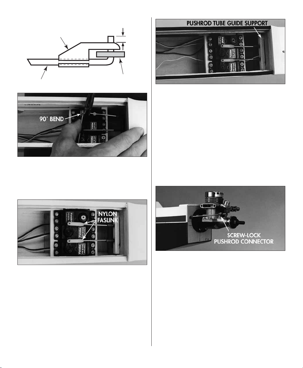
FasLink
1/16"
2-56 (.074") Pushrod Wire
Servo Horn
❏ ❏ 6. Disconnect the clevis from the elevator horn,
then make a 90-degree bend in the pushrod at the
mark. Snap a FasLink™ Pushrod Keeper (included)
onto the pushrod. Cut the wire so it protrudes from
the FasLink by 1/16" as shown in the sketch.
❏ ❏ 9. Glue the forward pushrod guide tube support
to F-7, then glue the pushrod guide tubes to the
support with medium or thin CA.
❏ 10. Install the engine mount on the fi rewall. Attach
the engine to the mount.
❏ 11. Sand the 12" outer throttle guide tube so
glue will stick. Insert the tube through the holes
in the fi rewall and F-6. Cut a 36" rod (threaded
one-end) to a length of 17" including the threaded
end. Thread a nylon clevis onto the wire pushrod,
then install the pushrod so the non-threaded end
protrudes from the fi rewall.
❏ ❏ 7. If necessary, enlarge the holes in the servo
arm with a hobby knife or a 5/64" drill bit, then
connect the pushrod to the elevator servo arm
from the bottom and secure it with a FasLink.
Adjust the clevis so the elevator is centered, then
fi t a silicone retainer on the clevis and connect the
clevis to the elevator control horn.
❏ ❏ 8. Connect the rudder pushrod to the servo
and rudder the same way.
❏ 12. Connect the clevis to the servo arm, then
connect the front of the throttle pushrod to the
carburetor arm with a Great Planes Screw-Lock™
Pushrod Connector (included). The pushrod may
require a couple of small bends to align with the
pushrod connector. Cut off the excess wire so
approximately 1/4" protrudes from the connector.
❏ 13. Glue the outer throttle pushrod guide tube
to the fi rewall and F-6 with thin CA.
34
Page 35

❏ 14. Install the fuel tank and connect the fuel tubes.
❏ 15. Install the fuel tank hatch with the #2 x 3/8"
screws. The hatch should secure the tank, but if
necessary, place extra foam around the fuel tank
so it cannot shift during fl ight.
Mount the Landing Gear
❏ 1. Cut the covering from the landing gear holes
on both sides of the fuselage, then fi t the landing
gear in the rails.
❏ 3. Cut the die-cut 1/8" plywood top landing
gear plate in half, then mark the location where
the landing gear wire contacts both plates. Use a
hobby knife or a powered hand tool to cut a notch
in both plates to clear the landing gear.
❏ 4. Thoroughly roughen the portion of both landing
gear wires that will be inside the fuselage with
coarse sandpaper. Use plenty of 30-minute epoxy to
glue the top landing gear plates to the 1/16" strips
you positioned in step 2.
❏ 5. Mount a 2-1/4" wheel on each landing gear wire
with 5/32" wheel collars (not included, GPMQ4306)
on both sides of the wheels.
❏ 6. Connect the servo cords and the switch to
your receiver, then wrap the receiver and battery
pack in foam.
❏ 2. Use the 1/16" plywood leftover from the W-1
root ribs to make two 1/16" x 3/8" x 2-3/4" strips.
Chamfer the corner of one of the strips so it will
clear the “upright” part of the left landing gear in
the right side of the fuse. Glue the strips to the
top of the landing gear rails with 6-minute epoxy.
Finish Radio Installation
Note: Because the Butterfl y is a three channel
model (where the steering function is the rudder not
ailerons) connect the rudder servo to the “aileron”
channel of your receiver.
35
Page 36
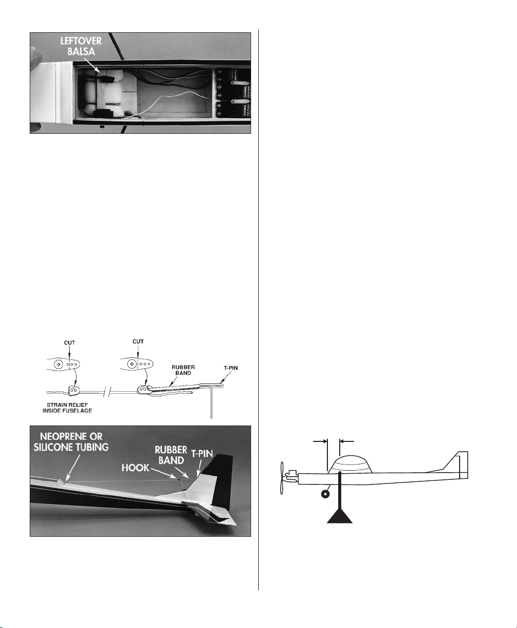
❏ 1. Temporarily position the battery pack and
receiver inside the fuselage in a location that will
achieve balance at the Center of Gravity (C.G.)
shown on the plan and described in the Balance
Your Model section that follows. In our prototype
a 500mAh fl at pack wrapped with 1/4" foam fi t
“snugly” underneath the fuel tank supports shown
in step 16 on page 26.
❏ 2. Cut the covering from the holes in the fuselage
sides for the wing dowels, then glue the dowels
in position with medium CA. Fuelproof the ends
of the dowels with thin CA, epoxy paint or epoxy.
❏ 3. Mount the on/off switch on the side of the
model that is opposite the engine exhaust in a
location that will not interfere with the receiver or
pushrods.
hook from an unused servo arm as shown in the
sketch. Never shorten the antenna wire.
Mount the Wing
❏ 1. Apply 1/16" thick Great Planes Single-Sided
Foam Tape (GPMQ4422) to the wing saddle of
the fuselage.
❏ 2. Poke a hole through the covering where you
drilled the 1/16" holes in the bottom spar of both
wing halves for the #2 x 3/8" screws. Pack the
holes with 6-minute epoxy, then immediately install
the screws.
❏ 3. Join both wing halves with the wing joiner rod,
then secure the wing halves together by wrapping
a couple of rubber bands around the screws in the
bottom spar.
❏ 4. Place the wing on the fuselage, then hold it in
place with two or four #64 rubber bands. When it
is time to fl y your Butterfl y, you should secure the
wing with eight rubber bands and cross the last two.
Balance Your Model
This section is IMPORTANT and must NOT be
omitted. A model that is not properly balanced will
be unstable and possibly unfl yable.
❏ 4. Route the receiver antenna through the
antenna tube (if you installed one) or through the
top of the fuselage to a T-pin inserted into the
leading edge of the fi n. Make a strain relief and a
❏ 1. Check the balance point with all components
installed in the model and the fuel tank empty.
Attach the wing to the fuselage with a few rubber
bands, then accurately mark the balance point
on the bottom of both wing halves next to the
fuselage. The balance point is shown on the plan
and is 3-3/16" (81mm) aft of the leading edge.
3-3/16"
❏ 2. Lift the model with your fi ngers at the balance
point or make a simple stand as shown in the
sketch. If the tail drops, shift the receiver and/or
battery pack forward (if possible) to balance the
model. If the nose drops, shift the receiver and/or
36
Page 37

battery pack aft. If possible arrange the battery
pack and receiver to achieve balance but make
sure they remain secure in the fuselage so they
cannot shift during fl ight or a rough landing. If you
must add additional weight to the nose or tail of
the Butterfl y to achieve balance use Great Planes
adhesive lead weights (GPMQ4485). An alternative
to stick-on nose weight (if your model is tail heavy)
is a Great Planes brass spinner nut (GPMQ4640).
It has 1/4-28 threads so it will fi t most engines.
Set the Control Throws
Measure the throws at the widest part of the
trailing edge of the rudder and elevator. After
a few fl ights you may change the throws to suit
your fl ight style or the weather conditions.
We recommend the follo wing control surface
throws:
Elevator: 3/4" up and down
Rudder: 1-1/2" left and right
Throttle: Set the throttle so that at “high stick”
the carburetor barrel is fully open and at low
stick with full to half throttle trim, the carburetor
barrel is nearly closed. At this position the engine
should run reliably at a low RPM (idle). To shut
the engine off, decrease the throttle trim tab.
More movement
control throw, move the clevis on the control horn
outward and/or move the pushrod on the servo arm
inward. Combinations of the above arrangements
will provide the control throw you require. Of course,
if your transmitter has ATV (adjustable travel
volume), use them to fi ne-tune the control throws.
Preflight
At Home
Balance Y our Propellers
Balancing the propeller seems like one of those
things that you can skip, but many problems are
the result of vibration caused by an unbalanced
propeller. Nuts and bolts can vibrate loose and
vibration can damage delicate radio components
inside your receiver and servos. Vibration can even
damage the delicate glow plug element which could
result in an engine that is diffi cult or impossible
to start. Purchase a Top Flite Precision Magnetic
Balancer™ (TOPQ5700) or a Great Planes fi ngertip
prop balancer (GPMQ5000) to accurately balance
your propellers.
Charge Y our Batteries
Follow the battery charging instructions in the
instruction manual that came with your radio control
system. You should always charge your batteries
the night before you fl y.
Less
movement
Moving the clevis outward on the servo arm
results in more pushrod movement.
More
movement
More
throw
More
Moving the clevis inward on the control horn
results in more throw.
throw
The closer the clevis is to the base of the control
horn on the control surface and/or the further the
pushrod is from the center of the servo arm, the
more control throw you will have. To decrease
Ground Check Your Model
Inspect all nuts, screws and wheel collars. Make
sure you install the screw that holds the servo
arm onto the servos and the servo cords are
securely connected to the receiver.
If you are not thoroughly familiar with R/C models,
ask an experienced modeler to inspect your radio
installation and make sure the control surfaces
respond correctly. The engine must be “brokenin” according to the engine manufacturer’s
recommendations for break-in. Refer to the Engine
Safety Precautions on page 42 before you start
your engine. After you run the engine on the model
make sure all screws remain tight, the hinges are
secure and the prop is on tight.
37
Page 38

Gather Y our Tools
Assemble a simple fl ight kit (a shoe box is fi ne
to start with) which should include a 1-1/2 volt
starting battery and glow plug clip (or ni-starter),
a “chicken stick” for fl ipping the prop, fuel and fuel
pump or other means of fi lling the tank, a couple
of small screwdrivers, #64 rubber bands, spare
props (balanced) and glow-plugs, a wrench for the
propeller nut, a needle-nose plier or hemostats
and some CA for fi eld repairs. In addition to tools,
you should also take along some paper towels and
spray window cleaner to remove exhaust residue
from the model (and your hands) after each fl ight.
Store fuel-soaked rubber bands in a container with
talcum powder or corn starch to absorb the oil.
At the Flying Site
Range Check Your Radio
Check the operational range of the radio before
the fi rst fl ight. Bef ore you turn your radio on, the
fi rst thing you always must do is make sure
no one else is on your frequency (channel).
Most model fl ying fi elds utilize frequency control
so familiarize yourself with their system. Collapse
your transmitter antenna and turn on the transmitter,
then the receiver (preferably the receiver should
never be on by itself). You should be able to walk at
least 100 feet away from the model and still have
control. Have an assistant stand by your model and
tell you what the control surfaces are doing while
you operate them from the transmitter.
Repeat this test with an assistant holding the model
and the engine running at v arious speeds. If the
control surfaces do not always respond correctly,
don’t fl y! Find and correct the problem fi rst. Look
for loose servo connections or corrosion, loose
fasteners that may cause vibration, a defective on/
off switch, low battery voltage or a defective cell, a
damaged receiver antenna or a receiver crystal that
may have been damaged from a previous crash.
Store model fuel in a safe place away from high
heat, sparks or fl ames. Do not smoke near the
engine or fuel as it is very fl ammable. Engine
exhaust gives off a great deal of deadly carbon
monoxide so do not run the engine in a closed
room or garage.
Get help from an experienced modeler when you
learn to operate engines.
Use safety glasses when you operate model
engines.
Do not run the engine near loose gravel or sand;
the propeller may throw loose material in your
face or eyes.
When you start and run the engine keep your face
and body as well as all spectators away from the
plane of rotation of the propeller.
Keep loose clothing, shirt sleeves, ties, scarfs,
long hair or loose objects away from the prop. Be
conscious of pencils, screwdrivers or other objects
that may fall out of your shirt or jacket pockets.
Use a “chicken stick” or electric starter and follow
the instructions to start your engine.
Make certain the glow plug clip is secure so that
it will not pop off or get into the running propeller.
Ask an assistant to hold the model from the rear
while you start the engine and operate the controls.
Make all engine adjustments from behind the
rotating propeller.
The engine gets hot! Do not touch the engine during
or immediately after you operate it. Make sure fuel
lines are in good condition so fuel will not leak onto
a hot engine and cause a fi re.
To stop the engine, close the carburetor barrel
(rotor) or pinch the fuel line to discontinue the fuel
fl ow. Do not use your (or any body else’s) hands,
fi ngers or any body part to stop the engine (sorry,
we had to say that because of liability). Never throw
anything into the prop of a running engine.
Flying
Engine Safety Precautions
NOTE: Failure to follow these saf ety precautions
may cause severe injury to yourself and other s.
Find a Safe Place to Fly
The best place to fl y your R/C model is at an AMA
(Academy of Model Aeronautics) chartered club
38
Page 39

fi eld. Ask your hobby dealer or the AMA if there
is a club in your area and join it (the address and
telephone number for the AMA is listed on page 3
of this instruction book). Club fi elds exist to make
your R/C fl ying safe and enjoyable. We recommend
that you join the AMA and a local club so you may
have a safe place to fl y and insurance in case of
a fl ying accident.
If a club fl ying site is not available, fi nd a large,
grassy area at least 6 miles away from houses,
buildings, streets and other R/C activity like boats
and cars. Avoid fl ying R/C models near traffi c or
areas such as parks, school yards, offi ce building
lawns, etc. that may attract unrestrained observers
(wild kids). If you are a beginner, you are busy
enough concentrating on your model without having
to answer lots of questions and performing crowd
control.
We highly recommend that you get an experienced
modeler to assist you with your fl ight training. An
experienced modeler can take your Butterfl y up for
the fi rst time and make sure it performs correctly,
then give you valuable fl ight instruction. He can hand
you the transmitter when the Butterfl y has climbed
to a safe altitude or connect your transmitter to his
if both of your systems have trainer cord or “buddy
box” capability. Assistance from an experienced
modeler will make your modeling “career” progress
faster (and cheaper). We do, however realize that
some modelers are determined to learn on their
own or are not in a location where an instructor or
fl ying club is available. Therefore, we have provided
the following information to give you an idea of
what to expect on your fi rst fl ight with your Butterfl y.
Both fl yers who plan to set out on their own and
fl iers who will have the help of an instructor should
carefully read the following information.
Takeoff
First fl ight attempts should be reserved for calm
days when the wind is less than fi ve to seven mph.
Although the Butterfl y does have landing gear, it is
really intended only for landing so you should hand
launch the Butterfl y. Actually, this makes takeoff a
little easier since you do not have to “stay on the
runway” or worry if the wind is prevailing down the
runway or not. Just hand launch the Butterfl y into
the wind. If you are at a model fl ying fi eld check
with veteran club members to see if this is an
acceptable practice – some clubs specify a fl ight
path no matter the crosswinds.
Always launch (takeoff) and land into the wind. Start
the engine and have your assistant hold the model
over head. Check the operation of all controls just
before takeoff. This will eliminate the possibility of
forgetting to turn on the receiver switch (it happens)
or overlooking reversed or disconnected controls.
Advance the throttle. When you are ready for launch
give an affi rmative nod to your helper. You should
stand behind or to the side and behind the model
when your assistant launches it. He should carefully
run at a fast pace but only needs to take a few
strides, then fi rmly launch the model in an overhead
motion (like a javelin throw). He should throw the
model at a level or slightly nose-up attitude so the
model can climb gently under its own power. The
Butterfl y can only fl y and climb so fast so if your
helper throws the model too hard or at too great
of an angle, it may stall (stop fl ying) requiring time
to gain airspeed before it can resume a climb. Just
a little help on the hand launch is all your Butterfl y
needs – just remember it’s named the “Butterfl y.”
There is no exact way to tell you how much “up”
elevator to apply when your assistant launches
your Butterfl y. It’s rather a balancing act so be
ready to “give it what it needs” to start a g entle
climb. As long as your Butterfl y is gaining altitude
you’re O.K. (unless you are at a small fl ying site
with obstacles to clear). If the Butterfl y appears to
climb too steeply and looks as though it is going
to stall, momentarily apply a little down elevator to
point the nose down and regain air speed. Once
airspeed has returned, resume a gentle climb. The
most common mistake of all modelers beginner
and expert alike is not controlling the urge to “get
away from the ground” and “horsing” the model into
the sky. As explained earlier, this only results in a
stall, if not a terrible looking (and risky) departure.
The idea is not to put the Butterfl y into orbit but to
reach a safe altitude where you can execute your
fi rst turn. All of this is going to happen quickly so
try to keep your mind clear and react.
39
Page 40

Flight
Allow the Butterfl y to climb as gently or steeply as
required and you are comfortable with, then execute
your fi rst turn. Make a right or a left 180-degree turn
(whichever direction will keep you from fl ying over
head or over obstacles). Initiate the 180-degree turn
by applying a little rudder in the direction you wish to
turn, then apply a little up elevator to keep the nose
level. You will fi nd that once the turn is initiated, no
more rudder is required to hold the turn but opposite
rudder may be required to stop the turn and return
the Butterfl y to a straight and level attitude.
At this time the Butterfl y is fl ying “down wind” so it will
gain speed and perhaps loose a little altitude. Just
apply a little up elevator to maintain altitude or gain
altitude if you prefer. Also, be aware that at this point
the Butterfl y will be “facing you” (not facing away
from you as it was when you took off) so to make the
model move to your right (the Butterfl ies’ left) you will
have to move the rudder stick to the left. Nothing has
changed except your perspective. Some beginners
fi nd it helpful to turn slightly away from the model and
fl y it “over their shoulder” so they are facing almost
the same direction as the model. Some instructors
tell their students to “put the stick under the low wing
when the model is fl ying toward you.” Luckily, the
Butterfl y will react slowly enough so you should be
able to fi gure it out if you have enough altitude.
Your next turn will be into the wind so it will be a
little easier to maintain altitude and complete the
turn. Apply rudder in the direction required to initiate
the turn. Keep fl ying a “racetrack pattern” while you
maintain altitude and make small corrections (as small
as possible) to keep the desired heading.
Due to the nature of the design (a powered sailplane)
the Butterfl y should gently climb at all times but, if it
seems to climb too rapidly, apply a little “down trim” to
decrease the rate of climb. If your Butterfl y requires
you to hold up elevator all the time to get it to climb,
apply a little “up trim” to resume a gentle climbing
tendency. Once you have become comfortable with
the rate of climb and altitude of your Butterfl y, throttle
back to about 2/3 or 1/2 throttle to keep from climbing
out of sight. Actually, the purpose of the engine on
your Butterfl y is not to get it from “point A to point B”
or for “zipping around” (like traditional models), but
the engine is for gaining altitude to get your Butterfl y
high enough to let you fl y it, react and learn how to
correct mistakes and guide it through the air. Continue
fl ying the “race track pattern” making adjustments to
altitude, heading and speed.
Landing
Landing your Butterfl y is the easy part because by
now you have had a few minutes of fl ying time under
your belt and the “butterfl ies” (sorry, we couldn’t resist)
should be all gone. Make a pass over the landing area
(remember – always land into the wind) and reduce the
throttle to about 1/4. Allow your Butterfl y to descend
as it approaches the fl ying fi eld. Hold the throttle at
1/4, then slowly advance the throttle as the Butterfl y
passes by at an altitude of approximately 10 to 30
feet. Make a few more practice landing approaches
adjusting the heading and altitude as you pass by.
Finally, decrease the throttle to idle (with the throttle
trim adjusted per the control throws) and allow the
Butterfl y to descend. As the Butterfl y reaches an
altitude of approximately 10’ to 20’ gradually apply
enough up elevator to maintain a gradual, slow
descent (but not enough to climb) until it almost
reaches the slowest fl ying speed possible. At this point
the Butterfl y should be only about 1 foot off the ground.
Allow the Butterfl y to continue down the fl ying fi eld
until it looses speed and fi nally touches the ground.
You should attempt your fi rst landings with just a few
“clicks” of extra power on the throttle trim to make
sure you do not stall the model too early at too high
of an altitude. You do not have to land the Butterfl y
upon the fi rst attempt. If for some reason (you have
not “scrubbed off” enough speed, you are too far
away, there is a sudden wind gust) you have trouble
with your landing approach, just add power, climb
out and try it again.
Remember, your Butterfl y is a motor glider so it is
going to react slowly (ideal for beginners) and requires
lots of space to maneuver.
We hope you have fun with your Butterfl y and that
your fi rst attempt at R/C airplanes is successful!
40
 Loading...