

Page 1
PARTS LIST
❏ 1 Instruction sheet
❏ 1 Instrument panel
❏ 1 Instrument panel lens
❏ 1 Seat back
❏ 1 Seat bottom
❏ 1 Luggage tank top
❏ 1 Luggage tank bottom
❏ 2 Luggage tank joiner
❏ 1 Elastic seat belts
❏ 1 Fiberglass tape
❏ 1 Small parts bag: bomb release wire, bomb release
mechanism,
dowels, pins, 2- #2 x 3/8" screws, 4- #4 x 5/8" screws
TOOLS AND SUPPLIES
❏Thin CA (Great Planes
®
Pro™recommended)
❏ 6-Minute epoxy
❏ Canopy glue
❏ Hobby knife and #11 blades
❏ Plastic filler putty or Bondo
®
❏ 80, 220 and 400-grit wet/dry sandpaper
❏ Selection of small paint brushes
❏ Model enamel paint – (Testors enamel recommended)
❏ Needle nose pliers
❏ Wood stain
❏ Gloss varnish or polyurethane
❏ Clear silicone adhesive
❏ 1. Follow the embossed “cut lines” on each part with a shar p
hobby knife to score the plastic. Gently flex the plastic along the
score to break the scrap from around the edges. Sand each par t
with progressively finer grades of sandpaper to smooth the edges.
Finish the part off by wet sanding the entire exposed surface with
400-grit paper to give the plastic a “tooth”for better paint adhesion.
❏ 2. Use thin CA to glue the seat back to the top surface of the
seat bottom, flush with the rear edge.
❏3. Using sketch #1 as a template, bend the wire to create a “U”
shape as shown in the above image.The center section is 1/4"
wide.
❏ 4. Using sketch #2 as a template, bend the legs in opposite
directions
as shown in the above image.The center section has a
height of 1/4"
.
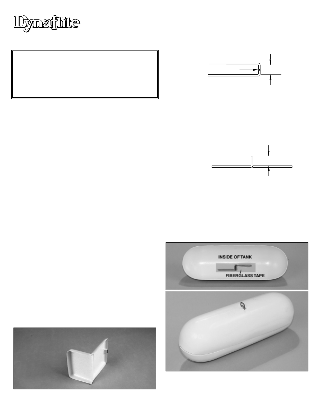
❏ 5. Cut out the marked hole on the luggage tank top. Roughen
the inside of the tank for about a 2" area around the holes with 80-
grit sandpaper.Glue the wire to the inside of the tank with thin CA.
Use 6-minute epoxy to glue the furnished strip of fiberglass cloth
over the clip to reinforce the joint.
]
SCALE COCKPIT KIT – ASSEMBLY INSTRUCTIONS
Congratulations for being one of those modelers who takes pride in
flying a truly finished model; inside and out! The little bit of extra effort
required to assemble and install this accessory kit will be rewarded by
your personal satisfaction and the applause of your buddies. We have
provided the basic ingredients – you provide the imagination to finish
the details to your liking.All it takes is a couple of evenings and you will
have an even better looking model. Have fun and try to be gracious
when accepting the compliments at the field!
Copyright © 2001
Printed in USA – FBCKP01 V1.1
™
88884444"""" FFFFuuuunnnn SS
SSccccaaaalllleeee FFFFllllyyyy
BB
BBaaaabbbbyyyy
Sketch #1
/4" [6.35mm
Sketch #2
1/4" [6.35mm]
Page 2
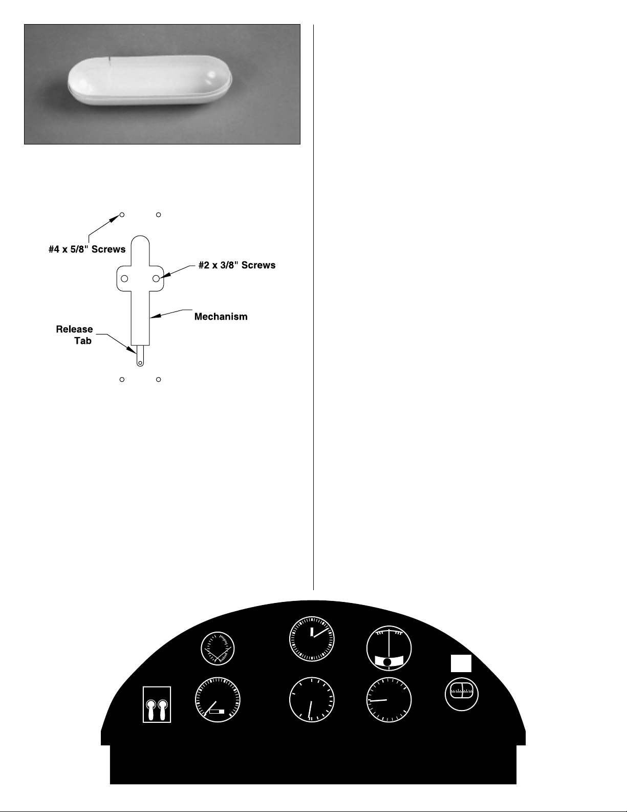
❏ 6. Tr im the 3/8" x 10" strips of plastic to fit around the inside of
the bottom half of the luggage tank. Center the strips on the inside
edge of the tank bottom to form a flange and glue them in position
with thin CA.
❏ 7. Glue the top of the tank to the bottom by “wicking” thin CA
around the joint between the two halves.Fill any gaps around the
seam with plastic filler putty or Bondo.Sand the seam smooth with
progressively finer grades of sandpaper ending by wet sanding
with 400-grit. Screw the tank mount to the centerline of the wing
with two #2 x 3/8" screws, approximately centered over the spar
(use the template above to properly install the luggage tank).
Use
the #4 x 5/8" screws to hold the luggage tank in position.
❏ 8. Paint the seat and luggage tank to your liking. If you will fly
with the luggage tank attached, be sure to use fuelproof paint to
protect the finish from exhaust oil. Cut the elastic seat belts to fit
your pilot figure. Glue them to the seat back notch and the seat
bottom with CA.
❏ 9. Apply a 1/4" bead of clear Silicone adhesive to the inside
edges of the seat bottom.Install the seat in the cockpit and hold or
weight it in position. The Silicone will flow down onto the floor
inside the seat and secure it in place. Carefully apply a few drops
of thin CA to the seat back edges, allowing the CA to “wic k”around
the joint between the seat and the aft cockpit bulkhead. Hold it in
position until the CA cures.
❏10. Before you add the instruments and clear Butyrate, sand the
laser-cut instrument panel smooth with 400-grit sandpaper. Apply
a wood stain to bring out the color of the grain. Finish the
instrument panel with Varnish or Polyurethane for a high gloss.
❏ 11. Trace the outline of the instrument panel onto the clear
plastic sheet with a sharp hobby knife, to score the plastic.Flex the
plastic to break away the e xcess material.Sand the edges smooth.
Glue the clear plastic to the back of the instrument panel with
“canopy glue” or epoxy. Note: The plastic will stick better if the
contact surface is lightly sanded, Be careful NOT to scratch the
exposed “lens” areas.
❏ 12. Cut the paper instruments to fit the back of the instrument
panel (IP). Glue them to the clear plastic with Canopy glue.
❏ 13. Cut and glue a piece of scrap balsa to the back of the
instrument panel assembly. Use pliers to push the control knobs
(pins) through the front of the panel. Apply a spot of CA on the
back of the IP to secure them in position.Add other surface details
as desired. Attach the instrument panel to the model with Silicone
adhesive.
❏ 14. Paint the dowel “control-stick” with aluminum enamel. After
the paint has dried, wrap one end with a few layers of electricians
tape to form a hand grip. Mark the location of the control-stick on
the cockpit floor then drill a 1/16" diameter hole through the
marked spot. Carefully drill a 1/16" diameter hole about 3/8" deep
into the bottom of the control-stick. Install a #2 x 3/8" sheet metal
screw from beneath the cockpit floor so that it just protrudes into
the cockpit area. Apply a dab of epoxy to the bottom of the control
stick.Twist the control stick onto the protruding screw and secure
it with a screwdriver.
If you have questions or comments write or call:
DYNAFLITE
P.O.Box 788
Urbana, IL 61803
(217) 398-8970
Luggage T ank
Template
Release
0
9 l
240
60
200
40
160
20
120
l5
20
l0
25
RPM
30
5
21
9649
0
35
28
73
ALT
6
4
5
60
80
40
100
120
KNOTS
20
140
0
l
CLIMB
DESCENT
l
IIVMINX IIVMINX
IIVMINXIIVMINX
IIVMINX IIVMINX
IIVMINX IIVMINX
IIVMINX IIVMINX
2
2
36
 Loading...