

Page 1
TM
TM
•
Simple
Ent
ry Level
Construction
• Stable Flight Characteristics
• Excellent R/C Trainer
READ THROUGH THIS INSTRUCTION MANUAL FIRST. IT CONTAINS
IMPORTANT INSTRUCTIONS AND WARNINGS CONCERNING THE ASSEMBLY
AND USE OF THIS MODEL.
Instruction Manual
WARRANTY
Dynaflite guarantees this kit to be free from defects in both material and workmanship at the date of
purchase. This warranty does not cover any component parts damaged by use or modification. In no
case shall Dynaflite's liability exceed the original cost of the purchased kit. Further, Dynaflite reserves
the right to change or modify this warranty without notice. In that Dynaflite has no control over the
final assembly or material used for final assembly, no liability shall be assumed nor accepted for any
damage resulting from the use by the user of the final user-assembled product. By the act of using
the user-assembled product, the user accepts all resulting liability. If you are not prepared to accept
the liability associated with the use of this product, return this kit immediately in new and unused
condition to the place of purchase.
WANDP03 Printed in USA
MADE IN
Page 2
I
ntroduction.......................................................2
Precautions........................................................3
Preparations.......................................................3
Required
Suggested Building Supplies........................3-4
Optional Building Supplies...........................4
Building
Glossary of Terms Used in
This
Manual
Die-Cut
Build the Horizontal Stabilizer
and Elevator..................................................8-10
Install the Hinges
Finish
the
Build the Fuselage........................................11-15
Install the Hatch
Build the
Build the
Final
Wing
Align
the
Balance the
Finishing
Final Assembly............................................22-23
Assemble
Install the Radio
Set
the Control
Balance
Pre-Flight..........................................................27
Charge the
Ground
Range Check
Flying
First
Landing......................................................28
Items
..............................................3
Notes.................................................4-5
and
Plans.....................................
Patterns..................................................7
.........................................10-11
Fin
and
Rudder..................................11
...........................................15-16
Wing
Root
Panel............................16-18
Wing
Tip Panel
Assembly
Stabilizer
Model
.....................................................21-22
the
Pushrods
System
Throws
Your
Model.....................................26-27
Batteries
Check
Your
...............................................................28
Flight...................................................28
..............................18-20
........................................20
to
the
Wing
.........................21
Laterally..............................2
................................23-24
...............................24-25
......................................26
....................................27
Your
Model...........................27
Model.............................28
5-6
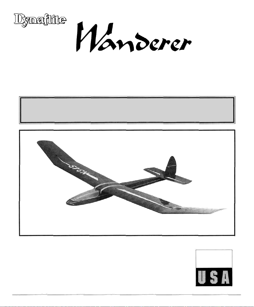
The 72" version of the Wanderer was developed by
Mark Smith as a first-time building and flying
project. Since its introduction in 1975, over 85,000
kits have been produced. Over the years the
Wanderer has been updated with many changes
recommended to us by first-time builders. The
Wanderer still has the same basic aerodynamics as
the original kit, but has been simplified to make
assembly quicker and easier.
At Dynaflite we take pride in offering kits that are
simple and straightforward to build and provide
value for your modeling dollar.
To make your R/C modeling experience totally
enjoyable, we recommend that you get assistance
with your first flights from an experienced,
1
knowledgeable modeler. You'll learn faster and
avoid risk to your model before you're truly ready to
solo. Your local hobby shop has information about
flying clubs in your area whose membership
includes qualified instructors.
You can also contact the national Academy
Model Aeronautics (AMA), which has more than
2/500 chartered clubs across the country. We
recommend you join the AMA, which will provide
you with insurance coverage at AMA club sites and
events. AMA Membership is required at chartered
club fields where qualified flight instructors are
available. Contact the AMA at the address or tollfree phone number below:
of
Congratulations on your choice of this kit for your
next project. If you are new to radio control
modeling, we would like to take a minute to give
you some background on the Wanderer.
Academy of Model Aeronautics
5151 East Memorial Drive
Muncie,IN 47302
(800) 435-9262
Fax (765) 741 -0057
Internet address : http://www.modelaircraft.org
2
Page 3

1. You must assemble the sailplane according to the
instructions. Do not alter or modify the model, as
doing so may result in an unsafe or unflyable model.
In a few cases the instructions may differ slightly
from the photos or plan. In those instances the text
should be taken as correct.
2. You must take time to build straight, true and strong.
3. You must install all R/C and other components so
that the model operates properly on the ground and
in the
air.
4. You must test the operation of the model before
the first and each successive flight to insure that all
equipment operates correctly. You must also make
certain that the model has remained structurally
sound, especially after a rough landing.
NOTE: We, as the kit manufacturer, provide you
with a quality kit and great instructions, but
ultimately the quality and flyability of your
finished model depends on how you assembled it;
therefore, we cannot in any way guarantee the
performance of your completed model and no
representations are expressed or implied as to the
performance or safety of your completed model.
REQUIRED ITEMS
These are the items not included with your kit; you
will need to purchase them separately. Items in
parentheses (GPMQ4243) are suggested part
numbers recognized by distributors and hobby
shops and are listed for your ordering convenience.
GPM is the Great Planes® brand, TOP is the Top
Flite®
brand,
is the Dynaflite™ brand.
HCA
is
the
Hobbico®
2 - 4 channel radio with two standard servos.
Top Flite MonoKote® (Approximately 2 rolls)
1/4" Latex Foam Rubber (HCAQ1050)
Switch and Charge Jack (GPMM1000)
2 Meter Up-Start (DYNP8305) or Standard
Hi-Start(DYNP8301)
brand
and DYN
SUGGESTED BUILDING
SUPPLIES
We recommend Great Planes Pro™ CA and Epoxy
glue.
Please inventory and inspect all parts carefully
before starting to build. If any parts are missing,
broken or defective, or if you have any questions
about building or flying this model, please call us
at (217) 398-8970 and we'll be glad to help. If
you are calling for replacement parts, please
look up the part numbers and have them ready
when calling.
2 oz. Pro CA (Thin, GPMR6003)
1 oz. Pro CA- (Thick, GPMR6014)
6-Minute Pro Epoxy (GPMR6045)
30-Minute Pro Epoxy (GPMR6047)
4 oz. Pro Wood Glue (GPMR6161)
Hand or electric drill
Sealing Iron (TOPR2100)
Hobby saw
3
Page 4
SUGGESTED BUILDING
SUPPLIES, CON'T.
Hobby Knife (HCARO 105)
#11 Blades
Pliers (Common and Needle Nose)
Screw driver (Phillips)
T-pins(HCAQ5150)
60" Retractable Tape Measure (HCAR0478)
Straightedge With Scale
Masking Tape (TOPR8018)
Sandpaper (coarse, medium, fine grit)
Easy-Touch™ Bar Sander (or similar)
Plan Protector (GPMR6167)
Lightweight Balsa Filler such as Hobbico®
HobbyLite™ (Hobbico HCAR3400)
IsopropyI Rubbing Alcohol (70%)
Ballpoint Pen
90° Building Square
Heavy Sewing Thread (any color)
#64 Rubber Bands
Drill bits: 1/16", 5/64", 3/32", and 3/16"
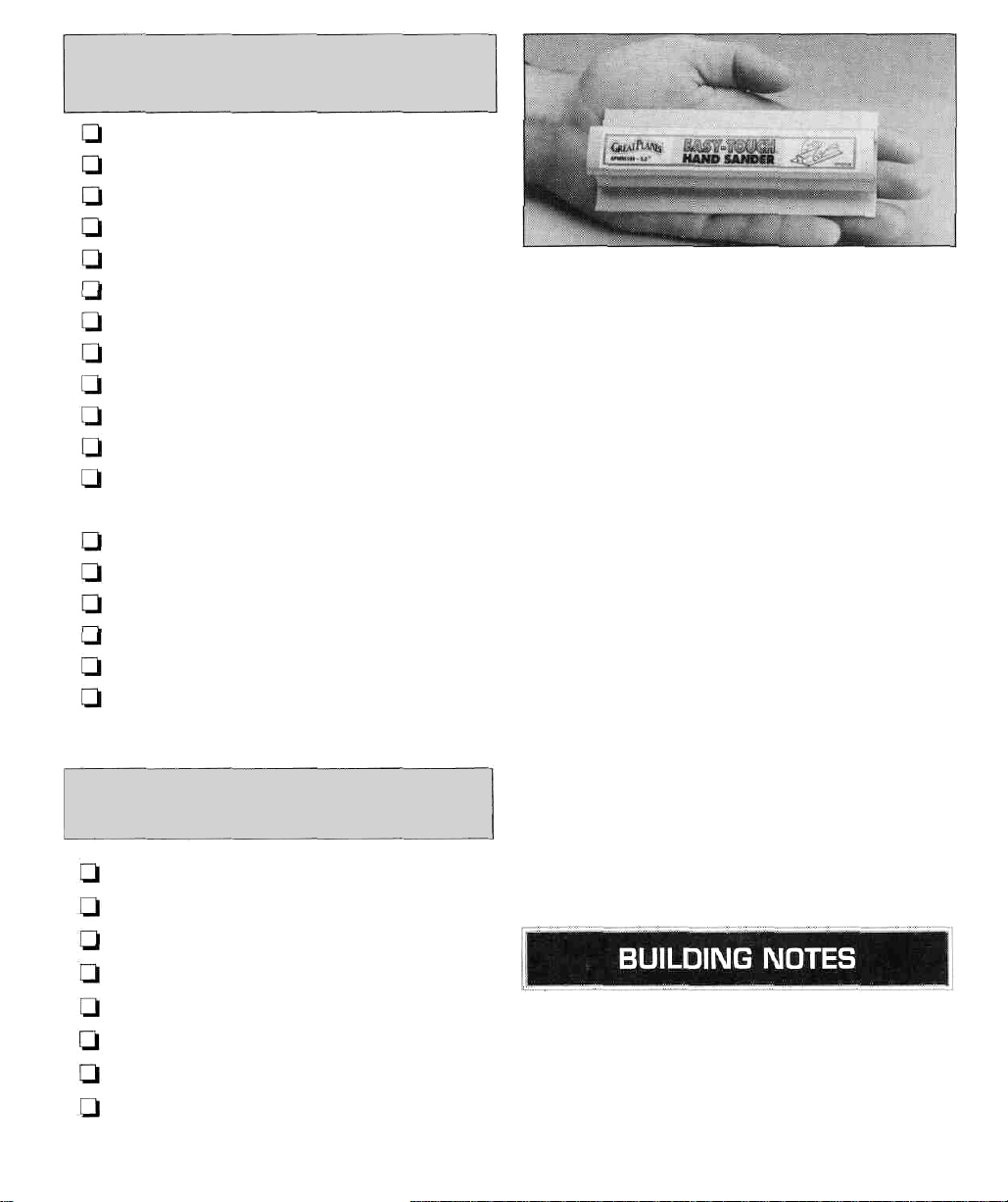
Great Planes Easy-Touch Bar Sanders are made
from lightweight extruded aluminum and can be
found at most hobby shops. They are available in
five sizes - 5-1/2" (GPMR6169) for those tight,
hard to reach spots; 11" (GPMR6170) for most
general purpose sanding; and 22" (GPMR6172),
33" (GPMR6174) and 44" (GPMR6176) for long
surfaces such as wing leading edges. Easy-Touch
Adhesive-Backed Sandpaper comes in 2" x 12"
rolls of 80-grit (GPMR6180), 150-grit (GPMR6183)
and 220-grit (GPMR6185) and an assortment of 5-
1/2" long strips (GPMR6189) for the short bar
sander. The adhesive-backed sandpaper is easy to
apply and remove from your sanding bar when it's
time for replacement.
Custom sanding blocks can be made from balsa or
hardwood blocks and dowels for sanding difficult to
reach spots.
OPTIONAL BUILDING
SUPPLIES
CA Applicator Tips (HCAR3780)
Epoxy Brushes (GPMR8060)
Epoxy Mixing Sticks (GPMR8055)
CA Debonder (GPMR6039)
Hot Sock™ (TOPR2175)
Single Edge Razor Blades (HCAR0312)
Heat Gun (TOPR2000)
Razor Plane (Master Airscrew®)
• When you see the term "test fit" in the
instructions, it means you should first position
the part on the assembly without using any
glue and then slightly modify or sand the part
as necessary for the best fit.
4
Page 5

• Whenever the instructions tell you to glue pieces
together, thin CA should be used. When a
specific type of glue is required, the instructions
will state the type of glue that is highly
recommended. When 30-minute epoxy is
specified, it is highly recommended that you
use only 30-minute (or slower) epoxy because
you will need either the working time and/or
the additional strength.
Airfoil: A curved structure designed to create lift by
the reaction to air moving over its surface.
C.G. (Center of Gravity): This is the point at which
the model balances forward and aft and side-to-side.
• Do not throw away any leftover material until
after you have completed your model. Some
small pieces of leftover balsa or plywood are
used during construction.
This kit is built using three types of glue.
Cyanoacrylate - CA glues cure almost instantly and
are moderately strong. There are three common
types used: thin, medium and thick. Thin CA cures
the fastest but will not span gaps between parts.
Medium and thick CA are used where parts do not
fit perfectly. CA glue does not bond well to most
plywoods and hardwoods. CA glues are also brittle.
When using CA glues we recommend keeping a
bottle of CA debonder on your building table in
case you need to undo a joint or "un-stick"
your fingers.
Aliphatic Resin - Resin glues require that parts be
pinned or clamped together while the glue dries typically 15 to 30 minutes. Resin glues are very
strong and work well with balsa and plywoods.
Clevis: A small clip which is threaded onto the wire
end of a pushrod and connects the pushrod to the
control horn of a control surface. The threads allow
fine adjustment of pushrod length.
Control Horn: The arm which is attached to a
control surface at the hingeline and is connected to
a pushrod.
Die-Cut Parts: Precut parts stamped out of a sheet of
wood. The parts require a minimum of preparation.
Dihedral: The V-shaped bend in the wing. Typically
more dihedral causes more aerodynamic stability in
an airplane, and allows the rudder to control both
the roll and yaw axis.
Doubler: Part of the structure that is laminated to
another part to increase its strength.
Elevator: The hinged control surface located at the
trailing edge of the horizontal stabilizer, which
provides control of the model about the pitch axis
and causes the model to climb or dive. The correct
direction of control is to pull the transmitter elevator
control stick back, towards the bottom of the
transmitter, to move the elevator upward, which
causes the airplane to climb. Pushing the control
stick forward will cause the model to dive.
Epoxy - Six-minute epoxy cures the fastest; it sets
within six minutes but is not fully cured for one hour
or more. Thirty-minute epoxy is the strongest as it
allows the epoxy to soak into the wood thoroughly.
While it sets within 30-minutes, it is not fully cured
for two or more hours.
Foam Rubber: A soft foam material used to wrap
the receiver and receiver battery for protection.
Gusset: A brace used to reinforce the joint between
2 parts.
5
Page 6

High-Start: A device used to launch a model glider
like a slingshot. This device consists of a stake, an
elastic tube/ monofilament line (or string), a
parachute or streamer and a ring for attaching the
high-start to the glider.
Laminate: The process of gluing a multiple number
of sheets face-to-face to increase strength.
Horizontal Stabilizer: The non-moving horizontal
tail surface at the back of the fuselage which
provides aerodynamic pitch stability.
Pitch Axis: The sailplane axis controlled by the
elevator. Pitch is illustrated by holding the sailplane
at each wing tip. Raising or lowering the nose is the
pitch movement.
Sailplane: An airplane which flies without an
engine. Sailplanes are designed to ride on warm,
rising air currents, called thermals. Sailplanes are
launched by several methods: a giant sling shot
called a high-start; a winch which pulls the sailplane
up like a kite; or with the assistance of a small
engine or electric motor.
Servo: The electronic/mechanical device which
moves the control surfaces of the sailplane
according to the commands from the receiver. The
radio device which does the physical work inside
the sailplane.
Servo arm: The removable arm or wheel which
bolts to the output shaft of a servo and connects to
the push rod.
Tow Hook: A device used to connect the tow line to
the sailplane during launch.
(Transmitter: The hand-held radio controller. This is
the unit that sends out the commands that you input.
Pushrod: A rigid piece of steel, plastic or wood used
to transfer movement from a servo to a control surface.
Receiver (RX): The radio unit in the sailplane which
receives the transmitter signal and relays the control
to the servos. This is somewhat similar to the radio
you may have in your family automobile, except the
radio in the glider perceives commands from the
transmitter and the radio in your car perceives
music from the radio station.
Rudder: Hinged control surface located at the
trailing edge of the vertical stabilizer, which
provides control of the sailplane about the yaw axis
and causes the sailplane to yaw left or right. Left
rudder movement causes the sailplane to yaw left
and right rudder movement causes it to yaw right.
Vertical stabilizer: The non-moving surface that is
perpendicular to the horizontal stabilizer, often
referred to as the fin, providing lateral stability. The
rudder attaches to this surface.
Wing: The main lifting surface of an airplane.
Yaw Axis: The glider axis controlled by the rudder.
Yaw is illustrated by hanging the glider level by a
wire located at the center of gravity. Left or right
movement of the nose is the yaw movement. Many
gliders are not equipped with ailerons and the roll
and yaw axis are controlled by the rudder. This is
due to the larger amount of dihedral in the wing and
is why most sailplanes have a large amount of dihedral.
6
Page 7
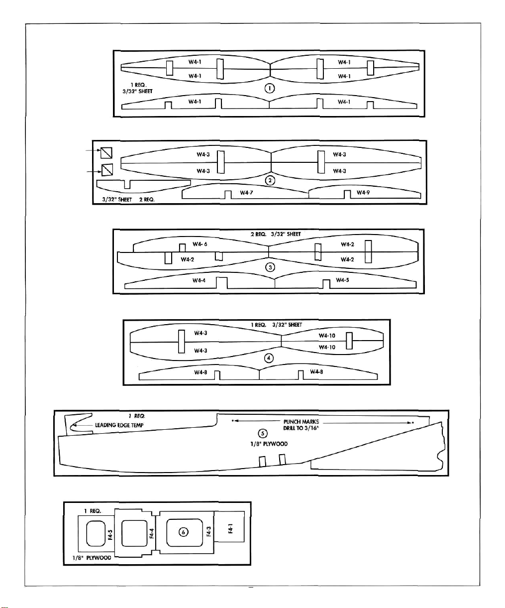
Die-Cut Layout
INNER
PANEL
GUSSETS
OUTER
PANEL
GUSSETS
NOTES ON REMOVAL OF DIE CUT PARTS FROM THE SHEET
1. Sand both sides of all die cut sheets enough to remove loose wood Fibers.
2. Bend each sheet slightly, along the direction of the grain, to identify the
side that is not cut completely through.
3. Sand this side until most of the parts can be easily removed from the sheet.
4. If a part is difficult to remove, use a sharp hobby knife to cut any
slivers of wood that are holding it in place.
7
Page 8
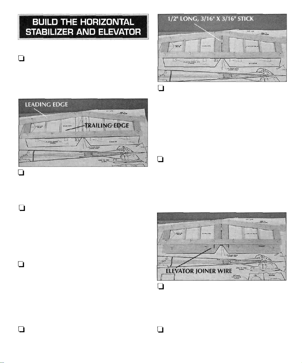
1. Unroll the plan sheet. Roll the plans inside out
to make them lie flat. Wax paper or Great Planes
Plan Protector placed over the plan will prevent
glue from sticking to the plan.
U 2. Cut an 18" long piece from the 3/16" x 15/16"
x 30" balsa stick. Pin the 18" long piece over the
horizontal stabilizer trailing edge.
Q 3. Cut a 10" long piece from the remaining
3/16" x 15/16" x 12"
over the left leading edge of the horizontal
stabilizer. Carefully mark and cut the end of the
leading edge to match the centerline of the
stabilizer. Pin the left leading edge piece in position.
balsa
stick.
Place
the
stick
LJ 6. From the remaining 3/16" x 15/16" balsa
stick, cut and fit stabilizer center sections between
the leading edges and trailing edge. Position the fin
between the two center sections for the proper
spacing. DO NOT glue the fin in position. Glue the
center sections to the leading and trailing edge.
Q 7. From a 3/16" x 3/16" x 24" balsa stick, cut/
fit and glue stabilizer ribs between the leading edge
and trailing edge. Also, cut a 1 /2" long piece and
glue it in position between the stabilizer center sections.
Ul 4. Cut another 10" long piece from the second
3/16" x 15/16" x 30"
over the right leading edge of the horizontal
stabilizer and cut the end of the right leading edge
to butt tightly against the center of the left leading
edge. Pin the right leading edge piece in position
and glue it to the left leading edge.
Q 5. From the remaining 3/16" x 15/16" x 20"
balsa stick, cut, fit and glue stabilizer tips between
the leading and trailing edges.
balsa
stick.
Place
the
stick
I—l 8. Pin the two shaped balsa elevators in position
over the plans, making sure the beveled ends are
toward the center.
Q 9. Center the pre-bent 1/16" elevator joiner
wire on the elevators and mark the location of the
"arms" on the leading edge of the elevators.
8
Page 9
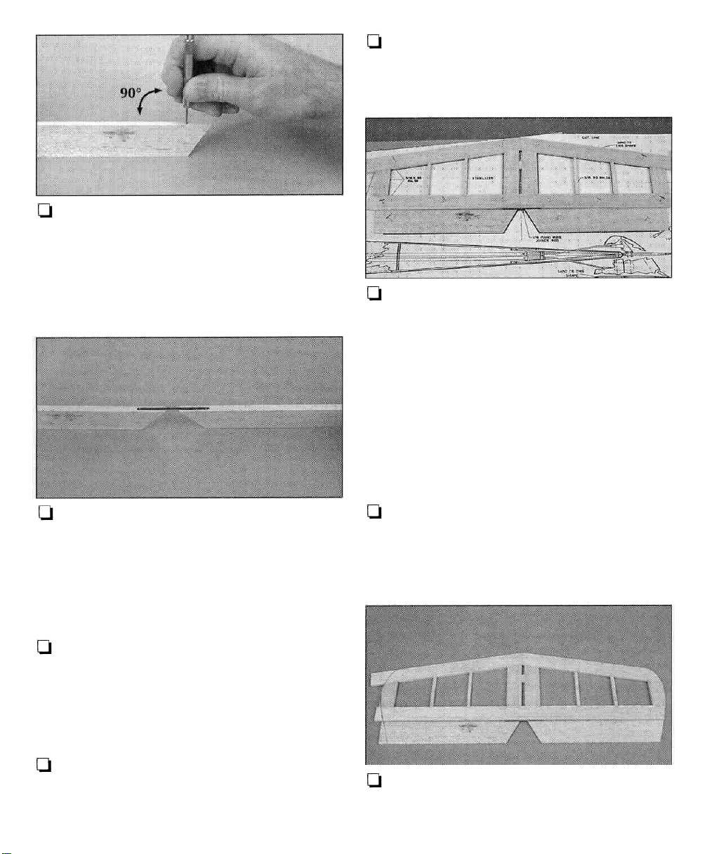
Q 10. Drill 1/16" holes, 9/16" deep, in the
leading edge of the elevators at the marked
locations. Make sure the two holes are perpendicular
to the leading edge. Be careful that the drill bit does
not break through the sides of the elevators.
Q 14. For a more secure fit, file or grind four or
five notches in each arm of the elevator joiner wire.
Thoroughly clean the joiner wire with isopropyi alcohol.
Q 15. Pack 30-minute epoxy into both elevator
joiner wire holes and in the groove on the leading
edge of the elevators. Install the joiner wire in both
elevators. Wipe off any excess epoxy with a paper
towel dampened with isopropyi alcohol. Before the
epoxy cures, place a piece of wax paper over the
joiner wire and pin the elevators flat to the building
board with the leading edge against the trailing
edge of the stabilizer.
Q 11. Cut a small groove from the hole to the
inboard end of the elevators. Gradually deepen the
groove until the joiner wire fits flush with the leading
edge of the elevators. With the elevator joiner wire
installed, the wire must be flush with the leading
edge of the elevators.
Q 12. With the joiner wire installed in the
elevators, place the assembly on a flat surface.
MAKE SURE both elevators lie flat. If they do not,
remove the joiner wire and twist it slightly. It is very
important that both elevators lie flat.
U 13. Remove the joiner wire. Mark a centerline
on the leading edge of both elevators and carefully
sand the leading edges to a "V shape as shown on
the fuselage plan.
Q 16. Remove the elevator and stabilizer from the
building board after the epoxy has cured.
1-J 17. Draw the outline for the tips on the stabilizer
and elevator using the plan as a pattern. Cut and
sand the stabilizer and elevator tips to shape.
9
Page 10

Q 18. Sand the top and bottom of the stabilizer
smooth. Sand a radius on the leading edge and tips
of the stabilizer and the tips of the elevator using the
stabilizer view as a guide.
DRILL A 3/32" HOLE
1/2" DEEP, IN CENTER
OF HINGE SLOT
1"
1"
1/2"
l-l 1. Cut the 2" x 9" hinge strip into 6 individual
(1/2" x 1") hinges and bevel the corners as shown.
Q 2. Place the stabilizer and the elevator on the
plan and mark the location of the hinges. Also,
mark the centerline on the trailing edge of the
stabilizer.
Q 4. Drill a 3/32" hole, 1/2" deep, in the center
of the hinge slot. Drilling the hole will twist some of
the wood fibers into the slot, making it difficult to
insert the hinge. Re-insert the knife blade into the
slot and work it back and forth a few times to clean
out the slot.
Q 5. Test fit the hinges into the slots and
temporarily attach the elevator to verify the fit and
operation. DO NOT glue the hinges at this time.
They will be glued in after the sailplane is covered.
CUT HINGE SLOT
WITH HOBBY KNIFE
AND #11 BLADE
Q
3. Cut the
hinge
slots
using a #11
blade.
Test
fit
the hinges into the slots. If the hinges do not slide in
easily, work the knife blade back and forth in the
slots a few times to provide more clearance.
RIGHT
WRONG
Q 6. Place a nylon control horn on the bottom of
the left elevator as shown on the plan. With the four
clevis holes aligned with the hinge line, drill a
3/32" hole through both holes in the horn base.
10
Page 11

NOTE: The control horn in the photo was painted for
clarity (The control horns in the kit are made of while
plastic).
Ul 5. Sand a radius on the leading edge of the fin
as shown on the cross section view.
Q 7. Insert two 2-56 x 1/2" machine screws
through the horn base and elevator. Place the nut
plate on top of the elevator and thread the machine
screw into the nut plate.
Ul 8. Remove the nut plate and control horn.
Reinforce the elevator by applying a couple of drops
of thin CA on the elevator where the control horn
is mounted.
Q 1. Draw a centerline completely around the edge
of the shaped balsa rudder. This will help keep the
rudder symmetrical while sanding.
Q 2. Carefully sand the shaped balsa fin and
rudder to the shape shown on the fuselage cross
section. NOTE: The weight of the fin and rudder can
be reduced by cutting lightening holes in them as
shown on the plan. This may reduce the weight
required in the nose to balance the sailplane.
Q 6. Mark and install the hinges following the
same procedure used on the stabilizer and elevator.
DO NOT glue the hinges in at this time.
Q 7. Install the control horn on the rudder following
the same procedure used with the elevator.
[.-I 1. Place wax paper or Great Planes Plan
Protector over the fuselage plan to prevent glue
from sticking to the plan.
Q 2. Put the two die-cut 3/32" balsa fuselage
sides together and check that they are the same size
and shape. If not/ lightly sand them. Compare the
fuselage sides to the fuselage plan.
Q 3. Cut a notch in the leading edge of the rudder
to clear the elevator joiner wire as shown on the plan.
Q 4. Sand a "V" on the leading edge of the rudder.
Use the cross section view as a guide.
[-1 3. Lay the fuselage sides top edge to top edge as
shown. Mark one fuselage side left and the other right.
Q 4. Lightly sand the edges of the die-cut 1/8"
plywood fuselage doublers.
11
Page 12

Qi 5. Use thick CA to glue the fuselage doublers
onto the fuselage sides, aligning the top and front
edges. Make sure to glue the doublers to the sides
with the right and left written on them.
U 6. On the left fuselage side place two marks at
the locations shown.
U 8. Pin the right fuselage side to the fuselage
plan. Use a straightedge to draw vertical lines on
the fuselage doubler and fuselage side at stations
"B" through "E". Also mark the 1/8" x 1/4" balsa
bottom cross brace, as shown on the plan.
Q 9. Remove the right fuselage side from your
building board and continue the lines around the
edges of the fuselage side.
Q 10. Hold the fuselage sides together (balsa-tobalsa) aligning the edges. Transfer the marks to the
edges of the left fuselage side. Draw vertical lines on
the fuselage doubler and balsa side, connecting the
marks. Also mark the location of the 1/8" x 1/4"
balsa bottom cross brace.
Ql 11. Cut 5-1/2" long pieces from each of the two
1/8"x1/4"x
10" balsa
sticks.
Q 7. Clamp the fuselage sides together so that the
balsa sides are against each other and the edges
align. Set the assembly on a piece of leftover
plywood with the two marks you made facing up. At
each mark, drill a 3/16" hole through the fuselage
sides. Make sure the holes are drilled perpendicular
to the fuselage sides.
Q 12. From the remaining 1/8" x 1/4" balsa
sticks, cut and glue two side braces at station "E".
NOTE: The front edges of the braces are glued
along the station line.
12
Page 13

U 13. From the remaining 3/16" square balsa
stick used on the stabilizer, cut two 1" long tail
posts. Glue a tail post to the aft end of both fuselage
sides. Glue the 5-1/2" balsa stick, cut in step 11, to
each fuselage side, flush with the stabilizer seat.
Q 14. From the 3/16" x 3/16" x 24" balsa stick,
cut two 9-3/4" long wing saddle doublers. Glue the
wing saddle doublers to the plywood fuselage doublers,
flush with the top edge of the fuselage doublers.
LJ 17. Place a leftover piece of 3/16" balsa over
the fuselage top view in front of the tail post. With
the fuselage sides inverted, align the sides with the
fuselage top view. With the tail posts aligned and
the sides of the fuselage perpendicular to the
building table, glue the tail posts together.
Q 18. Pin the fuselage sides to the building board
at former F-5. With F-5 still perpendicular to the
building board, glue it to the fuselage sides.
U 15. Using the fuselage top view as a guide,
lightly sand the tail posts to the angle shown to
allow the aft end of the fuselage sides to meet
properly.
Q 16. Pin the die-cut 1/8" plywood former F-5 in
position over the fuselage top view, perpendicular to
the building board. Make sure the longest side of
F-5 is against the building board.
I—I 19. Glue the die-cut 1/8" plywood formers F-4
and F-3 in position. Make sure the formers are
perpendicular to the building board and the
fuselage sides are aligned over the plan.
Q 20. Place the die-cut 1/8" plywood former F-1
in position. Use masking tape or clamps to hold the
fuselage sides against F-1. Check the alignment of
the fuselage sides over the plan before gluing F-1 to
the fuselage sides.
13
Page 14

Q
21.
Test
fit
the
two
1/4" x 1/2" x 2-1/4"
basswood tow hook blocks in the notches of the
plywood fuselage doubler. When you're satisfied
with the fit/ glue the blocks to the fuselage sides and
doubters with aliphatic resin or 6-minute epoxy.
After the epoxy cures/ drill a 3/32" hole in the
center of both blocks.
Q 22. Lightly sand the bottom of the fuselage so
that the plywood fuselage doublers and formers are
flush with the balsa fuselage sides.
[-] 24. From the 1/8" x 1/4" x 10" balsa stick, cut
and glue the bottom cross brace between the
fuselage sides, flush with the bottom edge. Glue the
1/4" x 3/8" x 1" balsa end cap to the tail post,
flush with the fuselage sides.
Q 25. Use thick CA to glue the 3/32" x 3" x 30"
balsa aft fuselage bottom to the edge of the 3/16"
bottom fuselage sheet, the tow hook blocks and the
fuselage sides.
Ul 26. After the glue has cured, remove the
fuselage from your building board. Starting at the
tow hook blocks, trim the aft fuselage bottom to
within 1/16" of the fuselage sides. Do not attempt
to trim the fuselage bottom from the tail post
forward. The wood may split or your knife may cut
into the fuselage sides. Save the leftover aft fuselage
bottom sheeting.
U 23. Sheet the bottom front of the fuselage with
the three 3/16" x 2-1/2" x 3" balsa bottom
forward sheets. Start at the middle of the front tow
hook block and work toward former F-1. The balsa
sheets are installed with the grain running across the
fuselage. Wetting the top of the sheets with a 50-50
mix of water and isopropyi alcohol will make the
sheets easier to mold to the fuselage contour. Use a
leftover piece of 3/16" balsa from the stabilizer to
fill the gap between the third sheet and former F-1.
Sand the sheets flush with the balsa fuselage sides.
U 27. Sand the fuselage bottom flush with the
fuselage sides.
Q 28. From the leftover 1/8" x 1/4" balsa stick,
cut and glue a top cross brace in front of the
stabilizer base, flush with the top edge of the
fuselage sides.
14
Page 15

a
21.
Test
fit the
basswood tow hook blocks in the notches of the
plywood fuselage doubler. When you're satisfied
with the fit, glue the blocks to the fuselage sides and
doublers with aliphatic resin or 6-minute epoxy.
After the epoxy cures, drill a3/32" hole in the
center of both blocks.
Q 22. Lightly sand the bottom of the fuselage so
that the plywood fuselage doublers and formers are
flush with the balsa fuselage sides.
two
1/4" x 1/2" x 2-1/4"
Q 24. From the 1/8" x 1/4" x 10" balsa stick, cut
and glue the bottom cross brace between the
fuselage sides, flush with the bottom edge. Glue the
1/4" x 3/8" x 1" balsa end cap to the tail post,
flush with the fuselage sides.
Q 25. Use thick CA to glue the 3/32" x 3" x 30"
balsa aft fuselage bottom to the edge of the 3/16"
bottom fuselage sheet, the tow hook blocks and the
fuselage sides.
Q 26. After the glue has cured, remove the
fuselage from your building board. Starting at the
tow hook blocks, trim the aft fuselage bottom to
within 1/16" of the fuselage sides. Do not attempt
to trim the fuselage bottom from the tail post
forward. The wood may split or your knife may cut
into the fuselage sides. Save the leftover aft fuselage
bottom sheeting.
Q 23. Sheet the bottom front of the fuselage with
the three 3/16" x 2-1/2" x 3" balsa bottom
forward sheets. Start at the middle of the front tow
hook block and work toward former F-1. The balsa
sheets are installed with the grain running across the
fuselage. Wetting the top of the sheets with a 50-50
mix of water and isopropyi alcohol will make the
sheets easier to mold to the fuselage contour. Use a
leftover piece of 3/16" balsa from the stabilizer to
fill the gap between the third sheet and former F-1.
Sand the sheets flush with the balsa fuselage sides.
—1 27. Sand the fuselage bottom flush with the
fuselage sides.
Q 28. From the leftover 1/8" x 1/4" balsa stick,
cut and glue a top cross brace in front of the
stabilizer base, flush with the top edge of the
fuselage sides.
14
Page 16

Q 29. Glue the 3/32" x 3" x 15" balsa aft
fuselage top from former F-4 to the front of the
stabilizer base. Trim and sand the aft fuselage top
flush with the fuselage sides.
Q 1. Trim the aft edge of the 5/8" x 2-1/2" x
5-3/4" balsa hatch block to match the radius on
the fuselage sides.
Q 4. Drill a 1/16" hole through the center of the
1/4" x 1/2" x 1-1/2" basswood hatch hold-
down block.
Q 5. Glue the hatch hold-down block to the front of
former F-3 and the underside of the sheet glued on
in step 3. After the glue has cured, insert a T-pin,
from the bottom, through the hole in the hatch holddown block and 3/32" sheet. Mark the hole
location on the sheet.
Q 6. Cut a 7/8" long hatch tab from the 1/16" x
3/8" x 1 -3/4" plywood strip. Round the corners on
the hatch tab and drill a 3/32" hole at one end at
the location shown on the plan. The remaining piece
will be used later as the hatch tongue.
Q 2. With the 1/2" x 1-7/16" x 2" balsa filler
block snug against the front of the hatch block, glue
the filler block to the fuselage. Do not glue the filler
block to the hatch block. After the glue has cured,
remove the hatch block.
U 3. From a leftover piece of 3/32" balsa sheet,
cut a 3/4" x 2-1/2" rectangle with the grain
running along the long dimension. Glue this sheet to
the top of the fuselage, with the front edge flush with
the aft edge of the hatch cut-out.
Q 7. Use a #2 x 1 /2" sheet metal screw to attach
the hatch tab to the fuselage at the mark made in
step 5. The hatch tab should be snug but still
able to rotate.
Q 8. Sand the filler block flush with the front of
former F-1.
t—1 9. If you are building the sailplane version, glue
the 2" x 2" x 2" balsa nose block to former F-1 and
the filler block. If you are building the .049 powered
version, cut out and glue the optional 1/16"
plywood firewall (not included) to former F-1 and
the filler block. The template is shown on the plan.
15
Page 17

Q 10. Make two 3/16" balsa hatch keys from
leftover 3/16" square sticks. Wedge the hatch keys
between the fuselage sides at the locations shown
on the plan. Do not glue the hatch keys to the
fuselage sides.
Q 11. With the hatch keys flush or slightly higher
than the fuselage sides, put a bead of thick CA
along the top of the hatch keys. Place the hatch in
position and hold it in place until the glue cures. Do
not glue the hatch keys to the fuselage sides.
Ql 12. Remove the hatch and glue the hatch tongue,
cut in step 6, centered on the front of the hatch.
[-1 13. After the glue has cured, test fit the hatch on
the fuselage and lock it in place with the hatch tab.
d 16. Sand the bottom of the fuselage, blending
the 3/16" bottom forward sheeting into the 3/32"
bottom aft sheeting. Use the cross sections shown on
the plan as a guide to sand a radius on the corners.
Be careful not to sand the corners too thin and
weaken the structure. Sand a radius on the 1/4"
end
cap.
LJ LJ 1. Lay the right wing plan on your building
board and cover it with Plan Protector or wax paper.
Q Q 2. Before removing the die-cut 3/32" balsa
ribs from the die sheets, label each rib using the die
patterns on page 7.
Q Q 3. Stack the W-1 through W-3 ribs together.
Insert the 1/2" x 3/8" x 24" basswood main spar in
the slot of the ribs. Lightly sand the leading and
trailing edges flush.
Q Q
4.
Test
fit
the
wing
spars in
trim the slots as necessary. Important: The slots in
the bottom of the W-1 ribs are 1/16" shallower than
the spars. This is to allow the 1/16" sheeting to fit
between the spars, flush with the top of the spars.
all
the ribs
and
U 14. Carve and sand the hatch, filler block, nose
block and 3/16" bottom sheeting to shape as
shown in the G-G cross section on the plan.
LJ 15. Cut the two pushrod exit slots at the aft end
of the fuselage. Make sure the lower slot (rudder) is
on the right side of the fuselage. The upper slot
(elevator) is on the left side of the fuselage.
U U 5. Pin the shaped 5/16" x 15/16" x
balsa trailing edge to the building board. Make
the front of the trailing edge and the tip end
aligned with the wing plan. The root end
16
24"
sure
are
will
Page 18

overhang the wing plan slightly. Also/ the 90° edge
on the trailing edge goes against the building
board. See the cross section on the left wing plan.
U U 6. Using a W-3 rib as a spacer/ pin the
shaped 5/16" x 3/8" x 24" balsa leading edge
over the plan. Note that the angled edge of the
leading edge faces up and the tip end is aligned
with rib W-4.
1-1/2"
1/8"
Q Q 7. Cut a bevel as shown on one end of the
1/4" x 1/2" x 24" basswood main spar.
Q Q 9. Pin the 1/4" x 3/8" x 10" basswood root
spar in position.
Q Q 10. Place the W-2 inboard and W-3 outboard
ribs in position to check the alignment of the main
and root spars.
Q 11. Cut two center sheets 4-1/8" long from
each of the five 1/16" x 3" x 9" balsa sheets. Set
five
of
these
sheets
aside. They
will
be
used
on the
left wing panel.
,^WJiy».
U LJ 12. Trim one of the center sheets to fit between
the leading edge and the main spar. Make sure the
spar/ leading edge and center sheet are against the
building board before gluing. Trim and glue the
second center sheet between the main spar and root
spar and the third center sheet between the root spar
and trailing edge. Save the leftover balsa sheet for
use in step 16 when sheeting the top center section.
LJ U 8. Pin the main spar over the plan with the
beveled edge down and at the tip end. Align the tip
end with the plan using a T-pin at the tip end to
prevent the main spar from moving.
U U 13. Cut the root rib dihedral template from the
plan and glue it to a piece of cardboard.
QQ14. Use the root rib gauge to set the
the W-1 root rib. Align the bottom edge of
angle of
the
rib with the centerline on the plan.
17
W-1
Page 19

Qi Q 15. Glue the two remaining W-1 ribs/ the
three W-2 ribs and the five W-3 ribs in place/
perpendicular to the building board.
Q Q 16. Glue one of the previously cut 4-1/8"
long center sheets on top of the three W-1 ribs,
butted against the leading edge. Glue the second
center sheet on top of the three W-1 ribs, butted
against the first sheet. Use a piece of leftover center
sheeting from step 12 to finish sheeting the center
section.
inboard end of the leading edge so that it butts
against the root panel leading edge. Place the W-11
rib in position and pin the leading edge in place,
but do not glue it to the root panel.
1"
1/8"
Ql t—1 3. Cut a bevel as shown on one end of the
1 /4" x 3/8" x 16" basswood tip spar.
Ql Q 4. Place the tip spar over the plan, bevel side
down. Place a pin at the inboard and outboard
ends of the spar to hold it in place. Use a clothes pin
or clamp to hold the tip spar against the main spar.
Q Q 1. Place the shaped 5/16" x 15/16" x 15"
balsa trailing edge over the wing tip plan. Trim the
inboard end of the trailing edge so that it butts
against the root panel trailing edge. Pin the trailing
edge in place but do not glue it to the root panel.
Q Q 2. Place the shaped 5/16" x 3/8" x 15"
balsa leading edge over the wing tip plan. Trim the
Q Q 5. Cut the polyhedral rib gauge template from
the plan and glue it to a piece of cardboard.
d Q 6. Use the polyhedral rib gauge to set the
angle of the W-4 root rib. Align the bottom edge of
the W-4 rib with the centerline on the plan. Glue the
rib to the tip spar and the leading and trailing edge.
Avoid gluing the rib to the main spar and the
leading and trailing edge of the root wing panel.
18
Page 20

Q Q 7. Fit the remaining W-5 through W-11 ribs
in place, perpendicular to the building board. You
may need to bevel the ends of the ribs to match the
angle of the leading and trailing edge. When you
are satisfied with the fit, glue the ribs to the tip spar
and leading and trailing edge.
U U 12. Use a razor saw and a sanding block to
trim the spars and leading and trailing edges flush
with the W-1 and W-11 ribs. Be careful to not
remove any of the rib, changing its angle.
Q Q 13. Glue the shaped 5/8" x 15/16" x 5-5/8"
balsa wing tip to rib W-11. Note the wing tip cross
section on the plan for the proper orientation.
I—I Q 14. Trim and sand the wing tip to shape. An
easy procedure to obtain the proper shape is to
cover the leading and trailing edge and ribs W-9
and W-10 with masking tape. Sand the wing tip to
the shape of rib W-11 using a sanding bar, but be
careful not to sand through the masking tape or
ribW-11.
Q Q 8. Remove the tip panel assembly from your
building board. Leave the root wing panel assembly
in place.
U U 9. Place the tip panel against the root panel
and raise the tip panel 3-3/4" at rib W-11. Notice
that the leading and trailing edges of both panels
do not fit correctly. Carefully sand the leading and
trailing edges of the wing tip panel flush with the
face of rib W-4.
LI Q 10. After checking that both panels fit
together correctly, use aliphatic resin or 30-minute
epoxy to glue the spars, leading and trailing edges
together. Make
rib W-11. Use clamps to hold the spars together
until the epoxy cures.
Q Q 11. After the epoxy cures, remove the wing
half from the building board.
sure
the
tip panel
is
raised
3-3/4"
at
Q Q 15. Locate the 1/8" plywood leading edge
template and clean-up the die-cutting around the
radius, if needed.
Q Q 16. Use the leading edge template and the
wing cross section at W-1 (shown on the fuselage
side view) as a guide while sanding the wing root
panel leading edge. The correct shape of the
leading edge is very important to the flight
characteristics of the Wanderer.
Q Q 17. Note that the tip panel ribs get smaller as
they go from W-4 to W-1 1. Carefully taper the
leading edge to match the front of the wing tip ribs.
Q Q 18. Using the leading edge template as a
general guide, sand a radius on the tip panel
leading edge.
19
Page 21

Ql Q 19. Use a sanding bar to carefully sand the
top and bottom of the wing ribs, spars, center
sheeting and leading and trailing edges flush. Do
not alter the shape of the ribs while sanding.
Q Q 20. Trim the four die-cut 3/32" x 1/2" x
1 /2" balsa gussets to fit on both sides of rib W-4 at
the leading and trailing edge. When satisfied with
the fit/ glue them in place.
Q 21. Go back to step 5 of Build The Wing Root
Pane/and build the left wing.
Q 1. Now that both wing halves are assembled,
give them a final sanding with #400-grit sandpaper.
Use a shop vacuum or compressed air to remove the
sanding dust from the wing panels.
U 2. Pin or weigh down the root panel of the left
wing. With the right wing panel elevated 3-1/4" at
rib W-4, test fit the right wing panel against the left
wing panel. If needed, lightly sand the root ribs of
the wing panels to fit.
Q 4. Handle wing with care. The center section has
little strength at this point.
U 5. Draw a line on the top and bottom of the wing
1" on each side of the center joint.
1—1 6. Read this step completely before starting. In a
well ventilated area, prop the wing up off of the
building surface. Mix approximately 5 oz. of
30-minute epoxy following the manufacturer's
instructions. Brush a thin coat of epoxy on the center
joint between the previously drawn lines. Starting at
the trailing edge, lay the 2" fiberglass cloth on the
epoxy. Use your brush to work the cloth into the
epoxy, making sure the epoxy penetrates into the
cloth. Work your way along the top of the wing,
wrapping the cloth around the leading edge and
working back toward the trailing edge on the
bottom of the wing. If the epoxy has not come
through the cloth, apply more epoxy to the area. Do
not allow the epoxy to run or puddle, as this just
adds weight, not strength. Allow the epoxy to fully
cure before moving the wing.
Q 3. When satisfied with the fit, use aliphatic resin
or 30-minute epoxy to glue the wing panels
together. Support the right wing panel at rib W-4
and pin the root ribs together. Allow the epoxy to
fully cure before removing the wing from the building
board.
U 7. After the epoxy cures, sand off any surplus
epoxy and rough edges. Trim the cloth that is
overhanging at the trailing edge flush with the
trailing edge of the wing.
20
Page 22

1—1 1. Temporarily install the two 3-3/4" wing hold
down dowels in the fuselage. Set the wing on the
fuselage and secure it by hooking a couple of
rubber bands (not included) over the forward
dowel/ stretching the rubber bands over the wing
and hooking them over the aft dowel. Set the
stabilizer in the stabilizer saddle. Check the
alignment of the stabilizer with the wing from the
front and rear of the model. If the stabilizer tips are
not equidistant above the wing/ carefully sand the
high side of the stabilizer saddle until the stabilizer
and wing are aligned. Use a tape measure to set the
stabilizer tips equal distances from the nose.
Q 2. Use T-pins to hold the stabilizer in position on
the fuselage while marking the bottom of the
stabilizer where it meets the fuselage. Do not glue it
in position at this time.
Make sure that all the surfaces to be covered have
been sanded to remove any irregularities. The
Dynaflite Wanderer can be covered with Top Flite®
MonoKote® or EconoKote® film, using the suggested
covering sequence that follows.
Suggested Covering Sequence
Fuselage and Tail:
1. Fuselage bottom
2. Fuselage right side
3. Fuselage left side
4. Fuselage top
5. Fin TE, followed by the fin sides
6. Stabilizer TE/ followed by the bottom and top
(only cover the bottom of the stabilizer up to the
marks where the fuselage meets the stabilizer)
7. Elevator LE and root ends
8. Elevator bottoms/ followed by the top
9. Rudder LE, right side followed by the left side
10. Hatch
Wing: Tack the covering to the wing tips and
leading and trailing edges. Do not shrink the
covering until after the wing is completely covered.
Do not confuse this procedure with "checking the
C.G." That will be discussed later in the manual.
Now that the model is nearly completed/ you should
balance it laterally (side-to-side). An airplane that is
laterally balanced will track better. Here's how:
U 1. Temporarily attach the stabilizer/ elevators, fin,
rudder and wing. Lift the model by the nose and the
bottom of the fuse near the rudder. This will require
an assistant. Do this several times.
Q 2. The wing that consistently drops indicates the
heavy side. Balance the model by adding weight to
the other wing tip.
1. Tips of wing
2. Trailing edges of wing
3. Bottom of both wing halves
4. Top of both wing root halves (extend the
covering 1/4" past rib W-4 and tack it to the
outboard face of the rib)
5. Top of both wing tip halves
After the wing is completely covered/ shrink the
covering on the bottom of the wing, keeping the
wing as straight as possible. Next, place the wing
root panel against a flat building surface and shrink
the covering on it.
Once the root panels are done, place a tip panel on
a flat surface. Place a 1 /4" thick shim under the aft
21
Page 23

end of the wing tip. While holding the wing leading
edge and trailing edge at rib W-4 firmly against the
flat surface, shrink the covering. This will put a slight
twist in the wing called "washout." This washout will
help prevent tip stalls when flying.
After all the covering on the wing is shrunk, iron the
covering to each wing rib.
the fit, glue the fin to the stabilizer with 30-minute
epoxy or aliphatic resin. Make sure the fin is 90° to
the stabilizer. Masking tape and T-pins can be used
to hold it in place while the epoxy cures.
5. Cut and shape the 3/32" x 1/4" x 10-3/4"
basswood nose and tail skid. Bevel the forward
face of the nose skid before gluing it on. Place the
skids in position and mark the outline of the skids on
the fuselage. Carefully remove the covering from
inside the outline. Glue the skids on the fuselage
with thick CA. The skids may be varnished or
painted after installation.
LJ 1. Center and glue the two 3-3/4" wing hold
down dowels in the fuselage.
U 2. Set the wing on the fuselage and secure it to
the fuselage by hooking a couple of rubber bands
(not included) over the forward dowel, stretching the
rubber bands over the wing and hooking them over
the aft dowel. Again, set the stabilizer in the
stabilizer saddle. Check the alignment of the
stabilizer with the wing from the front and rear of
the model. Use a tape measure to set the stabilizer
tips equal distance from the nose.
U 3. Use 30-minute epoxy to glue the stabilizer in
position on the fuselage, rechecking the alignment
before the epoxy cures.
d 6. Starting with the elevators and stab/ cut the
covering from the hinge slots.
The most common mistake made by modelers when
installing a CA type of hinge is not applying a
sufficient amount of glue to fully secure the hinge
over its entire surface area; or, the hinge slots are
very tight, restricting the flow of CA to the back of
the hinges. This results in hinges that are only "tack
glued" approximately 1/8" to 1/4" into the hinge
slots. The following technique has been developed to
help ensure thorough and secure gluing.
TEMPORARY PIN
TO KEEP HINGE
CENTERED
Q 4. Remove the covering from the bottom 3/16"
of the fin. Be very careful not to cut into the fin. Test
fit the fin in the slot at the aft end of the stabilizer.
The trailing edge of the fin should be flush with the
trailing edge of the stabilizer. When satisfied with
1 7. It is best to leave a very slight hinge gap,
rather than closing it up tight, to help prevent the
CA from wicking along the hinge line. Make sure
the control surfaces will deflect to the recommended
throws without binding. If you have cut your hinge
slots too deep, the hinges may slide in too far,
22
Page 24

leaving only a small portion of the hinge in the
control surface. To avoid this, you may insert a small
pin through the center of each hinge before
installing. This pin will keep the hinge centered while
you install the control surfaces.
Q 8. Install the hinges in the elevator and attach the
elevator to the stabilizer.
Ql 9. Apply 6 drops of thin CA adhesive to both
sides of each hinge. Allow a few seconds between
drops for the CA to wick into the slot.
Q 10. Follow the same procedure to install the
rudder on the fin.
Q 11. Reinstall the control horns.
LJ 3. Lay one of the threaded rods over the rudder
pushrod on the fuselage top view. The pin in the
clevis should be aligned with the hinge line of the
rudder and fin. Using a pliers/ make two bends in
the threaded rod at the locations shown on the plan.
Q 12. Use a T-pin inserted through the tow hook
block from the inside of the fuselage to locate the
tow hook pilot holes. Thread a 4-40 nut onto the
tow hook. Then, thread the tow hook into the tow
hook block from the bottom of the fuselage to the
depth shown on the plan.
Q
1.
Locate
pushrods. Mark one of the rods "elevator" and the
other "rudder".
Q 2. Thread a nylon clevis 20 turns onto both of
the 2-56 x 12" threaded rods.
the two
1/4"
x1/4"x
22-1/2"
balsa
LJ 4. Cut the rod 6-1/4" from the non-threaded
end. Save the piece of non-threaded rod. On the
threaded rod make a 90° bend 1 /4" from the end
of the rod, opposite the clevis.
Q 5. Use the same procedure to make the elevator
pushrod.
Q 6. Lay both pieces of balsa pushrod material
over the plan at their proper position. Mark the
pushrods at the hole location for the metal rods
(approximately 1-1/8" from the end). Drill a 3/32"
hole through the balsa pushrods at both marks (see
step 9).
LJ 7. Cut a groove in each pushrod from the hole to
the end of the pushrod. The groove needs to
wide enough for the metal rod to fit in.
LJ 8. Taper the end of both balsa pushrods
shown on the plan.
23
be
as
Page 25

Q 3. Place a spacer made from leftover 3/32"
balsa sheet between the rudder and elevator servos.
Mount the servos on the servo rails using the screws
provided with the radio system. Remove the spacer
after the servos are mounted. Wrap the receiver and
receiver battery in foam rubber and place them in
front of the servos.
LJ 9. Install the metal rods in each balsa pushrod.
Wrap the ends of the pushrods with heavy-duty
button thread and apply epoxy to hold the thread in
position and add strength. Set the pushrods aside to
allow the epoxy to cure.
Q 1. Place a couple of pieces of leftover 1/16"
balsa sheeting in the bottom of the radio
compartment to raise the servos. Install the rubber
grommets and eyelets on the rudder and elevator
servos. Set the servos in the radio compartment. Test
fit the aft 1/4" x 1/2" x 2" basswood servo rail in
position. The rail should be snug against the
fuselage sides, but not so tight that it causes the
fuselage sides to bow outward. Once you're
satisfied with the fit, use 6-minute epoxy or aliphatic
resin to glue the aft servo rail in place.
Q 2. After the epoxy cures/ test fit the forward
1/4" x 1/2" x 2" basswood servo rail in position
and glue it in place.
CUT
STRAIN RELIEF
INSIDE FUSELAGE
CUT
RUBBER
BAND
Q 4. Drill a small hole in the side of the fuselage
next to the receiver. Route the receiver antenna out
the hole and attach it to the vertical stabilizer with a
rubber band and T-pin.
Q 5. Install the receiver switch in the side of the
fuselage and connect it to the receiver and receiver
battery.
U 6. Drill a 3/32" hole 1-1/8" from the end of
both balsa pushrods. The holes should be on the
same sides as the holes used for the threaded rod.
Cut a groove from each hole to the end of the
pushrod. The groove needs to be wide enough for
the leftover metal rod to fit in.
24
T-PIN
Page 26

Q 7. Make a 90° bend 1 /4" from the end of both
leftover metal rods. Insert the metal rods in the
grooves of the balsa pushrods and use thread and
epoxy to secure them using the same procedure
as before.
Q 8. Remove the clevises from the pushrods and
insert them in the fuselage. Make sure the correct
pushrod exits the correct slot at the aft end of the
fuselage.
Q 9. Reinstall the clevises to the pushrods and
connect them to the control horns.
Q 10. Install a servo wheel on each servo. Switch
on the transmitter and receiver and center the trims
on your transmitter. Switch the radio system off.
Q 12. Remove the clevises from the pushrods and
the pushrods from the fuselage. Bend the pushrods
down at a 90° angle. Make a second 90° bend
approximately 3/16" from the first bend and trim the
excess rod 1 /8" from the second bend.
LJ 11. With the rudder and elevator in the neutral
position, mark the elevator pushrod where it crosses
the servo wheel at the 3 o'clock position. Mark the
rudder pushrod where it crosses the rudder servo
wheel at the 9 o'clock position.
Q 13. Remove the servo wheels from the servos.
Use a 5/64" drill to enlarge the hole in the servo
wheel for the pushrod. Insert the pushrods in the
servo wheels and reinstall the servo wheels on
the servos.
Ul 14. Install the hatch and switch the radio system
on. Move the controls on the transmitter to check for
any binding of the pushrods.
25
Page 27

We recommend the following control surface throws:
4-CHANNEL RADIO SET-UP
(STANDARD MODE 2)
ELEVATOR MOVES UP
RUDDER MOVES RIGHT
2-CHANNEL RADIO SET-UP
ELEVATOR MOVES UP
Elevator: 3/8" [9.5mm] up
Rudder: 1-1/2" [38mm] left
Note: The balance and control throws for the
Wanderer have been extensively tested. This chart
indicates the settings at which the Wanderer flies
best. Please set up your model to the specifications
listed above. If, after you become comfortable with
your Wanderer, you would like to adjust the throws
to suit your tastes, that's fine. Too much throw can
force the sailplane into a stall, so remember, "more
is not always better."
NOTE: This section is VERY important and must NOT
be omitted! A model that is not properly balanced
will be unstable and possibly unflyable.
3/8"[9.5mm] down
1-1/2"[38mm] right
RUDDER MOVES RIGHT
The throws are measured at the widest part of the
elevator and rudder. Adjust the position of the
pushrods at the servo wheels to control the amount
of throw. You may also use the ATV's if your
transmitter has them but the mechanical linkages
should still be set so the ATV's are near 100% for
the best servo resolution (smoothest, most
proportional movement).
2-11/16"
[68 mm]
Q 1. The balance point (C.G.) is located 2-11/16"
[68 mm] back from the leading edge of the wing,
next to the fuse sides as shown in the sketch and on
the fuselage plan. Accurately mark the balance
point on the bottom of the wing on both sides of the
fuselage. Use thin strips of tape or a felt-tip pen to
make the marks.
26
Page 28

Hint: Reference the full-size fuse plan to help you
locate the proper balance point. This is the balance
point at which your model should balance for your
first flights. After initial trim flights and when you
become more acquainted with your Wanderer, you
may wish to experiment by shifting the balance up
to 3/16"
its flying characteristics. Moving the balance
forward may improve the smoothness and stability,
but the model may become more difficult to slow for
landing. Moving the balance aft makes the model
more agile with a lighter, snappier "feel." In any
case, please start at the location we recommend. Do
not at any time balance your model outside the
recommended C.G. range.
[5
mm] forward or backward to change
3. Set the model on the balancer at the balance
point. If the tail drops, the model is "tail heavy" and
you must add weight to the nose to balance the
model. If the nose drops, it is "nose heavy" and you
must add weight to the tail to balance the model.
NOTE: Weight may be added by using Great Planes
(GPMQ4485) "stick-on" lead weights. Later, if the
balance is O.K., you can glue the weights inside the
fuselage permanently.
If possible, first attempt to balance the model by
changing the position of the receiver battery. If you
are unable to obtain good balance by doing so,
then it will be necessary to add weight to the nose
or tail to achieve the proper balance point.
At this time check all connections, including servo
horn screws, clevises and servo cords.
Q 2. Attach the wing to the fuselage with six #64
rubber bands, two on each side running straight
across the wing and two crossing the wing to form
an "X". With the wing attached to the fuselage and
all parts of the model installed (ready to fly), hold
the model right side up with the stabilizer level. The
Great Planes CG Machine™ Balancer works great
for balancing the model.
CHARGE THE BATTERIES
Follow the battery charging procedures in your
radio instruction manual. You should always charge
your transmitter and receiver batteries the night
before you go flying and at other times as
recommended by the radio manufacturer.
GROUND CHECK YOUR
MODEL
Inspect your radio installation and confirm that all
the control surfaces respond correctly to the
transmitter inputs. Make sure all screws remain tight
and the hinges are secure.
27
Page 29

RANGE CHECK YOUR MODEL
LANDING
Whenever you go to the flying field, check the
operational range of the radio before the first flight
of the day. First, make sure no one else is on your
frequency (channel). With your transmitter on and
the antenna collapsed you should be able to walk at
least 100 feet away from the model and still have
control. While you work the controls, have a helper
stand by your model and tell you what the control
surfaces are doing. If the control surfaces are not
always responding correctly, do not fly! Find and
correct the problem first. Look for loose servo
connections or corrosion, a defective on/off switch,
low battery voltage or a defective receiver battery, a
damaged receiver antenna, or a receiver crystal that
may have been damaged from a previous crash.
When it's time to land, fly a normal rectangular
landing pattern with your final approach directly
into the wind. For your first few landings/ plan to
land slightly faster than stall speed.
Have a ball! But always remember to think about
your next move and plan each maneuver before you
do it. Impulsively "jamming the sticks" without any
thought is what gets most fliers in trouble, not lack of
flying skill. Happy Landings!
DYNAFLITE™ HI-STARTS
DYFP8301 (Standard) .
DYFP8302 (Heavy-Duty)
We recommend that if you have never previously
flown an R/C airplane, you find an experienced
sailplane pilot. An experienced pilot will be able to
help you get the Wanderer trimmed properly and to
help you with your first few flights. If you cannot
locate an experienced pilot, we recommend that you
gently hand launch the Wanderer a few times to get
the sailplane trimmed out for a smooth glide. Get
the feel of the controls. Try to avoid using the rudder.
At this low of an altitude the wing tips may catch the
ground and damage the Wanderer. After you are
comfortable with the controls, you can then move up
to a
hi-start launch.
We recommend that you take it easy with your
Wanderer for the first several flights, gradually
"getting acquainted" with this great model.
• Compact power for high-altitude launches.
• Complete systems for 2-meter and unlimited class
sailplanes.
A Dynaflite Hi-Start and 800' of clear launch
all you need to send your sailplane rocketing up to 500'
in the air! Easy to lay out and retrieve, Hi-Starts include
everything required for sailplane launches: 100' of UVstabilized surgical tubing, injection-molded reel,
parachute, steel stake and tow ring, and nylon tow line.
Standard Hi-Start with 1/8" diameter tubing offers
strong, steady power for 2-meter sailplanes. Heavy-Duty
Hi-Start with 3/16" diameter tubing provides the launch
power needed for sailplanes spanning 100" or more.
area are
 Loading...