

Page 1
SE5AP03 for DYFA3045 Printed in USA V1.1
READ THROUGH THIS MANUAL BEFORE STARTING CONSTRUCTION. IT
CONTAINS IMPORTANT INSTRUCTIONS AND WARNINGS CONCERNING THE
ASSEMBLY AND USE OF THIS MODEL.
Entire Contents © Copyright 2007
Instruction Manual
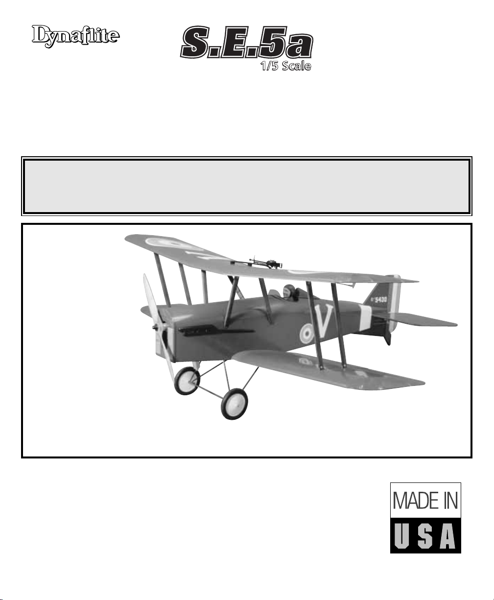
• QUICK BUILDING – IDEAL FOR FUN-SCALE COMPETITION
• 64" WINGSPAN (IMAA Legal)
• SMOOTH-FLYING BIPE – CAPABLE OF SCALE AEROBATICS
WARRANTY
Dynaflite
™
guarantees this kit to be free from defects in both material and workmanship at the
date of purchase. This warranty does not cover any component parts damaged by use or
modification. In no case shall Dynaflite’s liability exceed the original cost of the
purchased kit. Further, Dynaflite reserves the right to change or modify this warranty without
notice. In that Dynaflite has no control over the final assembly or material used for final
assembly, no liability shall be assumed nor accepted for any damage resulting from the use by
the user of the final user-assembled product. By the act of using the user-assembled product,
the user accepts all resulting liability. If the buyer is not prepared to accept the liability
associated with the use of this product, the buyer is advised to return this kit
immediately in new and unused condition to the place of purchase.
™
Wingspan: 64 in [1625mm]
Wing Area: 1440 sq in [93dm
2
]
Weight: 12.0 - 13.5 lb [5440 - 6120g]
Wing Loading: 19.2 - 21.3 oz/sq ft [59 - 65g/dm
2
]
Fuselage Length: 53 in [1345mm]
Engine: .61 - 1.20 cu in [10.0 - 19.5cc] two-stroke, .91 - 1.20 cu in
[15.0 - 19.5cc] four-stroke
Radio: 4-channel, 7 or 8 servos (single or dual elevator servos)
Page 2
INTRODUCTION ..............................................2
IMAA ..........................................................................3
Scale Competition ....................................................3
SAFETY PRECAUTIONS ..................................3
DECISIONS YOU MUST MAKE ........................4
Radio Equipment ......................................................4
Engine Recommendations ......................................5
Covering & Paint ......................................................5
ADDITIONAL ITEMS REQUIRED......................5
Hardware & Accessories ..........................................5
Adhesives & Building Supplies ..............................6
Covering Tools ..........................................................6
Optional Supplies & Tools ........................................6
Important Building Notes ........................................7
Metric Conversions ..................................................8
Metric/Inch Ruler ......................................................8
DIE DRAWINGS ......................................9 & 10
LABEL THE PARTS ........................................11
BUILD THE TAIL SURFACES ..........................11
BUILD THE WING ..........................................13
Build the Bottom Center Panel ..............................13
Build the Top Center Panel......................................16
Build the Outer Panels ............................................17
Mount the Aileron Servos ......................................20
Build the Wing Tips..................................................21
Join the Wing Panels ..............................................24
BUILD THE FUSELAGE ..................................25
Build the Fuselage Sides ........................................25
Mount the Fuel Tank................................................29
Install the Strut Mounts ..........................................29
Mount the Engine....................................................31
Build the Top of the Fuselage ................................33
FINAL CONSTRUCTION ................................35
Mount the Bottom Wing ........................................35
Fit the Stab & Fin ....................................................37
Make the Tail Gear Mount ......................................39
Mount the Main Landing Gear ..............................40
Prepare the Wing Struts..........................................41
Mount the Engine Cowls ........................................42
Cover the Model ......................................................43
Painting ....................................................................45
FINAL ASSEMBLY ........................................46
Glue in the Stab & Fin ............................................46
Hinge the Control Surfaces ....................................48
Finish the Wing Struts ............................................48
Finish the Radio Installation ..................................51
Finish the Cockpit ....................................................53
Machine Gun............................................................54
Apply the Decals ....................................................55
GET THE MODEL READY TO FLY ..................55
Check the Control Directions..................................55
Set the Control Throws ..........................................55
Balance the Model (C.G.)........................................56
Balance the Model Laterally ..................................57
PREFLIGHT....................................................57
Identify Your Model ................................................57
Charge the Batteries................................................57
Balance the Propeller ..............................................58
Ground Check ..........................................................58
Range Check ............................................................58
ENGINE SAFETY PRECAUTIONS ..................58
AMA SAFETY CODE (excerpt) ......................59
IMAA SAFETY CODE (excerpt) ....................60
CHECK LIST ..................................................60
FLYING ..........................................................61
Fuel Mixture Adjustments ......................................61
Field Assembly ........................................................62
Takeoff ......................................................................62
Flight ........................................................................62
Landing ....................................................................63
Thank you for purchasing the Dynaflite S.E.5a.
This kit is intended for modelers who desire the
nostalgic appearance and gentle flight
characteristics of a WWI biplane, but don’t wish
to spend hours in the shop working on minute
scale details. Simply by following the
instructions
you’ll end up with a model that very much
represents an S.E.5a featuring the most
important characteristics including exhaust
pipes, wing struts, pilot head rest, wooden tail
gear and simulated radiators. Of course, if you
like to fiddle and spend extra time there’s no
end to the amount of detail you could add on
your own.
For the latest technical updates or manual
corrections to this model visit the web site
listed below and select the Dynaflite S.E.5a. If
there is new technical information or changes to
this kit a “tech notice” box will appear in the
upper left corner of the page.
http://www.dynaflite.com
INTRODUCTION
TABLE OF CONTENTS
2
Page 3

The Dynaflite S.E.5a is an excellent sport-scale
model. Because it’s a biplane with a wingspan
over 60", it is eligible to fly in IMAA events. The
IMAA (International Miniature Aircraft
Association) is an organization that promotes
non-competitive flying of giant-scale models. If
you plan to attend an IMAA event, contact the
IMAA for a copy of the IMAA Safety Code at
the address or telephone number below.
IMAA
205 S. Hilldale Road
Salina, KS 67401
(913) 823-5569
Though the Dynaflite S.E.5a may not have the
same level of detail as an “all-out” scratch-built
competition model, it is a scale model
nonetheless and is therefore eligible to
compete in the
Fun Scale
class in AMA
competition. This is the perfect place for
beginning scale modelers to “get their feet
wet.” To receive the five points
for scale
documentation, the only proof
required that a
full size aircraft of this type in your
paint/markings scheme did exist is a single
sheet such as a kit box cover from a plastic
model, a photo, or a profile painting, etc. If the
photo is in black and white other written
documentation of color must be provided.
Contact the AMA for a rule book with full
details.
Note: The full-size S.E.5a has a wingspan of
26'-4" [slightly over 8m]. This model has a
wingspan of 64" [1625mm], so the scale is
20.25%, or slightly larger than 1/5 scale. The
model featured on the kit box cover and in this
instruction manual was finished similar to
the
one on the cover of the Squadron
Publication’s
S.E.5a in Action
book (No. 1069).
This book
contains many photographs,
different trim
schemes and documentation that would be
useful for finishing your model and getting to
know more about the full-size S.E.5a.
Another source of photographs, three-view
drawings and scale documentation is:
Bob’s Aircraft Documentation
3114 Yukon Ave
Costa Mesa, CA 92626
Telephone: (714) 979-8058
Fax: (714) 979-7279
e-mail:
www.bobsairdoc.com
1. Your S.E.5a should not be considered a toy,
but rather a sophisticated, working model that
functions very much like a full-size airplane.
Because of its performance capabilities, the
S.E.5a, if not assembled and operated correctly,
could possibly cause injury to yourself or
spectators and damage to property.
2. You must assemble the model according to
the instructions. Do not alter or modify the
model, as doing so may result in an unsafe or
unflyable model. In a few cases the instructions
may differ slightly from the photos. In those
instances the written instructions should be
considered as correct.
3. You must take time to build straight, true
and strong.
4. You must use an R/C radio system that is in
first-class condition, and a correctly sized
engine and components (fuel tank, wheels, etc.)
throughout the building process.
PROTECT YOUR MODEL,
YOURSELF & OTHERS...
FOLLOW THESE IMPORTANT
SAFETY PRECAUTIONS
SCALE COMPETITION
IMAA
3
Page 4
5. You must correctly install all R/C and other
components so that the model operates
correctly on the ground and in the air.
6. You must check the operation of the model
before every flight to insure that all equipment
is operating and that the model has remained
structurally sound. Be sure to check clevises or
other connectors often and replace them if they
show any signs of wear or fatigue.
7. If you are not already an experienced R/C
pilot, you should fly the model only with the
help of a competent, experienced R/C pilot.
8. While this kit has been flight tested to exceed
normal use, if the plane will be used for
extremely high stress flying, such as aggressive
aerobatics, the modeler is responsible for
taking steps to reinforce the high stress points.
Remember: Take your time and follow the
instructions to end up with a well-built
model that is straight and true.
Before starting to build, compare the
parts in this kit with the Parts List, and
note any missing parts. Also inspect all
parts to make sure they are of acceptable
quality. If any parts are missing, broken or
defective, or if you have any questions
about building or flying this airplane,
please call us at (217) 398-8970, or e-mail
us at productsupport@greatplanes.com. If
you are contacting us for replacement
parts, please be sure to provide the full kit
name (Dynaflite S.E.5a) and the part
numbers as listed in the Parts List.
You can also check our web site at
www.dynaflite.com for the latest S.E.5a
updates.
If you have not flown this type of model before,
we recommend that you get the assistance of
an experienced pilot in your R/C club for your
first flights. If you’re not a member of a club,
your local hobby shop has information about
clubs in your area whose membership includes
experienced pilots.
In addition to joining an R/C club, we strongly
recommend you join the AMA (Academy of
Model Aeronautics). AMA membership is
required to fly at AMA sanctioned clubs. There
are over 2,500 AMA chartered clubs across the
country. Among other benefits, the AMA
provides insurance to its members who fly at
sanctioned sites and events. Additionally,
training programs and instructors are available
at AMA club sites to help you get started the
right way. Contact the AMA at the address or
toll-free phone number below:
The Dynaflite S.E.5a may be operated with
either seven or eight servos. The elevators are
connected to separate pushrods, but the
pushrods may be linked together and
connected
RADIO EQUIPMENT
DECISIONS YOU MUST
MAKE
Academy of Model
Aeronautics
5151 East Memorial Drive
Muncie, IN 47302
Tele: (800) 435-9262
Fax (765) 741-0057
Or via the Internet at:
http://www.modelaircraft.org
We, as the kit manufacturer, provide you with
a top quality kit and instructions, but
ultimately the quality and flyability of your
finished model depends on how you build it;
therefore, we cannot in any way guarantee
the performance of your completed model,
and no representations are expressed or
implied as to the performance or safety of
your completed model.
4
Page 5
to one servo, or connected to separate servos. If
powering the S.E.5a with an engine in the
upper end of the recommended range, and/or if
you plan of flying lots of aerobatics with your
S.E.5a, two elevator servos are recommended.
If two servos are used for the elevators, a radio
capable of electronic mixing (so one of the
servos can be “reversed”) must be used, or an
electronic device to make one of the servos
move in the opposite direction will be required.
The Futaba®SR-10 Synchronized Servo
Reverser
(FUTM4150) may be used to reverse one of the
servos and is compatible with most popular
radio systems.
As for the type of servos, servos with a
minimum of 50 oz.-in. of torque are
recommended for the elevator(s) and rudder,
while standard servos may be used on the
ailerons and throttle.
Three (3) Hobbico
®
Pro Series™“Y” Harnesses
(HCAM2751 for Futaba J connectors) are also
required for the ailerons (one “Y” Harness in
each wing and one inside the fuselage).
A receiver battery with a minimum capacity of
1,000 mAh is also recommended.
Keep in mind that this is a scale model of a WWI
biplane that is intended to fly in a scale-like
manner-planes of that day weren’t capable of
some of the high-stress aerobatic maneuvers
flown today. The Dynaflite S.E.5a flies most
scale-like with engines nearer the bottom of the
recommended size range. Even with the O.S.
®
MAX .91 four-stroke, the model was flown at
reduced throttle settings much of the time. If the
S.E.5a is powered by an engine in the upper
end of the recommended size range prudent
throttle management must be used.
The S.E.5a on the kit box cover was covered
primarily with flat olive drab and flat cream Top
Flite®MonoKote®film. The white band around
the fuselage was made from white MonoKote
and the rudder was covered with dark red, sky
blue and white MonoKote (scuffed with 600-grit
sandpaper to remove the shine). The plastic
parts (cowl, headrest, etc.) were painted with
olive drab Top Flite LustreKote®(TOPR7210). The
wing struts and tail gear mount were stained
with Minwax Special Walnut 224 stain, then
clear-coated with crystal clear LustreKote
(TOPR7200). Below are the order numbers for
full 6' rolls of covering to finish the model like
the one on the kit box cover (only
approximately one foot of dark red, white and
sky blue are required).
Flat Olive Drab (two rolls) – TOPQ0510
Flat Cream (one roll) – TOPQ0512
White – TOPQ0204
Sky Blue – TOPQ0206
Dark Red – TOPQ0218
This is the list of hardware and accessories
used to finish the S.E.5a. Order numbers are
provided in parentheses.
❏
(3) Y-harnesses for ailerons (HCAM2751 for
Futaba)
❏
R/C foam rubber (1/4" [6mm] - HCAQ1000,
or 1/2" [13mm] - HCAQ1050)
❏
10 oz. [300cc] fuel tank (GPMQ4104)
❏
Propeller and spare propellers
❏
3' [900mm] standard silicone fuel tubing
(GPMQ4131)
❏
Fuel filler valve for glow fuel (GPMQ4160)
HARDWARE & ACCESSORIES
ADDITIONAL ITEMS
REQUIRED
COVERING & PAINT
ENGINE RECOMMENDATIONS
5
Page 6
❏
William’s Brothers #13300 5" [127mm]
Vintage Wheels (WBRQ1133)
❏
1/2" [13mm] double-sided foam mounting
tape (GPMQ4440)
❏
Velcro hook and loop material (for
mounting battery pack, GPMQ4480)
❏
Great Planes long-handle 3/32" hex driver
ball wrench (for wing strut screws,
GPMR8002)
❏
2 oz. [60g] Thin Pro CA (GPMR6003)
❏
2 oz. [60g] Medium Pro CA+ (GPMR6009)
❏
Pro™30-minute epoxy (GPMR6047)
❏
Milled fiberglass (GPMR6165) -or-
❏
Microballoons (TOPR1090)
❏
HobbyLite™balsa-colored balsa filler
(HCAR3401)
❏
Plan protector (GPMR6167) or wax paper
❏
Threadlocker thread locking cement
(GPMR6060)
❏
Drill bits: 1/16" [1.6mm], 3/32" [2.4mm],
1/8" [3.2mm], 9/64" [3.6mm] (or 1/8"
[3.2mm]), 5/32" [4mm], 3/16" [4.8mm],
13/64" [5.2mm], 1/4" [6.4mm], 17/64"
[6.7mm] (or 1/4" [6.4mm]), #34 (or 17/64"
[6.7mm])
❏
6-32 tap and #36 (or 17/64" 6.7mm]) drill or
Great Planes 6-32 tap and drill set
(GPMR8102)
❏
1/4-20 tap and #7 (or 13/64" [5.2mm]) drill
or Great Planes 1/4-20 tap and drill set
(GPMR8105)
❏
Tap handle (GPMR8120)
❏
Silver solder w/flux (GPMR8070)
❏
Stick-on segmented lead weights
(GPMQ4485)
❏
#1 Hobby knife (HCAR0105)
❏
#11 blades (5-pack, HCAR0211)
❏
#11 blades (100-pack, HCAR0311)
❏
T-pins (small – HCAR5100, medium –
HCAR5150, large – large HCAR5200)
❏
3/16" [4.8mm] K&S brass tube
❏
X-Acto®#240 razor saw (XACR1440)
❏
Sanding tools and sandpaper assortment
(see
“Easy-Touch™Bar Sander”
section)
❏
21st Century®sealing iron (COVR2700)
❏
21st Century iron cover (COVR2702)
❏
21st Century trim seal iron (COVR2750)
Here is a list of optional tools and accessories
mentioned in the manual that will help you
build the S.E.5a.
❏
16" x 36" [410 x 910mm] building board
(GPMR6948)
❏
Robart Super Stand II (ROBP1402)
❏
William’s Brother’s #625 1/4-scale
standard pilot (WBRQ2625)
❏
Acrylic paint and paint brushes for
painting pilot (found at hobby and craft
stores)
❏
William’s Brother’s #161 2" 1/6-scale Lewis
Aircraft machine gun (WBRQ3561)
❏
Fourmost Products #FOR 114 regular
cockpit coaming (FORQ2014)
❏
Masking tape (TOPR8018)
❏
CA activator (2 oz. [57g] spray –
GPMR6035, or 4 oz. [113g] aerosol –
GPMR634)
❏
CA applicator tips (HCAR3780)
❏
CA debonder (GPMR6039)
❏
Denatured alcohol (for epoxy clean up)
❏
Epoxy brushes (6, GPMR8060)
❏
Mixing sticks (50, GPMR8055)
❏
Mixing cups (GPMR8056)
❏
Slot Machine™hinge slotting tool (110V,
GPMR4010)
❏
Builder’s Triangle Set (HCAR0480)
❏
Curved-tip canopy scissors for trimming
plastic parts (HCAR0667)
OPTIONAL SUPPLIES
& TOOLS
COVERING TOOLS
ADHESIVES & BUILDING
SUPPLIES
6
Page 7
❏
D.G. Products Perma-Grit tungsten
carbide flat sanding bar
❏
Heat shrink tubing (for securing servo wire
connections inside wings, GPMM1058)
❏
K & S #801 Kevlar thread (for stab
alignment, K+SR4575)
❏
Switch & Charge Jack Mounting Set
(GPMM1000)
❏ Remote glow plug hookup (Sullivan #M
021
Remote Headlock, MODP1221
❏
Panel Line Pen (TOPQ2510)
❏
Rotary tool such as Dremel®Moto-Tool
®
❏
Rotary tool reinforced cut-off wheel
(GPMR8020)
❏
Servo horn drill (HCAR0698)
❏
Hobby Heat™micro torch (HCAR0750)
❏
Dead Center™engine mount hole locator
(GPMR8130)
❏ AccuThrow
™
deflection gauge
(GPMR2405)
❏
Laser incidence meter (GPMR4020)
❏
Precision Magnetic Prop Balancer
™
(TOPQ5700)
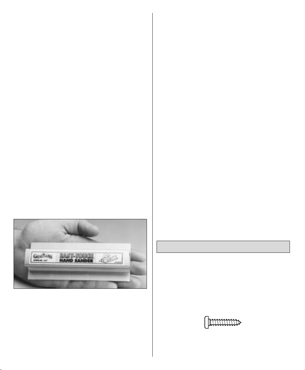
A flat, durable, easy to handle sanding tool is a
necessity for building a well-finished model.
Great Planes makes a complete range of EasyTouch Bar Sanders and replaceable Easy-Touch
Adhesive-backed Sandpaper. While building the
S.E.5a, two 5-1/2" [140mm] Bar Sanders and
two 11" [280mm] Bar Sanders equipped with
80-grit and 150-grit Adhesive-backed
Sandpaper were used.
Here’s the complete list of Easy-Touch Bar
Sanders and Adhesive Backed Sandpaper:
5-1/2" [140mm] Bar Sander (GPMR6169)
11" [280mm] Bar Sander (GPMR6170)
22" [560mm] Bar Sander (GPMR6172)
33" [840mm] Bar Sander (GPMR6174)
44" [1120mm] Bar Sander (GPMR6176)
11" [280mm] Contour Multi-Sander
(GPMR6190)
12' [3.66m] rolls of Adhesive-backed sandpaper:
80-grit (GPMR6180)
150-grit (GPMR6183)
180-grit (GPMR6184)
220-grit (GPMR6185)
Assortment pack of 5-1/2" [140mm] strips
(GPMR6189)
We also use Top Flite 320-grit (TOPR8030, 4
sheets) and 400-grit (TOPR8032, 4 sheets) wetor-dry sandpaper for finish sanding.
• There are two types of screws used in this
kit:
Sheet metal screws are designated by a
number and a length.
For example #6 x 3/4"
This is a number six screw that is 3/4" long.
IMPORTANT BUILDING
NOTES
7
Page 8
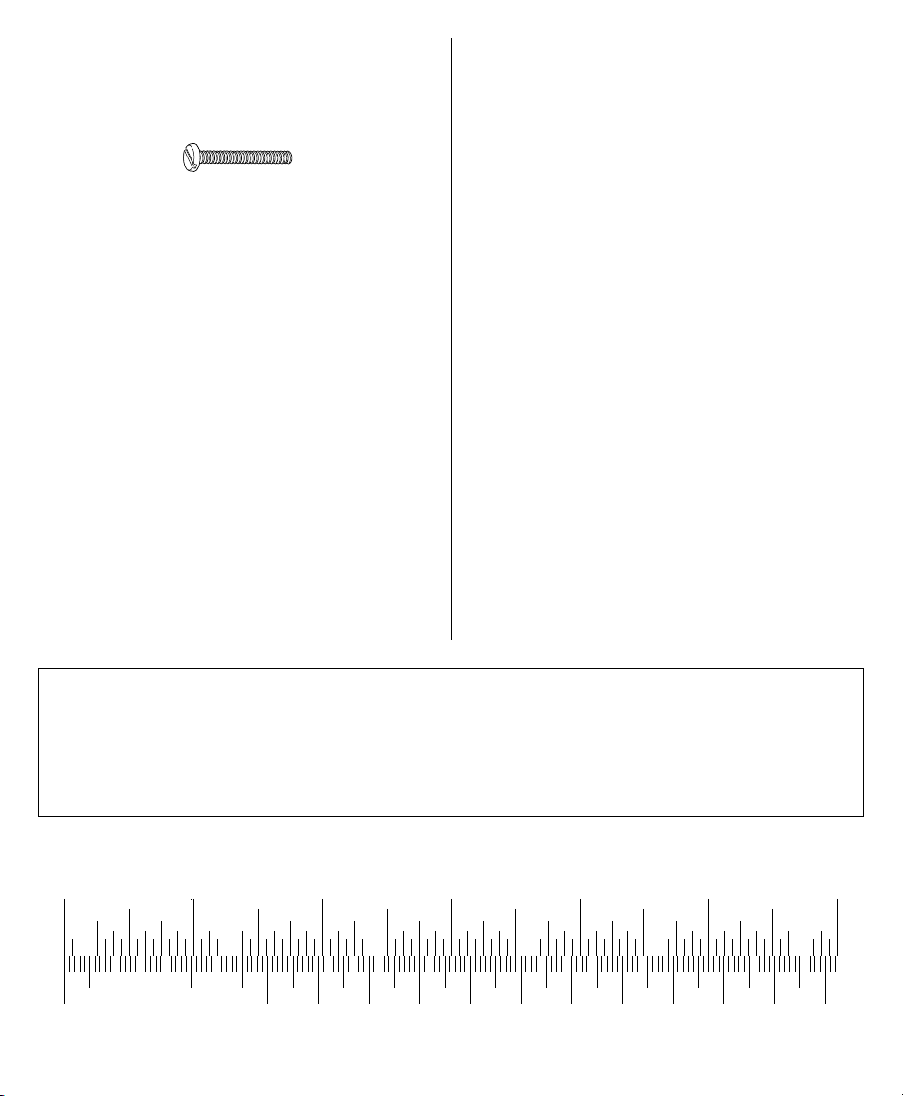
Machine screws are designated by a number,
threads per inch, and a length.
For example 4-40 x 3/4"
This is a number four screw that is 3/4" long
with forty threads per inch.
• When you see the term
test fit
in the
instructions, it means that you should first
position the part on the assembly without
using any glue, then slightly modify or
custom
fit
the part as necessary for the best fit.
• Whenever the term
glue
is written you
should rely upon your experience to decide
what type of glue to use. When a specific type
of adhesive works best for that step, the
instructions will make a recommendation.
• Whenever just
epoxy
is specified you may
use
either
30-minute (or 45-minute) epoxy
or
6-minute epoxy. When 30-minute epoxy is
specified it is highly recommended that you
use only 30-minute (or 45-minute) epoxy,
because you will need the working time and/or
the additional strength.
• Photos and sketches are placed before
the step they refer to. Frequently you can study
photos in following steps to get another view of
the same parts.
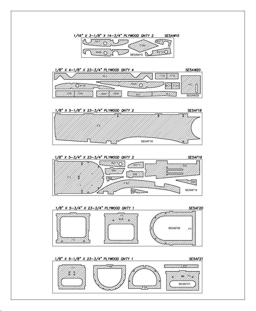
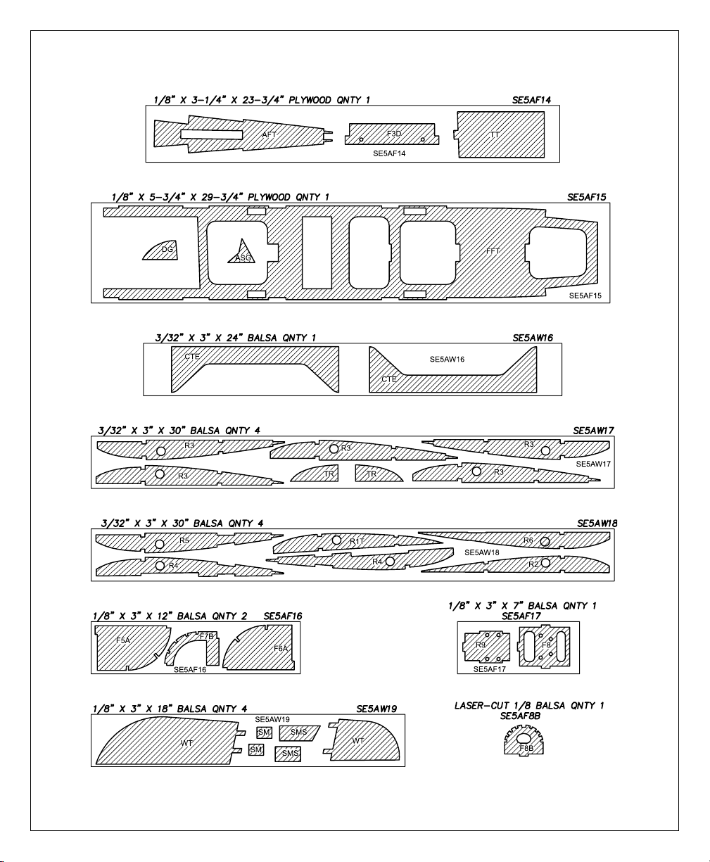
• Not all die-cut parts have a name, or their
complete name stamped on them, so refer to
the die drawings on pages 9 and 10 for
identification. When it's time to remove the
parts from their die sheets, if they are difficult to
remove, do not force them out. Instead, use a
sharp #11 blade to carefully cut the part from
the sheet, then lightly sand the edges to remove
any slivers or irregularities. Save some of the
larger scraps of wood.
• The easiest way to cut balsa sticks is with a
single-edge razor blade or razor saw. Position
the stick over the plan, mark its size, then cut
the part on a piece of scrap wood. A modeling
miter box works well for cutting square corners
and 45° gussets.
8
METRIC CONVERSIONS
1/64" = .4 mm
1/32" = .8 mm
1/16" = 1.6 mm
3/32" = 2.4 mm
1/8" = 3.2 mm
5/32" = 4.0 mm
3/16" = 4.8 mm
1/4" = 6.4 mm
3/8" = 9.5 mm
1/2" = 12.7 mm
5/8" = 15.9 mm
3/4" = 19.0 mm
1" = 25.4 mm
2" = 50.8 mm
3" = 76.2 mm
6" = 152.4 mm
12" = 304.8 mm
18" = 457.2 mm
21" = 533.4 mm
24" = 609.6 mm
30" = 762.0 mm
36" = 914.4 mm
Inch Scale
0" 1" 2" 3" 4" 5" 6"
0 10 20 30 40 50 60 70 80 90 100 110 120 130 140 150
Metric Scale
Page 9
9
Die Drawing
Page 10
10
Die Drawing
Page 11
❏
Use the
die drawings
on pages 9 and 10 to
identify and mark the die-cut parts with a
ballpoint pen before removing them from their
die sheets (some, but not all of the parts already
have numbers or names stamped on them).
While building, if a part is difficult to remove
from its die sheet, don’t force it out. Instead, cut
around the part with a hobby knife and a #11
blade. Where necessary, lightly sand the edges
of the part to remove slivers or die-cutting
irregularities. As you proceed, it’s not necessary
to save every scrap of wood, but some of the
larger pieces of wood should be saved.
❏
1. Unroll the fuselage plan. Roll it inside out
so it will lie flat.
❏
2. Position the plan so the fin is over your flat
building board. Cover the plan with Great
Planes Plan Protector or wax paper so glue will
not adhere to the plan.
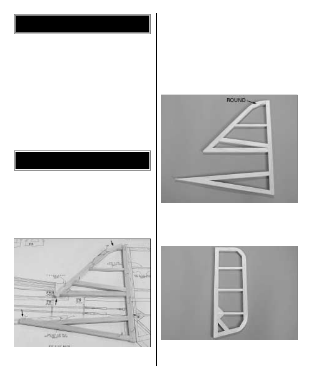
❏
3. Use medium CA to build the fin from three
3/8" x 1/2" x 30" [9.5 x 13 x 760mm] balsa sticks
and one 1/4" x 3/8" x 18" [6.4 x 9.5 x 460mm]
balsa stick. Use T-pins to hold the sticks down as
you proceed. Note the angles on the ends of
some of the sticks (indicated by the arrows in
the photo) are not cut until the next step. Also
note the 3/32" [2.4mm] vent holes (shown on
the plan) that have been pre drilled through the
sticks to allow air to escape during covering. It’s
easiest to drill these holes before the sticks are
glued into position.
❏
4. Remove the fin from the plan. Cut the rest
of the angles on the sticks that weren’t cut
earlier. Sand both sides of the fin flat and
smooth
and round the tip.
❏
5. Build the rudder using the sticks left over
from the fin plus an additional 3/8" x 1/2" x 30"
[9.5 x 13 x 760mm] balsa stick.
BUILD THE TAIL SURFACES
LABEL THE PARTS
11
Page 12
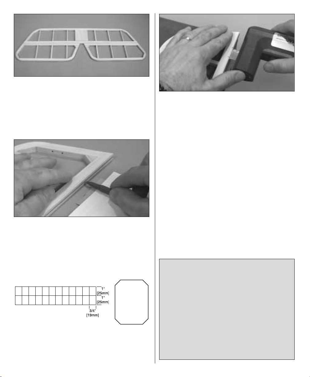
❏
6. Reposition the plan so the stab is over the
building board. Don’t forget to cover it with
Plan Protector or wax paper. Use the sticks left
over from the fin and rudder plus four more 3/8"
x 1/2" x 30" [9.5 x 13 x 760mm] balsa sticks and
three more 1/4" x 3/8" x 18" [6.4 x 9.5 x 460mm]
balsa sticks to build the stab and elevators.
❏
7. Use a ballpoint pen to mark centerlines on
the trailing edge of the fin and stab and on the
leading edges of the rudder and elevators.
Hint: Rest the pen on a thin stack of plywood or
cardstock. Adjust the thickness of the stack until
the pen is on-center.
❏
8. Cut twelve 3/4" x 1" [19 x 25mm] hinges
from the 2" x 9" [51 x 230mm] CA hinge strip
supplied with this kit. Snip the corners off so
they go in easier.
❏
9. Use a Great Planes Slot Machine to cut the
hinge slots on the centerlines in the stab and
elevators and in the fin and rudder where
shown on the plan. If you do not have a Slot
Machine, follow the procedure that follows to
cut the hinge slots with a hobby knife and a #11
blade
(or run to the hobby shop and buy a Slot
Machine!).
NOTES ABOUT CA HINGES
This kit is supplied with CA hinge material
consisting of a 3-layer lamination of Mylar
and polyester specially made for hinging
model airplanes. When properly installed,
this type of CA hinge provides the best
combination of strength, durability and easy
installation. We use these hinges on all our
models, but it is essential to install them
correctly. Follow the hinging instructions in
this manual for the best result. The
techniques shown have been developed to
ensure thorough and secure gluing.
12
Page 13
❏
10. Temporarily join the rudder to the fin and
the elevators to the stab with the hinges. Make
adjustments to the hinge slots where
necessary.
With the control surfaces temporarily joined,
sand the outer edges of all the parts round
(except for where they are hinged).
❏
11. Remove all the hinges. Use a razor plane
followed by a bar sander to shape the leading
edge of the rudder and elevators to a “V” as
shown on the plan.
Set the tail parts aside and proceed to the wing.
❏
1. Roll the wing plan inside out so it will lay
flat. Position the plan so the bottom center
panel is over your flat building board (or cut it
from the wing plan). Cover the plan with Plan
Protector or wax paper so glue will not adhere
to it.
❏
2. Cut a 1/8" x 1/4" x 24" [3.2 x 6.4 x 610mm]
basswood stick into two 12" [305mm] pieces.
BUILD THE BOTTOM
CENTER PANEL
BUILD THE WING
How to cut hinge slots with a hobby knife
When using a hobby knife to cut hinge slots,
one of the most common mistakes made by
modelers is making the slots too tight. This
restricts the flow of CA to the back of the
hinges. Another mistake made when
installing hinges is not using enough glue to
fully secure the hinge over its entire surface
area. This results in hinges that are only
tack
glued
. Follow these steps to cut hinge slots
with a hobby knife:
A. Using the centerline as a guide, cut one of
the hinge slots where shown on the plan with
a #11 blade. Begin by cutting a shallow slit.
Make three or four cuts along the same line,
going slightly deeper each time. As you
proceed, be certain to go straight into the
wood and move the knife from side to side
until the slot is wide enough to accommodate
a hinge.
B. Test fit a hinge into the slot. If the hinge
does not slide into the slot easily, remove the
hinge and reinsert the knife, working the
blade back and forth a few times to provide
more clearance (it’s the back edge of the
blade that does the widening).
C. Cut the rest of the hinge slots the same
way.
13
Page 14
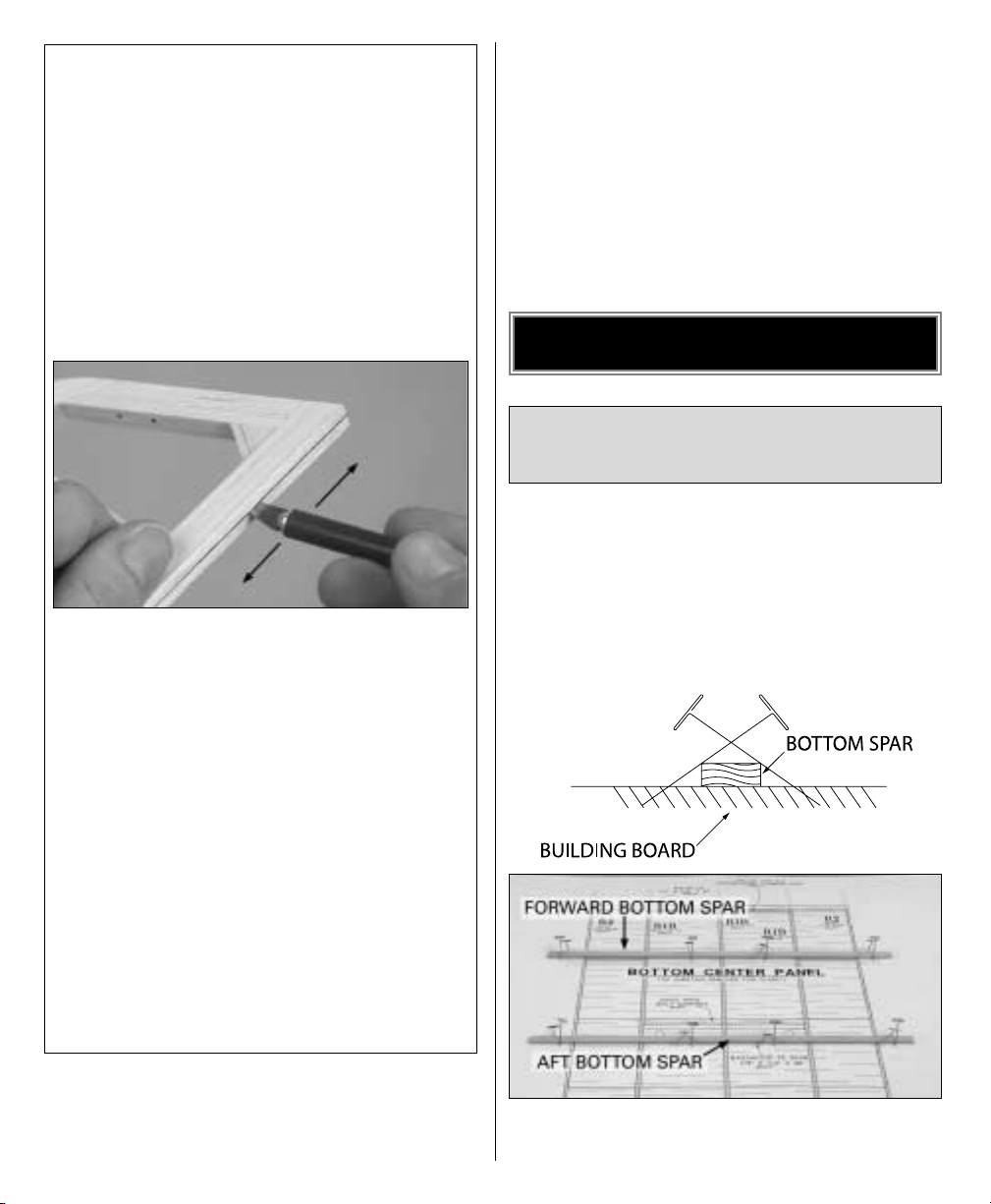
Use the “crossed-pin” technique to pin the
spars to the plan over the location for the
forward and aft bottom spars.
❏
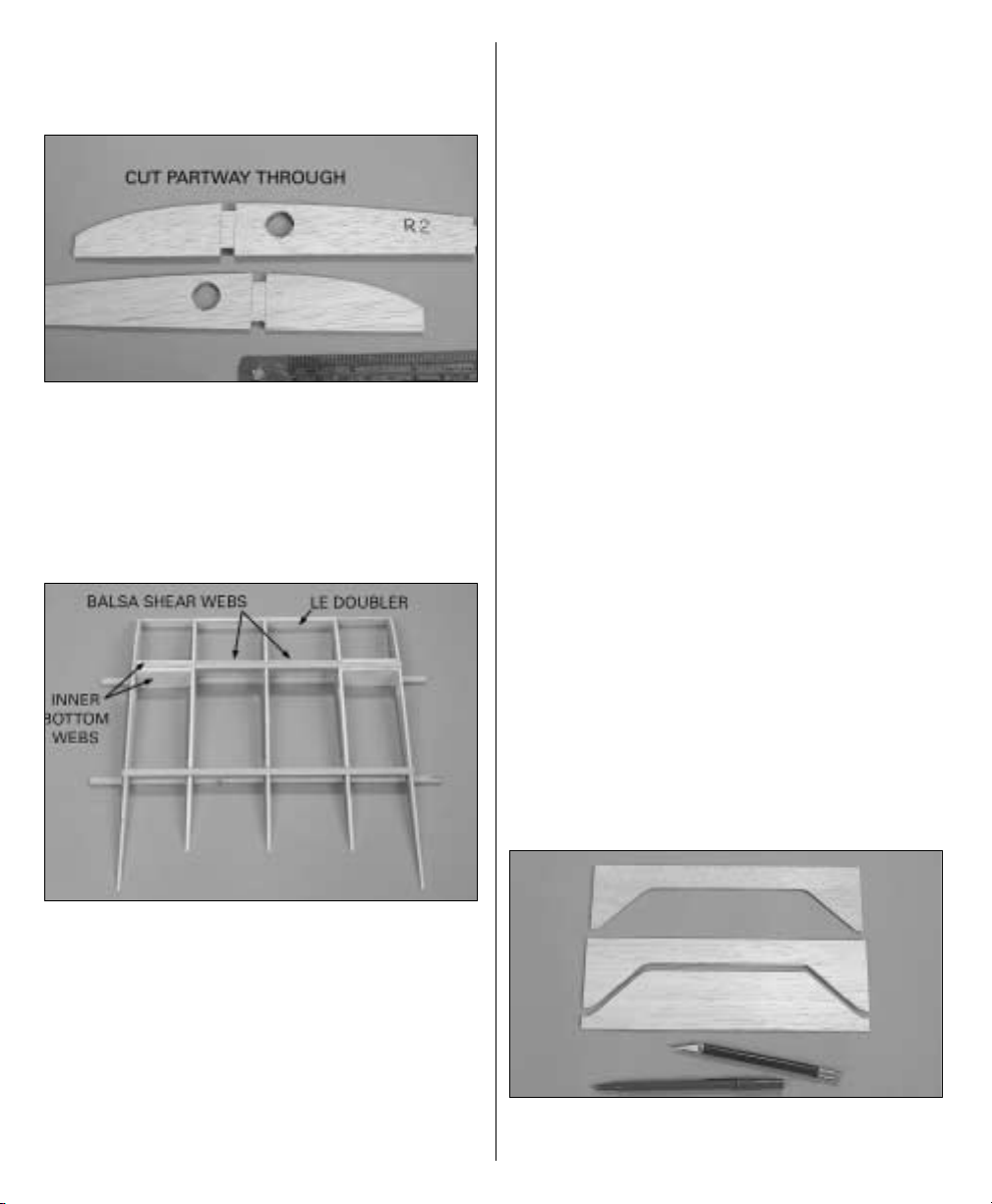
3. Use a hobby knife and a straightedge to
cut partway through opposite sides of both
die-cut 3/32" [2.4mm] balsa wing ribs R2
between the forward spar notches.
Refer to this photo for the following
six steps.
❏
4. With the cuts made in the previous step
facing outward, glue both R2 ribs and the three
die-cut 1/8" [3.2mm] plywood R1B ribs to the
spars over their location on the plan. Use a
small builder’s triangle to hold the ribs vertical
as you glue. It is especially important that the
outer R2 ribs are vertical.
❏
5. Cut another 1/8" x 1/4" x 24" [3.2 x 6.4 x
610mm] basswood stick into two 9-5/8"
[245mm]
pieces. Glue them into the notches in the top of
the ribs for the forward and aft top spars. The
same as when gluing the ribs to the bottom
spars, use a small builder’s triangle to hold the
ribs–especially the outer ribs–vertical as you
glue.
❏
6. Glue the four die-cut 1/8" [3.2mm] plywood
inner bottom webs (labeled “IBW” on the
part) to the spars and ribs where shown. Glue
the die-cut 1/8" [3.2mm] plywood leading
edge doubler (labeled “LED” on the part) to
the R1B ribs, then cut the sub-leading edge
from a 1/16" x 3/8" x 24" [1.6 x 9.5 x 610mm]
balsa stick and glue it into position. Save the
remainder of the stick for the top center panel.
❏
7. Cut 4" from each of three 3/32" x 3" x 24"
[2.4 x 76 x 610mm] balsa sheets. After doing so,
you will have three 3/32" x 3" x 4" [2.4 x 76 x
102mm] balsa sheets. These are to be used for
shear webs. You will also have three 3/32" x 3"
x 20" [2.4 x 76 x 510mm] balsa sheets to be used
for sheeting the center panel.
❏
8. From one of the 3/32" x 3" x 4" [2.4 x 76 x
102mm] balsa sheets, cut two shear webs for
the front of the forward spars. Note that the
grain is vertical. Glue the shear webs into
position.
❏
9. Remove the bottom inner panel from the
plan. Use a bar sander to sand off any glue
bumps or uneven surfaces from the bottom of
the panel.
❏
10. Using one of the die-cut 3/32" [2.4mm]
balsa center panel trailing edges (labeled
14
Page 15
“CTE”) as a pattern, make an additional center
panel trailing edge from a 3/32" x 3" x 24" [2.4 x
76 x 610mm] balsa sheet. Save the remainder of
the sheet for the top center panel.
❏
11. Make the top and bottom skins for
sheeting the center panel from the three 3/32" x
3" x 20" [2.4 x 76 x 510mm] balsa sheets you cut
earlier and the center panel trailing edges.
Make the sheets slightly oversize to allow for
trimming later.
❏
12. Working over a flat surface, glue the
center panel structure to the skin that has the
harder, die-cut center panel trailing edge.
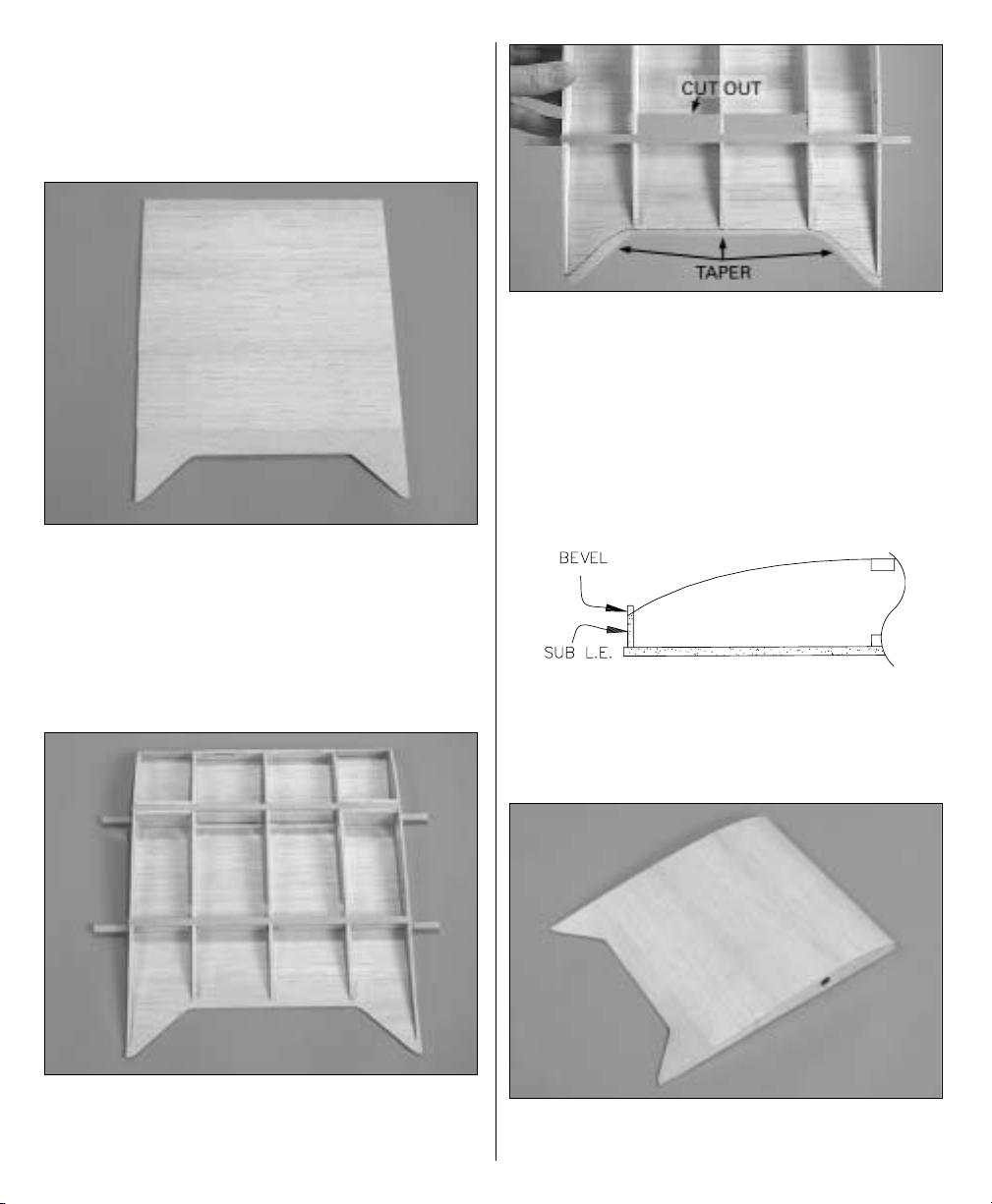
❏ 13. Cut out the bottom sheeting to
accommodate
the grooved 1/2" x 3/4" x 5-3/8" [12.7 x 19.1 x
137mm] basswood aft landing gear block.
Note the difference between the aft and the
forward landing gear blocks; the groove in the
forward landing gear block is centered, while
the groove in the aft landing gear block is not
centered. Use a bar sander to taper the trailing
edge of the sheeting using the ribs as a guide.
❏
14. Use a bar sander to lightly sand the top of
the center panel so all the ribs and spars are
even. Also be certain to bevel the top of the sub
leading edge to match the angle of the ribs.
❏
15. Sheet the top of the center panel with the
other skin. After the glue dries, sand the spars
15
Page 16
and sheeting even with the ends. Sand the front
of the sheeting even with the sub leading edge.
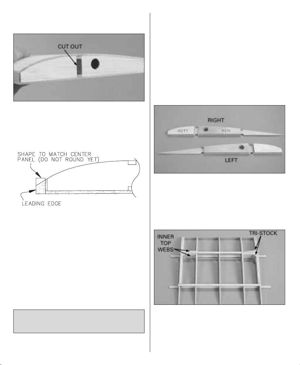
❏
16. Cut the rest of the way through the lines
in the ribs on both ends of the center panel and
remove the balsa between the spars. Set the
bottom center panel aside.
❏
17. Cut the center panel leading edge
slightly longer than required from a 1/4" x 5/8" x
24" [6.4 x 15.9 x 610mm] balsa stick (save the
remainder of the stick for the top center panel).
Glue the leading edge to the front of the center
panel. Sand the ends and top of the leading
edge even with the center panel, but do not
round the leading edge until instructed to do
so.
That’s it for the bottom center panel. Set it aside
and work on the top center panel.
❏
1. Position the plan so the top center panel
is over your flat building board (or cut it from
the wing plan) and cover it with Plan Protector
or wax paper.
❏
2. The same as was done for the ribs on the
ends of the bottom center panel, cut partway
through opposite sides of both die-cut 3/32"
[2.4mm] balsa wing ribs R2 for the ends of the
top center panel between the forward spar
notches.
Be certain to refer to the wing plan while
performing step 3.
❏
3. Make the rib assemblies for both ends of
the top center panel as shown on the plan by
gluing together the die-cut 3/32" [2.4mm] balsa
ribs R2, the die-cut 1/16" plywood ribs R2B and
the die-cut 1/8" [3.2mm] plywood ribs R2T1. Be
certain to make a right and a left.
❏
4. Build the top center panel the same as
the bottom center panel. After gluing in the diecut 1/8" [3.2mm] plywood inner top webs
(ITW) add the triangle stock reinforcements cut
from the 3/8" x 17-7/8" [9.5 x 455mm] balsa
tri-stock. Make another center panel trailing
BUILD THE TOP
CENTER PANEL
16
Page 17
edge using the 3/32" x 3" [2.4 x 75mm] balsa
sheet left over from making the first center
panel trailing edge for the bottom center panel.
Make the skins and save the leftover pieces for
shear webs. Glue the top center panel to the
bottom skin, add the balsa shear webs, then
glue the top skin to the panel. Sand the ends of
the sheeting even with the ribs and sub leading
edge, then cut out the ribs on the ends of the
panel between the spars. Add the leading edge
cut from the 1/4" x 5/8" [6.4 x 15.9mm] balsa
stick left over from the leading edge on the
bottom center panel, then sand to match the
shape of the ribs. Set the top center panel aside.
Note: All four outer panels are nearly identical.
The only differences are that, obviously, there
are two rights and two lefts. The only difference
between the top and bottom panels is the 1/16"
[1.6mm] plywood rib assemblies at R4 where
the wing struts connect.
Start with the left, bottom outer panel first.
❏ ❏ ❏ ❏
1. Position the left outer wing panel
plan over your flat building board and cover it
with wax paper or Plan Protector.
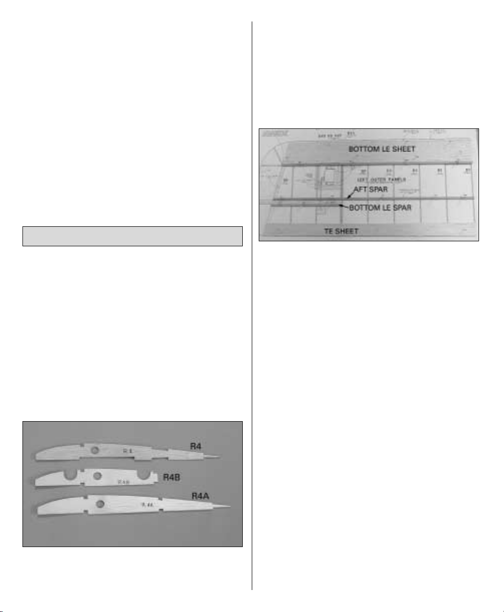
❏ ❏ ❏ ❏
2. Referring to the illustrations near
the leading edge of the left panel on the wing
plan, use medium CA to glue together the die-
cut 1/8" [3.2mm] plywood rib R4A, the die-cut
1/16" plywood rib R4B and the die-cut 3/32"
[2.4mm] balsa rib R4. Be certain you are
looking at the correct illustration for the wing
panel you are working on (top or bottom).
Refer to this photo for the following
six steps.
❏ ❏ ❏ ❏
3. Cut the forward spar 1/8" [3mm]
longer than shown on the plan from a 1/8" x 1/4"
x 24" [3.2 x 6.4 x 610mm] basswood stick. Cut
the aft spar 1/8" [3mm] longer than shown on
the plan from a 1/8" x 1/4" x 30" [3.2 x 6.4 x
760mm] basswood stick.
❏ ❏ ❏ ❏
4. Cut the bottom leading edge
sheet 1/8" [3mm] longer than shown on the
plan from a 3/32" x 3" x 24" [2.4 x 76mm x
610mm] balsa sheet.
❏ ❏ ❏ ❏
5. Glue the forward spar to the top of
the leading edge sheet along the aft edge. Pin
the spar and sheeting to the plan.
❏ ❏ ❏ ❏
6. Cut 4-1/2" [115mm] from a 3/32" x
4" x 30" [2.4 x 100 x 760mm] balsa sheet. Add
the 4-1/2" [115mm] sheet to the stack of sheets
you’ve been saving for shear webs.
❏ ❏ ❏ ❏
7. Cut the 25-1/2" [650mm] sheet from
the previous step into two 1-1/2" [38mm] wide
strips to make the trailing edge sheets. The
same as was done for the leading edge sheet,
cut the trailing edge sheet 1/8" [3mm] longer
than shown and pin to the plan. Save the other
1-1/2" [38mm] wide strip for the top.
BUILD THE OUTER PANELS
17
Page 18

❏ ❏ ❏ ❏
8. Cut the bottom aileron spar from
a 1/8" x 1/4" x 24" [3.2 x 6.4 x 610mm] basswood
stick as shown on the plan, then pin it over its
location. Save the remainder of the stick for
the top.
❏ ❏ ❏ ❏
9. Glue all the ribs except for rib R3
at the root of the panel and rib R6 at the
tip of the panel to the spars and sheeting.
❏ ❏ ❏ ❏
10. Cut the cap strips that go under
rib R6 from a 3/32" x 3/8" x 24" [2.4 x 9.5 x
610mm] balsa stick, then glue them into
position. Glue rib R6 to the assembly.
❏ ❏ ❏ ❏
11. The same as was done for the ribs
on the ends of the center panels, use a hobby
knife and a straightedge to cut partway through
the outside of the remaining rib R3 that goes on
the end of the outer panel you are working on.
Refer to this photo for the following
two steps.
❏ ❏ ❏ ❏
12. Without using any glue, add the
following parts to the assembly:
• Rib R3 that goes on the root end of the panel.
• The top, forward spar cut from a 1/8" x 1/4" x
24" [3.2 x 6.4 x 610mm] basswood stick.
• The top, aft spar cut from a 1/8" x 1/4" x 30"
[3.2 x 6.4 x 760mm] basswood stick.
• The die-cut 1/8" [3.2mm] plywood outer
webs (OW) that go on the forward spars.
❏ ❏ ❏ ❏
13. Using the die-cut 1/8" [3.2mm]
plywood dihedral gauge (DG) and the outer
webs to set rib R3 at the correct angle, glue rib
R3 to the bottom spars and sheeting only.
❏ ❏ ❏ ❏
14. Glue the top spars to all the ribs.
Glue the outer webs to the spars and ribs. Note
that the top of the outer web on the back of the
spars is even with the top spar.
18
Page 19
Refer to this photo for the following
three steps.
❏ ❏ ❏ ❏
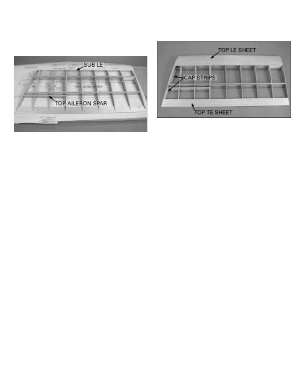
15. Cut the top aileron spar from the
remainder of the 1/8" x 1/4" x 24" [3.2 x 6.4 x
610mm] basswood stick used for the bottom
aileron spar, then glue it into position.
❏ ❏ ❏ ❏
16. Cut the sub-leading edge from a
1/16" x 3/8" x 24" [1.6 x 6.5 x 610mm] balsa stick,
then glue it into position.
❏ ❏ ❏ ❏
17. Since the plan you are working
over is covered by the structure, refer to the
other outer panel plan you are not working over
to view the shear webs. Cut the shear webs
from two of the 3/32" x 3" x 4" [2.4 x 76 x
100mm] balsa sheets leftover from making the
center panel skins. Remove any T-pins that are
in the way, then glue the shear webs to the front
of the forward spars. Note that the grain on the
shear webs is vertical.
❏ ❏ ❏ ❏
18. Use a bar sander to sand the sub
leading edge to match the angle on the top of
the ribs.
Refer to this photo for the following
four steps.
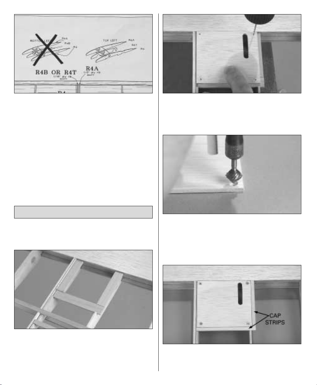
❏ ❏ ❏ ❏
19. Cut the top leading edge sheet
from a 3/32" x 3" x 24" [2.4 x 76 x 610mm] balsa
sheet. Glue the sheet into position.
❏ ❏ ❏ ❏
20. Remove the outer panel from the
building board. The same as was done on the
center panel trailing edges, taper the outer
panel trailing edge to accommodate the top
trailing edge sheet. Glue the top trailing edge
sheet into position.
❏ ❏ ❏ ❏
21. Cut the cap strips that go over rib
R6 at the wing tip from the remainder of 3/32" x
3/8" balsa stick used for the cap strips on the
bottom of the wing. Glue the cap strips into
position.
❏ ❏ ❏ ❏
22. Use a bar sander to sand the
sheeting, spars and cap strips even with the
ribs on both ends of the outer panel.
❏ ❏ ❏ ❏
23. Cut the leading edge from a 1/4"
x 5/8" x 24" [6.4 x 16 x 610mm] balsa stick, then
glue it into position. Sand the leading edge to
match the shape of the outer panel, but do not
round until instructed to do so.
19
Page 20
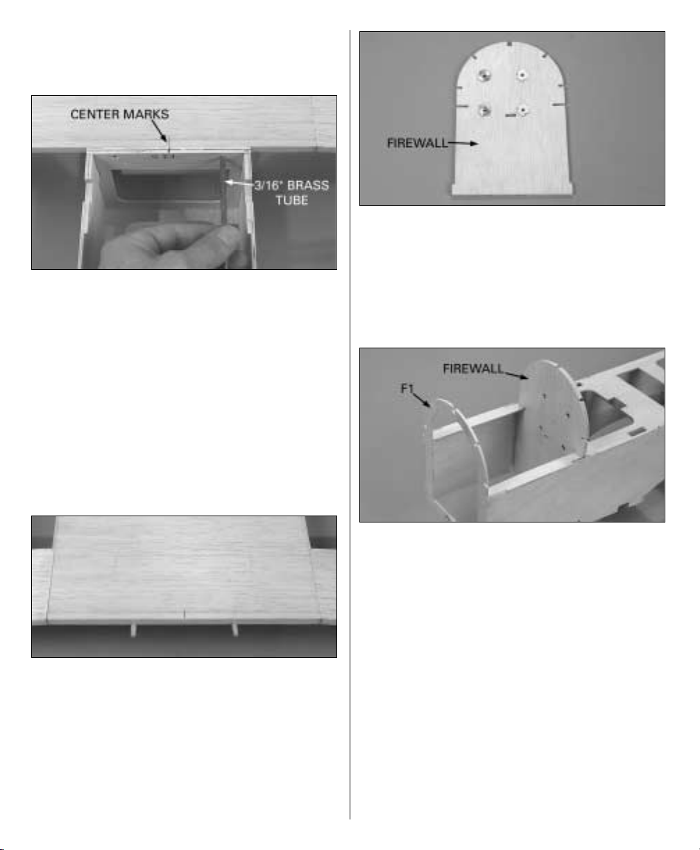
❏ ❏ ❏ ❏
24. Repeat the same steps to build the
left top panel, then switch to the other plan
and build both right panels. Be certain to
refer to the illustrations depicting which
R4 assemblies to use for the panel you are
working on. Hint: Use a thick magic marker to
put a bold “X” through the illustration of the
R4 rib assembly already completed, so you do
not inadvertently build the same one.
The same as we’ve been doing all along, start
with the left, bottom outer panel.
❏ ❏ ❏ ❏
1. Cut the servo hatch rails as
shown on the plan from the 1/8" x 1/2" x 18" [3.2
x 12.7 x 460mm] basswood stick, then glue
them into position. Save the remainder of the
stick for the servo hatch rails for the top panel.
❏ ❏ ❏ ❏ 2. Place a die-cut 1/8" [3.2mm]
plywood
servo hatch (HC) over the rails as shown on
the plan. Drill 1/16" [1.6mm] holes through the
hatch and the rails.
❏ ❏ ❏ ❏
3. Enlarge the holes in the hatch
only with a 3/32" [2.4mm] drill. Use a small
countersink bit or Dremel #178 cutting bit to
countersink the holes in the hatch for the #2 x
3/8" [9.5mm] flat-head screws.
❏ ❏ ❏ ❏
4. Mount the hatch with four #2 x 3/8"
[9.5mm] flat-head screws. Cut the cap strips
for the edges of the hatch from a 3/32" x 3/16" x
MOUNT THE AILERON SERVOS
20
Page 21

30" [2.4 x 4.8 x 760mm] balsa stick. Glue the cap
strips to the rails next to the hatch.
❏ ❏ ❏ ❏
5. Mount the aileron servo to two 3/8"
x 3/4" x 3/4" [9.5 x 19 x 19mm] basswood servo
mount blocks by drilling 1/16" [1.6mm] holes
into the blocks. Run the servo screws (that came
with the servo) in and out of the holes in the
blocks a few times to form some “threads.”
Remove the screws, add a few drops of thin CA
to the holes and allow to fully harden. Mount
the servo to the blocks with the screws.
❏ ❏ ❏ ❏
6. Make a one-arm servo arm by
cutting off three of the arms. Install the arm on
the servo.
❏ ❏ ❏ ❏
7. Use a ballpoint pen to mark the
forward edge of the aft servo hatch rail onto the
inside of the hatch. Remove the hatch cover
from the wing. Use 30-minute epoxy to securely
glue the servo mount blocks to the hatch with
the servo arm centered in the slot. Be certain
the aft servo block is not over the line depicting
the aft servo hatch rail.
❏ ❏ ❏ ❏
8. While the epoxy is hardening and
the hatch is out of the wing panel, add a few
drops
of thin CA to the screw holes in the hatch rails.
❏ ❏ ❏ ❏
9. After the epoxy hardens, mount the
hatch with the servo to the wing. Glue the diecut 1/8" [3.2mm] plywood top and bottom
control horn mounts (TCH, BCH) into
position.
You may return to the beginning of this section
and mount the servos in the remaining three
outer panels now, or continue with the first
panel and proceed to the wing tip.
❏ ❏ ❏ ❏
1. Working over the plan, glue both
parts of the die-cut 1/8" [3.2mm] balsa wing
tips (WT) together.
BUILD THE WING TIPS
21
Page 22

❏ ❏ ❏ ❏
2. Place the wing tip over the plan and
mark the location of the tip ribs. Glue one of the
die-cut 3/32" [2.4mm] balsa tip ribs (TR) to the
wing tip. The outer edge of the tip rib should
align with the outer edge of the wing tip.
Maintaining a 90° angle as shown, sand the
inner edge of the tip rib even with the tip.
❏ ❏ ❏ ❏
3. Glue the other tip rib into position
and sand the end as well.
Do not use any glue in the following
two steps.
❏ ❏ ❏ ❏
4. Position the wing tip on the end of
the wing. Center the gap between the forward
and aft parts of the tip between the aileron
spars and the aft spars.
❏ ❏ ❏ ❏
5. Center the trailing edge of the wing
tip on the trailing edge of the wing. Center the
leading edge of the wing tip on the leading
edge of the wing. For clarity in the photo, a
reference line has been drawn on the end of the
wing noting where the center of the leading
edge
will be
when the panel is finally rounded
to shape.
❏ ❏ ❏ ❏
6. Securely glue the tip and tip ribs to
the end of the wing in this position.
❏ ❏ ❏ ❏
7. Make the tip ribs for the bottom of
the wing tip from leftover 3/32" [2.4mm] balsa
and glue them into position. Sand the top and
bottom tip ribs even with the top and bottom of
the wing and the wing tip.
22
Page 23

❏ ❏ ❏ ❏
8. Use a razor saw to cut the aileron
from the outer panel.
❏ ❏ ❏ ❏
9. Trim the leftover portions of the ribs
and wing tip even with the outer panel and the
aileron spars. Cut the outer trailing edge and
the aileron leading edge from a 1/4" x 7/8" x
24" [6.4 x 22.2 x 610mm] balsa stick, then glue
them into position.
❏ ❏ ❏ ❏
10. Sand the aileron leading edge
even with the aileron and sand the outer trailing
edge even with the wing. Place the wing and
the aileron flat on the workbench. Holding them
down, sand the wing trailing edge and the
aileron leading edge even with each other.
❏ ❏ ❏ ❏
11. The same as was done on the tail
surfaces, mark a centerline on the outer trailing
edge. On the model shown, a ballpoint pen
supported by a piece of 1/4" [6.4mm] balsa was
used to mark the lines (the lines don’t have to
be exactly on center–it’s more important that
the lines accurately align with each other). Mark
a centerline on the aileron leading edge the
same way.
❏ ❏ ❏ ❏
12. Cut the hinge slots, then bevel the
leading edge of the aileron to allow for control
throw movement. Test fit the aileron to the wing
with the hinges. Make adjustments where
necessary.
❏ ❏ ❏ ❏
13. Make the aileron pushrod from
the hardware shown in the photo and on the
23
Page 24

plan. Drill 1/16" [1.6mm] holes for the control
horn screws. Run the #2 x 3/8" [9.5mm] screws
in and out of the control horn mount, remove
the screws, then add a few drops of thin CA to
the holes and allow to fully harden. Mount the
control horn and hook up the aileron. Make
adjustments where necessary.
Other than final-sanding (which will be done
after the outer panels are joined to the center
panel), the outer panels are now completed. You
know the routine…return to the beginning and
mount the servos and finish the wing tips on
the remaining three outer panels the same way.
❏
1. Make one 1/4" [6.4mm]-thick wing joiner
by gluing together two die-cut 1/8" [3.2mm]
plywood wing joiners (WJ). Make three more
wing joiners the same way.
❏ ❏
2. Test fit two joiners in the panels of the
bottom wing. It may be necessary to sand the
edges of the joiners to get them to fit. Be
certain the panels you are test fitting are
matched up correctly (bottom center panel to
bottom outer panels)!
❏ ❏
3. Lay the bottom center panel on your flat
workbench. Place weights on top of the center
panel to hold it down. Use balsa blocks or
something similar to raise both ends of the
wing under rib R6 two inches. Check the fit of
the outer panels to the center panel and be
certain the leading and trailing edges align.
Note: Join only one outer panel to the center
panel at time. Do not attempt to join both outer
panels to the center panel simultaneously. Mix
a new batch of epoxy for joining each wing
panel. Otherwise, the epoxy may begin to
harden while you are working.
Read through the following steps before
beginning and gather all the items used so
you’ll have everything on-hand before you
begin (you’re doing that with every step
anyway–right?)
❏ ❏ 4. Cut a few paper towels into
approximately
2" [50mm] squares for epoxy clean up. Mix up
1/2 oz. [15cc] of 30-minute epoxy in a mixing
JOIN THE WING PANELS
24
Page 25

cup. Use an epoxy brush to apply a film of
epoxy to the joining ribs on the end of the
bottom left panel and the bottom center
panel. Set the panels on-end so the epoxy will
not run. Coat the joiner with epoxy as well. Add
milled glass fibers or microballoons to the
remainder of the epoxy mixture. Use a piece of
wire to apply the epoxy and microballoons
mixture inside both panels between the spars
where the joiner fits. Insert the joiner in one of
the panels. Use the wire to wipe away excess
epoxy that squeezes out, then join the center
panel again, wiping away excess epoxy.
Immediately
proceed to the next step.
❏ ❏
5. Lay the joined panels on top of your
building board covered with wax paper. Place
weights on top of the center panel to hold it
down (small plastic bags containing lead shot
work well for this). Use a balsa block or
something similar to prop up the end of the
wing under rib R6 2" [51mm]. Use large balsa
sticks T-pinned to the building board (indicated
by arrows in the top photo) to tightly squeeze
the panels together. Use a few paper towel
squares dampened with alcohol to wipe away
any more epoxy that squeezes out of the joint.
Make certain the leading and trailing edges of
the joining panels align. Do not disturb the
wing until the epoxy has fully hardened.
❏ ❏
6. Proceed and join the top left panel to the
top center panel. After the epoxy joining the left
panels has hardened, join the right panels.
One last thing before moving onto the
fuselage…
❏ ❏
7. In the bottom wing, cut slots in the top
of the sheeting over the openings for the
forward strut retainers. Glue pieces of
leftover 1/8" x 1/4" [3.2 x 6.4mm] balsa to both
sides of the ribs to support the covering around
the aft strut retainers. Repeat the same
procedure on the bottom of the top wing. Cut
the slots for the strut retainers in the center
panel of the top wing.
Now that the wings are framed-up and joined
we’ll get started on the fuse. The wings will be
completed and finish-sanded later.
❏
1. Place the side view of the fuselage plan
over your flat building board and cover it with
Plan Protector or wax paper.
BUILD THE FUSELAGE SIDES
BUILD THE FUSELAGE
25
Page 26

❏
2. Make a fuselage side by gluing together a
die-cut 1/8" [3.2mm] plywood fuselage side
(FS), two 1/8" x 1/2" x 24" [3.2 x 12.7 x 610mm]
balsa sticks and the die-cut 1/8" [3.2mm]
plywood stab saddle (SS). Use T-pins to hold
the parts over their location on the plan as you
proceed.
❏
3. After the glue from the previous step has
hardened, remove the fuselage side from the
plan. Make another fuselage side the same way.
After the glue dries, sand both assemblies flat
and even.
❏
4. Switching to the fuselage bottom view,
build the fuselage top over the plan from the
die-cut 1/8" [3.2mm] plywood forward and aft
fuselage tops (FFT, AFT) and two 1/8" x 1/2" x
24" [3.2 x 12.7 x 610mm] balsa sticks. Remove
the fuselage top from the plan, then sand flat
and even.
❏
5. Arrange both fuselage sides as shown in
the photo. Use a ballpoint pen to write “IN” on
the outward facing sides. Glue a die-cut 1/8"
[3.2mm] plywood fuselage side doubler
(FSD) to the inside of each fuse side.
❏
6. Glue the die-cut 1/8" [3.2mm] plywood
former F3D to the front of die-cut 1/8" [3.2mm]
plywood former F3.
26
Page 27

Refer to these photos for the following
four steps.
❏
7. Pin the fuse top back to the plan with Plan
Protector underneath. Without using any glue,
join both fuselage sides to the fuse top. Use
balsa sticks T-pinned to the plan to hold the fuse
sides tightly to the fuse top.
❏ 8. Add die-cut 1/8" [3.2mm] plywood
formers
F3 through F9 to the assembly.
❏
9. Cut the four 3/16" x 36" [4.8 x 915mm]
pushrod tubes to a length of 30-1/2" [775mm].
Save one of the remaining 5-1/2" [140mm]
pieces for the throttle pushrod tube. Roughen
the outside of the tubes with coarse sandpaper
so glue will adhere, then slide them through the
holes in the formers as shown on the plan.
(Some of the following photos may only show
three tubes.)
❏
10. Making certain all the parts fit correctly
and that the fuse top is fully contacting the
plan, use medium CA to carefully glue all the
formers to the fuse sides and fuse top. Glue the
fuselage sides to the fuse top from F3 aft. Do
not glue the fuselage sides to the fuselage top
from F3 forward until instructed to do so. When
gluing the fuse sides to the fuse top aft of
former F9, use a builder’s square to hold the
fuselage sides vertical.
❏
11. Use medium CA to glue the pushrod tubes
to the formers. Glue the aft end of the pushrods
to the stab saddles and fill the slot with 30minute epoxy mixed with microballoons.
❏
12. Sheet the bottom of the fuselage from F5
aft using the 1/8" x 3" x 36" [3.2 x 75 x 915mm]
balsa sheet.
❏
13. Remove the fuselage from the building
board. Sand the bottom sheeting and the
pushrod tubes even with the fuselage sides.
❏
14. Place the bottom wing in the wing saddle.
Taking accurate measurements, mark the center
Note: Though there are two elevator
pushrods and one rudder pushrod, four
pushrod tubes are installed in the
fuselage–the unused pushrod tube is for the
receiver antenna. The rudder servo will be
mounted to the side of the fuselage opposite
the throttle servo.
27
Page 28
of the bottom wing panel on the leading edge
and the center of the fuselage at former F3.
Center the wing in the fuselage, aligning the
marks.
❏
15. Using the holes in F3 as a guide, use a
3/16" [4.8mm] brass tube sharpened on the end
to cut holes through the balsa leading edge of
the wing for the wing dowels. (To sharpen the
end of a brass tube, use a rotary tool with a
cutoff wheel or a file to bevel the outside of the
tube, and use a #11 hobby knife to bevel the
inside of the tube.)
❏
16. Remove the wing from the fuselage. Use
the brass tube or a 3/16" [4.8mm] drill to drill
holes the rest of the way through the wing and
into the shear webs inside.
❏
17. Round one end of both 3/16" [4.8mm]
wing dowels. Without using any glue, fit the
dowels into the wing, then test fit the wing to
the fuse. Do not glue the dowels into the wing
until instructed to do so.
❏
18. Glue both die-cut 1/8" [3.2mm] plywood
formers F2 together. From now on this
assembly will be referred to as the firewall.
❏
19. Drill 13/64" [5.2mm] holes through the
four punchmarks in the front of the firewall.
Insert four 8-32 blind nuts into the holes in the
back of the firewall and lightly tap them in with
a hammer. Carefully add a few drops of thin CA
around the nuts to permanently hold them in.
❏
20. Glue the die-cut 1/8" [3.2mm] plywood
former F1 to the front of the fuselage.
❏
21. Fit the firewall into position. Note the
angle on the front of the fuse top where it
contacts the firewall to provide the correct
amount of right thrust. Glue the firewall into the
fuselage with 30-minute epoxy using clamps
where necessary to securely hold it into
position.
❏
22. Sand the bottom of former F3 and the
firewall even with the bottom of the fuse sides.
Glue the fuselage top to the fuselage sides from
F3 forward.
28
Page 29

❏
23. Test fit, then use 30-minute epoxy to glue
the 1/4" x 1-1/2" x 5-1/8" [6.4 x 38 x 130mm]
wing bolt plate and the 1/2" x 3/4" x 5-3/8"
basswood forward landing gear block into
position.
Refer to these photos for the following
five steps.
❏
1. Test fit the die-cut 1/8" [3.2mm] plywood
tank tray (TT) in the fuselage. Cut notches in
the front of the tray to accommodate the blind
nuts in the back of the firewall.
❏
2. Glue together two pieces of leftover 1/8" x
1/4" [3.2 x 6.4mm] basswood from the wing
spars to make a 1/4" x 1/4" [6.4 x 6.4mm]
mounting rail for the tank tray. Cut the rail to
a length of 3" [75mm]. Glue the rail to the back
of former 3 as shown on the plan.
❏
3. Drill 1/16" [1.6mm] holes through the aft
end of the tank tray and the rail. Remove the
tray. Enlarge the holes in the tray only with a
3/32" [2.4mm] drill.
❏
4. Use a couple of #64 rubber bands to mount
the fuel tank to the tray with a piece of 1/4"
6.4mm] R/C foam rubber in between. Mount the
tray in the fuselage with two #2 x 3/8" [9.5mm]
screws and #2 washers.
❏
5. Drill 1/4" [6.4mm] holes through the
firewall for the fuel lines. Temporarily connect
the fuel lines to the fuel tank.
❏
1. Make four strut mounts from the die-cut
1/8" [3.2mm] plywood and balsa parts shown
(all labeled “SM”). Note that both front
mounts are the same, but there is a right and
left rear mount.
INSTALL THE STRUT MOUNTS
MOUNT THE FUEL TANK
29
Page 30

❏
2. Using the 18" [460mm] basswood wing
struts to set the correct spacing, carefully glue
the die-cut 1/8" [3.2mm] balsa spacers (SM)
into all four strut mounts without inadvertently
gluing in the wing struts (two of the strut
mounts are shown in the photo).
❏ 3. Sand the spacers even with the strut
mounts.
❏ 4. Test fit the strut mounts and four wing
struts
into the fuselage. Slide the strut mounts as far
upward into the slots in the fuselage top as they
will go. Use the die-cut 1/8" [3.2mm] plywood
aft strut gauge (ASG) to set the aft strut
mounts at the correct angle. Use a 90° triangle
or a builder’s square to set the front strut
mounts. Make any adjustments required to get
the struts and strut mounts to fit correctly.
❏ 5. Securely glue the strut mounts into
position.
30
Page 31

❏
1. Mount the engine mount to the firewall
with four 8-32 x 1" [25mm] SHCS, #8 lock
washers and #8 flat washers and adjust it to fit
your engine. Position the engine on the mount
so the propeller (or a flat piece of wood with a
hole drilled in it) will be 1/2" to 3/4" [13 to
19mm] from the front of the fuselage.
❏
2. Use a Great Planes Dead Center™Hole
Locator (GPMR8130-shown in the photo) or
your own preferred method to mark the
locations of the holes for mounting the engine.
❏
3. Remove the engine and the engine mount
from the firewall. Drill #36 (or 7/64" [2.8mm])
holes through the mount at the marks, then tap
6-32 threads into the holes. Mount the engine
mount to the fuse, but center the mount on the
screws (the mount may have some side-to-side
play) before fully tightening them. Mount the
engine to the mount with 6-32 x 1" [25mm]
screws and #6 lock washers and flat washers.
Now that the engine is mounted, go ahead and
hook up the throttle and do the rest of the
hookups while the engine compartment is open
and easily accessible.
❏
4. Refer to the side view of the fuselage plan
and glue pieces of 1/8" x 1/2" balsa (left over
from making the fuselage sides) to the top of
both sides of the opening in the fuselage top for
the servo screws.
Refer to these photos while hooking up
the throttle.
❏
5. Plan the throttle hookup. The throttle servo
may be mounted on either side of the
fuselage–whichever aligns best with the
carburetor arm on the engine. Use a 3/16"
[4.8mm]
brass tube sharpened on the end or an
extended
3/16" [4.8mm] drill to drill a hole through the
firewall for the throttle pushrod tube.
❏
6. Use one of the leftover 5-1/2" [140mm]
pushrod tubes for the throttle. Slide the tube
into place. Hook up the throttle using a 2-56 x
MOUNT THE ENGINE
31
Page 32

18" [460mm] pushrod connected to the throttle
servo with a nylon clevis and connected to the
carburetor with a screw-lock pushrod
connector.
❏
7. Make a
brace
for the aft end of the throttle
tube by drilling a 3/16" [4.8mm] hole through a
piece of leftover plywood and gluing it to F3
as shown.
❏
8. Drill 1/16" [1.6mm] holes through the fuse
top for the throttle servo screws. Run the servo
mounting screws in and out of the holes a few
times, remove the screws, then add a few drops
of thin CA to the holes and allow to fully
harden. Mount the servo in the fuselage with
the screws.
Refer to these photos while finishing the
engine compartment.
❏
9. Should you decide to use a remote fuel
filler and a remote glow plug hookup, mount
them and cut access holes for them where
necessary. A mount for the fuel filler like the
one in the photo could be made from leftover
1/8" [3.2mm] plywood, or the fuel filler could be
mounted directly to the fuselage side. Cut a
hole for the needle valve as well.
❏
10. Temporarily mount the muffler to see how
it fits in the fuselage. An O.S. MAX “in” type
exhaust header pipe (OSMG2624) was used on
this model to aim the exhaust downward
without
having to cut holes in the fuselage sides.
❏
11. Cut the approximately 14" [360mm] piece
of triangle stock leftover from the top, center
wing panel into two pieces and glue them to
both sides of the front of the firewall and the
fuse sides.
❏
12. The same as was done for the tank tray,
glue together two pieces of 1/8" x 1/4" [3.2 x
6.4mm] basswood left over from the wing
spars. Cut the stick to the correct length and
glue it to the bottom of F1 along the aft edge
between the fuselage sides. Glue two more 1/8"
x 1/4" [3.2 x 6.4mm] basswood sticks along the
inside bottom edge of both fuselage sides
between the firewall and F1.
32
Page 33

❏ 1. Glue together both halves of the die-cut
1/8"
[3.2mm] balsa formers F5A, F6A and F7B.
❏
2. Glue formers F3A, F5A and F6A to the fuse
top as shown. Cut one 1/4" x 1/4" x 24" [6.4 x 6.4
x 610mm] balsa stick and four 1/8" x 1/4" x 24"
[3.2 x 6.4 x 610mm] balsa sticks to the correct
length, then glue them into the notches in
formers F1 through F5A. Note that the aft end of
all the sticks “ends” in the middle of F5A. As
you proceed, use a builders’ square to remove
warps and hold the stringers vertical. Glue the
stringers into the formers.
❏
3. Cut 4-1/2" [115mm] from each of four more
1/8" x 1/4" x 24" [3.2 x 6.4 x 610mm] balsa sticks
and 4-1/2" [115mm] from one 1/4" x 1/4" x 24"
[6.4 x 6.4 x 610mm] balsa stick. Save the longer
sticks for the aft end of the fuselage. Glue the
4-1/2" [115mm] sticks into the notches of
formers F5A and F6A. Cut, then sand the sticks
even with the back of F6A.
❏
4. The same as you made the skins for
sheeting the center panels, glue together two
1/8" x 3" x 30" [3.2 x 75 x 760mm] balsa sheets
to make a skin for one side of the front of the
fuselage. Glue together two more sheets for the
other side.
❏
5. Sand both skins flat and even, then cut
them to a length of 21" [535mm]. Save the
remainder of the sheets for sheeting over the
cockpit between formers F5A and F6A.
❏
6. Use a ballpoint pen to mark the location of
the struts on the fuselage sides. This will aid in
cutting the sheeting for the struts later. As
shown in the photo, glue strips of leftover 1/8"
BUILD THE TOP OF THE
FUSELAGE
33
Page 34

[3.2mm] balsa to the fuse top 3/32" [2.4mm]
from the edge between formers F1 and the
firewall and between the firewall and the front
strut mounts. Also glue 1/8" [3.2mm] strips of
balsa to the fuselage top between F3A and the
aft strut mount. These strips will support the
bottom of the sheeting when gluing it into
position.
❏
7. Sheet the left side first. Wet the outside of
one of the skins with a few squirts of window
cleaner or water, then position it on the fuse.
Bend the skin into position, then use a ballpoint
pen to mark the top of the skin where it is to be
cut over the center of the 1/4" x 1/4" [6.4 x
6.4mm] stringer on the top of the formers. Cut
the skin at the marks, then test fit and continue
to cut as necessary to get it to fit well. Glue the
skin into position with medium CA. Use tape
and clamps to hold it down until the glue
hardens.
❏
8. Glue the right skin into position the same
way. Sheet the cockpit area with the remaining
balsa sheeting left over from step 5.
❏
9. Before doing any sanding, use balsa filler
where required to fill any gaps in the sheeting.
Allow the filler to dry, then sand the sheeting
smooth and even.
❏ 10. Use the cockpit opening pattern
provided
on the plan to trace the outline of the cockpit
opening onto the fuse sheeting. Cut out the
opening.
34
Page 35

❏
11. Using the marks made earlier on the
fuselage sides, cut the sheeting to
accommodate
the wing struts. Start by making the openings
small, then carefully enlarge the holes until the
struts will fit.
❏
12. Glue the die-cut 1/8" [3.2mm] plywood
former F6B into position on the back of F6A.
Glue the laser-cut 1/8" [3.2mm] balsa former
F8B into position. Position, but do not glue
the die-cut 1/8" [3.2mm] balsa former F7B on
top of the fuselage. Insert the 1/4" x 1/4" [6.4 x
6.4mm] balsa stick left over from step 3 into the
notches of the three formers. Using a
straightedge,
adjust the position of F7B until the stringer is
straight. Glue F7B into that position. Glue the
stringer into the notches of the formers.
❏
13. Use the four remaining 1/8" x 1/4" [3.2 x
6.4mm] balsa sticks left over from step 3 and
four more 1/8" x 1/4" x 24" [3.2 x 6.4 x 610mm]
balsa sticks to make the stringers that run from
F6B to F8B and glue them into position.
❏
1. Sand the bottom of the bottom center wing
panel flat, smooth and even. Use 30-minute
epoxy to glue the aft landing gear block into
the bottom of the bottom center panel.
❏
2. Starting with a razor plane, followed by
sanding, shape the leading edge of the bottom
wing as shown on the plan.
❏
3. Install the 3/16" x 4" [20.6 x 100mm] wing
dowels in the bottom wing. You may
permanently
glue them in now with 30-minute epoxy, or wait
until after the wing is covered (which is the way
it was done with the model shown in this
manual). Fit the bottom wing into the fuse.
Place weights on the wing to hold it down.
❏
4. Taking accurate measurements, mark the
aft landing gear block where the holes for the
MOUNT THE BOTTOM WING
FINAL CONSTRUCTION
35
Page 36

wing bolts are to be drilled (the holes are 4"
[100mm] apart–2" [50mm] both sides of center).
❏
5. Stick a T-pin into the center of the bottom
sheeting near the aft end of the fuselage. Tie a
small loop in one end of an approximately 50"
[1.3m] piece of non-elastic string such as K & S
#801 Kevlar thread (K+SR4575). Slip the loop in
the string over the T-pin.
❏
6. Fold a piece of masking tape over the other
end of the string and draw an arrow on it. Slide
the tape along the string and align the arrow
with one end of the wing as shown in the photo.
Swing the string over to the same position on
the other end of the wing. Adjust the wing and
slide the tape along the string until the wing is
centered (as shown in A = A in the sketch) and
the arrow aligns with both sides of the wing.
❏
7. With the wing in alignment, drill #7 (or
13/64") holes through the aft landing gear block
and the wing bolt plate inside the fuse at the
marks made in step 4. Hint: Make a
drill jig
by
using a drill press to drill the hole through a
hardwood block. Setup the drill press so the
hole will be perpendicular. This will ensure that
the holes you drill through the wing go straight
through.
❏
8. Remove the wing from the fuse. Use a 1/4-
20 tap to tap threads into the wing bolt plate.
Enlarge the holes in the wing only with a
17/64" (or 1/4" [6.4mm]) drill.
❏
9. Harden the threads in the wing bolt plate
by adding a few drops of thin CA or epoxy and
allowing to fully harden. Re-tap the threads.
❏
10. Test mount the wing to the fuse with the
1/4-20 x 2" [50mm] nylon wing bolts. Note:
When mounting the wing at the flying field,
don’t forget to use a 1/4" washer under each
bolt to help secure the main landing gear.
While we’ve got the plane upside-down,
let’s go ahead and finish the bottom of
the fuse…
36
Page 37

❏
11. Glue a leftover 1/8" x 1/4" [3.2 x 6.4mm]
balsa stick to both sides of the forward landing
gear block (as shown on the side view of the
fuselage plan) to support the bottom sheeting.
Now would be a good time to fuelproof the fuel
tank compartment. Use epoxy or fuelproof
paint to do so. Sheet the bottom of the fuselage
from the forward landing gear block to F3 and
from the forward landing gear block to the
firewall with the 1/8" x 3" x 11-7/8" [3.2 x 75 x
300mm] balsa sheet. Before gluing the sheets
down, fuelproof the inside of the sheets as well.
❏
12. Bolt the bottom wing back onto the
fuselage. Sheet the bottom of the wing to match
the fuselage between F3 and F5 using the 3/16"
x 3" x 24" [4.8 x 75 x 610mm] balsa sheet. Sand
the sheeting even with the bottom of the
fuselage and the aft landing gear rail.
❏
1. Bolt the bottom wing to the fuselage and
slide the stabilizer into position. As best as you
can, for now just visually center the stab in the
fuse. Stand a few feet behind the model and
view the alignment between the stab and the
bottom wing. If the stab does not align with the
wing, there may be enough free-play to tilt the
stab one way or the other to align it. If you
cannot get the stab to align with the wing,
remove the stab from the fuselage. Sand one
side of the stab saddle as necessary until the
stab is able to align with the bottom wing.
❏
2. Taking accurate measurements, center the
trailing edge of the stab in the fuselage by
Note: These instructions show how to
temporarily fit the stab and fin to the
fuselage. After final sanding, the stab, fin and
fuselage will be covered. Then, the stab and
fin will be permanently glued in. Modelers
who prefer to glue the stab and fin to the
fuselage before covering may do so after
final sanding.
FIT THE STAB & FIN
37
Page 38

making sure B=B as shown in the sketch. The
same way you aligned the bottom wing, use the
“pin and string” technique to align the stab
(insert the pin into the top stringer in the front
of the fuselage). Use a ballpoint pen to lightly
mark the top and bottom of the fuselage sides
onto the stab. Later, the stab will be covered to
the lines, leaving an area of exposed balsa for
gluing the stab into position.
❏
3. Cut a notch in the aft end of the bottom
fuselage sheeting to accommodate the trailing
edge of the fin. Test fit the fin onto the fuselage.
❏
4. Taking accurate measurements from sideto-side, center the fin in the fuselage, then glue
pieces of leftover balsa to the top of the fuse
holding the fin centered. Be careful not to get
any glue on the fin.
❏
5. Position both 1-1/8" x 1-7/8" x 8-1/2" [28.6 x
82.4 x 216mm] balsa blocks on the fuse on both
sides of the fin (the blocks will have to be
carved-out to accommodate the balsa sticks).
❏
6. Mark the outline of former F8 on the front
of the blocks. Remove the blocks, then roughly
carve them to the approximate shape.
❏
7. Using care not to get any glue on the fin,
glue one of the blocks to the top of the fuselage.
Fill the space between the leading edge of the
fin and F8 with a piece of leftover balsa.
38
Page 39

❏
8. Again, using care not to get any glue on the
fin, glue the other tail block to the fuselage.
Remove the fin. Use a razor plane to roughly
shape the tail blocks to match the fuselage, then
use sandpaper to finish the job. Just for fun,
reinstall the fin and stab to see how it all looks!
Refer to this photo for the following
four steps.
❏
1. Drill 9/64" (or 1/8" [3.2mm]) holes through
the punchmarks in both die-cut 1/16" [1.6mm]
plywood tail gear mounts (TGM). Fit a 4-40
blind
nut in the inside of both mounts, then use a
hammer to securely tap the blind nuts all the
way into the wood (do this over a piece of wood
so the blind nut can go all the way through).
Use a few drops of thin CA to secure the blind
nuts.
❏
2. File the protruding portions of the blind
nuts even with the outside of the tail gear
mounts.
❏
3. Position the right mount over its location
on the plan. Mark the bottom of the rudder on
the tail gear mount.
❏
4. Cut pieces of leftover 3/8" x 1/2" [9.5 x
12.7mm] balsa as shown and glue them into
position.
❏
5. Enlarge the hole in the 3/4" [19mm] tail
wheel with a #34 (or 7/64" [2.8mm]) drill. Put the
assembly together with the wheel and a 4-40 x
5/8" [16mm] Phillips-head screw and a 4-40 lock
nut, but do not glue it together.
❏
6. Test fit the tail wheel assembly to the
rudder. If necessary, sand the balsa framework
of the tail wheel assembly to match the
thickness of the sanded rudder. After a good fit
has been achieved, permanently glue the left
tail gear mount to the assembly (leave the
wheel attached so the left and right mounts
remain in alignment). Set aside until it’s time to
finish the model.
MAKE THE TAIL GEAR MOUNT
39
Page 40

❏ 1. Prepare the prebent 3/16" [4.8mm]
forward
and aft main landing gear wires for
soldering and painting by cleaning them with
denatured alcohol or other suitable solvent.
Thoroughly sand the wires with medium-grit
sandpaper, followed once again by wiping with
denatured alcohol. Use a file or a rotary tool
with a cutoff wheel to remove any burrs from
the ends of all the wires.
❏
2. Tightly tape the horizontal wires of the
forward landing gear wire together as
shown.
Refer to this photo for the following
three steps.
❏
3. Drill 1/16" [1.6mm] holes in the forward
landing gear block for the screws that hold the
nylon landing gear straps. Bolt the bottom wing
onto the fuselage, then place both landing gear
wires on the model. With the forward landing
gear wire in the groove, mount the landing gear
straps to the forward landing gear block with
four #2 x 1/2" [12.7mm] screws.
❏
4. Tape one side of the aft wire to the forward
wire. Use a few drops of thin CA and
accelerator if necessary to tack-glue the other
side of the aft wire to the forward wire.
❏
5. Make a 90° bend about 1/4" [6.4mm] from
one of the 36" [915mm] pieces of the thin
reinforcement wire included with this kit. Tuck
the bent end of the wire between two of the
landing gear wires (indicated by the arrow in
the photo), then tightly wrap the rest of the wire
around the landing gear.
❏
6. Continue to neatly and tightly wrap the
wire around the landing gear until there are just
a few inches left. Insert the end of the wire back
through the wire wrapped around the gear,
then pull tight with a pair of pliers. Cut off the
excess wire.
❏
7. Flip the model right-side-up. Add several
drops of soldering flux that comes with silver
solder to the area to be soldered. Heat the area
with a torch and add silver solder. Make certain
to use silver solder, not regular electrical
solder. While the joint is still hot, carefully turn
the model back over and inspect the bottom. If
necessary, add more flux and solder while
heating the joint. Do not add excess solder until
it drips from the joint. Allow the joint to cool.
After the solder has hardened, but while it is
MOUNT THE MAIN
LANDING GEAR
40
Page 41

still hot, carefully use a paper towel or a cloth to
wipe away as much of the residual
“caramelized”
soldering flux as possible.
❏
8. Carefully examine the joint from all angles.
If necessary, reheat and add or remove solder
as needed. This photo shows what the soldered
joint should look like.
❏
9. Solder the other side of the gear the same
way. After the solder has cooled, remove the
landing gear and thoroughly clean the wire to
remove all residual soldering flux. If necessary,
re-sand with fine sandpaper.
❏
10. Test fit the wheels on the landing gear
with a 3/16" [4.8mm] wheel collar on both sides
of each wheel. File a flat spot on the wire for the
set screw in the outer wheel collar that holds on
the wheels. Cut off the excess wire that
protrudes from the wheel collars. If you choose
to do so, the landing gear wire may be painted
at any time.
The wing struts will be cut to approximate
length and prepared for mounting now, but will
be finished and mounted after the model has
been covered.
❏
1. Using the patterns provided on the plan,
cut all eight wing struts from the 18" [460mm]
airfoil-shaped basswood sticks. Note: The
patterns for the wing struts on the plan are
approximately 1/8" [3mm] longer than the
required finished length, so there is no need to
cut them longer than the pattern.
❏
2. Proceeding with care, use an X-Acto #240
razor saw (XACR1440) or similar coarse-tooth
hobby saw to cut a 3/4" [20mm] deep slot in the
end of one of the struts for the aluminum strut
retainers. As shown in the photos, a vice
mounted to a workbench is indispensable for
this. Use pieces of scrap wood to protect the
strut.
Note: The procedure of cutting the slots in
the ends of the struts for the aluminum strut
retainers may appear to be laborious, but if
you approach it methodically, take your time
and work accurately, it’s really not that
difficult. In the end you’ll have a job well
done with twelve (gulp) neatly cut slots in the
ends of the struts. To start, you could practice
by cutting slots in the short pieces left over
from the previous step.
PREPARE THE WING STRUTS
41
Page 42

❏
3. Widen the slot with a piece of medium-grit
sandpaper folded in half.
❏
4. Finish widening the slot to the correct
thickness with a piece of coarse-grit sandpaper
folded in half. If you happen to have one, a D.G.
Products Perma-Grit tungsten carbide flat
sanding bar works best. When completed, a
strut retainer should slide into the slot with little
resistance.
❏
5. Cut the rest of the slots in the ends of the
struts. Don’t forget–the inner struts require
slots in only the TOP (no sense in cutting any
unnecessary slots!).
This is as far as we will go with the wing struts
until after the model has been covered.
Refer to the following two photos while
fitting the bottom engine cowl.
❏
1. Cut out the molded plastic bottom engine
cowl slightly larger than the molded-in cutlines
around the edges. A rotary tool with a highspeed cutter bit is recommended for cutting the
openings in the louvers.
MOUNT THE ENGINE COWLS
42
Page 43
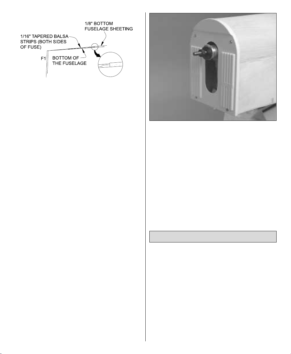
2. Glue tapered strips of leftover 1/16" [1.6mm]
balsa to the bottom of the fuselage sides so that
when in position, the aft edge of the bottom
cowl will be even with the bottom fuselage
sheeting.
3. Glue leftover 1/4" [6.4mm] balsa sticks to the
firewall for the screws that secure the aft edge
of the bottom cowl. Fit the bottom cowl to the
fuse, sanding the edges of the cowl where
necessary for a good fit (this step will be easier
without the engine muffler in the way).
4. Drill 1/16" [1.6mm] holes through the bottom
cowl into the bottom of the fuselage. Remove
the cowl. Enlarge the holes in the cowl only
with a 3/32" [2.4mm] drill. Run the #2 x 3/8"
[9.5mm] screws in and out of the holes a few
times to “cut” threads, then remove the screws
and add a few drops of thin CA to the holes and
allow to fully harden. Mount the bottom cowl to
the fuse with the screws and #2 washers.
5. Cut out the bottom cowl to accommodate the
muffler.
❏
6. Cut out and test fit the molded plastic
front engine cowl to the fuselage. Drill four
1/16" [1.6mm] holes through the cowl into F1.
The bottom two holes should be centered in the
basswood stick on the back of F1. After drilling
the top two holes, glue pieces of leftover 1/8" x
1/4" [3.2 x 6.4mm] basswood to the back of F1
centered over the holes. Drill 1/16" [1.6mm]
holes through the basswood pieces, “cut” the
threads with another #2 x 3/8" [9.5mm] screw,
and harden with CA. Enlarge the holes in the
cowl only with a 3/32" drill, then mount the
front cowl with four #2 x 3/8" [9.5mm] screws
and #2 washers.
In addition to covering, there are still a few
things that need to be done to finish the model
such as the rest of the radio installation and a
few scale details like the pilot, dummy exhaust
pipes and finishing the wing struts. But it’s
easiest to do these things after the model has
been covered.
IMPORTANT: The following instructions
illustrate how the S.E.5a on the kit box top was
covered. It was finished to resemble the S.E.5a
on the cover of the Squadron/Signal
Publications
“S.E.5a In Action”
book. You may
COVER THE MODEL
43
Page 44

follow these instructions exactly, or simply use
them as a guideline while applying your own
covering techniques. However you decide to
finish your S.E.5a, do not forget to install
the “Y” connectors in the wings before
covering them.
❏
1. Remove the engine and any hardware in
the model that would interfere with sanding
and covering.
❏
2. Apply balsa filler where needed, allow to
dry, then final-sand all parts of the model using
progressively finer grits of sandpaper finishing
with 400-grit.
❏
3. Cover the stab up to the lines marked
earlier indicating the sides of the fuselage. First
apply the cream to the bottom, followed by the
olive drab on top. Cover the top and bottom of
the elevators the same way. Don’t forget to cut
the covering from the small vent holes to allow
air to escape while tightening the covering.
Hint: Pre-cut the leading and trailing edges of
the covering on the workbench before ironing it
down. Leave excess material around the tip that
can be used as a “handle” to pull the covering
tight around the tips. After the covering has
been ironed around the tips, trim off the excess
“handle.”
❏
4. Cover the fin, then the rudder. For the
rudder, pieces of dark red, white and sky blue
MonoKote were first scuffed with 600-grit
sandpaper to give it a matt appearance. Then,
the pieces were cut into strips and ironed
together off the model over a piece of glass. A
44
Page 45

1/2" [15mm] overlap is suggested. Lastly, the
red, white and blue were applied to the rudder
as though it were one piece of covering. Use
care not to heat the overlapping seams while
heating the rest of the covering. Otherwise, the
adhesive on the covering will soften, and the
seam may pull apart as the covering tightens.
Don’t forget to leave part of the rudder exposed
for gluing on the tail wheel mount.
❏
5. The fuselage is a little trickier to cover than
it may appear. However, it can be simplified by
covering it in several sections rather than
attempting to do each side in just one or two
pieces. Start with the white band (scuffed with
600-grit sandpaper first), then cover the fuse aft
of the stripe. Cover the rest of the fuselage in
small sections as shown in the photo.
❏
6. Cover the aileron servo hatches.
❏
7. Cover the “corners” and the side of rib R4A
in the wings where the ailerons fit.
❏
8. Cover the bottom of the wings, but do not
yet cover the top of the wings. Before covering
the tops, route a “Y” connector through the
holes in the ribs in both wings. Connect the “Y”
connectors to the aileron servo wires, then
mount the servo hatches to the wing. Secure
the connections between the “Y” connector and
the servo wires with heat shrink tubing, tape or
clips intended for that purpose. Also cut a hole
through the sheeting in the top of the bottom
wing for the Y-connector to exit (the hole in the
top wing for the “Y” connector will be cut later).
Now you may cover
the tops of the wings and
proceed to the
ailerons.
❏
1. Now that the model has been covered, use
epoxy or fuelproof paint to fuelproof areas of
unprotected wood that will be exposed to fuel
or exhaust residue such as the inside of the
engine compartment and partway down into
the radio compartment inside the fuselage
(including the fuselage sides, the back of former
F3 and the front of former F5). Also fuelproof
the grooves in the landing gear blocks if they
are not already sealed by the covering.
❏
2. Cut out the molded plastic head rest
leaving about a 3/16" [5mm] “flange” around
the bottom. Cut out the molded plastic right
and left exhaust pipes. Use coarse sandpaper
to sand the exhaust pipes so they will lie flat.
PAINTING
45
Page 46

❏
3. Glue strips of leftover balsa inside the
exhaust pipes as shown. Sand the balsa strips
even with the bottom edges of the exhaust
pipes so they will lie flat again.
❏
4. Sand all of the plastic parts (head rest,
exhaust pipes, top and bottom cowl) with 400grit sandpaper. Paint the parts as required. On
the model featured on the kit box cover and in
this manual, only one coat of Top Flite
LustreKote olive drab was required for the front
and bottom cowl and the headrest, and one
coat
of flat black was required for the exhaust pipes.
❏
5. After the paint on the exhaust pipes has
fully dried, strip the covering from the fuselage
where necessary so the balsa strips inside the
exhaust pipes will contact bare balsa. (The wing
struts are installed in the photo, but should not
yet be installed on your model.)
❏
6. Glue the exhaust pipes into position. The
head rest will be glued on after finishing the
cockpit later.
❏
7. While geared-up for painting, sand the tail
wheel mount and apply a light coat of wood
stain. Minwax Special Walnut 224 stain was
used on this model. Allow to dry, then spray on
two coats of clear LustreKote, allowing it to dry
and sanding between coats.
❏
1. Cut the covering from the hinge slots in the
tail surfaces and from the pushrod exits in the
rear of the fuselage. Also cut the covering from
the slots in the fuselage for the stab and fin.
GLUE IN THE STAB & FIN
FINAL ASSEMBLY
46
Page 47

❏
2. Prepare to glue the stab into the fuse by
double-checking the stab alignment using the
pin and string technique the same as was done
before the model was covered.
❏
3. Remove the stab from the fuselage. Bolt
the bottom wing to the fuselage. Liberally coat
the exposed balsa on both sides of the stab and
the inside of the fuselage slot where the stab
goes in. Slide the stab into position. Working
quickly, use small paper towel squares or
tissues dampened with denatured alcohol to
wipe off epoxy that has been deposited on the
stab. Use the pin and string to align the stab
with the fuselage and visually align the stab
with the bottom wing. Do not disturb the model
until the epoxy has fully hardened.
❏
4. If you haven’t yet done so, cut a strip of
covering from the bottom of the fuselage where
the bottom of the fin comes into contact.
❏
5. Test fit the fin into the fuselage. Use a
Hobbico Builder’s Triangle or another triangle to
be certain the fin is perpendicular to the stab. If
necessary, when gluing the fin into position in
the next step, use masking tape to pull the stab
to one side or the other to get it vertical.
❏
6. Glue the fin into position on the top and
bottom of the fuselage with 30-minute epoxy.
Use T-pins where necessary to hold the bottom
of the fin to the bottom of the fuselage.
❏
7. Mount the tail wheel to the tail gear mount.
Use 30-minute epoxy to glue the tail gear
mount to the rudder.
47
Page 48

❏
1. If you haven’t yet done so, cut a thin strip
of covering from all of the hinge slots in the
wings and ailerons, stab and elevators and fin
and rudder.
❏ 2. Join one of the ailerons to the
corresponding
wing with the hinges. If the hinges don’t remain
centered, stick a pin through the center of them,
then join the aileron.
3. Remove the pins if used. Adjust the aileron so
there is a small gap between the leading edge
of the aileron and the trailing edge of the
wing–just enough to slip a piece of paper
through or to see light through.
❏
4. Add six drops of thin CA to both sides of
the hinges. Keep a tissue nearby to absorb
excess CA in case any seeps into the hinge gap
or onto the wing.
❏
5. Join the rest of the control surfaces the
same way.
❏
1. Cut the covering from the slots for the strut
retainers in the top and bottom wings.
❏
2. Bend four of the aluminum strut retainers
as shown in the sketch. Use 30-minute epoxy to
permanently glue only the bent strut
retainers into the slots in the center panel in
the top wing. Be certain the holes in the
retainers are in the wing and that the retainers
are installed so the bends are facing inward.
While the epoxy is out, glue the wing dowels
into the bottom wing if you have not done so
already.
FINISH THE WING STRUTS
HINGE THE CONTROL
SURFACES
48
CUT THE COVERING
AWAY FROM THE SLOT
Page 49

❏ 3. Cut the covering from the fuselage 1/8"
[3mm]
inside the openings for the wing struts. Use a
trim iron to iron the edges of the covering
down.
❏
4. Bolt the bottom wing to the fuselage.
Temporarily install the inner wing struts into
the fuselage.
❏ 5. Join the top wing to the inner struts by
fitting
the strut retainers into the tops of the struts.
❏
6. Use the included #33 (1/8"x7" [3.2x180mm])
rubber bands to hold the die-cut 1/8" [3.2mm]
plywood alignment jigs (AJ) to the wings. The
jigs are to be positioned where the outer panels
join the center panels. Make certain all the jigs
are in the same location on the wings. Stabilize
the jigs by clamping the fronts to the rears with
leftover balsa strips. Also note the 1/8"x1/4"
[3x6mm] strips cut from leftover plywood that
have been glued to the sides of the alignment
jigs. This will increase the rigidity of the jigs
while they are holding onto the wings.
❏
7. Raise or lower the struts as necessary until
they are contacting the bottom of the top wing
and the leading and trailing edges of the wing
are centered in the jigs. As the struts were cut
slightly longer than required to allow for
adjustment, it may be necessary to remove
some or all of the struts and trim them to
achieve the adjustment required.
❏
8. View the model from the top. If necessary,
adjust the top wing so it is parallel with the
bottom wing.
❏ 9. Double and triple-check the wing
alignment
as described in the previous three steps. After
confirming that the struts are the correct length
and that the wings align with each other and the
jigs, use a ballpoint pen to mark the inside of
each of the four struts near the top noting its
location (i.e. RF, RR, LF, LR). Make the marks
small, but deep so they can’t get sanded off and
can be seen after the struts have been painted.
❏
10. Rejoin the top wing to the fuselage with
the struts and position the wing jigs. Drill a 1/8"
[3.2mm] hole through one of the struts and the
49
Page 50

strut retainer. Temporarily install a 4-40 x 1/2"
[13mm] screw into the strut and strut retainer.
Hint: When threading in the 4-40 x 1/2" screws,
a Great Planes long-handle 3/32" hex driver ball
wrench (GPMR8002) is indispensable.
❏
11. Confirm that the wing alignment has not
shifted. Adjust if necessary. One at a time drill a
hole through the remaining three struts and
strut retainers, inserting a screw and checking
the wing alignment between each.
❏
12. Mark the struts near the bottom where
they go into the fuselage. When it’s time to paint
the struts, paint them only 1/8" [3mm] below
the line so the epoxy will adhere.
❏
13. Reposition the wing jigs farther out on the
wings–1" [25mm] inboard from the ends of the
ailerons. Without using any glue, insert the
remaining eight strut retainers into the slots in
the wings. Test fit, trim as necessary, then test fit
again and trim the outer struts until they fit the
wing. As you proceed, be certain the wings
remain centered in the wing jigs and that the
leading edges of the wings remain parallel with
each other.
Refer to this photo for the following
four steps.
❏
14. Once all of the outer struts have been
trimmed to the correct length, one at a time,
remove the outer struts and use a ballpoint pen
to mark them the same way you did the inner
struts (i.e. RF, RR, LF, LR). Remove the top wing
and take all the struts off.
❏
15. Drill a 1/8" [3.2mm] hole 5/16" [8mm] from
both ends of the outer struts. Enlarge only the
inner hole of all the struts with a 5/32" [4mm]
drill. Hint: Slip a strut retainer into the slot in
the strut to stop the drill from going all the way
through and enlarging the hole in the other
side.
❏ 16. Sand all the struts smooth with
progressively
finer grits of sandpaper.
❏
17. Insert a 4-40 blind nut into one of the
struts. Slip a piece of thin plywood into the slot
in the strut, then use a hammer to lightly tap the
blind nut all the way into the strut. Add medium
CA all the way around the flange of the blind
nut to permanently hold it in. Insert blind nuts
into the holes in the rest of the struts the
same way.
❏
18. Apply wood stain to the struts. Allow to
dry, then apply a clear coat of fuelproof paint.
❏
19. After the paint on the struts has dried, mix
up a batch of 30-minute epoxy and glue the
inner struts into the fuselage. Working quickly
before the epoxy hardens, join the top wing to
the struts and bolt them on with the 4-40 x 1/2"
[13mm] bolts. Reattach the wing jigs to the
inner locations to the wings. Align the wings.
Check the wing alignment frequently as the
epoxy hardens.
❏
20. The same as you did before, install the
strut retainers in the wings and fit the outer
struts. Move the wing jigs out on the wings and
check the alignment. Mark the bottom hole in
all the outer struts onto the bottom strut
retainers.
❏
21. Remove struts. Remove the bottom strut
retainers, marking each one so they may be
reinstalled in the same slot they came from
exactly the same way they came out.
50
Page 51

❏
22. Drill 1/8" [3.2mm] holes through the
bottom strut retainers at the marks you made.
Fill the strut retainer slots in the bottom wing
with 30-minute epoxy, then working quickly,
insert the strut retainers, wipe away excess
epoxy and mount the struts to the top and
bottom strut retainers with the screws. Still
working quickly before the 30-minute epoxy
hardens, position the wing jigs, align the wings
as necessary and do not disturb the plane until
the epoxy has fully hardened.
❏
23. Place the model upside-down on your
workbench. Mark, drill and glue the strut
retainers into the top wing the same as you did
the bottom wing. Leave the model upside-down
while the epoxy hardens so it does not run
down into the struts.
❏
1. Thread a nylon clevis about twenty full
turns onto a 36" [915mm] wire pushrod, then
slip a silicone retainer over the clevis. Connect
the clevis to the outer hole of a nylon control
horn. Prepare two more pushrods the same
way.
❏
2. Slide the pushrods into the guide tubes
from the rear of the fuselage. The elevator
pushrods go in the top guide tubes (nearest the
elevator) and the rudder pushrod goes in the
guide tube opposite the previously installed
throttle servo.
❏
3. Drill 3/32" [2.4mm] holes through the
elevators and rudder for mounting the control
horns. Mount the control horns with 2-56 x 5/8"
[16mm] screws and the nylon mounting plates
(it may be necessary to make a slight bend in
the elevator pushrods to get them to rest on the
elevators where required).
❏
4. Fit the elevator and rudder servos into the
servo tray, but do not drill holes and screw
them in yet. Note: As shown on the plan and in
this manual, both elevator pushrods are
connected to one elevator servo. However, as
explained near the beginning of the manual,
two servos could be used for the elevators.
❏
5. Make a 90° bend in one of the elevator
pushrods to connect it to the elevator servo
arm. Hint: Disconnect the pushrod from the
elevator and rotate the pushrod 90-degrees.
Make the bend to the side, then rotate the
pushrod back into position so the bend is
downward (toward the bottom of the fuselage).
Connect the pushrod to the servo arm and the
elevator. Adjust the clevis on the end of the
FINISH THE RADIO
INSTALLATION
51
Page 52
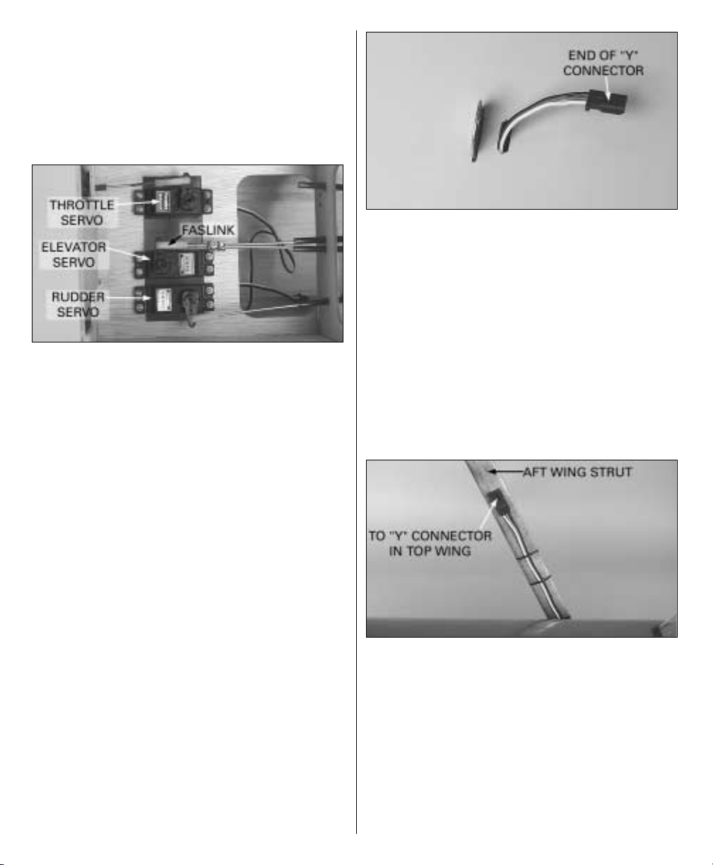
pushrod so the elevator is centered when the
servo arm is centered.
Refer to this photo for the following
three steps.
❏
6. Cut the other elevator pushrod about 1"
short of the servo arm. Slip two 5/32" [4mm]
wheel collars with two 6-32 x 1/4" [6.4mm]
screws over the pushrods. Connect the pushrod
already bent to the servo arm with a FasLink.
Drill 1/16" [1.6mm] holes into the servo tray for
the servo mounting screws, run the screws in
and out a few times and add a few drops of thin
CA to the holes. Allow the CA to fully harden,
then mount the elevator servo with the screws.
❏
7. With the servo arm and the elevator that is
connected to the servo arm centered, center the
other elevator, then tighten the screw on one of
the wheel collars to lock the pushrods together.
Remove the screw from the other wheel collar,
add a drop of threadlocker to the threads, then
insert the screw into the wheel collar and
tighten. Remove the other screw, add
threadlocker,
reinsert and tighten.
❏
8. Connect the rudder pushrod to the rudder
servo by making a 90° bend in the pushrod and
fastening it to the servo arm with a FasLink.
Mount the rudder servo to the servo tray the
same as was done for the elevator servo.
❏
9. Cut a small hole in the bottom of the top
wing near one of the aft strut retainers. Use a
small piece of wire with a hook bent on the end
to “fish out” the end of the “Y” connector
previously installed in the wing.
❏
10. Cut a small hole through the fuselage
near the bottom of the aft wing strut that is on
the same side as the hole just cut in the wing.
Route the end of a “Y” connector that connects
to a servo out of the hole for connecting to the
servo wire coming from the wing. Suggestion:
Roughen one side of the plug so glue will
adhere, then use epoxy to glue the plug to the
inside of the strut. Secure the servo wire to the
strut with tape. This will make it easy to connect
the servo wire coming out of the wing.
52
Page 53

❏
11. Mount the battery pack. It is suggested
that the battery pack be mounted as far forward
as practically possible to reduce or eliminate
the amount of lead ballast that may be required
in the nose. With the battery mounted where
shown, our prototype required approximately
8 oz. of weight in the nose. Make a mounting
plate from leftover plywood and balsa. Secure
the battery to the plate (with R/C foam rubber in
between) with Velcro, then securely glue the
balsa rails on the bottom of the plate to the
bottom of the fuselage behind the firewall (the
fuel tank must be removed to do this).
Refer to this photo for the following
three steps.
❏
12. Mount the receiver. For this model a
removable mounting plate was made from
leftover plywood and screwed to leftover hard
balsa rails glued to the fuselage sides. The
receiver was mounted to the plywood plate
(with R/C foam in between) with rubber bands.
❏
13. Connect the servo wires and on/off switch
to the receiver and connect the battery to the
on/off switch. Connect the end of the “Y”
connector for the ailerons to the aileron plug in
the receiver (the remaining end of the “Y”
connector will be connected to the other “Y”
connector coming from the ailerons in the
bottom wing). Mount the on/off switch to the
side of the fuselage. For easy battery
monitoring and quick-charging, a Great Planes
Switch & Charge Jack Mounting Set
(GPMM1000)
was used on this model.
❏ 14. Route the antenna through the open
guide
tube that doesn’t have any pushrods.
❏
1. Assemble and test fit the pilot. A William’s
Brother’s 1/4-Scale WWI Pilot (WBRQ2625) was
used in this model. Even though this S.E.5a is
closer to 1/5-scale, upon studying and test
fitting various sizes of pilots, it was decided that
the 1/4-scale pilot fits best and appears to be
most scale-like. Placing the pilot on a 2" x 2" [50
x 50mm] balsa block (not included) positions
him perfectly at the correct height.
❏
2. Paint the pilot and cockpit. Optional: The
cockpit can be “dressed-up” with Fourmost
Products #FOR 114 Regular Cockpit Coaming
(FORQ2014). Cut it to the length required, fit it
over the edges of the opening and glue it into
position with thin CA.
❏
3. Securely glue the pilot (and balsa block if
used) into position.
❏
4. Mount the headrest to the top of the
fuselage behind the pilot. A simple and secure
method is to use double-sided tape, but the
headrest could also be glued into position
FINISH THE COCKPIT
53
Page 54

similar to the way the exhaust pipes were glued
into position with balsa sticks.
❏ 5. Cut out the molded clear plastic
windscreen.
Paint the base black. Position the windscreen on
the fuselage, then mark its outline directly onto
the fuselage with a ballpoint pen. Cut a 1/16"
[1.6mm] strip of covering from the fuselage
along the line.
❏
6. Position the windscreen on the fuselage so
it conceals the removed strip of covering. Glue
the windscreen into place with thin or medium
CA. Use the CA sparingly so as not to fog the
plastic.
A wing-mounted machine gun is not supplied
with this kit, but the following instructions show
how to make one from a William’s Brother’s
#16100 2" (1/6-scale) Lewis Aircraft Machine
Gun kit (WBRQ3561) and a few other various
hobby materials.
Refer to this photo while making the
machine gun and mount.
❏
1. Assemble the machine gun per the
instructions that came with it.
❏
2. Make the sliding mount from a sheet of
plastic or thin plywood (the cross-section is the
shape of an “I” beam). The forward mount
was made from a 3/16" wood dowel (though
further study of the photos shows that the
forward mount should actually be square).
❏
3. Notch the aft end of the forward mount and
connect it to the sliding mount with a piece of
brass tubing. Carve the mounting pods from
balsa or basswood and glue them to the
forward mount.
❏
4. Paint the machine gun and mount, then
mount to the top of the wing.
MOUNT THE MACHINE GUN
54
Page 55

1. Use scissors or a sharp hobby knife to cut the
decals from the sheet.
2. Be certain the model is clean and free from
oily fingerprints and dust. Prepare a dishpan or
small bucket with a mixture of liquid dish soap
and warm water–about one teaspoon of soap
per gallon of water. Submerse the decal in the
soap and water and peel off the paper backing.
Note: Even though the decals have a “stickyback” and are not the water transfer type,
submersing them in soap & water allows
accurate positioning and reduces air bubbles
underneath.
3. Position the decal on the model where
desired. Holding the decal down, use a paper
towel to wipe most of the water away.
4. Use a piece of soft balsa or something similar
to squeegee remaining water from under the
decal. Apply the rest of the decals the same
way.
❏
1. Turn on the transmitter and receiver and
center the trims. If necessary, remove the servo
arms from the servos and reposition them so
they are centered. Reinstall the screws that hold
on the servo arms.
❏
2. With the transmitter and receiver still on,
check all the control surfaces to see if they are
centered. If necessary, adjust the clevises on the
pushrods to center the control surfaces.
❏
3. Make certain that the control surfaces and
the carburetor respond in the correct direction
as shown in the diagram. If any of the controls
respond in the wrong direction, use the servo
reversing in the transmitter to reverse the
servos connected to those controls. Be certain
the control surfaces have remained centered.
Adjust if necessary.
Use a Great Planes AccuThrow™(or a ruler) to
accurately measure and set the control throw of
each control surface as indicated in the chart
that follows.
SET THE CONTROL THROWS
CHECK THE CONTROL
DIRECTIONS
GET THE MODEL READY
TO FLY
APPLY THE DECALS
55
Page 56

At this stage the model should be in ready-to-fly
condition with all of the systems in place
including the engine, landing gear, covering
and paint, and the radio system.
❏
1. Use a felt-tip pen or 1/8" [3mm]-wide tape
to accurately mark the C.G. across the center
panel on the bottom of the top wing 5-1/2"
[140mm] back from the leading edge.
❏
2. With the wing attached to the fuselage, all
parts of the model installed (ready to fly) and an
This is where your model should balance for
the first flights. Later, you may wish to
experiment by shifting the C.G. up to 1/4"
[6mm] forward or 1/4" [6mm] back to change
the flying characteristics. Moving the C.G.
forward may improve the smoothness and
stability, but the model may then require
more speed for takeoff and make it more
difficult to slow for landing. Moving the C.G.
aft makes the model more maneuverable, but
could also cause it to become too difficult to
control. In any case, start at the
recommended balance point and do not
at any time balance the model outside the
specified range.
More than any other factor, the C.G. (balance
point) can have the greatest effect on how a
model flies, and may determine whether or
not your first flight will be successful. If you
value this model and wish to enjoy it for
many flights, DO NOT OVERLOOK THIS
IMPORTANT PROCEDURE. A model that is
not properly balanced will be unstable and
possibly unflyable.
BALANCE THE MODEL (C.G.)
IMPORTANT:The S.E.5a has been
extensively
flown and tested to arrive at the throws at
which it flies best. Flying your model at these
throws will provide you with the greatest
chance for successful first flights. If, after you
have become accustomed to the way the
S.E.5a flies, you would like to change the
throws to suit your taste, that is fine.
However, too much control throw could make
the model difficult to control, so remember,
“more is not always better.”
These are the recommended control
surface throws:
High Rate Low Rate
ELEVATOR: 1-1/2" [38mm] up 3/4" [19mm] up
1-1/2" [38mm] down 3/4" [19mm] down
RUDDER: 1-1/2" [38mm] right 1" [25mm] right
1-1/2" [38mm] left 1" [25mm] left
AILERONS: 1-1/2" [38mm] up 1" [25mm] up
1-1/2" [38mm] down 1" [25mm] down
56
Page 57

empty fuel tank, have an assistant lift the model
at the balance point you marked on the bottom
of the top wing. Hint: Instead lifting the model
with his finger tips, have your assistant use the
eraser end of a pencil held in each hand to lift
the model (be certain the erasers are positioned
on the line near the ends of the center panel
under the ribs inside). This will improve the
accuracy of the C.G. procedure.
❏
3. While your assistant is holding the model
at the balance point, view the model from the
side. (If viewing the model from the front as you
would be if doing this procedure by yourself,
detecting whether or not the fuselage is level
would be difficult. Viewing the model from the
side provides a much better perspective.) If the
fuselage is not level as shown in the photo, the
C.G. must be corrected. If the tail is low, the
model is “tail heavy” and the battery pack
and/or receiver must be shifted forward or
weight must be added to the nose to balance. If
the nose is low, the model is “nose heavy” and
the battery pack and/or receiver must be shifted
aft or weight must be added to the tail to
balance. If adding additional weight, nose
weight may be easily added by using a “spinner
weight” (GPMQ4645 for the 1 oz. [28g] weight,
or GPMQ4646 for the 2 oz. [57g] weight). If
spinner weight is not practical or is not enough,
use Great Planes (GPMQ4485) “stick-on” lead. A
good place to add stick-on nose weight is to the
firewall or fuselage sides (don’t attach weight to
the cowl–it is not intended to support weight).
Begin by placing incrementally increasing
amounts of weight on the top of the fuse over
the firewall until the model balances. Once you
have determined the amount of weight
required, it can be permanently attached. If
required, tail weight may be added by cutting
open the bottom of the fuse and gluing it
permanently inside.
Note: Do not rely upon the adhesive on the
back of the lead weight to permanently hold it
in place. Over time, fuel and exhaust residue
may soften the adhesive and cause the weight
to fall off. Use #2 sheet metal screws, RTV
silicone or epoxy to permanently hold the
weight in place.
❏
4. IMPORTANT: If you found it necessary to
add any weight, recheck the C.G. after the
weight has been installed.
❏
1. With the wings level, have an assistant help
you lift the model by the engine propeller shaft
and the bottom of the fuse under the TE of the
fin. Do this several times.
❏
2. If one wing always drops when you lift the
model, it means that side is heavy. Balance the
airplane by adding weight to the other wing tip.
An airplane that has been laterally
balanced will track better in loops and
other maneuvers.
No matter if you fly at an AMA sanctioned R/C
club site or if you fly somewhere on your own,
you should always have your name, address,
telephone number and AMA number on or
inside your model. It is required at all AMA R/C
club flying sites and AMA sanctioned flying
events. Fill out the identification tag on the
decal sheet and place it on or inside your
model.
Follow the battery charging instructions that
came with your radio control system to charge
the batteries. You should always charge your
CHARGE THE BATTERIES
IDENTIFY YOUR MODEL
PREFLIGHT
BALANCE THE MODEL
LATERALLY
57
Page 58

transmitter and receiver batteries the night
before you go flying, and at other times as
recommended by the radio manufacturer.
Note Checking the condition of your receiver
battery pack is highly recommended. All
battery packs, whether it’s a trusty pack you’ve
just taken out of another model, or a new
battery pack you just purchased, should be
cycled, noting the discharge capacity.
Oftentimes, a weak battery pack can be
identified (and a valuable model saved!) by
comparing its actual capacity to its rated
capacity. Refer to the instructions and
recommendations that come with your cycler. If
you don’t own a battery cycler, perhaps you can
have a friend cycle your pack and note the
capacity for you.
Carefully balance your propeller and spare
propellers before you fly. An unbalanced prop
can be the single most significant cause of
vibration that can damage your model. Not only
will engine mounting screws and bolts loosen,
possibly with disastrous effect, but vibration
may also damage your radio receiver and
battery. Vibration can also cause your fuel to
foam, which will, in turn, cause your engine to
run hot or quit.
We use a Top Flite Precision Magnetic Prop
Balancer™ (TOPQ5700) in the workshop and
keep a Great Planes Fingertip Prop Balancer
(GPMQ5000) in our flight box.
If the engine is new, follow the engine
manufacturer’s instructions to break-in
the engine. After break-in, confirm that the
engine idles reliably, transitions smoothly and
rapidly to full power and maintains full
power–indefinitely. After you run the engine on
the model, inspect the model closely to make
sure all screws remained tight, the hinges are
secure, the prop is secure and all pushrods and
connectors are secure.
Ground check the operational range of your
radio before the first flight of the day. With the
transmitter antenna collapsed and the receiver
and transmitter on, you should be able to walk
at least 100 feet [30m] away from the model and
still have control. Have an assistant stand by
your model and, while you work the controls,
tell you what the control surfaces are doing.
Repeat this test with the engine running at
various speeds with an assistant holding the
model, using hand signals to show you what is
happening. If the control surfaces do not
respond correctly, do not fly! Find and correct
the problem first. Look for loose servo
connections
or broken wires, corroded wires on old servo
connectors, poor solder joints in your battery
pack or a defective cell, or a damaged receiver
crystal from a previous crash.
Failure to follow these safety
precautions
may result in severe injury to yourself
and others.
ENGINE SAFETY
PRECAUTIONS
RANGE CHECK
GROUND CHECK
BALANCE THE PROPELLER
58
Page 59

Keep all engine fuel in a safe place, away from
high heat, sparks or flames, as fuel is very
flammable. Do not smoke near the engine or
fuel; and remember that engine exhaust gives
off a great deal of deadly carbon monoxide.
Therefore, do not run the engine in a closed
room or garage.
Get help from an experienced pilot when
learning to operate engines.
Use safety glasses when starting or running
engines.
Do not run the engine in an area of loose gravel
or sand; the propeller may throw such material
in your face or eyes.
Keep your face and body as well as all
spectators away from the plane of rotation of
the propeller as you start and run the engine.
Keep these items away from the prop: loose
clothing, shirt sleeves, ties, scarfs, long hair or
loose objects such as pencils or screwdrivers
that may fall out of shirt or jacket pockets into
the prop.
Use a “chicken stick” or electric starter to start
the engine. Do not use your fingers to flip the
propeller. Make certain the glow plug clip or
connector is secure so that it will not pop off or
otherwise get into the running propeller.
Make all engine adjustments from behind the
rotating propeller.
The engine gets hot! Do not touch it during or
right after operation. Make sure fuel lines are in
good condition so fuel will not leak onto a hot
engine, causing a fire.
To stop a glow engine, cut off the fuel supply by
closing off the fuel line or following the engine
manufacturer’s recommendations. Do not use
hands, fingers or any other body part to try to
stop the engine. To stop a gasoline powered
engine an on/off switch should be connected to
the engine coil. Do not throw anything into the
propeller of a running engine.
Read and abide by the following Academy of
Model Aeronautics Official Safety Code:
GENERAL
1. I will not fly my model aircraft in sanctioned
events, air shows, or model flying
demonstrations until it has been proven to be
airworthy by having been previously
successfully flight tested.
2. I will not fly my model aircraft higher than
approximately 400 feet within 3 miles of an
airport without notifying the airport operator. I
will give right of way to, and avoid flying in the
proximity of full scale aircraft. Where necessary
an observer shall be used to supervise flying to
avoid having models fly in the proximity of full
scale aircraft.
3. Where established, I will abide by the safety
rules for the flying site I use, and I will not
willfully and deliberately fly my models in a
careless, reckless and/or dangerous manner.
7. I will not fly my model unless it is identified
with my name and address or AMA number, on
or in the model.
9. I will not operate models with pyrotechnics
(any device that explodes, burns, or propels a
projectile of any kind).
RADIO CONTROL
1. I will have completed a successful radio
equipment ground check before the first flight
of a new or repaired model.
AMA SAFETY CODE (excerpt)
59
Page 60

2. I will not fly my model aircraft in the presence
of spectators until I become a qualified flier,
unless assisted by an experienced helper.
3. I will perform my initial turn after takeoff
away from the pit or spectator areas, and I will
not thereafter fly over pit or spectator areas,
unless beyond my control.
4. I will operate my model using only radio
control frequencies currently allowed by the
Federal Communications Commission.
Since the S.E.5a qualifies as a “giant
scale” model and is therefore eligible to
fly in IMAA events, we’ve printed excerpts
from the IMAA Safety Code which
follows:
Definition
For the purpose of the following IMAA Safety
Code, the term “Giant Scale” shall refer to radio
controlled model aircraft, either scale or nonscale, which have a wingspan of 80 inches or
more for monoplanes and 60 inches or more for
multi-winged model aircraft and have a ramp
weight (fueled and ready to fly) of 55 lbs.
or less.
Section 1.0: SAFETY STANDARD
1.1 Adherence to Code: This safety code is to be
strictly followed
1.2 The most current AMA Safety Code in effect
is to be observed. However, the competition
sections of the code may be disregarded.
Section 3.0: Safety Check
3.4 Flight Testing: All Giant Scale R/C aircraft are
to have been flight tested and flight trimmed
with a minimum of six flights before the model
is allowed to fly at an IMAA Sanctioned event.
3.5 Proof of Flight: The completing and signing
of the Declaration section of the Safety
Inspection form by the pilot (or owner) shall
document as fact that each aircraft has been
successfully flight-tested and proven airworthy
prior to an IMAA event.
Section 6.0: Radio Requirements
6.1 All transmitters must be FCC type certified.
6.2 FCC Technician or higher-class license
required for 6 meter band operation only.
❏
1. Fuelproof all areas exposed to fuel or
exhaust residue such as the engine
compartment, radio compartment inside
the fuselage and the fuel tank
compartment.
❏ 2. Check the C.G. according to the
measurements provided in the manual.
During the last few moments of preparation
your mind may be elsewhere anticipating the
excitement of the first flight. Because of this,
you may be more likely to overlook certain
checks and procedures that should be
performed before the model is flown. To help
avoid this, a checklist is provided to make
sure these important areas are not
overlooked. Many are covered in the
instruction manual, so where appropriate,
refer to the manual for complete instructions.
Be sure to check the items off as they are
completed (that’s why it’s called a
check list!
)
CHECK LIST
IMAA SAFETY CODE
(excerpt)
60
Page 61

❏
3. Be certain the battery and receiver are
securely mounted in the fuse. Simply
stuffing them into place with foam
rubber is not sufficient.
❏
4. Extend the receiver antenna and make
sure it has a strain relief inside the
fuselage to keep tension off the solder
joint inside the receiver.
❏
5. Balance the model
laterally
as explained
in the instructions.
❏
6. Use thread locking compound to secure
critical fasteners such as the set screws
in the wheel collars, screws that hold the
carburetor arm (if applicable), screw-lock
pushrod connectors, etc.
❏
7. Add a drop of oil to the axles so the
wheels will turn freely.
❏
8. Make sure all hinges are securely glued
in place.
❏
9. Reinforce holes for wood screws with
thin CA where appropriate (servo
mounting screws, cowl mounting
screws, etc.).
❏
10. Confirm that all controls operate in the
correct direction and the throws are set
up according to the manual.
❏
11. Make sure there are silicone retainers on
all the clevises and that all servo arms
are secured to the servos with the screws
included with your radio.
❏
12. Secure connections between servo wires
and Y-connectors or servo extensions,
and the connection between your battery
pack and the on/off switch with vinyl
tape, heat shrink tubing or special clips
suitable for that purpose.
❏
13. Make sure any servo extension cords you
may have used do not interfere with
other systems (servo arms, pushrods,
etc.).
❏
14. Secure the pressure tap (if used) to the
muffler with high temp RTV silicone,
thread locking compound or J.B. Weld.
❏
15. Make sure the fuel lines are connected
and are not kinked.
❏
16. Use an incidence meter to check the wing
for twists and attempt to correct before
flying.
❏
17. Balance your propeller (and spare
propellers).
❏
18. Tighten the propeller nut and spinner.
❏ 19. Place your name, address, AMA number
and telephone number on or inside your
model.
❏
20. Cycle the receiver battery pack (if
necessary) and make sure it is fully
charged.
❏
21. If you wish to photograph the model, do
so before the first flight.
❏
22. Range check your radio when you get to
the flying field.
The Dynaflite S.E.5a is a great-flying model that
flies smoothly and predictably. The S.E.5a does
not, however, possess the self-recovery
characteristics of a primary R/C trainer and
should be flown only by experienced R/C pilots.
A fully cowled engine may run at a higher
temperature than an un-cowled engine. For this
reason, the fuel mixture should be richened so
the engine runs at about 200 rpm below peak
speed. By running the engine slightly rich, you
will help prevent dead-stick landings caused by
overheating.
FUEL MIXTURE ADJUSTMENTS
FLYING
61
Page 62
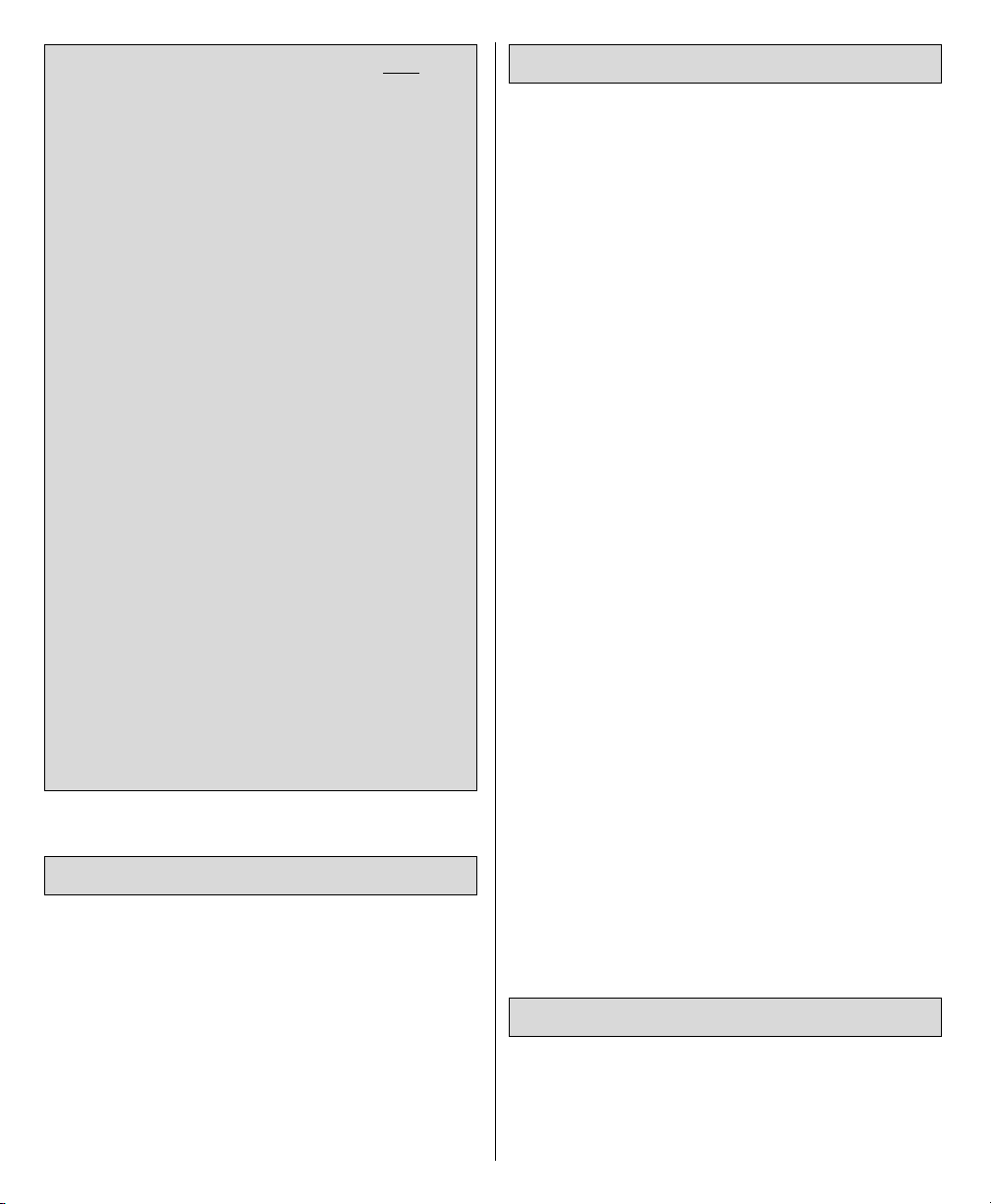
Mount the bottom wing to the fuselage with the
1/4-20 x 2" [50mm] nylon wing bolts and 1/4"
[6mm] washers to hold the aft landing gear wire
to the wing. Be certain the #2 x 1/2" [13mm]
screws that hold the landing gear straps over
the forward landing gear wire are tight. Mount
the top wing with the struts and screws. A small
drop of non-permanent threadlocker on the
threads of the screws for the wing struts is
recommended.
The Dynaflite S.E.5a handles well on the
ground–similar to most tail draggers such as a
Mustang and even easier than some tail
draggers such as a Cub. The S.E.5a does,
however, weathervane easily in crosswinds so
be sure to use the high-rate for the rudder.
Before taking off, see how the model handles
on the ground by doing a few practice runs at
low speeds on the runway. Hold “up” elevator
to keep the tail wheel on the ground. If
necessary, adjust the rudder so the model will
roll straight down the runway. If you need to
gather your thoughts before the maiden flight,
shut the engine down and bring the model back
into the pits. Top off the fuel, then check all
fasteners and control linkages for peace of
mind.
Remember to takeoff into the wind. When
ready, point the model straight down the
runway, hold a bit of up elevator to keep the tail
on the ground to maintain tail wheel steering,
then gradually advance the throttle. As the
model gains speed decrease up elevator
allowing the tail to come off the ground. One of
the most important things to remember with a
tail dragger is to always be ready to apply right
rudder to counteract engine torque. Gain as
much speed as your runway and flying site will
practically allow before gently applying up
elevator, lifting the model into the air. At this
moment it is possible that additional right
rudder will be required to counteract engine
torque. Be smooth on the elevator stick,
allowing the model to establish a gentle climb
to a safe altitude before turning into the traffic
pattern established at your field.
In its time, the British Royal Aircraft Factory
S.E.5a was a groundbreaking aircraft with
exceptional climb rates and dog-fighting
abilities. Powered with the recommended
FLIGHT
TAKEOFF
FIELD ASSEMBLY
CAUTION (THIS APPLIES TO ALL
R/C
AIRPLANES): If, while flying, you notice an
alarming or unusual sound such as a lowpitched “buzz,” this may indicate control
surface
flutter
. Flutter occurs when a control
surface (such as an aileron or elevator) or a
flying surface (such as a wing or stab) rapidly
vibrates up and down (thus causing the
noise). In extreme cases, if not detected
immediately, flutter can actually cause the
control surface to detach or the flying surface
to fail, thus causing loss of control followed
by an impending crash. The best thing to do
when flutter is detected is to slow the model
immediately by reducing power, then land as
soon and safely as possible. Identify which
surface fluttered (so the problem may be
resolved) by checking all the servo grommets
for deterioration or signs of vibration. Make
certain all pushrod linkages are secure and
free of play. If it fluttered once, under similar
circumstances it will probably flutter again
unless the problem is fixed. Some things
which can cause flutter are; Excessive hinge
gap; Not mounting control horns solidly;
Poor fit of clevis pin in horn; Side-play of wire
pushrods caused by large bends; Excessive
free play in servo gears; Insecure servo
mounting; and one of the most prevalent
causes of flutter; Flying an over-powered
model at excessive speeds.
62
Page 63

engines, the Dynaflite S.E.5a is similarly nimble
with a good climb rate and the ability to
perform many classic dog-fighting maneuvers
including loops, rolls, spins, stall turns,
Immelman turns, etc.
When you’re ready to fly, it would be a good
idea to have an assistant on the flight line with
you for reassurance and to keep an eye on
other air traffic. Tell him to remind you to
throttle back once the plane gets to a
comfortable altitude. While full throttle is
usually desirable for takeoff, most models fly
more smoothly at reduced speeds. Take it easy
with the S.E.5a for the first few flights,
gradually getting acquainted with it as you gain
confidence. Adjust the trims to maintain
straight and level flight. After flying around for
a while, and while still at a safe altitude with
plenty of fuel, practice slow flight and execute
practice landing approaches by reducing the
throttle to see how the model handles at slower
speeds. Add power to see how she climbs as
well. Continue to fly around, executing various
maneuvers and making mental notes (or having
your assistant write them down) of what trim or
C.G. changes may be required to fine tune the
model so it flies the way you like. Mind your
fuel level, but use this first flight to become
familiar with your model before landing.
Unless experienced and confident in your
ability to control a model in crosswinds, it is
strongly recommend that your first flights with
the S.E.5a are in calm conditions or when the
winds are parallel with the runway. Without
crosswinds, the S.E.5a lands beautifully–just
the same as any other model. However, in a
crosswind the model must be “crosscontrolled” so that its heading and trajectory
are parallel with the runway. For example, if
there were a crosswind coming from the left,
right rudder and left aileron would have to be
applied to counter the crosswind and keep the
model heading straight down the runway. If the
wheels are not going straight when the model
touches down it may ground loop. If you’re not
comfortable doing these “slip” landings,
practice in non-windy conditions or have an
experienced pilot assist you.
One final note about flying your model. Have a
goal or flight plan in mind for every flight. This
can be learning a new maneuver(s), improving
a maneuver(s) you already know, or learning
how the model behaves in certain conditions
(such as on high or low rates). This is not
necessarily to improve your skills
(though it is
never a bad idea!)
, but more importantly so you
do not surprise yourself by impulsively
attempting a maneuver and suddenly finding
that you’ve run out of time, altitude or airspeed.
Every maneuver should be deliberate, not
impulsive. For example, if you’re going to do a
loop, check your altitude, mind the wind
direction (anticipating rudder corrections that
will be required to maintain heading),
remember to throttle back at the top, and make
certain you are on the desired rates (high/low
rates). A flight plan greatly reduces the chances
of crashing your model just because of poor
planning and impulsive moves. Remember to
think.
Have a ball! But always stay in control and
fly in a safe manner.
GOOD LUCK AND GREAT FLYING
LANDING
63
Page 64

BUILDING NOTES
Kit Purchased Date: _______________________
Where Purchased:_________________________
Date Construction Started: _________________
Date Construction Finished: ________________
Finished Weight: __________________________
Date of First Flight: ________________________
FLIGHT LOG
 Loading...