

Page 1
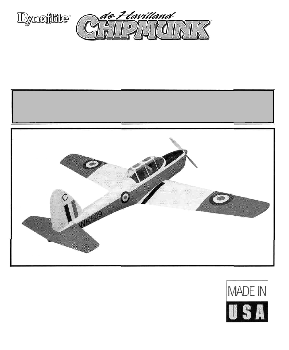
• BUILDS QUICKLY
• REALISTIC FUN SCALE® MODEL
• HUGE, 89" WINGSPAN (IMAA Legal)
READ THROUGH THIS INSTRUCTION MANUAL FIRST. IT CONTAINS
IMPORTANT INSTRUCTIONS AND WARNINGS CONCERNING THE ASSEMBLY
AND USE OF THIS MODEL.
Instruction Manual
Dynaflite guarantees this kit to be free from defects in both material and workmanship at the
date of purchase. This warranty does not cover any component parts damaged by use or
modification. In no case shall Dynaflite's liability exceed the original cost of the purchased kit.
Further, Dynaflite reserves the right to change or modify this warranty without notice. In that
Dynaflite has no control over the final assembly or material used for final assembly, no liability
shall be assumed nor accepted for any damage resulting from the use by the user of the final
user-assembled product. By the act of using the user-assembled product, the user accepts all
resulting liability. If the buyer is not prepared to accept the liability associated with the use of
this product, return this kit immediately in new and unused condition to the place of purchase.
CHPGP03 Printed in USA V1.0 Entire Contents © Copyright 2000
WARRANTY
Page 2
Introduction................................................2
Precautions ................................................2
Preparations
..............................................3
Required Accessories..........................................3
Optional
Suggested
Building
Adhesives
Accessories
Supplies
Notes
..........................................4
............................................4
....................................................5
............................................................5
Common Abbreviations......................................6
Types
of
Wood
....................................................6
Inch/Metric Ruler..................................................6
Die-Cut Patterns............................................7 & 8
Build the Stabilizer & Elevators
................9
Build the Vertical Fin & Rudder................10
Build the
Build
Build the Wing
Join the Wing
Build the Ailerons
Fuselage
the
Bulkheads
....................................12
..........................................12
..........................................19
Panels
................................23
....................................26
Build the Flaps..........................................27
Mount
Finish the
the Wing
Fuselage
to
the Fuselage
..............28
..................................29
Final Assembly..........................................33
Finishing
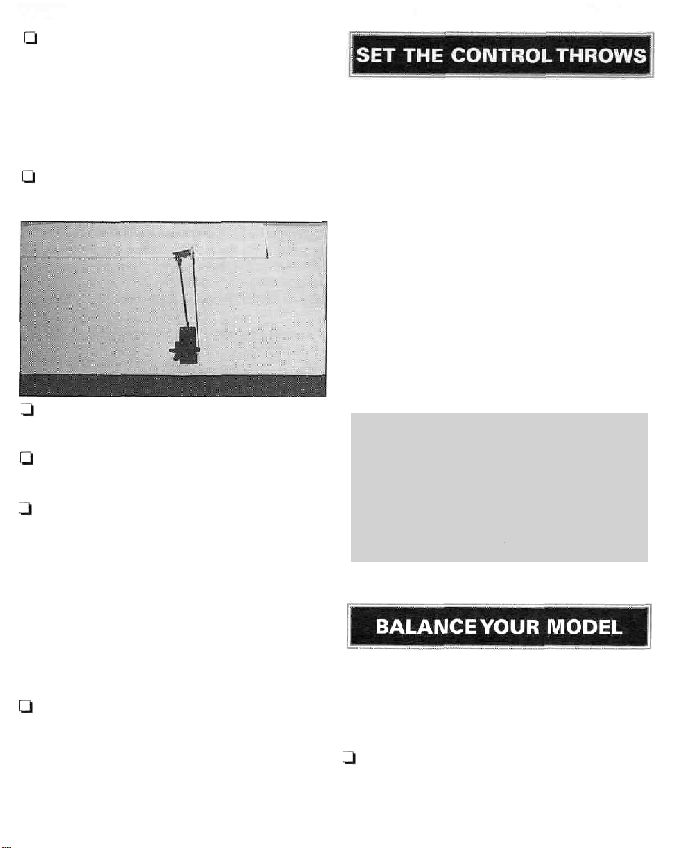
Set the Control Throws
Balance
Balance the Model Laterally
..................................................35
............................36
Your
Model
..................................36
....................37
Preflight....................................................37
At
Home
............................................................37
At the Flying Site ..............................................38
Engine Safety Precautions
AMA
Safety Code (excerpt)
......................38
......................39
Flying ........................................................39
Find a Safe
Place
to
Fly
....................................39
Takeoff................................................................40
Flight ..................................................................40
Landing
..............................................................40
At Dynaflite we take pride in offering kits that
are simple and straightforward to build and
provide value for your modeling dollar.
Because of the size and cost of this model we
assume you have built several models and have
a general working knowledge of modeling and
its terms. If you HAVE NOT built and flown
several kits, do yourself a favor - back up and
get some experience before beginning this kit.
1.You must build the plane according to the
plan and instructions. Do not alter or modify
the model, as doing so may result in an unsafe
or unflyable model. In a few cases the plan
and instructions may differ slightly from
the photos. In those instances the plan
and written instructions are correct.
2. You must take time to build straight, true
and strong.
3. You must use a proper R/C radio that is in
first class condition, the correct size of engine
and correct components (fuel tank, wheels,
etc.) throughout your building process.
4. You must properly install all R/C and other
components so that the model operates
properly on the ground and in the air.
5. You must test the operation of the model
before every flight to insure that all equipment
is operating and you must make certain that the
model has remained structurally sound.
Congratulations on your choice of this kit for
your next project. The Chipmunk is a Fun Scale®
model of a true classic aircraft. It has the
presence that only a big model can carry off.
6. If you are not already an experienced R/C
pilot, you must fly the model only with the
help of a competent, experienced R/C pilot.
Remember: Take your time and follow
instructions to end up with a well-built
model that is straight and true.
2
Page 3
Your Chipmunk is not a toy, but a sophisticated
working model that functions very much like an
actual airplane. Because of its realistic
performance, if you do not assemble and
operate your Chipmunk correctly, you could
possibly injure yourself or spectators and
damage property.
If you are calling for replacement parts,
please look up the part numbers and the
kit identification number (stamped on the
end of the carton) and have them ready
when you call.
To make your R/C modeling experience
totally enjoyable, get assistance with
assembly and your first flights from an
experienced, knowledgeable modeler.
You'll learn faster and avoid risking your model
before you're truly ready to solo. Your local
hobby shop has information about flying clubs
in your area whose membership includes
qualified instructors.
Your Dynaflite Chipmunk is intended for
scale and general sport flying including mild
aerobatics such as chandelles, stall turns,
loops and rolls. Its structure is designed to
withstand such stresses. If you intend to use
your Chipmunk for more rigorous types of
flying such as aggressive aerobatics or
flying from rough fields, it is your
responsibility to reinforce areas of the
model that will be subjected to the resulting
unusually high stresses.
Note: We, as the kit manufacturer, provide
you with a quality kit and great instructions,
but ultimately the quality and flyability of
your finished model depends on how you
assembled it; therefore, we cannot in any
way guarantee the performance of your
completed model and no representations are
expressed or implied as to the performance or
Isafety of your completed model.
Please inspect all parts carefully before
you start to build! If any parts are missing,
broken or defective, or if you have any
questions about building or flying this
model, please call us at (217) 398-8970.
You can also reach us by e-mail at:
productsupport@dyna flite. com
You can also contact the Academy of Model
Aeronautics (AMA), which has more than 2,500
chartered clubs across the country. We
recommend you join the AMA which will insure
you at AMA club sites and events. AMA
Membership is required at chartered club fields
where qualified flight instructors are available.
Contact the AMA at the address or toll-free
phone number below.
Academy of Model
Aeronautics
5151 East Memorial Drive
Muncie, IN 47302
(800) 435-9262
Fax (765) 741-0057
Internet address:
http://www.modelaircraft.org
REQUIRED ACCESSORIES
These are the items "not included" with you kit,
that you will need to purchase separately. Items
in parentheses such as (GPMQ4107) are suggested
part numbers recognized by distributors and
hobby shops and are listed for your ordering
3
Page 4
convenience. GPM is the Great Planes® brand,
TOP is the Top Flite® brand and HCA is the
Hobbico® brand.
4-6 Channel Radio with One Standard Servo
(Three with Flaps) and Five HighTorque Servos.
(2) "Y" Connectors (Ailerons, Flaps)
(2) 12" Servo Extension Wires
Engine - 1.08 to 1.5 2-stroke, 1.2 to 1.6
4-stroke or 25cc Gasoline
Exhaust Header, In-cowl Muffler
Fuel Filler Valve (GPMQ4160 Glow,
GPMQ4161 Gas)
2-3/4" Spinner (GPMQ4527, Red)
Engine Mount and Mounting Hardware
16 oz. Fuel Tank (GPMQ4107) (or Gasoline
CompatibleTank)
Standard Fuel Tubing (GPMQ4131) (or
Gasoline CompatibleTubing)
(2) 4" Main Wheels (ROBQ1537)
(1) 1-1/2"Tail Wheel (GPMQ4243)
(4) 1/4" Wheel Collars (DUBQ1200)
(2) 1/8" Wheel Collars (GPMQ4304)
Top Flite MonoKote® Covering Film
(Approx. Four 6' Rolls)
Paint for Fuelproofing and Painting the
Engine Cowl and the Canopy
(Dor (2) 1/5 Scale Pilot(s)
1/4" Latex Foam Rubber (HCAQ1000)
(19) Heavy Duty Hinges (Twenty Seven
with flaps) (ROBQ2510)
All Pushrods and Control Hardware
- (4) Heavy Duty Control Horns (Six with
Flaps) (DUBQ1985)
- (5) 4-40 Threaded Metal Clevis (Seven with
Flaps) (GPMQ3794)
-(5) 4-40 Metal Solder Clevis (Seven with
Flaps) (GPMQ3814)
- (5) 4-40 Hex Nuts (Seven with Flaps)
(GPMQ3304)
- (2) 4-40 x 12" Wire Pushrod, Threaded One
End (Four with Flaps) (GPMQ3752)
- (3) 4-40 x 48" Pushrods (GPMQ3718)
- (1) Throttle Pushrod (GPMQ3700)
- Throttle Hardware
OPTIONAL ACCESSORIES
(2) Robart RoboStruts (Shock Absorbing)
(ROBQ1600)
SUGGESTED SUPPLIES
4 oz.Thin CA Adhesive - (GPMR6004)
4 oz. Medium CA Adhesive - (GPMR6010)
2 oz. Thick CA Adhesive - (GPMR6015)
CA Accelerator - (HCAR3750)
CAApplicatorTips - (HCAR3780)
6-Minute Epoxy - (GPMR6045)
30-Minute Epoxy - (GPMR6047)
4 oz. Aliphatic Resin Glue (GPMR6161)
Great Planes Plan Protector (GPMR6167)
4
Page 5
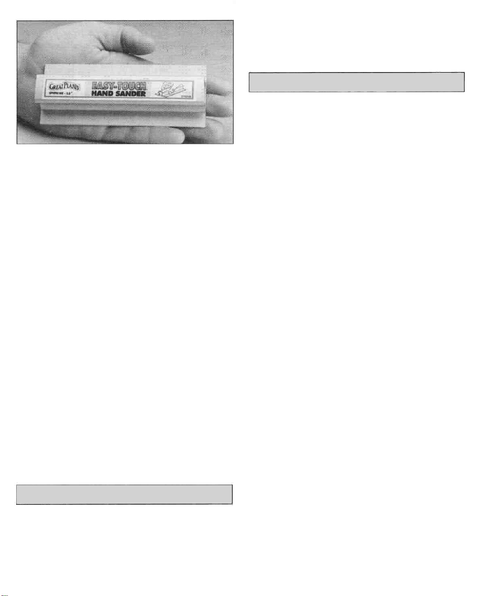
A flat, durable, easy-to-handle sanding tool is a
necessity for building model airplanes. Great
.Planes makes a complete range if Easy-Touch"
Bar Sanders and replaceable Easy-Touch
adhesive-backed sandpaper. On our workbench,
we have four 11" Easy-Touch Bar Sanders,
equipped with #50, #80, #150 and #220-grit
sandpaper. This setup is all that is required for
almost any sanding task. Custom sanding blocks
can be made from balsa for sanding hard-to-
reach spots. We also keep some #320-grit wetor-dry sandpaper for finish sanding before
covering.
the pieces as you cut them for later reference.
By doing this now, you won't have to splice
pieces together later.
ADHESIVES
This kit is built with three types of glue.
Cyanoacrylate: CA glues cure almost instantaneously
and are moderately strong. There are different
viscosities of CA's intended for different
conditions you will encounter when you build.
Thin CA is great for "tack-gluing," for glue joints
that fit well and for parts that are already joined
but need to be permanently bonded. Medium
CA is used for general construction where you
apply glue to one part, then join it to another
part. Thick CA is great for glue joints that don't
fit perfectly or parts that require a little time for
positioning before the glue cures. You will
encounter many other conditions that require
one or the other types of CA.
For future reference, here's a list of Easy-Touch
Bar Sanders and adhesive-backed sandpaper:
5-1/2" Bar Sander(GPMR6169)
11" Bar Sander (GPMR6170)
22" Bar Sander (GPMR6172)
12' Roll of adhesive-backed sandpaper,
80-grit(GPMR6180)
150-grit(GPMR6183)
220-grit (GPMR6185)
Assortment pack of 5-1/2" strips (GPMR6189)
BUILDING NOTES
IMPORTANT: During construction you will be
using a number of balsa sticks to frame various
assemblies. Ample material is included but you
should study the plans, then make an effort to
cut the longest pieces you will need first. Label
Always use CA in a well ventilated area. Open
some windows or place a fan in the room to
circulate the air. Do not lean directly over your
work when you use CA and look away while it
cures or "sets off." CA can cure immediately
upon contact with skin so if you accidentally
bond your fingers, do not use vigorous motion
to separate them. Use CA Debonder (GPMR6039)
or acetone (nail polish remover) or soak your
fingers in warm water for a few minutes.
Never point the tip of a CA bottle toward your
face and be especially careful when you unclog
a CAtip. Hobbico CAApplicatorTips (HCAR3780)
are highly recommended and will help keep the
bottle from clogging. Keep paper towels or
tissues close by to immediately absorb excess
CA dropped on your model or work area. Read
all the warning labels on your CA bottle. CA
Accelerator is a chemical that you can spray
over uncured CA to make it cure immediately. A
mist spray of accelerator will do the job. Do not
inhale the vapors! Some modelers "preprime"
5
Page 6
the parts to be glued with accelerator, join
them, then add the CA. This way the CA is
guaranteed to cure immediately. This
prepriming is especially handy when you use
thin CA because it will cure before all of the
glue soaks into the wood away from the joint.
We do not recommend you build your entire
model with this method and use accelerator
only when necessary. Often, overspray from
accelerator used hours or even days earlier on
nearby glue joints will cause the CA you use on
the next step to cure prematurely and
unexpectedly - so be careful!
Throughout the assembly of this model, THIN
CA should be used unless the step calls for
another type of adhesive.
minute epoxy is the strongest as it allows the
epoxy to soak into the wood thoroughly. While
itsets within 30 minutes, it is not fully cured for
two or more hours.
COMMON
Fuse = Fuselage
Ply = Plywood
" = Inches
ABBREVIATIONS
Stab = Horizontal Stabilizer
LE = Leading edge (front)
TE =Trailing edge (rear)
Aliphatic Resin: Resin glues require that parts
be pinned or clamped together while the glue
dries; typically 15 - 30 minutes. Resin glues are
very strong and work well with balsa and
plywoods.
Epoxy: Epoxy glues are the strongest but
require the most time to cure. Six-minute epoxy
cures the fastest; it sets within six minutes but
is not fully cured for one hour or more. Thirty-
Inch Scale
0"
1"
2"
3"
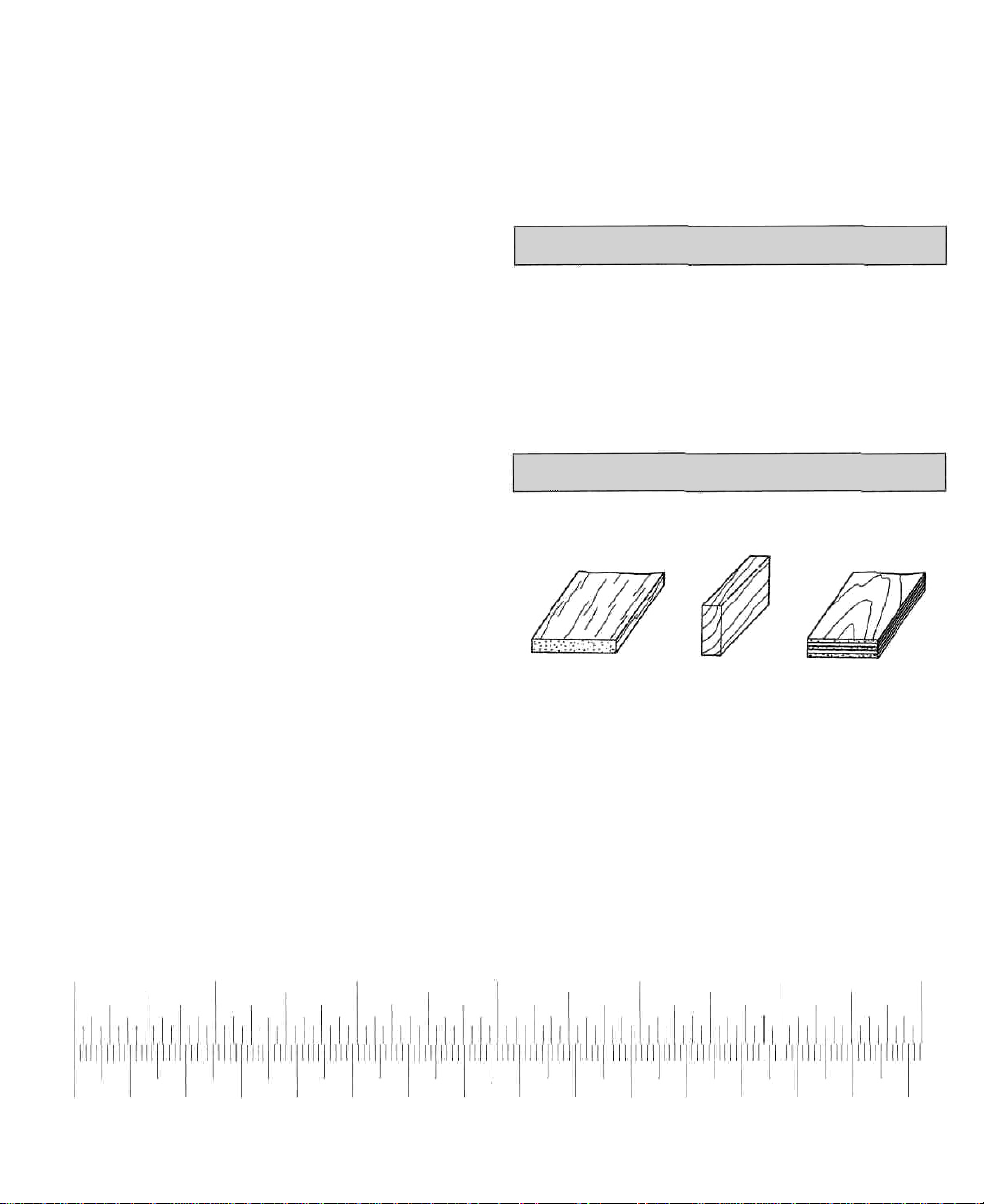
TYPES OF WOOD
Balsa Basswood Plywood
4"
5"
6"
0 10 20 30 40 50 60 70 80 90 100 110 120 130 140 150
Metric Scale
6
Page 7
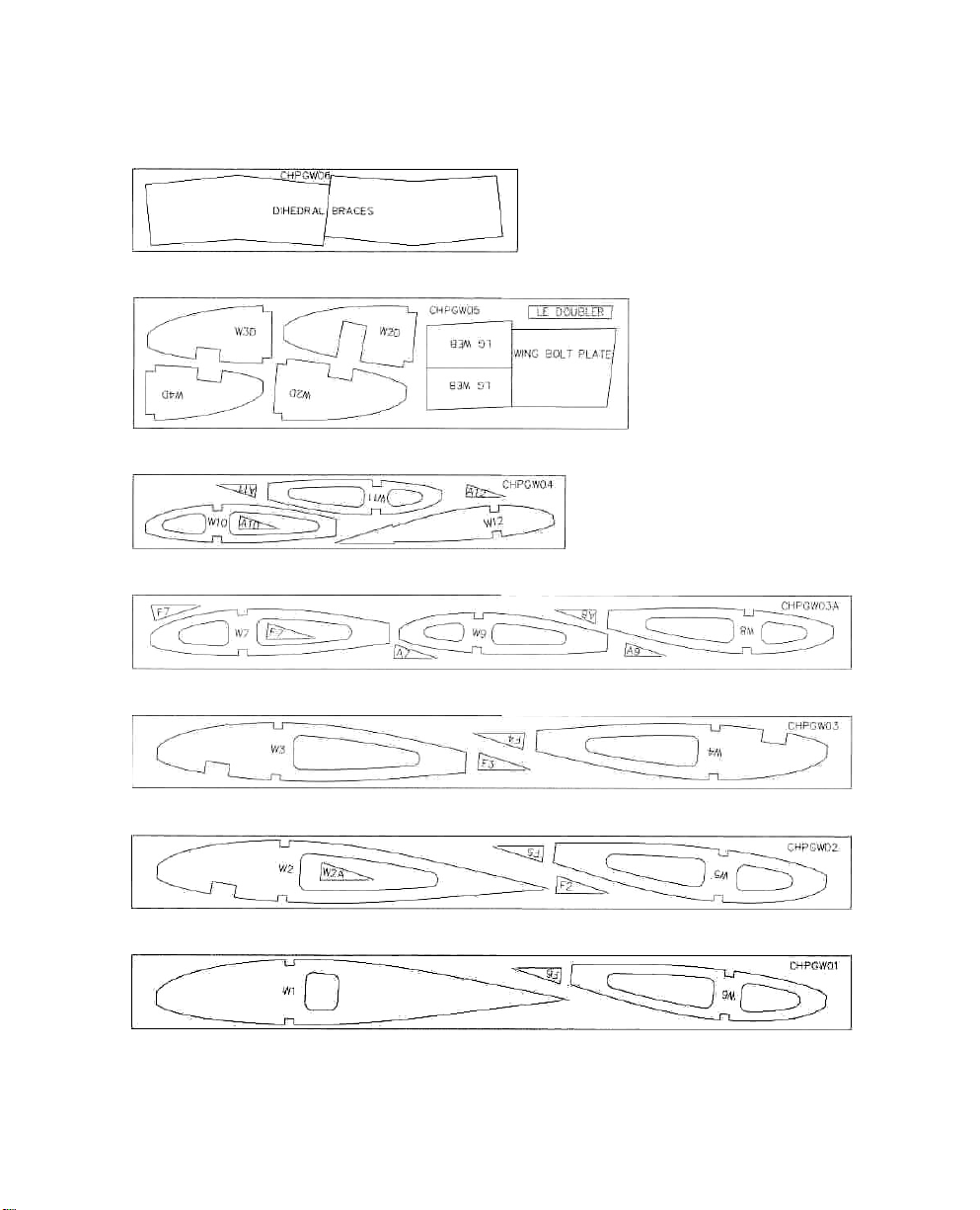
Die-Cut Pattern
CHPGIPW06
1/16" X 3-3/8" X 16" PLY
CHPGW05
CHPGW04 2 REQ.
CHPGW03A 2 REQ.
1 REQ.
1/8" X 5-3/8" X 20-5/8" PLY
3/32" X 3" X 18" BALSA
Note: If you will be building functional flaps for your
Chipmunk, glue in the lightening holes in ribs W4
and W5.
Note: This page shows the location of the die-cut
parts for the wing. Not all parts are marked on the die
sheets. Be sure to mark all parts with a ball point pen
prior to removing them from the die sheets.
2
REQ,
3/32" X 3" X 30" BALSA
CHPGW03 2 REQ.
3/32" X 3" X 30" BALSA
CHPGW02 2 REQ.
3/32" X 3" X 30" BALSA
CHPGW01 2 REQ.
3/32" X 3" X 30" BALSA
7
Page 8
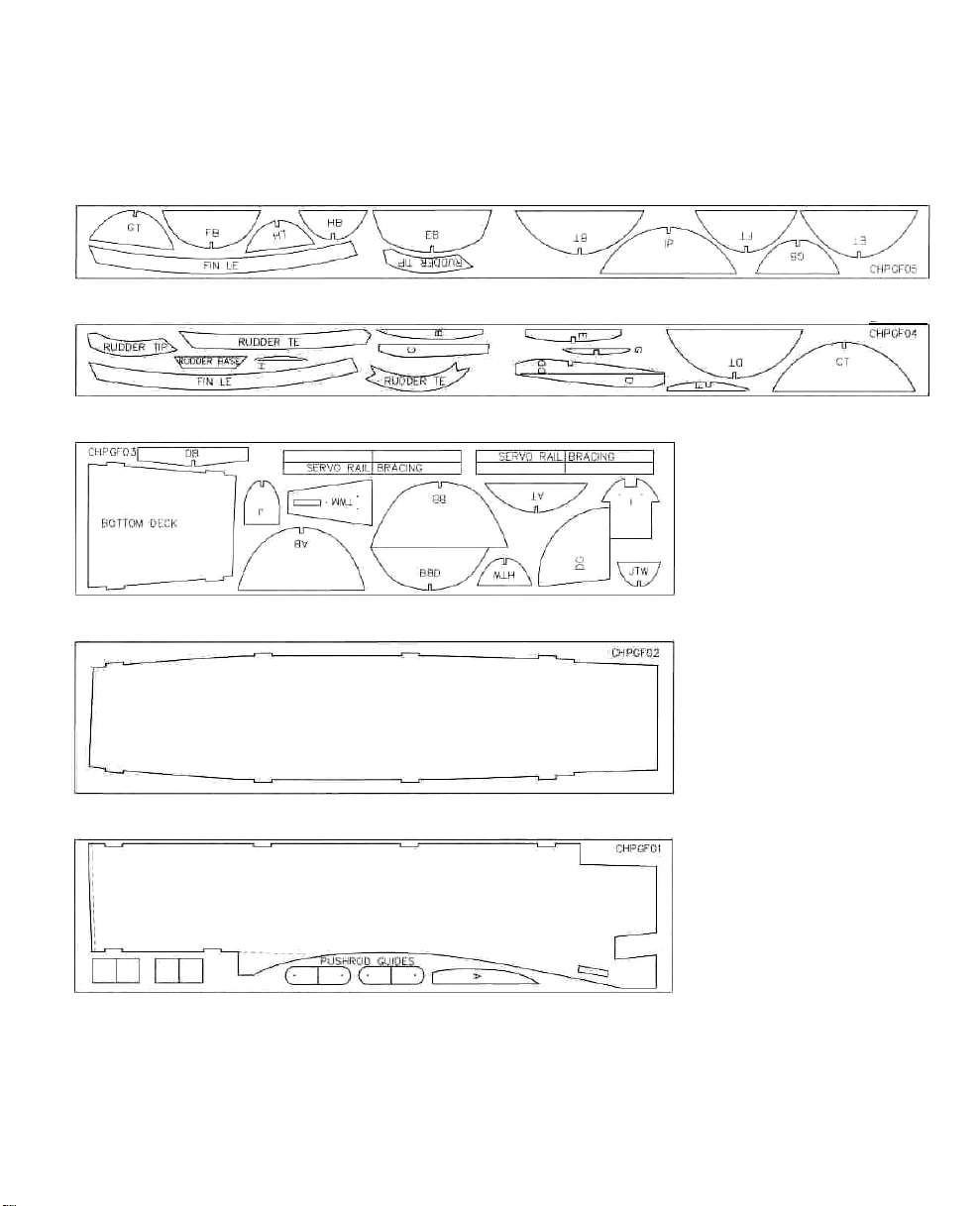
Die-Cut Pattern
CHPGF05 1 REQ.
1/8" X 3" X 36" BALSA
CHPGF04
1/8" X 3" X 36" BALSA
CHPGF03 1 REQ,
1/8" X 6-3/8" X 25-1/4" PLY
CHPGF02 1 REQ.
2
REQ.
TOP DECK
1/8" X 6-3/8" X 25-1/4" PLY
CHPGF01 2 REQ.
FUSELAGE SIDE
CONTROL
HORN
MOUNTS
1/8"
X
6-3/8" X 25-1/4"
PLY
Note: This page shows the location of the
die-cut parts for the fuselage. Not all parts are
marked on the die sheets. Be sure to mark all
parts with a ball point pen prior to removing
them from the die sheets.
8
Page 9
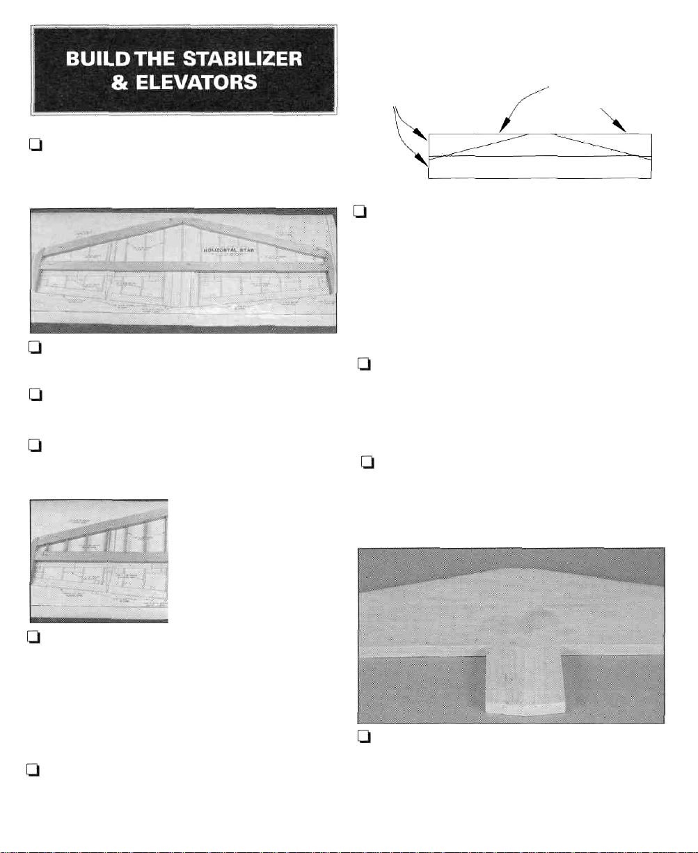
STAB SHEETING
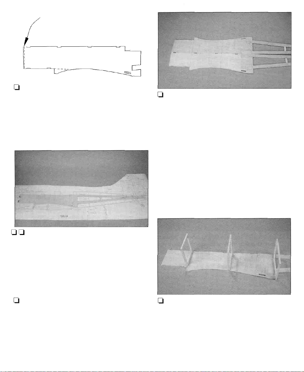
1. Cut the stabilizer drawing from the fuselage
plan and place it on your building board. Cover
the plan with Great Planes Plan Protector.
Q 2. Cut the trailing edge from 1/2" x 15/16" x
36" balsa and pin it in place over the plan.
Ql 3. Cut both leading edges from 1/2" x 15/16"
x 36" balsa and pin them in place over the plan.
Q 4. Cut and fit the ribs from 1/8" x 1/2" x 30"
balsa. Cut the longer ribs first. When satisfied
with the fit, glue them into position.
1/16"X3"X30"
BALSA SHEETING
USE LEFTOVER
FOR FIN SHEETING
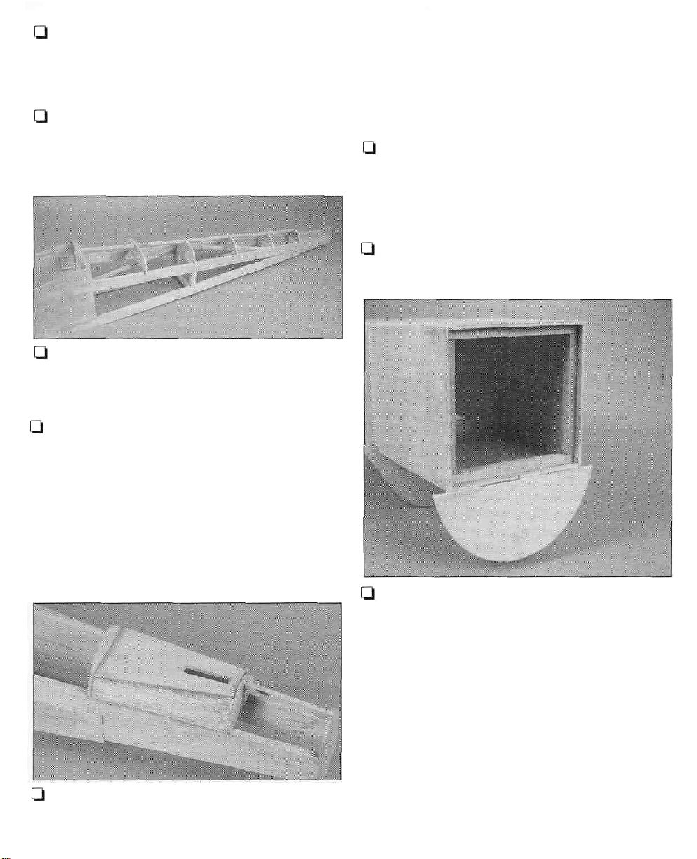
Q7. Sheet the stab with 1/16" x 3" x 30" balsa on
both the top and bottom. Do this with the stab
flat on your building board and use care not to
twist it as you glue the sheeting into place. Use
pieces of leftover 1/16" balsa sheeting to sheet
the stab tips.
Ql 8, Sand the trailing edge of the stab flat as
shown on the cross-section of the plan. Rough
sand the stab to the shape shown.
I—I 9. Mark the centerline on the rear edge of the
TE along its entire length.
l-l 5. Cut and shape the tips from 1/2" x 3/4" x
12" balsa using the plans as a guide. Glue and
pin them in place.
Note: It is important that the ribs fit the LE and
TE well. It is not important that each rib fit the
exact location shown on the plan.
Q 6. Remove the stab from the plan. Sand the
top and bottom surfaces flat and even. Use care
not to gouge any of the ribs.
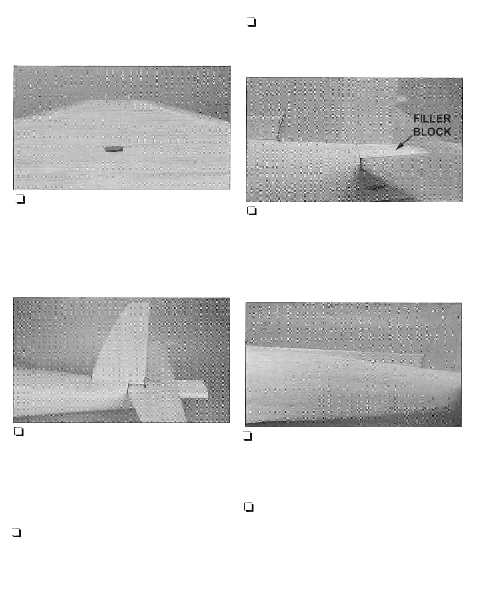
LI 10. Cut the four stab filler blocks from 5/8" x
15/16" x 18" balsa and glue them to the center of
the stabTE as shown on the plan and photo.
Note that two of these blocks are cut to a width
of 3/4".
9
Page 10
Q 16. Notch the LE of both elevators where
shown on the plan and fit and glue the die-cut
1/8" ply horn bases into place.
Q 17. Remove the elevators from the plan and
rough sand them to the shape shown in the
cross-section. Use care not to gouge the ribs.
[.-111. Build both elevators at the same time. Cut
the leading edges from 5/8" x 1/2" x 30" balsa
and pin them to the plan.The leftover 5/8" x 1/2"
balsa will be used later for hinge blocks.
Ql 12. Cut some shims from 3/16" x 3/8" x 24"
balsa and place them in position over the plan
at theTE.The remainder of this stick will be used
for the fin ribs so be sure to save at least 14".
l-t 13. Cut the trailing edges from 1/4" x 3/4" x
30" balsa. Pin them into position on top of the
shims.
Q 14. Cut and fit the eight elevator hinge blocks
from 5/8" x 1/2" x 30" balsa. Glue them into
position where shown on the plan.
Q 18. Mark
leading edges along their entire length. Using
the cross-section on the plan as a reference,
sand
shown. Make sure the angle of the "V" is
enough to allow for the full up and down
movement of the elevators.
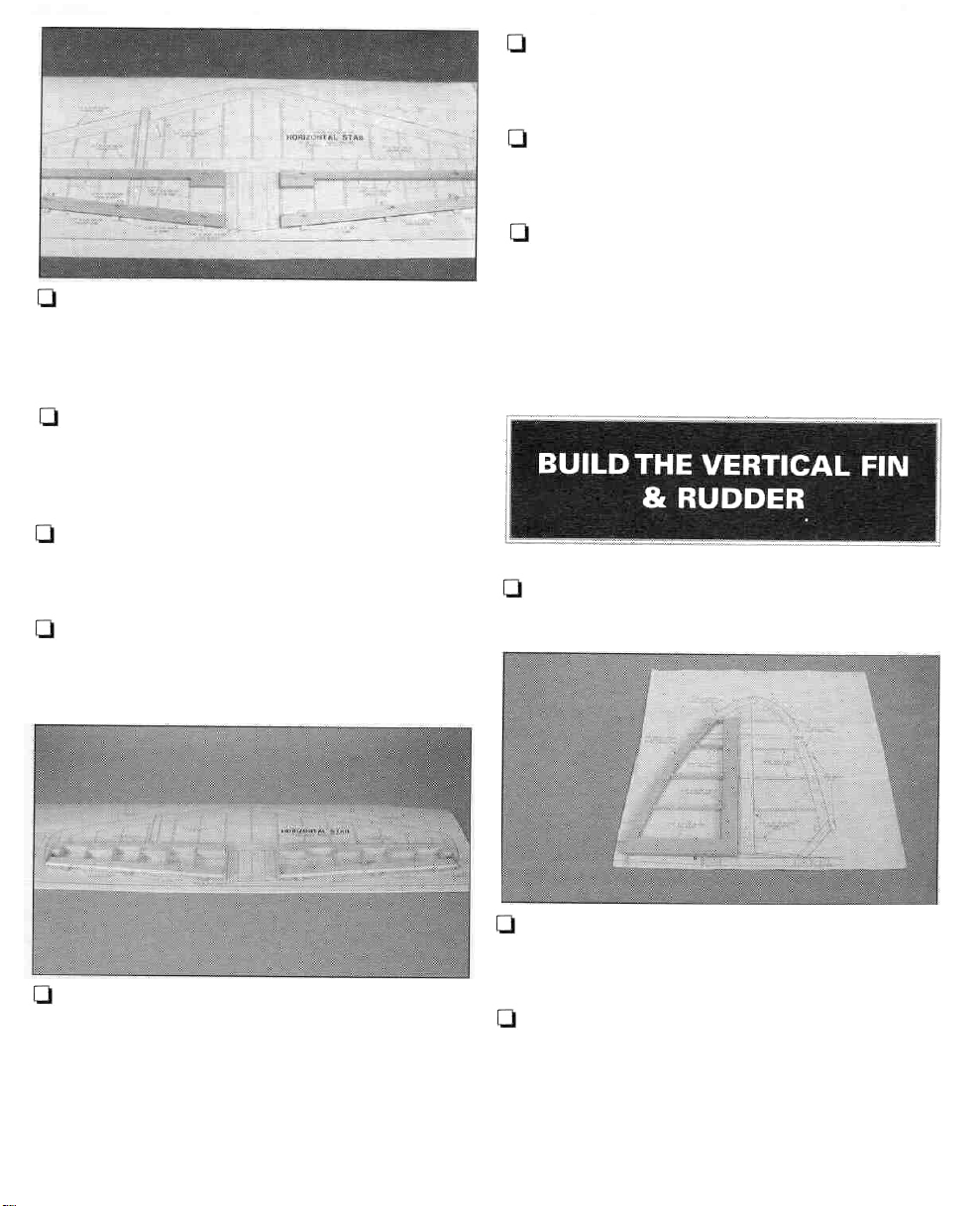
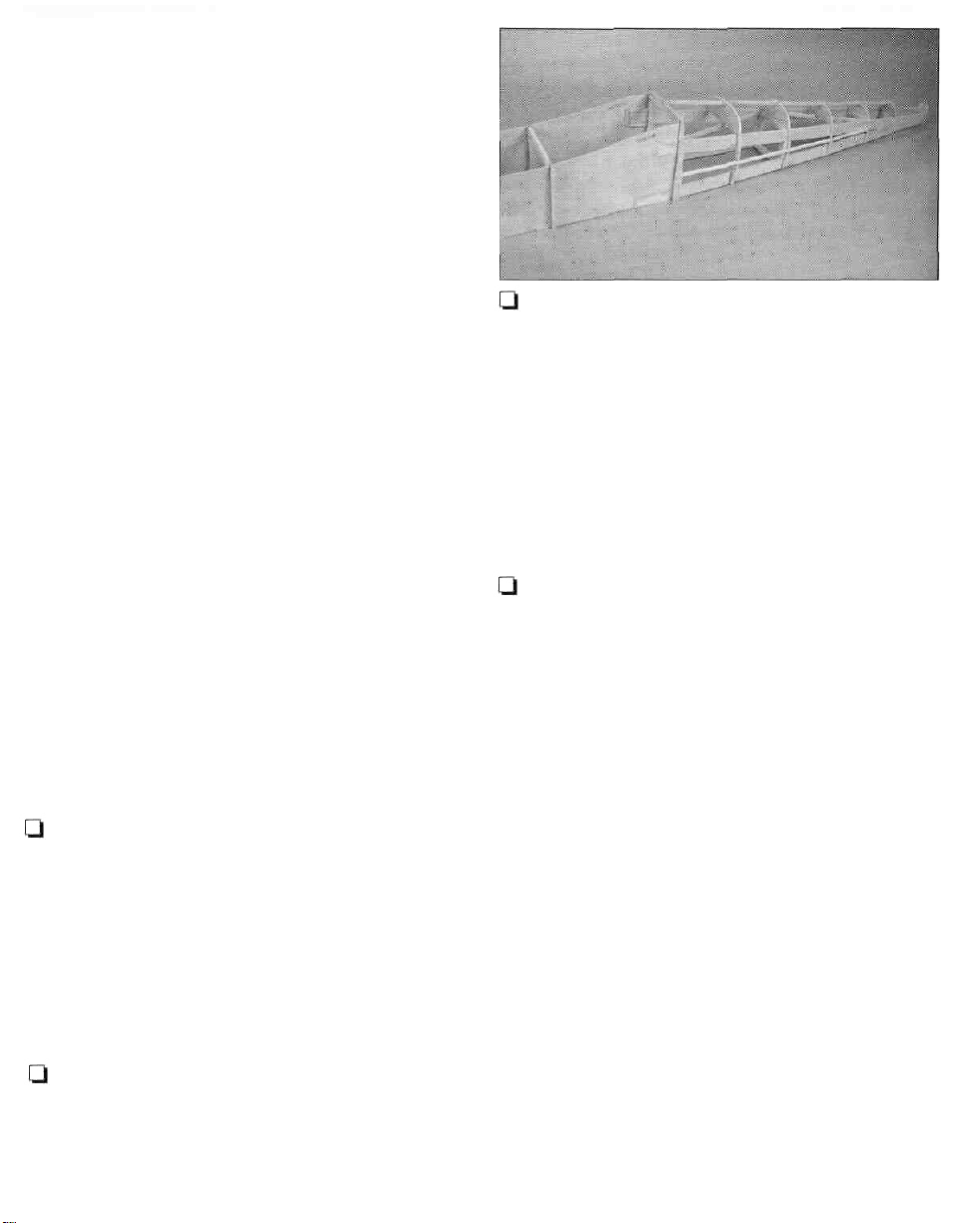
Q 1. Cover the fin/rudder drawing with Plan
Protector.
the leading edges to the "V" shape
the
centerline
of the
elevator
Ql 15. Cut and fit the ribs from 1/8" x 5/8" x 36"
balsa. Cut the longer ribs first. When satisfied
with the fit, glue them into position. Note that
the root and tip ribs extend full length. Note: It
is important that the ribs fit the LE andTE well.
It is
not
important that each rib fit the exact
location shown on the plan.
Q 2. Glue the three die-cut 1/8" balsa fin leading
edge pieces together to form a LE lamination.
Pin this in place over the plan.
[-I 3. Cut the fin post (trailing edge) from 3/8" x
15/16" x 18" balsa and pin it in position.
Q 4. Cut the fin base from the remaining 3/8" x
15/16" balsa and pin it into position. Glue all
three pieces together.
10
Page 11
5. Cut and fit the ribs from the remainder of
the 3/16" x 3/8" x 24" balsa. Cut the longer ribs
first. When satisfied with the fit, glue them into
position.
Note: It is important that the ribs fit the LE and
TE well. It is
not
important that each rib fit the
exact location shown on the plan.
Q 6. Remove the fin from the plan. Sand the top
and bottom surfaces flat and even. Use care not
to gouge any of the ribs.
FIN SHEETING
LEFTOVER
STAB SHEETING
Q 10. Cut the rudder base from the rest of the
1/2" x 15/16" balsa. Glue and pin it into place.
I—I 11. The rudder tip leading edge is built up
from three laminations of die-cut 1/8" balsa
pieces, for a total thickness of 3/8". Glue the
three pieces together and pin them in place on
the plan, using some leftover 1/16" balsa shims
where shown.
Q 12.The rudder trailing edge is built from two
laminations of die-cut 1/8" balsa pieces, for a
total thickness of 1/4". Build two of these
assemblies using the plan as a reference.
Q 13. Cut some shims from leftover 1/8" balsa
and place them in position over the plan at the
TE where shown. Pin and glue the TE into
position.
SCRAP
SHEETING
1/16" X 3" X 10-1/2"
BALSA SHEETING
LJ 7. Sheet the fin with 1/16" x 3" x 30" balsa on
both sides. Do this with the fin flat on your
building board and use care not to twist it as
you glue the sheeting into place.
Q 8. Rough sand the fin to the shape shown in
the cross-section.
Q 9. Cut the rudder leading edge from 1/2" x
15/16" x 18" balsa and pin it to the plan.
Q 14. Cut and fit the ribs from 3/16" x 1/2" x 18"
balsa. Cut the longer ribs first. When satisfied
with the fit, glue them into position.
Note: It is important that the ribs fit the LE and
TE well. It is
not
important that each rib fit the
exact location shown on the plan.
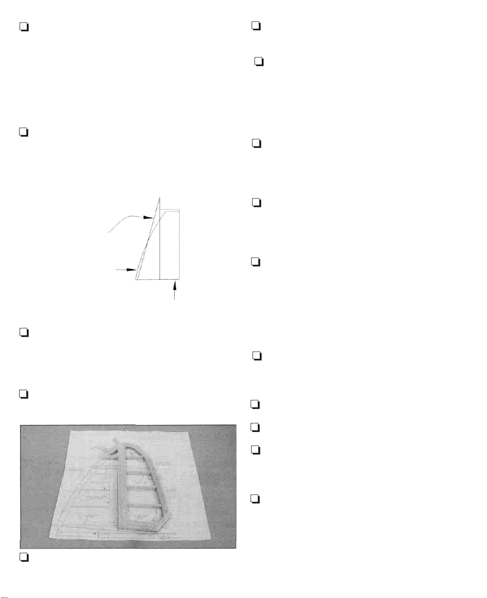
Q 15. Remove the rudder from the plan and
rough sand it to the shape shown in the cross-
section.
Q 16. Tack glue the rudder to the fin.
Q 17. Sand the assembly to its final shape.
Q 18. Separate the rudder from the fin. Sand
the trailing edge of the fin flat as shown on the
cross-section on the plan.
Q 19. Mark the centerline of the fin trailing edge
and rudder leading edge along their entire
length. Using the cross-section on the plan as a
reference, sand the rudder leading edge to
the "V" shape shown. Make sure the angle of
the "V" is enough to allow for the full left and
right movement of the rudder.
11
Page 12
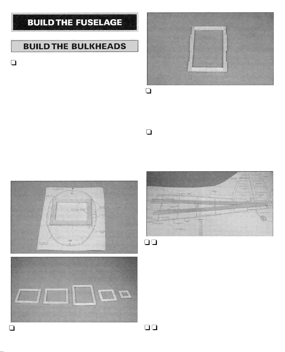
Q 1.The fuselage plan is in two pieces. Cut the
plan as indicated and tape the two parts
together. Cut the fuselage top view from the
plan. Cut the drawings for bulkheads B, C, D, F
and H from the plan. Place the bulkhead
drawings on your workbench and cover them
with Plan Protector.
[-I 3. Inner bulkhead D has notches cut in the
sides for the longerons and longeron doublers.
These notches may be cut now or later when
the inner bulkhead is fitted to the fuselage side.
Q 4. Place the fuselage side plan on your
workbench and cover it with Plan Protector
from bulkhead D aft. Begin construction by
building the right rear side structure.
Q 2. Build inner bulkheads B, C, D, F and H over
the drawings using 1/4" x 1/2" x 24" balsa sticks.
l-t Q 5. Using two 1/4" x 15/16" x 36" balsa sticks,
cut and fit the rear side longerons. Pin and glue
the parts into position.
Note: The top longeron ends at the leading
edge of the stab. A separate 1/4" x 15/16" x 5-9/16"
stab mount is glued to the rear of the top
longeron, 1/8" below the top edge. The bottom
longeron has an angled cut and notch that fit
the top longeron and stab mount.
Q l-l 6. Cut the upright at bulkhead F from 1/4"
x 1/2" x 24" balsa and glue it into position.
12
Page 13
CUT ALONG
EMBOSSED LINE
RIGHT FUSE SIDE
[-] 7. Locate one of the die-cut 1/8" ply forward
fuselage sides. Cut off the front end of this side
along the embossed line.This will establish two
degrees of right thrust. Note: Only the right
forward fuselage side has this cut made.
I-J10. Place the right fuselage side over the plan
and mark the locations of bulkheads B, C, D, E,
F, G, H, HTW and I on the side. Place the left side
over the right and transfer the marks to the left
side. Next, mark each inner bulkhead at the
center of the top edge. These marks and lines
will be used to align the fuselage in the
following steps.
l-l Q 8. Fit this ply fuselage front to the fuse rear.
Cut doublers for the two joints from 1/8" x 1/4"
x 30" balsa. When satisfied with the fit, glue the
ply front and doublers to the fuse rear with
6-minute epoxy.
Q 9.The left fuselage side is built over the right
side. Remove the right side from your building
board and turn it over. Use the leftover 1/8" x
1/4" stick to shim the forward ply side. Cover the
side with Plan Protector. Follow steps 5, 6 and 8
to build the left side, aligning the parts over the
right side. Do not cut the front end of the
left forward ply side.
Q 11. Glue inner bulkheads B, C and D to the
right fuselage side using 6-minute epoxy. Be
sure the bulkheads are at a 90° angle to the
side. Epoxy will produce the strongest joint but
you can use thin CA with accelerator if you are
in a hurry. Inspect each joint for gaps and re-glue
if necessary. Note:
The
top edge of each bulkhead
is 1/8" below the top edge of the ply side.
13
Page 14

Q 12. Glue the die-cut 1/8" ply fuselage top and
bottom decks to the right fuselage side. The
parts interlock. Do not glue the bulkheads to the
decks. IMPORTANT: Be absolutely certain that
the shorter side of the top and bottom decks are
glued to the right ply side. This establishes the
proper amount of right thrust. The front of each
deck should extend exactly to the front of the
ply fuselage side.
t_] 15. Lightly sand the sides of bulkheads F and
H to match the slope of the sides. Install them in
their proper locations in the fuselage sides and
hold them in position with pins. Do NOT glue
until later.
Q 16. Place the fuselage upside-down over the
top fuselage plan. Align the top deck with the
plan and pin it into place. Use some blocks to
hold the tail of the fuselage in place over the
plan. Align the center mark on each bulkhead
with the centerline on the plan. Sight down
from above the fuselage to double check the
alignment. When you are satisfied that
everything is aligned properly, glue bulkheads
F, H, and J to the fuselage sides.
Q 13. Glue the left fuselage side to inner bulkheads
B, C and D using 6-minute epoxy. Align the
bulkheads with the marks you made earlier.
Before the epoxy cures, sight across the top of
both sides to double check the alignment.
Q 14. Pull the tail together and tack glue die-cut
1/8" ply bulkhead J to the rear of the longerons.
Q 17. Use the 1/4" x 1/4" x30" balsa stick to glue
a cross-brace between bulkhead D and F, and
between F and H.This bracing will make the tail
more rigid.
l-l 18. Glue the die-cut 1/8" ply bottom bulkhead
formers AB and BB for bulkheads A and B into
position. Glue doubler BBD to the FRONT of BB.
Note: Make sure that AB follows the angle
established for the firewall. Use side formers A
and B to help in centering AB and BB.
14
Page 15
Q 19. Cut a stringer from 1/8" x 1/4" x 31"
basswood to length and glue into place to the
bottom of formers AB and BB.The remainder of
this stringer will be used on the top formers.
Ql 20. Bend the forward part of the wing saddle
on the 1/8" ply fuselage side along the
embossed cut line so that it conforms to BB.
Glue it into position.
Q 21. Glue the die-cut 1/8" balsa bottom
bulkhead formers EB, FB, GB, HB and HTW into
position.
l-l 22. Tack glue the die-cut 1/8" ply bulkhead
former DB to the FRONT of bulkhead D. Glue
another 1/8" x 1/4" x 31" basswood stringer to
the bottom of formers DB, EB, FB, GB, HB
and HTW.
fuselage side view as a guide. These mount
blocks are glued to the bottom longeron at an
angle to conform to the curve on bottom
formers HTW and JTW. Sand the blocks as
needed for this angle and glue them to the
bottom longeron.
Q 24. Glue the die-cut 1/8" ply tailwheel mount
into position on these blocks. Glue the die-cut
1/8" ply former JTW to the rear of this
assembly. Glue a piece of 1/8" x 1/4" basswood
stringer between JTW and J.
Q 25. Remove the fuselage assembly from the
building board.
Note: The exact position of DB will be
determined when the wing is fitted to the
fuselage. For now, just tack glueit so that the
stringer is straight.
Q 23. Cut and fit the tailwheel mount blocks
from leftover 1/4" x 15/16" balsa using the
I-] 26. Time to mount your engine. Before you
glue the firewall into position, you should add
some reinforcing sticks to the inside of the
fuselage as shown in the above photo. Use the
1/4" x 3/8" x 36" basswood stick for this purpose
(DO NOT use the longer basswood wing
spars). Glue them into position with 30-minute
epoxy. While you are waiting for the epoxy to
cure you can mount your engine to the engine
mount you have chosen. Position the mount on
the plan at the firewall then locate the engine on
the mount to fit the front of the cowl properly.
Check the position on the model to be sure
blind nuts and bolts will clear the structure. If
15
Page 16
you
will
be
using
the Great
Planes
Isolation
Mount™ you will need to reposition the
Mounting Grommets as shown on the plan.
Note: Depending on the type of engine you are
installing, you may need to add spacers
between the engine mount and firewall. Layers
of
aircraft grade 1/4" plywood (not included)
work well for this. The firewall location is
designed so that a typical gasoline engine can
be
mounted on a Great Planes Isolation Mount
(GPMA2000, not included).
Gasoline Engine Note: Gasoline engines
mounted on an isolation mount, such as the
Great Planes Large Engine Isolation Mount™,
may need to be mounted on the centerline of
the model. This is needed to obtain clearance
between the mounting bolts of the isolation
mount and the engine on the relatively narrow
firewall. Shim the engine as needed to obtain 0°
of right thrust (about 1/8").
Q 29. Glue the die-cut 1/8" ply and balsa side
bulkhead formers A, B, C, D, E, F, G and H into
position on both sides of the fuselage. The flat
end of A and B goes towards the bottom of the
fuselage. The flat end of the rest of the formers
goes towards the top of the fuselage (E and F
can be glued on either way). The angled end of
C goes towards the bottom. Glue side former
DD to the rear of D. Note that DD is slightly
wider than D and should protrude from D by
about 1/32".
Ql 30. Cut two 3/16" x 3/16" x 24" balsa stringers
to length and glue them into place on side
formers DD, E, F, G and H.
Most engines will fit inside the cowl if the engine
is mounted inverted. Be sure to allow for adequate
cooling.
Q 27. Drill the 1/4" x 4-1/8" x 4-1/4" ply firewall
as needed for your engine mount and install
any required blind nuts. Glue the firewall to the
fuselage with 30-minute epoxy. For added security
you can pin the firewall to the fuselage if
desired. Drill small holes through the sides of
the fuselage into the firewall and epoxy in small
dowels or toothpicks.
Ul
28.
Once the epoxy has cured, install any
spacers needed for your engine mount. Be sure
to install any blind nuts required to bolt your
engine mount to the spacers.
Now is a good time to install the servos and
route the servo pushrods before any more
formers and sheeting are glued into place.
There are eight die-cut 1/8" ply pushrod guides
provided for this purpose. You may also need
some leftover 1/4" x 3/4" balsa sticks as well.The
plan shows the servos mounted just forward of
theTE of the wing.This is a good location if you
will be using a lighter engine such as a 1.20
4-stroke engine. Our prototype model, with an
O.S. FS-120 Surpass 4-stroke engine, balanced
without any lead required with the servos
positioned as shown on the plan. If you will be
using a heavier gasoline engine you may want
to mount the servos in the tail of the model.This
can be done easily by notching the longerons
for the servos, allowing them to protrude from
the fuselage side. If you do this, use some
leftover 1/4" x 3/8" basswood to reinforce the
longerons.
16
Page 17
Note: If you will be entering your Chipmunk in
IMAA events you need to review their
requirements for servo and control linkage
sizes. They require high-torque servos on
control surfaces and 4-40 size control linkages,
with metal clevises.
Q 31. Install the servos and route the pushrods
for the servo installation you will be using.
Note:
You
will need to temporarily mount the
tailwheel assembly. The lower side longeron
will need to be carved out in the area where the
pushrod clevis will connect to the rudder torque
rod horn.
Q 33, Glue the die-cut 1/8" ply and balsa top
bulkhead formers AT, BT, IP, (2) CT and (2) DT
into position.
Note: Make sure that AT follows the angle
established for the firewall.
Q 34. Cut a 1/8" x 1/4" x 31" basswood stringer
to length and glue into place to top formers AT,
BT and IP. Do the same for the two CT top
formers. Use the remainder of the 1/8" x 1/4" x
31" stringer used on the bottom formers.
Q 32. Glue the 1/4" x 1-1/4" x 5-1/4" ply wing
hold down block into the slots in the fuselage
sides with 30-minute epoxy. Cut and glue some
1/4" x 3/8" reinforcing sticks into place using a
leftover basswood stick.
Q 35. Glue the die-cut 1/8" piy and balsa top
bulkhead formers ET, FT, GT, HT and I into
position.
Q 36. Cut a 1/8" x 1/4" x 31" basswood stringer
to length and glue into place to top formers DT
(both), ET, FT, GT and HT.
17
Page 18
1-1 37. Glue two sheets of 1/8" x 3" x 24" balsa
together to form a sheet 6" wide. Sand the outer
side of this sheet flat and smooth. Cut, fit and
glue this sheet into position to the left fuselage
side between side formers A and D with the
smooth side out. Align the top edge of the sheet
even with the top of the top deck. Note: This
sheet should extend only to former D and
should not cover DD. Wet the sheeting as
needed to allow it to bend better.
D 38. Make and glue a second balsa sheet to
the right fuselage side.
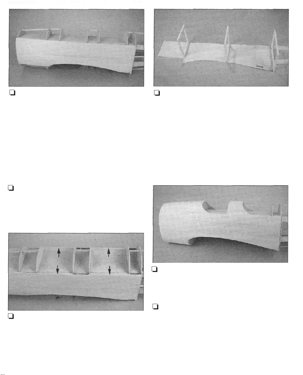
Q 40. Use some more leftover 1/8" balsa
sheeting to cut, fit and glue filler strips between
the side sheeting and the ply fuselage sides at
the wing saddle area. Angle the strips slightly to
conform to the 6° dihedral angle of the wing.
Note:
There
is a small section of sheeting that
needs to be added at bulkhead D. This will be
added later when the fuselage bottom is
sheeted.
Q 41. Use 1/8" x 3" x 30" balsa to sheet the top
of the fuselage between AT and IP Also sheet
the area between the front and rear CT's.
Q 39. Using some leftover 1/8" balsa sheeting
cut, fit and glue filler strips between the
sheeting you just added and the fuselage top
deck. You only need to do this in the area of the
front and rear cockpits, between top formers IP
and CT and between CT and DT.
LI 42. Use leftover 1/8" x 3" balsa sheeting to
sheet the bottom of the fuselage between AB
and
BB.
Before the rear of the fuselage is sheeted the wing
must be fitted to the fuselage. So, it's time to:
18
Page 19
Q Q 1. Lay the right wing plan on your building
board and cover it with Plan Protector.
Note: It will be easier if you prepare all four
leading edge wing skins at the same time.
BOTTOM WING SKIN
USE LEFTOVER
FOR OTHER SKIN
3/32"
X 3" X
BALSA SHEETING
42"
CUT
CUT FROM
CORNER
TO CORNER
SAVE LEFTOVER FOR
FUSE SHEETING
3"
WIDE
3/32"
BALSA SHEETING
TOP WING SKIN
3/32" X 3" X 42"
BALSA SHEETING
3/32" X 3" X 48"
BALSA SHEETING
X 3" X 48"
CUT LINE
LINE
6-3/8"
WIDE
SCRAP
BALSA
SCRAP
BALSA
6" WIDE
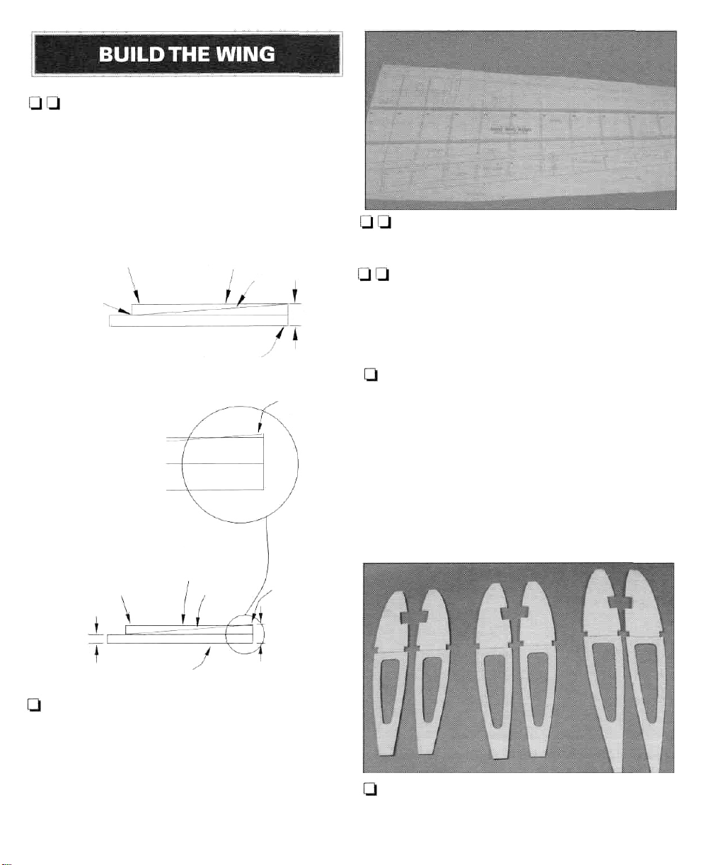
Q 2. Prepare the four leading edge wing skins
according to the sketches above. The skins for
the top of the wing are 3/8" wider than those for
the bottom. Glue the skins together using your
favorite method (we use masking tape to form
a hinge and then join them with aliphatic resin
glue). Sand the best side smooth with 150-grit
sandpaper.
U U 3. Pin the 1/4" x 3/8" x 44" basswood lower
spar over the plan.
l-l t-l 4. Pin a 1/4" x3/8" x 44" basswood stick on
the dashed lines called "shim stick." This will
hold the rear of the ribs at the proper angle until
there are enough pieces to hold the wing rigid.
(Save the shim stick for later use.)
Q 5. Punch the ribs from their die-cut sheets,
sanding the backs of the sheets lightly if they do
not come out easily. Number each rib as you do
so; don't forget to number the aileron and flap
ribs as well. Check the fit of the spar to the spar
notches in each rib.
Note: If you will be building functional flaps for
your Chipmunk, glue in the rear lightening
holes in ribs W4 and W5.
Q 6. Glue the die-cut 1/8" ply landing gear
doublersto ribsW2,W3 andW4 using 30-minute
epoxy. Glue them to the sides shown on the
19
Page 20
plan. There are two doublers for W2. The one
with the long cutout is glued to the side facing
the wing root. This cutout will lock in the
landing gear stub (torque) block. Check the fit of
the landing gear block and stub block in their
cutouts. Make sure you make a set for the right
and left wing panels.
I-] Q 7. Glue ribsW2 -W12 into place on the lower
spar with a drop of CA, making sure they are
vertical. Pin the rear of each rib to the shim stick.
Q Q 9. Glue the 1/4" x 3/8" x 44" basswood top
spar to the ribs.
Q Q 10. Cut a 1/4" x 3/4" x 24" balsa stick to the
correct length and glue it to the rear of W8-W12.
The tip end is glued to the side of W12. Glue the
top flush with the top edges of the ribs.The stick
extends midway between W7 andW8.
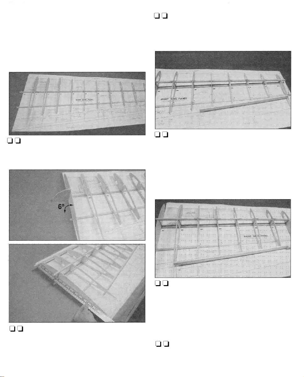
Q Q 8. Use the dihedral gauge to obtain the
proper angle (six degrees) ofW1. GlueWl into
place on the lower spar. Pin the rear ofW1 to
the shim stick. Use a long straightedge to insure
thatWI is straight.
Q Q 11. Cut a 1/4" x 7/8" x 30" balsa stick to the
correct length and glue it to the rear ofW2 -W8.
The root end is glued to the side ofW2. The tip
end glues to the side ofW8 and the front of the
outerTE.
Q Q 12. Use the remainder of the 1/4" x 7/8"
balsa stick to cut and fit aTE piece between W1
andW2.
20
Page 21
13. Glue the 1/4" x 1/2" x 48" balsa leading
edge stick to the front of the ribs. Align the top
of the LE even with the tops of the ribs. Use a
long metal straightedge to get the LE as straight
as possible. IMPORTANT: Use a straightedge
along the sides of W1 and W12 to insure that
they are straight and flat.
Q Q 14. Use a 3/32" x 4" x 36" balsa sheet to
prepare the spar webs. Note: The sheeting
provided is ample to prepare all of the webs,
but there is no extra material so work carefully.
There is webbing from W2 to W12 glued to the
front of the spars and from W2 to W9 glued to
the rear of the spars. Start with the ribs that are
spaced the widest first. Trim and sand the sheet
to fit between the two ribs. Sand the bottom
edge of the sheet to fit the angle of the lower
spar, then mark and cut the sheet to the proper
height. Continue cutting, trimming, sanding, and
gluing the sheet for all of the webbing. Be sure
to remove any pins that will be hidden by the
webbing before gluing it into position.
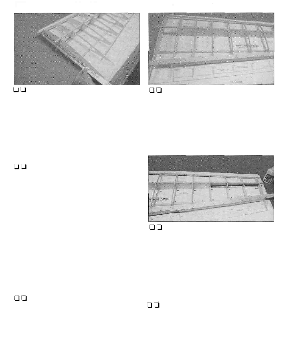
Q Q 16. Glue a 3/32" x 15/16" x 24" balsa TE
sheet to the inner TE and ribs using aliphatic
resin. Note that the sheeting extends from W1
toW7 and is trimmed at an angle. Use your long
straightedge to keepWI straight.
Q Q 17. Glue a 3/32" x 15/16" x 24" balsa TE
sheet to the outer TE and ribs using aliphatic
resin. Note that the sheeting extends from W7
to W12 and is trimmed at an angle. Study the
plan to see how the sheeting is trimmed to fit
the flap tip.
Q Q 15. Prepare the TE that you installed in
steps 10 and 11 for sheeting. Carve and sand the
TE to blend with the top of ribs W1-W12. If you
are not a careful sander you may want to put
some masking tape on the tops of the ribs so
that you won't alter their shape.
[-1L118. Prepare the 1/4" x 1/2" balsa LE that you
installed in step 13 for sheeting. Carve and sand
the LE to blend with the tops of the ribs. Use
masking tape on the ribs so that you don't alter
their shape.
21
Page 22
1—1 19. Glue the leading edge skin that you
prepared in step 2 to the top spar, ribs and LE
using aliphatic resin. The sheeting extends to
the center of the spar.
I-] Q 20. Using 3/32" x 1/4" x 30" balsa, cut, trim
and glue cap strips on the tops of ribsW4 -W12.
Cut the longer pieces first.
Ul Q 21. After the glue has fully dried, remove
the wing from the building board.
Ql [-1 24. Glue the landing gear's 5/8" x 1" x 1"
maple stub block to W2 using 30-minute epoxy.
The block fits into the long cutout in the 1/8" ply
doubler. The groove faces W2.
Q Q 25. Check the fit of the 1/2" x 1" x 8-1/2"
maple landing gear rail in ribsW2,W3 andW4.
When satisfied with the fit, glue it in place with
30-minute epoxy.
Q Q 22. Carve and sand theTE and LE to blend
with the bottom of the ribs as you did in steps
15
and
18.
Q Q 23. Trim the LE and TE sheeting and the
spars even with ribsW1 and W12.
Ql Ql 26. Fit and glue the die-cut 1/8" ply webs
to the front of the landing gear rail using
30-minute epoxy.
22
Page 23
U U 27. Using a 1/4" bit, drill a hole through the
landing gear rail into the stub block. Radius the
top of the hole to fit the bend in the 1/4" landing
gear wire. (See the photo at step 26.)
Q Q 28. Glue a 3/32" x 15/16" x 24" balsa TE
sheet to the bottom of the inner TE and ribs
using aliphatic glue. Note that the sheeting
extends from W1 to W7 and is trimmed at an
angle. Use your straightedge to keep W1
straight.
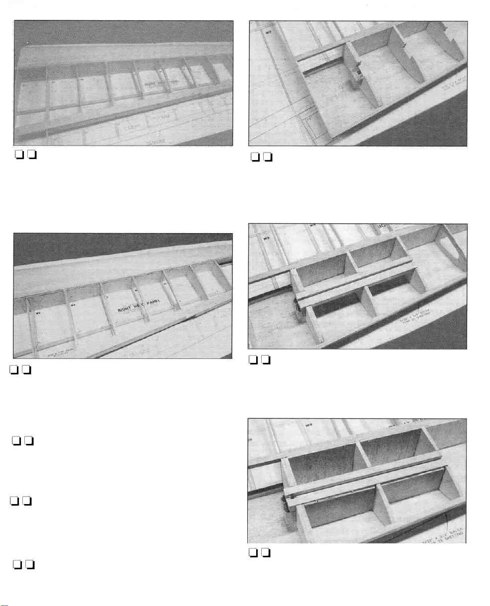
U U 1. Prepare the wing panels for joining by
cutting a 1/16" wide slot in front of and behind
the spars in W1 as shown in the photo.
Q Q 29. Glue a 3/32" x 15/16" x 24" balsaTE sheet
to the bottom of the outer TE and ribs using
aliphatic glue. Note that the sheeting extends
from W7 to W12 and is trimmed at an angle.
Q Q 30.Trim theTE sheeting even with ribsW1
andW12.
Q 31. Return to step one and assemble the left
wing panel.
Q 2.Test fit the die-cut 1/16" ply dihedral braces
to the wing panels. The shorter ply brace goes
on the forward side of the spars. When satisfied
with the fit, glue the braces to left wing panel
with 30-minute epoxy. Remove the right panel
and clean off any epoxy that seeped out from
the joint.
23
Page 24
but it is a bit harder to install this way. Do not
sheet the bottom center section at this time.
Q 6. Glue the die-cut 1/8" ply LE doublers to the
rear of the LE between W1 andW2 on both wing
panels.
[-1 7. Drill two 5/16" holes through the wing LE
and doubler where shown on the plan and in
the photo.
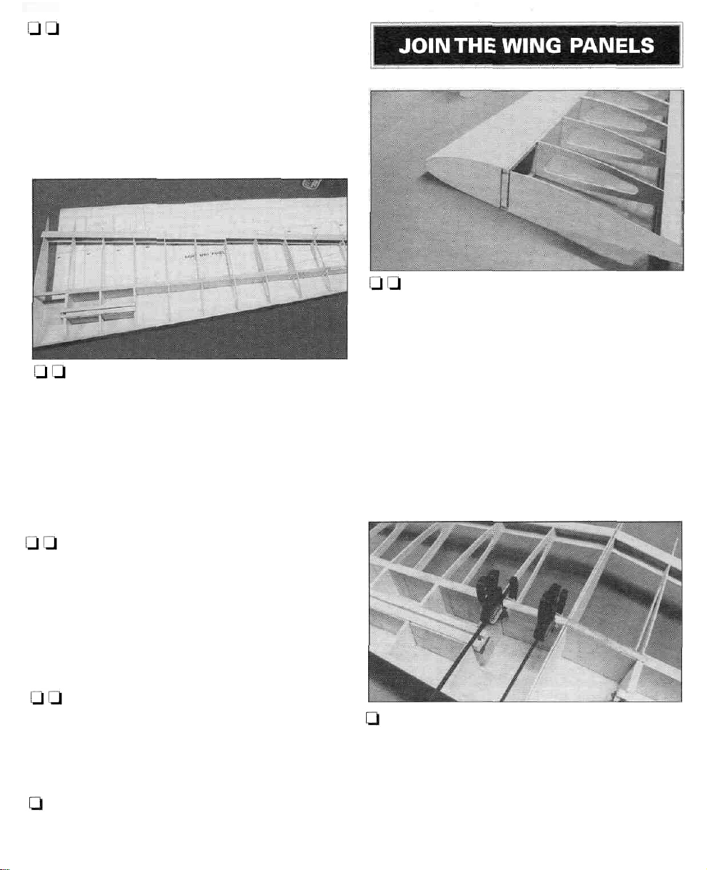
LI 3. After the epoxy has cured, slide the right
panel back into position. Position the right
panel flat on your building board and prop the
left tip off the building board. Don't you wish
your surface was longer!!
Q 4. Measure the distance under the left wing
tip at the bottom of rib W12. If it is 8-3/4" you
have exactly six degrees of dihedral in each
panel. Don't be concerned if it is a little off as
the dihedral angle is not at all critical. If it is off
by more than 1/2" you might want to find out
why, but you don't really need to fix it. When
you are satisfied, glue the dihedral braces to the
right wing panel with 30-minute epoxy. Use
epoxy on theW1 ribs as well.
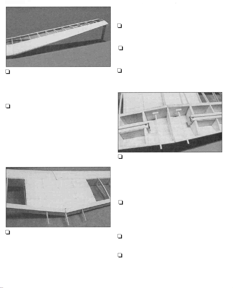
Q 5. Using 3/32" x 3" x 36" balsa, sheet the top
center of the wing from W3 to W3.The strength
of the center section is important so we
recommend that you use aliphatic resin glue.
Note in the photo that we used one continuous
piece across the entire center section rather
than two pieces from W1 to W3 on each side.
This greatly increases the strength of the joint,
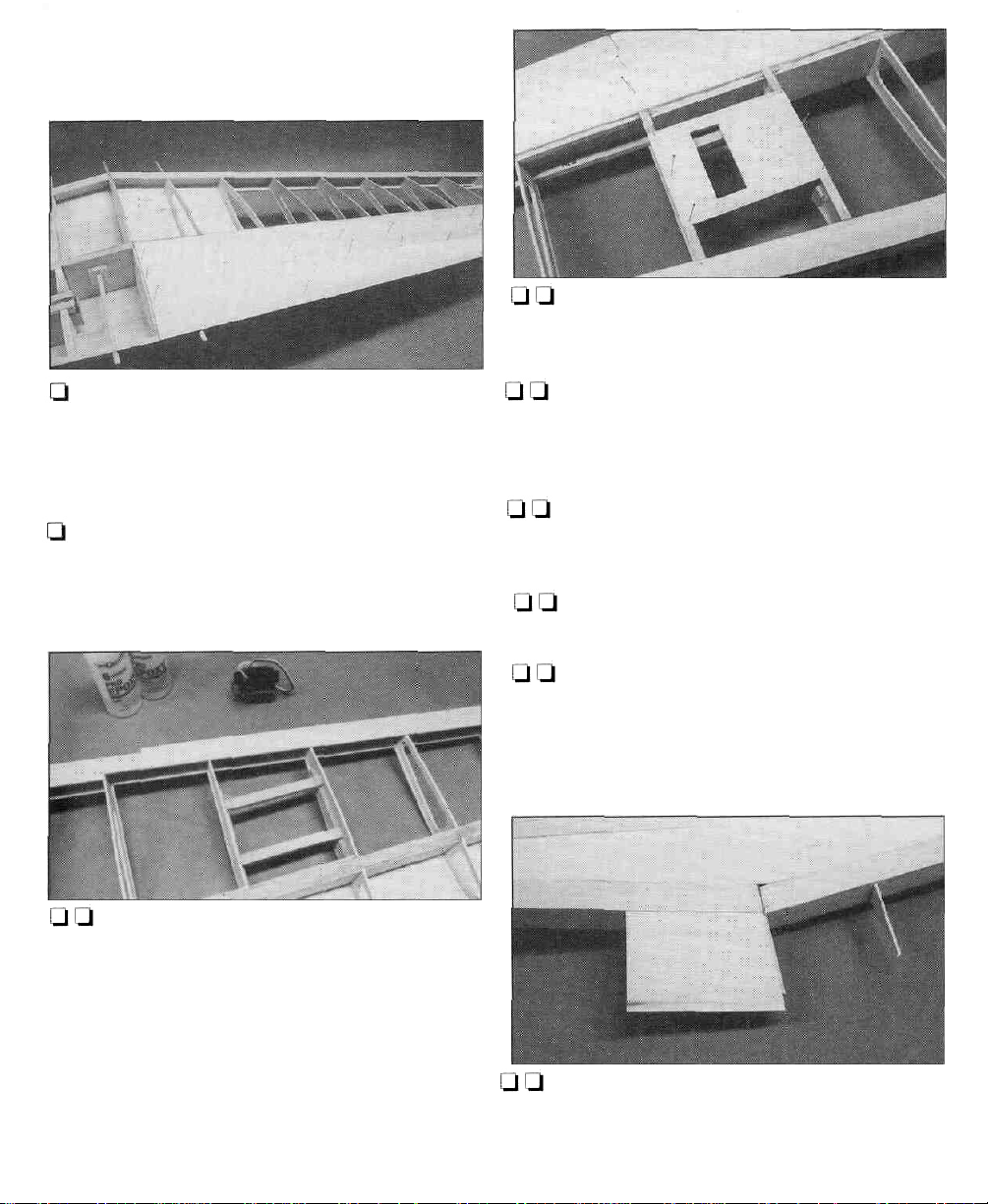
Q 8. Cut two 1/4" x 7/8" x 7/8" balsa blocks from
leftover sticks and drill a 5/16" hole in the center
of both blocks.
Q 9. Slide the 5/16" x 6" wing dowels through
the holes in the LE and put a block on the end of
each dowel. Align the blocks on the 1/16" ply
dihedral braces so that the dowels are parallel
to the wing centerline. Glue the BLOCKS
ONLY to the dihedral braces with 6-minute
epoxy. Remove the dowels before the epoxy sets.
I-] 10. Fit the wing to the fuselage. Center the
wing and mark the location of the dowels on
bulkhead B. This is done by putting a pencil
through the hole in the LE and marking the
bulkhead.
Q 11. Remove the wing and drill 5/16" holes into
bulkhead B.
Q 12. Put the dowels into the wing and fit the
wing back onto the fuselage. Make any
adjustments needed to get the dowels to fit
properly into the holes in bulkhead B. When
24
Page 25
satisfied with the fit, glue the dowels into the
wing with 6-minute epoxy. Use caution not to
get any epoxy on the fuselage.
Q Q 16. Sheet the area around the servo using
leftover 3/32" x 3" balsa.This gives the covering
a place to adhere to.
Q 13. Using the leading edge wing skins you
prepared earlier, sheet the bottom LE of both
wing panels. We find it easiest to use aliphatic
resin on the ribs and medium CA on the spar.
Thin CA can then be used on the LE.
Q 14. Using 3/32" x 3" x 36" balsa, sheet the bottom
center of the wing from W3 to W3. Using one
continuous piece across the entire center-section
will increase the strength of the joint.
Q Q 15. Working on the left wing panel, build
the aileron servo mount between ribs W8 and
W9. Cut two servo mount rails from the 1/4" x
3/8" x 44" basswood shim stick used earlier. Cut
two 3-3/4" long bracing strips from die-cut 1/8"
ply servo rail brace strip. Fit and glue these
pieces into place, spacing the rails to fit the
servo you will be using. Position the rails so the
top of the servo will protrude below the wing
the desired amount.
Oil-] 17. If you are installing flaps on your Chipmunk,
build the flap servo mount between ribsW4 and
W5 as you did above for the aileron servo. Sheet
the area around the servo.
Q l-l 18. Using 3/32" x 1/4" x 30" balsa strips cut,
fit and glue cap strips on the bottom of ribs
W4-W7andW10-W12.
Q t-1 19. Cap strip ribs W8 and W9 where there
is no sheeting.
Q Q 20. Locate a 1-1/2" x 1-5/8" x 9-1/2" balsa
block. Shape the block to the outline of the wing
tip using the plan as a guide. Glue the block
onto tip rib W12. Rough carve and sand the
wing tip block to shape.
l-l l-l 21. Use some leftover 3/32" x 3" sheeting to
cut aTE sheet to go between ribs W1, W2 and
W2A (W2A is added in the next step). Use the
25
Page 26

plan as a guide to cut the sheeting to the proper
size. Glue this piece to the tops of the ribs.
1-1 Q 22. GlueW2A into position. Sand theTE of
the sheeting on the bottom to match the
contour of W1,W2 andW2A.
a Q 23. Cut the 5/8" x 2" x 8-1/2" balsa filler
block to fit between W1 and W2. Glue it into
position. Sand the block to match the contour of
the bottoms ofW1 and W2. (W2A is not shown
in the photo.)
Ui Q 24. Cut anotherTE sheet to shape and glue
it to W1, W2, W2A and the block.
Q Q 3. Cut the LE from 1/4" x 3/4" x 24" balsa.
Sand the bottom of the LE to match the angle of
the aileron ribs at their LE. Glue and pin it to
the
3/32" x 1/2" LE sheet.
I-] l-l 4. Glue ribs A7 -A12 into place.
Q Q 5. From a 1/4" x 1/2" x 36" balsa stick, cut
and glue two horn reinforcement blocks where
the aileron horn will mount.
Q Q 6. Cut and glue hinge blocks into position
from the 1/4" x 1/2" balsa.
Q Q 7. Remove the aileron from the plan. Carve
and sand the top of the LE to match the contour
of the ribs. Taper theTE as well. Be careful as it
is easy to sand into the ribs.
Q25. Return to step 15 for the other wing panel.
Q 26. Rough sand the entire wing.
Ul t-1 1. Cover the right wing panel with Plan
Protector. Cut the bottom LE sheet from 3/32" x
1/2" x 24" balsa and pin it to the plan.
Q Q 2. Cut the bottomTE sheet from 3/32" x 3/4"
x 24" balsa and pin it to the plan.
Q Q 8. Glue the top 3/32" x 1/2" LE sheet into
position.
Q Q 9. Glue the top 3/32" x 3/4" TE sheet into
position. Cut, fit and glue cap strips to the top
and bottom of the aileron ribs using 3/32" x 1/4"
x 30" balsa.
Q Q 10. Fit the die-cut 1/8" ply horn base where
shown on the plan and glue it in place.
i-l Q 11. Sand the Aileron to fit the wing. Mark
the centerline of the aileron leading edge along
its entire length. Using the cross-section on the
plan as a reference, sand the leading edge to
the "V" shape shown. Make sure the "V" is
large enough to allow for the full up and down
movement of the aileron.
26
Page 27

[-I Q 12. Cut four additional hinge blocks from
the 1/4" x 1/2" balsa. Glue these into position in
theTE of the wing opposite the position of the
blocks in the aileron.
Q 13. Return to step one and build the left
aileron.
Note: You must build the flaps even if you will
not be installing working flaps. If you will not be
installing working flaps, simply glue the flaps to
theTE of the wing
Q [-I 7. Remove the flap from the plan. Carve
and sand the top of the LE to match the contour
of the ribs. Taper theTE as well. Be careful as it
is easy to sand into the ribs.
Q Q 8. Glue the top 3/32" x 1/2" LE sheet
into position.
Q Q 9. Glue the top 3/32" x 3/4" TE sheet
into place. Cut, fit and glue cap strips to the top
and bottom of the flap ribs using 3/32" x 1/4"
x 30" balsa.
Q Q 1. Cover the right wing panel with Plan
Protector. Cut the bottom LE sheet from 3/32" x
1/2" x 24" balsa and pin it to the plan.
Q Q 2. Cut the bottom TE sheet from 3/32" x 3/4"
x 24" balsa and pin it to the plan.
Q Q 3. Cut the LE from 1/4" x 7/8" x 24" balsa.
Sand the bottom of the LE to match the angle of
the flap ribs at their LE. Glue and pin it to the
3/32" x 1/2" LE sheet.
Q Q 4. Glue ribs F2 - F7 into place. Note that
there are two F7 ribs.
Ql Q 5. From a 1/4" x 1/2" x 36" balsa stick, cut
and glue two horn reinforcement blocks where
the flap horn will mount.
Q Ql 6. Cut and glue hinge blocks into position
from 1/4" x 1/2" balsa.
Q l_l10. Fit the die-cut 1/8" ply horn base where
shown on the plan and glue it in place.
HINGE
GOES HERE
SAND ANGLE
LJ U 11. Sand the flap to fit the wing. The flaps
are hinged along the bottom of the flap, not
along the centerline as the ailerons were. Sand
an angle along the bottom 1/4" of the flap LE.
Make sure the angle is large enough to allow
for the full down movement of the flap.
27
Page 28

Q Q 12. Cut four additional hinge blocks from
the 1/4" x 1/2" balsa. Glue these into position in
theTE of the wing opposite the position of the
blocks in the flap.
Q 13. Return to step one (1) and build the left flap.
WING
FLAP
FLAP
[-.I 2. Mark the location of the wing bolt plate on
the outside of the fuselage. Mount the wing on
the fuselage and align it squarely to the
fuselage. This is easily done using a piece of
string as a guide. Put a pin in the tail of the
fuselage on the centerline.Tie a loop in one end
of the string and place it over the pin. Move the
other end of the string to one wing tip and put
some masking tape around the string. Draw an
arrow on the tape where it reaches the wing tip.
Now swing the string over to the other wing tip.
If the tip aligns with the arrow the wing is
properly aligned. If not, adjust the wing's
position and try again. Continue to adjust the
wing until both wing tips are aligned with the
arrow on the tape. Secure the wing exactly in
this position.
TRIM ALONG LINE
FROM FLAP CORNERS
Q 1. Mount and align the wing with the fuselage
(see step 2). The center TE sheeting that was
added earlier will need to be trimmed where it
extends past bulkhead DB. Lightly mark the
outline of the fuselage on the top of the wing.
Now mark the location of the front of former DB
on the wing. Remove the wing from the
fuselage. Draw a line on the top of the wing
connecting the aft most corners of the flaps.
Compare this line to the marks you made for
the front edge of former DB. If the line
connecting the corners of the flaps is even with
the marks for former DB, then you are all set.
Trim the wing along this line. If the line does not
line up as above you will need to adjust where
you trim the wing.
Q 3. Drill two pilot holes for the 1/4-20 wing
bolts using a 13/64" bit. Drill the holes through
the wing and into the ply wing bolt plate so that
the holes will be centered fore/aft in the wing
bolt plate.
l-l 4. Remove the wing from the fuselage. Tap
the holes in the ply plate with a 1/4-20 tap. Apply
a couple of drops of thin CA to the threads to
harden them. After the CA has cured, run the
tap through the threads to clean them up.
28
Page 29

Q 5. Fit the two die-cut 1/8" ply wing bolt plates
for the wing bolt holes onto the bottom of the
wing. Glue these into position over the holes with
6-minute epoxy.
l—l 6. Enlarge the wing bolt holes in only the
wing with a 17/64" bit, drilling through the 1/8"
ply plates as well.
I—I 7. Fiberglass both sides of the center of the
wing with 3" tape (included). Put a small patch
around the wing dowels as well.
Q 8. After the fiberglass has dried, put some
Plan Protector on the center of the wing at the
leading and trailing edges where they will touch
the fuselage. Bolt the wing to the fuselage with
the 1/4-20 nylon bolts.
[-I 12. Glue doubler DB to the front of bulkhead
D. Align DB 3/32" above (towards the top of the
fuselage) the TE of the wing to allow for the
3/32" balsa sheeting that will be added to the
bottom of the fuselage.
Q 13. Remove the wing from the fuselage.
Make any adjustments needed to the trailing
edge of the wing where it fits to DB.
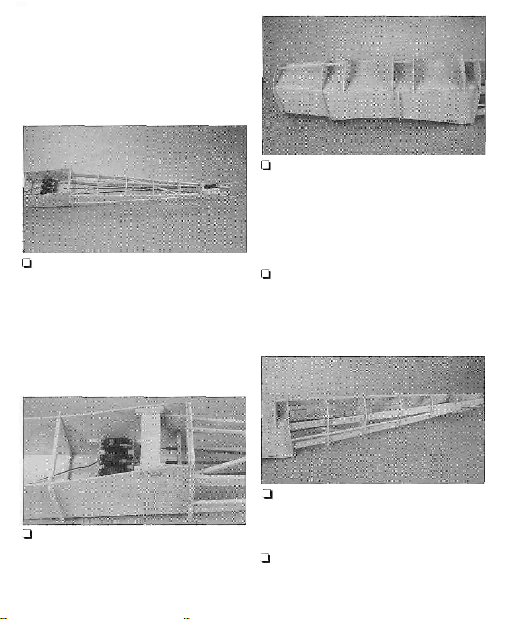
Q 9. Use leftover 1/8" ply to make a bulkhead
for where the leading edge of the wing meets
the fuselage. First fit it to the bottom surface of
the wing, then use a pencil to draw the outline
where it meets the fuselage. Now trim this
bulkhead to shape allowing for the 3/32"
sheeting that will be used to fair the wing with
the fuselage.
Note: The above photo shows how the wing
should look after you finish step 11.
Q 10. Position the bulkhead back on the wing.
When satisfied with the fit, glue it to the
WING ONLY.
Q 11. Cut and fit 3/32" balsa from leftover wing
sheeting to smoothly fair the wing with the fuselage.
Glue the sheeting to the former and wing.
CAUTION: Read and study steps 1-5 before
doing anything!
Q 1. Use the 3/8" x 3/8" x 30" balsa stick to cut,
fit and glue filler strips between formers DB and
EB, EB and FB and between former FB and the
lower longeron on both sides of the fuselage as
shown in the photo. These strips are used as a
place to glue the side sheeting to and also form
a filler block for sanding to shape where the
bottom sheeting meets the side sheeting.
Page 30

SIDE SHEETING 1.1/4"
5"
Q 2. Add a stringer to the fuselage from former
DT to HT. Use the supplied 3/16" x 3/16" x 24"
balsa sticks. Cut notches in top formers DT, ET,
FT, GT and HT, and add a stringer to each side as
shown in the photo above. This will provide a
gluing surface where the top sheeting meets
the side sheeting.
Before sheeting the rear of the fuselage you
should decide what technique you would like to
use. Some modelers prefer to add sheeting in
strips, going from stringer to stringer, one strip
at a time. This requires considerable sanding
once the sheeting has been glued into place.
2-1/2"
13-1/2"
31"
36""
3"
Q 4. If you will be making skins to do the
sheeting, cut and fit the individual pieces from
3/32" x 3" x 36" balsa sheets. Glue them together
and sand them flat and smooth. Make two
skins, one for each side.
Our favorite technique is to fit the individual
sheets and then glue them together flat on your
building board to form a "skin." You can then
sand the skin flat and smooth before it is glued
into position.This requires a bit of finesse when
gluing the skin into place. Use a mix of water
and rubbing alcohol to allow the skin to bend
and conform to the curves more easily. This
technique will give a more consistent shape
and smoother finish.
t-1 3. If you will be sheeting the fuselage one
sheet at a time, sheet the fuselage sides using
the 3/32" x 3"x 36" balsa sheets. Then skip to
step 6.
Q 5. Glue the skin to the fuselage side. Wet the
balsa sheeting with water and alcohol to allow
it to conform to the shape of the sides and
bottom. See the note at step 7.
Q 6. Using some leftover 1/8" sheeting, glue the
small piece of side sheeting into place at
bulkhead D.
30
Page 31

1-1 7. Sand the side sheeting fiat across the 3/8"
x 3/8" filler strips from DB to EB. Sheet the
bottom of the fuselage using 3/32" x 3" x 30"
balsa sheets.
clevis (GPMQ3814) at the rudder end and a 4-40
metal threaded clevis (GPMQ3794) at the servo
end with a 4-40 hex nut.
CJ 11. Fit the horizontal stab to the fuselage. To
do this you will need to cut a slot in the stab for
the rudder torque rod. Cut this slot spanwise as
shown in the photo above. Fit the stab into
position centered on the fuselage centerline.
Pin it into position temporarily.
Note: Notice how the sheeting at the tailwheel
has been cut out to fit the tailwheel bracket.
Q 8. Sheet the top of the fuselage using 3/32" x
3" x 30" balsa sheets.The sheeting extends from
the front most former DT to former I.
D 9. Mount the tailwheel bracket with the wire
tailwheel assembly to the ply tailwheel mount
with #4 x 3/8" sheet metal screws.
Q 10. From the top of the fuselage, install and
connect the rudder pushrod between the
rudder horn and servo. Make sure you install a
clevis retainer and have the linkage properly
adjusted as there is no access to this area after
you finish this section. (Refer to the plans for
the proper installation of the rudder linkage.)
Note: Our prototype model used a 4-40 solid
wire pushrod (GPMQ3718), a 4-40 metal solder
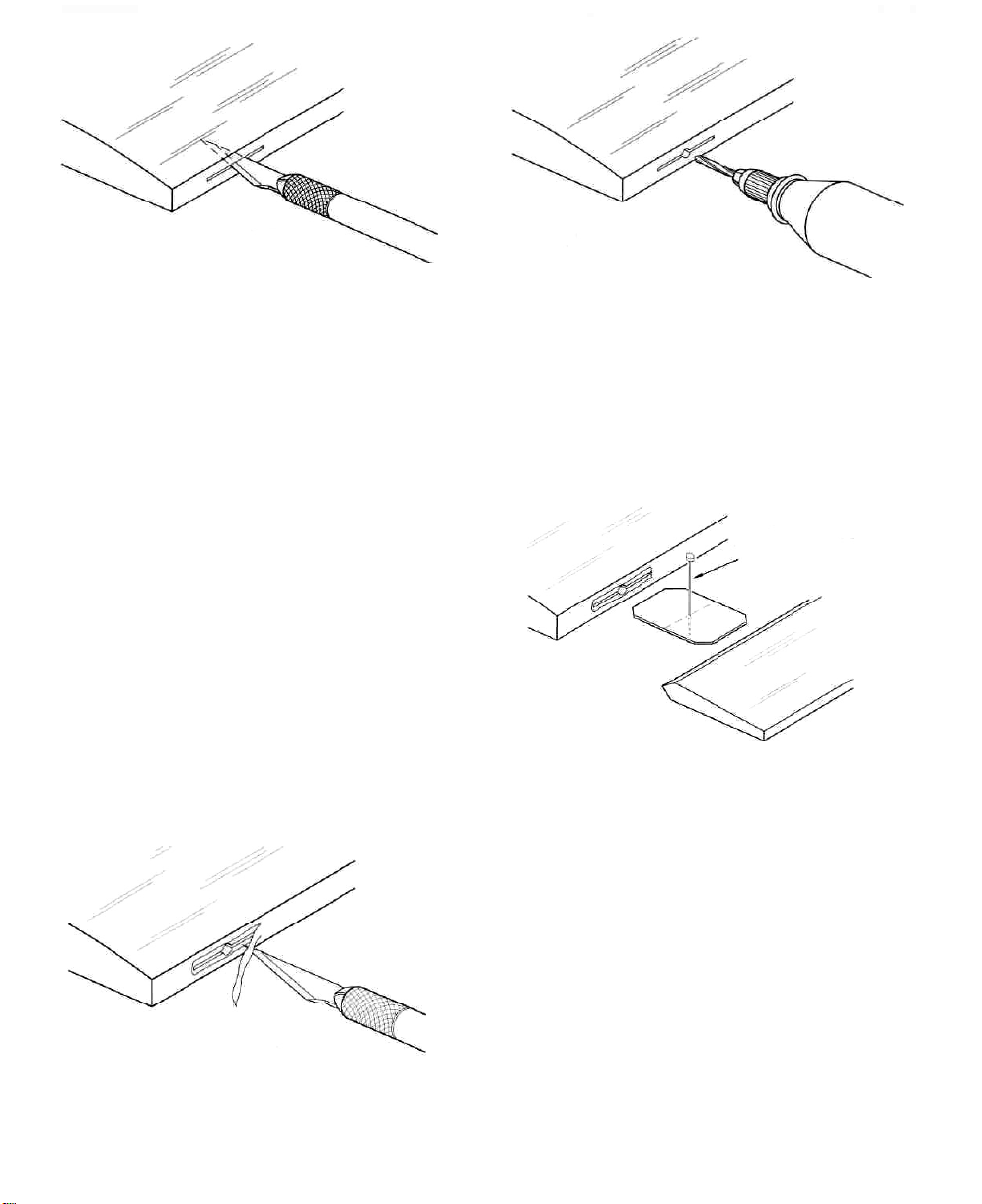
Q 12. Fit the vertical fin to the fuselage.You will
need to cut a slot in the fuselage from former I
forward to former H. Notch former H for the fin
to fit into it.
Q 13. When you are satisfied with the fit of the
stab and fin, remove them from the fuselage.
Glue some leftover 1/4" x 1/2" balsa to the
inside of the top longerons where the stab will
be glued to the fuselage to provide some
additional gluing area.
Q 14. Bolt the wing to the fuselage and set the
assembled wing and fuse on your table. My, my
big isn't it! Maybe you can use the dining
31
Page 32
room table for the next steps. Just make sure to
cover the table so you don't scratch it or get
glue on it, lest - well, you get the idea.
Q 15. Next, you will mount the stab to the
fuselage, but before doing so you need to look
more closely at it. As this is a large model, you
should not depend on glue alone to hold the
stab in place. The plan shows 1/8" dowels that
are keyed into former I. You could also use
some leftover 1/4" x 3/8" basswood glued to the
top of the stab and to former I.
Q 18. When the epoxy has cured remove the
wing. Bring the model back to your workbench
with thanks for the use of the table.
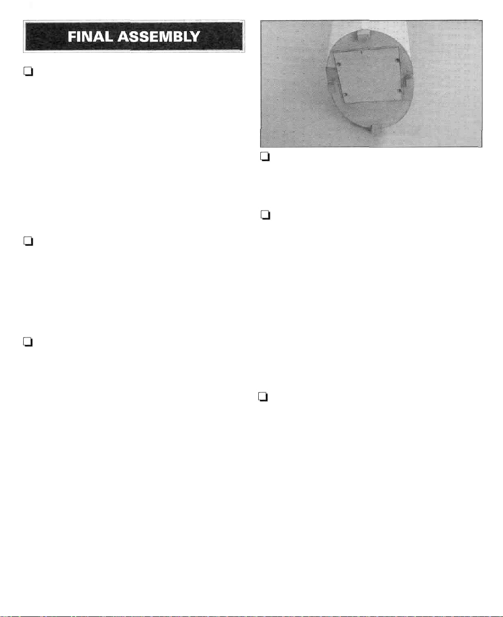
Ol 19. Using the 5/8" x 15/16" x 12" balsa block,
carve and fit a filler block to each side of the fin.
This filler block extends from former I aft and
blends with the bottom of the rudder. Glue it
into position, and then, fill in and blend any areas
that need it with leftover wood and hobby filler.
Q 16. Fit the stab into position and adjust the
stab mount as needed to make the stab parallel
with the wing. Be careful not to change the
incidence angle of the stab. Put a pin in the
nose of the fuselage on the centerline. Use your
string to align the stab just as you did for the
wing. When satisfied with the alignment, glue
the stab in position with 30-minute epoxy.
Q 17. Glue the fin into the fuselage and the top
of the stab with 30-minute epoxy. Be sure the
fin is vertical to the stab and aligned with the
fuselage centerline.
Q 20. Use the 3/16" x 1-1/2" x 18" balsa sheeting
to make a dorsal fin as shown on the plan. Glue
it into position and use filler as needed to blend
it with the fin.
Q 21. Using the 1-5/8" x 2" x 4-3/4" balsa block,
roughly carve and sand the tailcone to shape.
Then, glue it into position.
Now for the final details.
32
Page 33
Q 1. Finish the cockpits. The cockpit area was
designed to be structure free so you can add as
much detail as desired.The simplest is to glue a
couple of Williams Brothers pilots to the top
deck. The kit includes two instrument panel
decals which can be positioned on the front
instrument panel and rear former CT, or you can
fashion separate instrument panels. Details in
the cockpit area will really dress up the
appearance of your model.
Q 2. Install your engine and mount on the
firewall.You should shim your mount as needed
to obtain three degrees of down thrust and two
degrees of right thrust.
Q 3. Fit the cowl. The plastic cowl comes in
halves and needs to be glued together. Before
gluing them, trim them to the proper width.The
kit includes a strip of plastic that is used to
reinforce the joint on the inside. Thin CA works
well for this. When you have glued the cowl
together, cut a small hole where the prop shaft
needs to exit the front. Slip the cowl onto the
fuselage and enlarge the hole as needed to
clear the engine thrust washer. As you continue
to fit the cowl to the fuselage and engine, you
may need to remove and reinstall the engine
several times. We have found that using a piece
of cardboard taped to the side of the fuselage is
the easiest way to locate the cutout for the
engine. Tape the cardboard to the fuselage and
cut an opening in it to fit your engine. Remove
the engine, install the cowl and transfer the
cutout to the cowl. If you go slowly and remove
a little material each time from the cowl, you
will be rewarded with a good looking cowl.
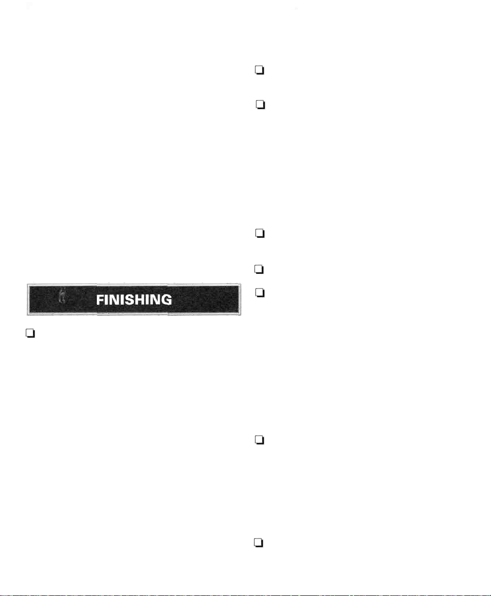
Q 4. When you are satisfied with the fit of the
cowl, remove it and glue the four 1/2" x 1/2"
x 3/4" hardwood blocks into place on the firewall.
Sand them to blend to the curve of the cowl.
Ql 5.To drill the mounting holes in the cowl use
the cardboard technique again. Tape some
cardboard to the fuselage side and mark the
center of the mounting blocks. Slip the cowl
into position and mark the location of the holes,
Drill the holes and mount the cowl with #6 x
1/2" sheet metal screws and washers.
Note: The following describes installing the
hinges for the elevators, ailerons, rudder and
flaps (if installed). It is highly recommended
that you obtain a Great Planes Slot Machine™
(GPMR4010) as it will greatly simplify the
process and make for a better installation.
Q 6. Hinge the control surfaces.The kit includes
a hinge strip from which you can cut CA hinges,
or you can use other hinges of your choice.The
following general guidelines will discuss
hinging. We will discuss hinging the elevator
but the same process is used to hinge the
rudder, ailerons and flaps.
A. If you have not already done so, mark the
centerline of theTE of the stab.
B.The LE of the elevators has already been
sanded to a "V," so this will be used as the
centerline.
C. Using the plan as a reference, mark the
locations of the hinges to be installed.
33
Page 34
CUT HINGE SLOT
WITH HOBBY KNIFE
AND #11 BLADE
D. Use a hobby knife with a #11 blade to
make the hinge slots.The first cut should
be a shallow slit to establish the hinge
slot location. After the first cut make
several more cuts, going slightly deeper
each time. Move the knife from side to
side and widen the slot as you cut.
E. Test join the elevators to the stab with the
hinges in place. DO NOT glue until later.
R Perform the same process for the rudder
ailerons and flaps.
DRILL A 3/32" HOLE
1/2" DEEP, IN CENTER
OF HINGE SLOT
B. Drill a 3/32" hole in the center of all the
hinge slots to allow the CA to fully
penetrate. This is best done with a highspeed tool such as a powered hand tool.
If you use a drill, remove slivers of balsa
wood from the hinge slots with a hobby
knife after you drill the holes.
TEMPORARY PIN
TO KEEP HINGE
CENTERED
AFTER you have completely covered and
finished you model, perform the following:
CUT THE COVERING
AWAY FROM THE SLOT
A. Use your hobby knife and a sharp #11
blade to remove a small strip of covering
from the hinge slots to expose them.
C. Join the elevator to the stab with the
hinges. If the hinges will not stay
centered, insert a pin through the center
of the hinge, then join the surfaces and
remove the pins.
D. Confirm that the ends of the elevator
align with the ends of the stab, that the
hinges are centered and there is
approximately a 1/32" gap between the
TE of the stab and the LE of the elevator.
A small gap is desirable so you do not
inadvertently glue the elevator to the stab
with residual CA.
E. Carefully apply 6 drops of thin CA to each
side of all the hinges. Keep a tissue handy
34
Page 35
to wipe away excess CA. If you spill a few
drops of CA on the MonoKote® film you
can use CA Debonder (GPMR6039) to remove
it. Or wait until the CA fully cures, then
carefully lift it off with a hobby knife blade.
Do not use accelerator on any of the
hinges. Do not glue the hinges with
anything other than thin CA and do not
attempt to glue one half of the hinge at a
time with medium or thick CA. They will
not be secure and the control surfaces
could separate while the model is flying.
F. Let the CA fully cure, then flex the elevator
several times to check the movement.
G. Use the same procedure to hinge the
rudder, ailerons and flaps.
D 1.You may cover and finish your model now
if you desire. We prefer to install the radio
before finishing so we don't add any hanger
rash to our finished model. You may also want
to remove the engine.
Our radio installation consisted of the following:
A. One high torque servo for each aileron.
B. One standard size servo for each flap.
C. One high torque servo for each elevator,
with a separate pushrod for each.
D. One high torque servo for the rudder.
E. One standard size servo for the throttle.
F. We used a 1200 mAh battery pack to
allow for the additional servo drain.
While this is a large aircraft, it does not fly very
fast. We have found that the above installation
has worked very well.
Q 2. If you have not done so already, fuelproof
the engine and tank areas. Final sand the model.
Ul 3. Cover the model. We used Top Flite Super
MonoKote on the prototype model. For the
primary white color (TOPQ0204) we used two
six foot rolls for the wing and one six foot roll
for the fuselage. We used one can of Top Flite
LustreKote® Missile Red (TOPR7201) paint
sprayed directly on the white MonoKote. For
the black anti-glare area in front of the canopy
we used some flat black (TOPQ0508) we had
leftover from an earlier project.
Q 4. After you have finished covering, finish the
hinge installation as covered previously.
Q 5. Finish the cockpit area and install your pilots.
Q 6. Fit the canopy to the fuselage. The canopy
is supplied in two parts; a short front
windscreen area and a larger aft section. On the
full-size aircraft this large aft section would slide
aft for the pilots to enter. To install your canopy,
cut and fit the sections to the fuselage.Trim and
fit the area where the front and aft sections fit
together. Carefully cut the covering where they
will be glued to the fuselage so that the canopy
can be adhered to the wood. Use tape or paint
to detail the frame lines. We used RC-56 glue to
glue the completed canopy to the fuselage.
Q 7. Install your fuel system. We used a 16
tank (GPMQ4107) and a refueling valve
(GPMQ4160). If you are installing a gasoline
engine be sure to use a gasoline compatible
tank, refueling valve and fuel line. We mounted
our tank to the bottom deck on a layer of 1/4"
foam (HCAAIOOO).The tank is held in position
with some leftover 1/4" x 3/8" basswood sticks.
Q 8. Paint the cowl. We usedTop Flite LustreKote
white (TOPR7204), missile red (TOPR7201) and
flat black (TOPR7209).
35
oz.
Page 36
Q 9. Mount the landing gear and 4" wheels
(ROBQ1537).
Note: Optional landing gear struts are available
from Robart that fit this model. These struts not
only add a nice touch to the model but help
absorb landing stresses as well. Complete
instructions from Robart are included.
Ul 10. Mount the control horns to the ailerons,
flaps, elevators and rudder.
Measure the throws at the widest part of the
trailing edge of the rudder, elevator, flaps and
ailerons. After a few flights you may change the
throws to suit your flying style.
We recommend the following control surface
We recommend the following control surface
throws:
throws:
Q 11. Finish the installation of the control
linkages.
Q 12. Install the throttle servo and connect the
linkage to the engine.
Q 13. Final hookups and checks:
A. Take the servo arms off your servos, turn
on your radio and center all of the trims.
Reinstall all the servo arms and secure
them with screws.
B. Make sure that all clevises have a silicone
retainer installed.
Elevator
High Rate
1/2"
Up
Low Rate
3/8"
Up
1/2" Down 3/8" Down
Rudder
Ailerons
Left
2-1/8"
2-1/8"
Right
11/16" Up
1-3/4" Left
1-3/4" Right
1/2"
Up
9/16" Down 7/16" Down
Flaps
1-1/8" Down
Note: We used a Great Planes Accu-Throw™
Deflection Gauge (GPMR2405) to check the control
throws.
Throttle: Set the throttle so that at "high stick" the
carburetor barrel is fully open and at "low stick,"
with full to half throttle trim, the carburetor barrel
is nearly closed. At this position the engine should
run reliably at a low RPM (idle).To shut the engine
off, decrease the throttle trim tab.
C. Make sure that the control surfaces move
in the proper direction.
l-J 14. Identify your model. No matter if you fly
at an AMA sanctioned R/C club site or if you fly
somewhere on your own, you should always
have your name, address, telephone number
and AMA number on or inside your model. It is
required at all AMA R/C club flying sites and
AMA sanctioned flying events.
This section is IMPORTANT and MUST NOT
be omitted. A model that is not properly
balanced
will
be unstable and
possibly
unflyable.
l-l 1. Check the balance point with all components
installed in the model and the fuel tank empty.
Attach the wing to the fuselage, then accurately
mark the balance point on top of both wing
36
Page 37
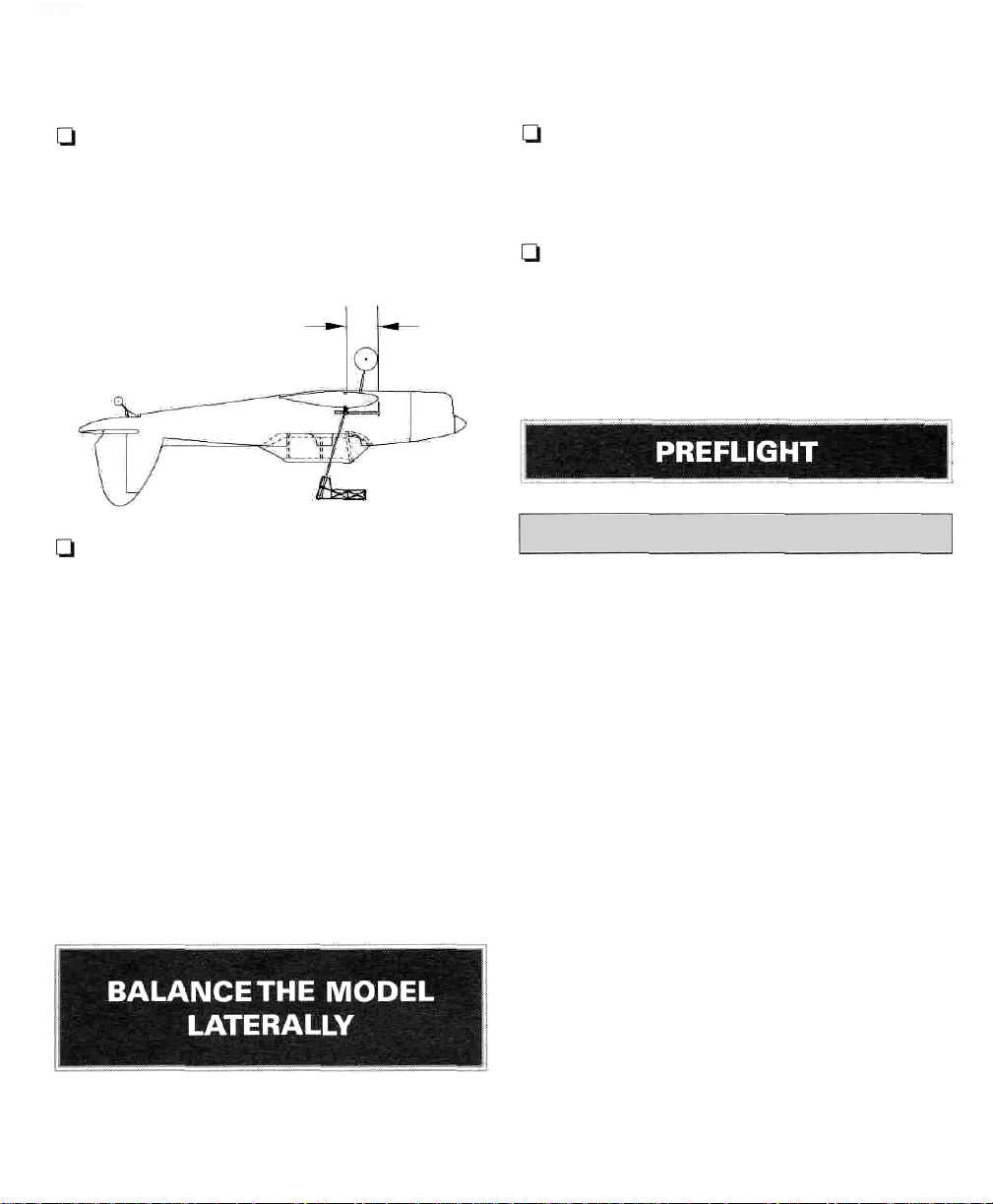
halves next to the fuselage.The balance point is
shown on the plan and is 5-1/2" (140mm) aft of
the leading edge.
Now that the model is covered and nearly
completed, this is the time to balance it laterally
(side-to-side). Here's how:
Q 2. This is the balance point at which your
model should be balanced for your first flights.
Later, you may experiment by shifting the
balance point up to 1/2" (12mm) forward or back
to change the flying characteristics.
5-1/2"
[140mm]
Q 3. Lift the upside-down model with your
fingers at the balance point or use the Great
Planes C.G. Machine'" (GPMR2400). If the tail
drops, shift the receiver and/or battery pack
forward (if possible) to balance the model. If the
nose drops, shift the receiver and/or battery
pack aft. If possible, arrange the battery pack
and receiver to achieve balance but make sure
they remain secure in the fuselage so they
cannot shift during flight or a rough landing. If
you must add additional weight to the nose or
tail of the Chipmunk to achieve balance, use Great
Planes Self Adhesive Lead Weights (GPMQ4485).
An alternative to self adhesive weights (if your
model is tail heavy) is a Great Planes Brass
Spinner Weight (GPMQ4646).
Q 1. With the wing level and attached to the
model (and the engine and muffler installed),
lift the model by the propeller shaft and the fin.
this may require an assistant. Do this several times.
t-1 2. The wing that consistently drops indicates
the heavy side. Balance the model by adding
weight to the other wing tip.
An airplane that is laterally balanced will track
better during aerobatic maneuvers.
ATHOME
Balance your Propellers
Balancing the propeller seems like one of those
things that you can skip, but many problems
are the result of vibration caused by
unbalanced propeller. Nuts and bolts can
vibrate loose and vibration can damage delicate
radio components inside
servos. Vibration can even damage the glow
plug element which could result in an engine
that is difficult or impossible to start. We use a
Top Flite Precision Magnetic Balancer'" (TOPQ5700)
in the workshop and keep a Great Planes
Fingertip Prop Balancer (GPMQ5000)
flight box.
your
receiver
an
and
in our
Do not confuse this procedure with
"checking the C.G"
Charge Your Batteries
Follow the battery charging instructions in the
instruction manual that came with your radio
control system. You should always charge your
batteries the night before you fly.
Ground Check Your Radio
Inspect all nuts, screws and wheel collars. Make
sure you install the screw that holds the servo
37
Page 38

arm onto the servos and the servo cords are
securely connected to the receiver. If you are
not thoroughly familiar with R/C models, ask an
experienced modeler to inspect your radio
installation and make sure the control surfaces
respond correctly.
Note: Failure to follow these safety precautions
may result in severe injury to yourself and others.
The engine must be "broken-in" according to
the engine manufacturer's recommendations
for break-in. Refer to the Engine Safety
Precautions on the next page before you start
your engine. After you run the engine on the
model make sure all screws remain tight, the
hinges are secure and the prop is on tight.
AT THE
Range Check Your Radio
Check the operational range of the radio before
the first flight of each day. Before you turn your
radio on, the first thing you always must do is
make sure no one else is on your frequency
(channel). Most model flying fields utilize
frequency control so familiarize yourself with
their system. Collapse your transmitter antenna
and turn on the transmitter first, then the
receiver (preferably the receiver should never
be on by itself). You should be able to walk at
least 100 feet away from the model and still
have control. Have an assistant stand by your
model and tell you what the control surfaces
are doing while you operate them from the
transmitter.
FLYING
SITE
Store model fuel in a safe place away from high
heat, sparks or flames. Do not smoke near the
engine or fuel as it is very flammable. Engine
exhaust gives off a great deal of deadly carbon
monoxide so do not run the engine in a closed
room or garage.
Get help from an experienced modeler when
you learn to operate engines.
Use safety glasses when you operate model
engines.
Do not run the engine near loose gravel or
sand; the propeller may throw loose material in
your face or eyes.
When you start and run the engine keep your
face and body as well as all spectators away
from the plane of rotation of the propeller.
Always be aware and very conscious of hand
movements and be deliberate in your reach for
the needle valve, glow plug clip, or other items
near a spinning propeller.
Keep loose clothing, shirt sleeves, ties, scarfs,
long hair or loose objects away from the prop.
Be conscious of pencils, screwdrivers or other
objects that may fall out of your shirt or jacket
pockets.
Repeat this test with an assistant holding the
model and the engine running at various
speeds. If the control surfaces do not always
respond correctly, do not fly! Find and correct
the problem first. Look for loose servo
connections or corrosion, loose fasteners that
may cause vibration, a defective on/off switch,
low battery voltage or a defective cell, a damaged
receiver antenna or a receiver crystal that may
have been damaged from a previous crash.
Use a "chicken stick" or electric starter and
follow the instructions to start your engine.
Make certain the glow plug clip or connector is
secure so that it will not pop off or get into the
running propeller.
Ask an assistant to hold the model from the rear
while you start the engine and operate the
controls.
38
Page 39
Make all engine adjustments from behind
rotating propeller.
The engine gets hot! Do not touch the engine
during or immediately after you operate it.
Make sure fuel lines are in good condition so
fuel will not leak onto a hot engine and cause
a fire.
the
9. I will not operate models with pyrotechnics
(any device that explodes, burns, or propels a
projectile of any kind).
RADIO CONTROL
1. I will have completed a successful radio
equipment ground check before the first flight
of a new or repaired model.
To stop the engine, close the carburetor barrel
(rotor) or pinch the fuel line to discontinue the
fuel flow. Do not use your hands, fingers orany
body part to stop the engine. Never throw
anything into the prop of a running engine.
Read and abide by the following Academy of
Model Aeronautics Official Safety Code:
GENERAL
1. I will not fly my model aircraft in sanctioned
events, air shows, or model flying demonstrations
until it has been proven to be airworthy by
having been previously successfully flight tested.
2. I will not fly my model aircraft higher than
approximately 400 feet within 3 miles of an
airport without notifying the airport operator. I
will give right of way to and avoid flying in the
proximity of full-scale aircraft. Where necessary
an observer shall be used to supervise flying to
avoid having models fly in the proximity of
full-scale aircraft.
3. Where established, I will abide by the safety
rules for the flying site I use and I will not
willfully and deliberately fly my models in a
careless, reckless and/or dangerous manner.
7. I will not fly my model unless it is identified
with my name and address orAMA number, on
or in the model.
2. I will not fly my model aircraft in the presence
of spectators until I become a qualified flier,
unless assisted by an experienced helper.
3. I will perform my initial turn
away from the pit or spectator areas and I will
not thereafter fly over pit or spectator areas,
unless beyond my control.
4. I will operate my model using only radio
control frequencies currently allowed by the
Federal Communications Commission.
after
takeoff
FIND A SAFE PLACE TO FLY
The best place to fly your R/C model is an AMA
(Academy of Model Aeronautics) chartered club
field. Ask your hobby shop dealer if there is
such a club in your area and join. Club fields are
set up for R/C flying which makes your outing
safer and more enjoyable.The AMA can also tell
you the name of a club in your area. We
recommend that you join the AMA and a local
club so you can have a safe place to fly and also
have insurance to cover you in case of a flying
accident. (The AMA address is listed on page 3
of this instruction book.)
If a club and its flying site are not available, you
need to find a large, grassy area at least 6 miles
away from any other R/C radio operation and
away from houses, buildings and streets. A
schoolyard may look inviting but it is usually
39
Page 40

too close to people, power lines and possible
radio interference. If you are a beginner, you
are busy enough concentrating on your model
without having to answer lots of questions and
performing crowd control.
We highly recommend that you get an
experienced modeler to assist you with your
flight training. An experienced modeler can
take your Chipmunk up for the first time and
make sure it performs correctly, then give you
valuable flight instruction. He can hand you the
transmitter when the Chipmunk has climbed to
a safe altitude or connect your transmitter to his
if both of your systems have trainer cord or
"buddy box" capability. Assistance from an
experienced modeler will make your modeling
"career" progress faster (and cheaper). We do,
however, realize that some modelers are
determined to learn on their own or are not in a
location where an instructor or flying club is
available. Therefore, we have provided the
following information to give you an idea of
what to expect on your first flight with your
Chipmunk. Both flyers who plan to set out on
their own and fliers who will have the help of
an instructor should carefully read the
following information.
TAKEOFF
First flight attempts should be reserved for ca Im
days when the wind speed is less than five
mph. Always takeoff (and land) into the wind.
Check the operation of all controls just before
takeoff. This will eliminate the possibility of
overlooking reversed or disconnected controls
(it happens). Your Chipmunk is a model of the
full-size aircraft, used mainly as a training
aircraft. The full-scale aircraft is a low powered,
gentle and forgiving aircraft. Your model flies
much like the aircraft it is modeled after. It
performs in a very scale-like manner with the
recommended engines. Do not expect it to fly
like sport models you may have previously flown.
As you apply power on takeoff you will need to
apply a slight amount of right rudder to
compensate for engine torque and propeller
"P" effect. The tail will rise almost immediately,
indicating that the tail surfaces have gained
effectiveness. Allow the model to continue to
accelerate until it has reached flying speed. Use
as much of the available runway as you can.
Then, gently apply some up elevator. Your
Chipmunk should slowly lift from the runway.
Continue straight ahead until you have
accelerated to a safe flying speed. Make your
first turn away from the spectator and pit area.
FLIGHT
The full-size Chipmunk was designed to teach
takeoffs, landings, turns, stalls, spins and gentle
aerobatics. Being relatively low powered, it
does not have a high rate of climb and has poor
vertical performance. To gain airspeed for a
loop it was necessary to dive for a brief period.
Barrel rolls were slow, teaching roll coordination.
If you fly your model in the same manner you
will be very pleased with its performance.
Before attempting your first landing you should
first try some slow flight and stalls to become
familiar with the Chipmunk's slow speed
characteristics.You will probably find the model
slows down quicker and requires more power
than you are used to. Expect to carry some
power on final approach, especially if you are
using flaps. The model will quickly lose speed
with a nose high attitude on final approach.
Remember that aircraft of the Chipmunk's era
had limited low speed control effectiveness,
especially for the ailerons. The rudder is very
effective, however. Continue to carry power and
speed until you initiate the flare, then reduce
power and allow the model to gently settle to
the ground. If you must go around, add power
and accelerate straight ahead. Do not attempt
to climb, turn or raise the flaps until you have
accelerated to a safe flying speed.
We hope you enjoy the realistic looks and
performance of your Chipmunk.
40
Page 41
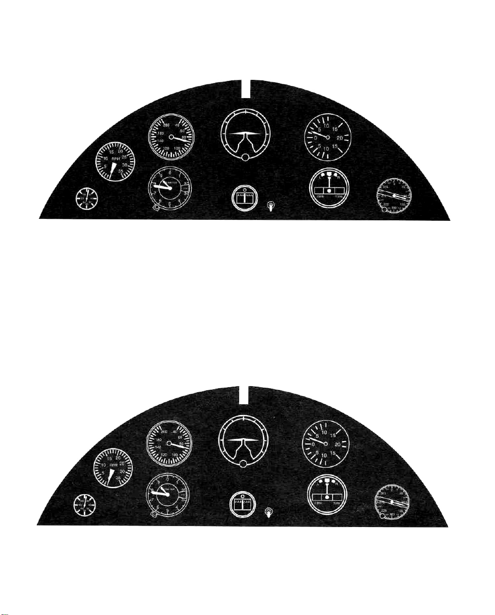
Center Pull
Page 42

TWO VIEW DRAWING
Use copies of this page to plan your trim scheme
-Out Page
 Loading...