

Page 1
FLYBP03 for DYFA3030 Printed in USA
READ THROUGH THIS INSTRUCTION MANUAL FIRST. IT CONTAINS
IMPORTANT INSTRUCTIONS AND WARNINGS CONCERNING THE ASSEMBLY
AND USE OF THIS MODEL.
Entire Contents © Copyright 1997
Instruction Manual
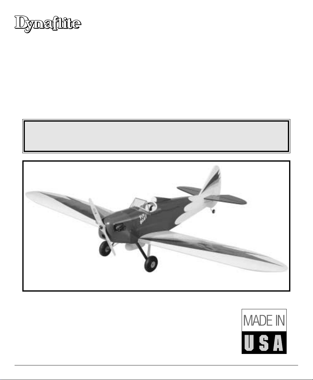
• REALISTIC FUN SCALE MODEL
• HUGE, 84” WINGSPAN (IMAA Legal)
• 1/4 SCALE MODEL • BUILDS QUICKLY
WARRANTY
Dynaflite guarantees this kit to be free from defects in both material and workmanship at the date of
purchase. This warranty does not cover any component parts damaged by use or modification. In no
case shall Dynaflite's liability exceed the original cost of the purchased kit. Further, Dynaflite reserves
the right to change or modify this warranty without notice. In that Dynaflite has no control over the
final assembly or material used for final assembly, no liability shall be assumed nor accepted for any
damage resulting from the use by the user of the final user-assembled product. By the act of using
the user-assembled product, the user accepts all resulting liability. If you are not prepared to accept
the liability associated with the use of this product, return this kit immediately in new and unused
condition to the place of purchase.
™
™
88
88
44
44""""
FF
FF
uu
uu
nn
nn
SS
SS
cc
cc
aa
aallll
ee
ee
FF
FFllll
yy
yy
BB
BB
aa
aa
bb
bb
yy
yy
Page 2

Introduction........................................................2
Precautions.........................................................3
Preparations.......................................................4
Required Items ..................................................4
Optional Items ..................................................4
Suggested Supplies ...........................................4
Building Notes ..................................................5
Types of Wood..................................................5
Metric Conversions............................................5
Die Patterns ...................................................6&7
Build the Tail Group ............................................8
Build the Fin......................................................8
Build the Rudder................................................8
Build the Stabilizer ............................................9
Build the Elevators.............................................9
Build the Wing....................................................9
Join the Wing Halves.......................................14
Build the Ailerons............................................16
Build the Fuselage.............................................16
Final Assembly .................................................20
Finishing ..........................................................24
Set the Control Throws......................................25
Balance the Model............................................26
Preflight ...........................................................26
At Home..........................................................26
At The Flying Site .............................................26
Engine Safety Precautions .................................27
Flight................................................................27
Find a Safe Place to Fly.....................................27
Takeoff................................................Back Cover
Flying .................................................Back Cover
Landing...............................................Back Cover
Congratulations on your choice of this kit for your
next project. The Fly Baby is a Fun Scale™model of
a true classic aircraft. It has the presence that only a
big model can carry off. The full scale Fly Baby was
actually derived from a model aircraft. This kit is a
model of that full scale aircraft.
The Dynaflite Fly Baby was designed to allow the
modeler a wide selection of power plants from a .75
two stroke to a 25 cc gas engine. With an airplane
this large and a power plant selection this broad,
there are a few problems that may come up. If you
use a light .75 two stroke you will need to add
weight to the nose. A .91 4 stroke will balance very
closely. With a gas motor like the US Engines 25cc
you will need to add weight in the tail.
At Dynaflite we take pride in offering kits that are
simple and straightforward to build and provide
value for your modeling dollar. Because of the size
and cost of this model, we assume you have built
several models and have a general working
knowledge of modeling and its terms.
If you HAVE NOT built and flown several kits, do
yourself a favor - back up and get some experience
before beginning this kit.
Please inventory and inspect all par ts carefully
before starting to build! If any par ts are missing,
broken or defective or if you have any questions
about building or flying this model, please call us at
(217) 398-8970 and we'll be glad to help. If you are
calling for replacement parts, please look up the
part numbers and have them ready when calling.
INTRODUCTIONTABLE OF CONTENTS
2
Page 3
3
Your Fly Baby is not a toy, but a sophisticated working
model that functions like a full-size airplane. Because
of its performance, if you do not assemble and
operate the Fly Baby correctly, you could possibly
injure yourself or spectators and damage property. To
make your R/C modeling experience totally
enjoyable, we recommend that you get assistance
with assembly and your first flights from an
experienced, knowledgeable modeler. You'll learn
faster and avoid risk to your model before you're
truly ready to solo. Your local hobby shop has
information about flying clubs in your area whose
membership includes qualified instructors.
You can also contact the national Academy of Model
Aeronautics (AMA), which has more than 2,500
chartered clubs across the country. We recommend
you join the AMA which will provide you with
insurance coverage at AMA club sites and events.
AMA Membership is required at chartered club
fields where qualified flight instructors are available.
Contact the AMA at the address or toll-free phone
number below.
Academy of Model Aeronautics
5151 East Memorial Drive
Muncie, IN 47302
(800) 435-9262
Fax (765) 741-0057
1. You must assemble the plane according to the
instructions. Do not alter or modify the model, as
doing so may result in an unsafe or unflyable model.
In a few cases the instructions may differ slightly
from the photos or plan. In those instances the text
should be taken as correct.
2. You must take time to build straight, true and strong.
3. You must install all R/C and other components so
that the model operates properly on the ground and
in the air.
4. You must test the operation of the model before the
first and each successive flight to insure that all
equipment operates correctly. You must also make
certain that the model has remained structurally sound.
NOTE: We, as the kit manufacturer, provide you
with a quality kit and great instructions, but
ultimately the quality and flyability of your finished
model depends on how you assemble it; therefore,
we cannot in any way guarantee the performance
of your completed model and no representations
are expressed or implied as to the performance or
safety of your completed model.
PRECAUTIONS
PROTECT YOUR MODEL,
YOURSELF & OTHERS...
FOLLOW THIS IMPORTANT
SAFETY PRECAUTION
Page 4
These are the items “not included“ with your kit; you
will need to purchase them separately. Items in
parentheses (GPMQ4107) are suggested part
numbers recognized by distributors and hobby
shops and are listed for your ordering convenience.
GPM is the Great Planes®brand, TOP is the Top
Flite®brand and HCA is the Hobbico®brand.
❏ 4 channel radio with 6 servos
(5 high torque to be IMAA legal)
❏ Engine - .75 to .90 2-stroke
.91 to 1.20 4-stroke or 25cc gas
❏ Engine mount and mounting hardware
❏ 16 oz. Fuel tank, 2 or 4-stroke (GPMQ4107)
❏ 20 oz. Fuel tank, gas (DUBQ0220)
❏ Gas stopper (DUBQ0675)
❏ Standard fuel tubing, 2 or 4-stroke (GPMQ4131)
❏ Tygon fuel tubing, gas (AERQ2125)
❏ (2) 4-1/2" Main wheels (DUBQ0846)
❏ (1) 1-1/2" Tail wheel (GPMQ4243)
❏ (4) 1/4" Wheel collars (DUBQ1200)
❏ (2) 3/32" Wheel collars (GPMQ4302)
❏ Coverite
™
Fabric covering – Main color one
15’ roll – Trim colors one 6’ roll per color
❏ Paint for fuelproofing and engine cowl
❏ (1) 1/4 Scale pilot (DGAQ2110)
❏ 1/4" Latex Foam Rubber (HCAQ1000)
❏ (2) 12" Servo extension wires (ailerons)
❏ (2) ‘Y’ Connectors (ailerons, elevators)
❏ (2) 24" Servo extension wires (gas only)
❏ Cockpit and Accessory Kit (DYFQ8110)
We recommend Great Planes Pro™CA and Epoxy
❏ 4 oz. Thin CA Adhesive - (GPMR6004)
❏ 4 oz. Medium CA Adhesive (GPMR6010)
❏ 2 oz. Thick CA Adhesive - (GPMR6015)
❏ CA Accelerator - (GPMR6035)
❏ CA Applicator Tips - (HCAR3780)
❏ 6-Minute Epoxy - (GPMR6045)
❏ 30-Minute Epoxy - (GPMR6047)
❏ 4 oz. Aliphatic Resin Glue (GPMR6161)
❏ 4 oz. Milled Fiberglass (GPMR6165)
❏ Microballoon Filler (TOPR1090)
❏ J & Z Products RC/56 Canopy Glue
(JOZR5007)
❏ Great Planes Plan Protector (GPMR6167)
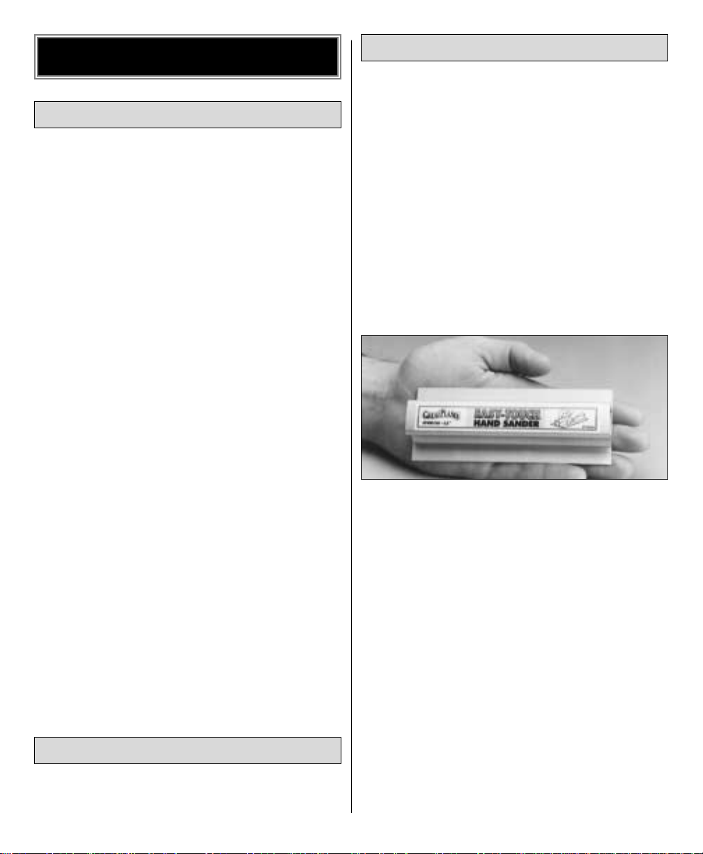
A flat, durable, easy-to-handle sanding tool is a
necessity for building model airplanes. Great Planes
makes a complete range of Easy-Touch™Bar Sanders
and replaceable Easy-Touch adhesive-backed
sandpaper. For future reference, here's a list of
Easy-Touch Bar Sanders and adhesive-backed
sandpaper:
5-1/2" Bar Sander (GPMR6169)
11" Bar Sander (GPMR6170)
22" Bar Sander (GPMR6172)
33" Bar Sander (GPMR6174)
44" Bar Sander (GPMR6176)
Assortment pack of 5-1/2" strips (GPMR6189)
Adhesive-backed 12' roll of:
80-grit (GPMR6180)
150-grit (GPMR6183)
180-grit (GPMR6184)
220-grit (GPMR6185)
Use 320-grit wet-or-dry sandpaper for finish sanding.
SUGGESTED SUPPLIES
OPTIONAL ITEMS
REQUIRED ITEMS
PREPARATIONS
4
Page 5
5
• When you see the term “cut and fit” in the
instructions, it means you should first position the
part on the assembly without using any glue.
Slightly modify or shape the part as necessary
for the best fit.
• Whenever just “epoxy” is called for, you may
use
either
30-minute epoxy or6-minute epoxy.
When 30-minute epoxy is specified, it is highly
recommended that you use only 30-minute
epoxy because you will need either the working
time or the additional strength.
• During construction you will be using a number of
balsa sticks to frame various assemblies. Ample
material is included but you should study the plans,
then make an effort to cut the longest pieces you
will need first. Label the pieces for later reference
as you cut them. By doing this now, you won’ t have
to splice pieces together later.
• Do not throw away any leftover material until
after you have completed your model. Some
small pieces of leftover balsa or plywood are
used during construction.
• This kit is built with three types of glue.
Cyanoacrylate - CA glues cure almost instantly
and are moderately strong. There are three
common types used: thin, medium and thick.
Thin cures the fastest but will not span gaps
between parts. Medium and thick are used
where parts do not fit perfectly. CA glue does not
bond well to most plywoods and hardwoods. CA
glues are also brittle.
Aliphatic Resin - Resin glues require that parts be
pinned or clamped together while the glue
dries–typically 15 - 30 minutes. Resin glues
are very strong and work well with balsa
and plywoods.
Epoxy - 6-minute epoxy cures the fastest; it sets
within six minutes but is not fully cured for one
hour or more. 30-minute epoxy is the strongest
as it allows the epoxy to soak into the wood
thoroughly. While it sets within 30 minutes, it is
not fully cured for two or more hours.
Throughout the assembly of this model, THIN CA
should be used unless the step calls for another
type of adhesive. If your parts do not fit well,
substitute MEDIUM or THICK CA.
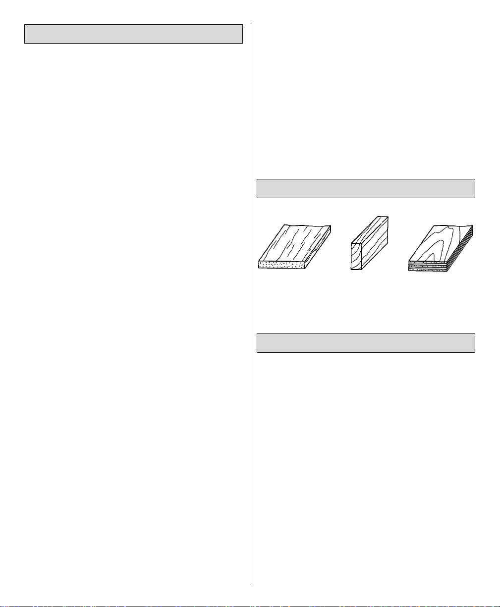
BALSA BASSWOOD PLYWOOD
1" = 25.4mm (conversion factor)
METRIC CONVERSIONS
TYPES OF WOOD
BUILDING NOTES
1/64" = .4mm
1/32" = .8mm
1/16" = 1.6mm
3/32" = 2.4mm
1/8" = 3.2mm
5/32" = 4mm
3/16" = 4.8mm
1/4" = 6.4mm
3/8" = 9.5mm
1/2" = 12.7mm
5/8" = 15.9mm
3/4" = 19mm
1" = 25.4mm
2" = 50.8mm
3" = 76.2mm
6" = 152.4mm
12" = 304.8mm
15" = 381mm
18" = 457.2mm
21" = 533.4mm
24" = 609.6mm
30" = 762mm
36" = 914.4mm
Page 6
6
DIE-PATTERNS
Page 7
7
DIE-PATTERNS
Page 8
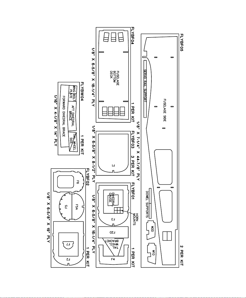
❏ 1. Place the fin and rudder plan on your work
surface and cover it with wax paper.
❏ 2. From the 3/8"x 15/16"x 36" balsa stick cut,
fit and glue the fin TE and fin upper bottom piece
(shaded area on plan).
❏ 3. From a 3/8"x 5/8"x 30" balsa stick cut, fit
and glue the fin lower bottom piece (shaded area
on plans).
❏ 4. From a 3/8"x 5/8"x 30" balsa stick cut, fit
and glue the fin LE.
❏ 5. From a 1/8" x 3/8" x 24" balsa stick cut, fit
and glue the fin ribs in place.
NOTE: It is important that the ribs fit the LE and TE
well. It is not important that each rib fit the exact
location shown on the plan.
❏ 6. Use leftover 3/8" x 15/16" balsa to cut and
glue the gusset between the Fin LE and Fin Bottom.
❏ 7. Sand both sides of the fin flat. Radius the LE as
shown on the plan.
❏ 1. Laminate the two 1/8" die-cut rudder TE1
pieces together. Do the same for the TE2 pieces.
Glue the TE1 and TE2 pieces together over the plan.
After they are dry remove them from the plan.
❏ 2. Laminate three 1/8" die-cut rudder base
pieces together.
❏ 3. Pin three 1/16" balsa shims in place over
the plans.
❏ 4. From a 3/8"x 5/8"x 30" balsa stick, cut and
pin the rudder leading edge in place. Glue the
rudder base to the LE.
❏ 5. Making sure to keep the TE against the 1/16"
shims, glue it to the rudder base and the LE.
❏ 6. From the remainder of the 1/8"x 3/8"x 24"
balsa stick, cut, fit and glue the rudder ribs in place.
NOTE: It is important that the ribs fit the LE and TE
well. It is not important that each rib fit the exact
location shown on the plan.
❏ 7. From the 3/8"x 3/8"x 24" balsa stick, fit and
glue the three hinge blocks in place.
❏ 8. Sand this assembly to the airfoil shown in the
cross section on the plan.
BUILD THE RUDDER
BUILD THE FIN
BUILD THE TAIL GROUP
8
Page 9
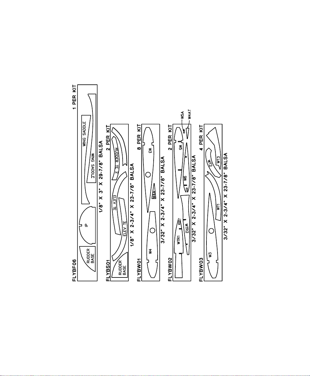
❏ 1. Place the stab and elevator plan on your work
surface and cover it with wax paper.
❏2. From the 3/8"x 5/8"x 36" balsa stick, cut and
glue the stab TE and sub TE together. Pin it in place
on the plan.
❏3. From the remainder of the 3/8" x 15/16" balsa
stick used for the fin, make two stab center pieces.
Glue them in place making sure to use two 3/8"
shims so that the fin bottom will fit into the stab center.
❏ 4. From a 3/8"x 5/8"x 30" balsa stick, cut and
glue the stab LE in place.
❏ 5. Using a leftover piece of 3/8"x 15/16" balsa
stick, fit and glue the stab tip gussets in place.
❏ 6. From a 1/8"x 3/8"x 24" balsa stick, cut, fit
and glue the stab ribs in place.
NOTE: It is important that the ribs fit the LE and TE
well. It is not important that each rib fit the exact
location shown on the plan.
❏ 7. Using the remainder of the 3/8"x 3/8" balsa
stick, cut and glue the hinge blocks in place.
❏ 8. Sand both sides of the stab flat. Radius the LE
as shown on the plan.
❏ 1. Laminate two of the 1/8" die-cut balsa elevator
trailing edge pieces together for each elevator.
❏❏2. From a 3/8"x 5/8"x 30" balsa stick, cut the
elevator leading edge and also the root end of the
elevator. Glue these pieces together over the plan.
❏❏3. Holding the laminated TE down on the
1/16" balsa shims, glue it to the TE and root.
❏❏4. From a 1/8"x 3/8"x 24" balsa stick, cut,
fit and glue the elevator ribs in place.
NOTE: It is important that the ribs fit the LE and TE
well. It is not important that each rib fit the exact
location shown on the plan.
❏❏5. From the remainder of the 3/8" x 3/8"
balsa stick, cut and glue the hinge blocks into place.
❏❏6. Sand this assembly to the airfoil shown in
the cross section on the plan.
NOTE: This is a semi symmetrical wing. Make sure
you mark the top of the ribs so that you get them all
correctly positioned.
❏ 1. Remove the ribs from the die sheets. Mark the
top of the ribs with a pen.
BUILD THE WING
BUILD THE ELEVATORSBUILD THE STABILIZER
9
Page 10

❏ 2. Glue the die-cut 1/8" ply W1D and W2D
doublers to four W3 ribs with 6-minute epoxy as
shown in the photo.
NOTE: The W1D landing gear notch is deeper than
the notch in W2D.
❏❏3. Cover the left wing plan with wax paper.
Pin the 1/4" x 3/8" x 36" basswood bottom spar
into place. Pin the 1/4" x 3/8" x 36" balsa building
jig into place with the 1/4" side against the plan.
NOTE: In the following steps pin the rear of each rib
to the 1/4" x 3/8" building jig as they are glued to
the spar.
❏❏4. Glue the center rib into place using the
dihedral gauge to set the angle. Make sure the W1D
doubler is toward the tip of the wing.
❏❏5. Glue the rib with the W2D rib doubler onto
the bottom spar. Make sure the W2D doubler is
toward the root of the wing.
❏❏6. Glue the remaining W3 and W4 ribs to the
spar keeping them 90 degrees to the work surface
and aligned over the ribs on the plans.
NOTE: Do not glue ribs W5 and W6 at this time.
❏❏7. Glue the 1/4" x 3/8" x 36" basswood top
spar into place.
❏❏8. From a sheet of 3/32" x 4" x 36" balsa cut
and glue the shear webs into place.
IMPORTANT: Do not put shear webs between ribs
W1 and W2 or between W2 and the first W3 on
the front of the spars.
❏❏9. Fit together but do not glue W5, W6,
WTR1, and WTR2
❏❏10. Cut and pin two 1/2" shims and one
3/4" shim in place.
❏❏11. Trim the top and bottom spars even with
the tip side of W5.
10
Page 11

11
❏❏12. Glue WTR1 and W5 to the spars keeping
WTR1 down against the 1/2" shim. It will be
necessary to squeeze and hold the spars together
until the glue cures.
❏❏13. Glue WTR1 to rib W6 and WTR2 to ribs
W4, W5 and W6, making sure to keep the wing tip
down against the shims.
❏❏14. Cut a 18-5/8" long piece from a 1/4" x
3/4" x 24" balsa stick and glue it to the last W3 rib,
W4 ribs and the W5 rib. Keep rib W5 centered on
the TE.
❏❏15. Sand the TE to the shape shown on the
plan. Remove the wing from the building surface to
shape the bottom of the TE.
❏❏16. Pin the wing back onto the plan.
❏❏17. Fit and glue the 3/32" x 1/2" x 36"
balsa TE spar sheeting onto the bottom of the ribs
from W1 to W5.
❏❏18. Cut, fit and glue the 3/32" x 15/16" x
36" balsa TE sheeting onto the bottom of the TE of
the ribs from rib W1 to the last W3.
NOTE: The sheeting extends 3/8" past the rear of
the ribs.
❏❏19. From the 3/32" x 3/4" x 36" balsa
sheet, cut, fit and glue the TE spar webs in place.
Make sure to keep the top of the webs flush with the
top of the ribs.
NOTE: The grain of the webs is horizontal.
❏❏20. Cut the wing bolt filler block from
1/2" x 2" x 6" balsa stock. Glue it between W1
and W2. Sand the block so that it is flush with the
tops of the ribs.
Page 12

12
❏❏21. Fit and glue the 3/32" x 1/2" x 36" balsa
TE spar sheeting onto the top of the ribs and the rear
webs from rib W1 to rib W5 using medium CA.
❏❏22. Taper the lower TE sheeting to the contour
of the top of the ribs. Fit and glue the
3/32" x 15/16" x 36" balsa TE sheeting onto the
top of the TE of the ribs from ribs W1 to the last W3
using medium CA.
❏❏23. Fit and glue a 1/8" x 1/2" x 36" LE edge
stick onto the front of the ribs. Fit and glue a second
1/8" x 1/2" x 36" balsa LE stick onto the first.
❏❏24. Sand the top of the LE to match the airfoil
shape of the ribs.
❏❏25. Glue the 3/32" x 3" x 36" LE sheeting
onto the spar, ribs and leading edge using medium
CA. Sand the tip edge flush with the tip side of W5
and the root flush with W1.
❏❏26. Using a 3/32" x 3" x 24" balsa sheet,
glue the center sheeting from the W1 rib to the first
W3 rib.
❏❏27. From 3/32" x 3/8" x 30" balsa sticks, fit
and glue the cap strips to the tops of ribs W3 to W5.
Do not cap strip rib W6.
❏❏28. Do not laminate WT2 or WT3 together.
Glue the 3/32" die-cut balsa WT2 to WT3 over the
plans. Make two of these for each wing tip.
❏❏29. Laminate two of the 3/32" die-cut balsa
WT1's. Make one of these for each wing tip.
Page 13

13
❏❏30. Fit and glue the laminated WT1 to the
center of rib W5 and in the notches of W6 and
WTR1.
❏❏31. Fit and glue one of the rear wing tip
pieces WT2 and WT3 that you glued together in
step 28 to the bottom of ribs W5, W6, WTR2, and
to the bottom lamination of WT1.
❏❏32. Fit and glue the top rear wing tip pieces
WT2 and WT3 in place. Pinch them together along
the outside edge.
❏❏33. From a 3/32" x 3/8" x 30" balsa stick,
cut, fit and glue the cap strips to rib W6 and WTR1
between ribs W5 and W6.
❏❏34. Unpin the wing from the building board.
Cut slots 1/16" wide in front of and behind the
spars in rib W1. Being careful not to damage the
sheeting, make a 1/16" wide slot in front of the
spars in rib W2.
❏❏35. Sand the spars, LE, TE and sheeting flush
with root rib W1.
Page 14

14
❏❏36. Glue the 1/8" die-cut ply dowel support
in place to the back of the leading edge between
ribs W1 and W2. Sand the top of the LE to the
airfoil shape of the ribs.
Return to step 3 and build the right wing panel.
Use the other half of the wing plan. Remember build a right and left wing panel.
❏ 1. Mark a centerline on both the forward and aft
dihedral braces. Trial fit the dihedral braces into
each wing half and make adjustments if needed.
❏ 2. Make a block to suppor t the wing halves while
they are being joined. A balsa or pine block 2-1/4"
high works well.
❏ 3. Without using any glue, join the wing halves
with the dihedral braces. Place the wing on the
support block upside down. The tops of the W5 ribs
should just touch the building board. Make
adjustments as necessary.
NOTE: The dihedral angle is 3-1/2 degrees for each
wing half, but this is not at all critical. It is, however,
important that the joint at the root ribs fits well and
that the dihedral braces are solidly joined.
❏ 4. Cover your building board with wax paper.
Coat the dihedral braces, root ribs and spars with
30-minute epoxy wherever they will touch each
other. Fit the wing halves together and securely
clamp the dihedral braces to the spars. Place the
wing on the support block and make any final
adjustments. Have a cup of coffee while you wait for
the epoxy to cure.
❏ 5. Glue the 3/32" x 3" x 36" balsa Bottom LE
Sheeting onto the spar, ribs and leading edge using
medium CA or Aliphatic Resin. The photo shows just
one side being sheeted but you will be sheeting both
sides of your joined wing. Place the wing back on
the support block while the glue dries and check that
it is straight.
JOIN THE WING HALVES
Page 15

15
❏ 6. Use two 21" x 4" pieces of paper to roll into
paper tubes. Slip these into the holes in the wing ribs
to form a conduit for the servo wires.
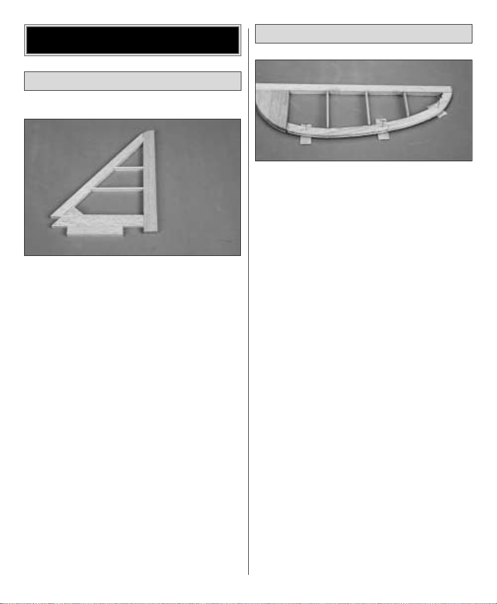
❏❏7. Make two 2-3/4" long servo rail supports
from the die-cut 1/8" x 1/2" x 11" ply strips. Make
two 3-5/8" long servo rails from a 1/4" x 3/8" x
36" basswood stick. Glue the rails and supports
where shown on the plan with the rails spaced as
needed to fit your servo. Mount the ser vo to the rails
with the screws included with your servo.
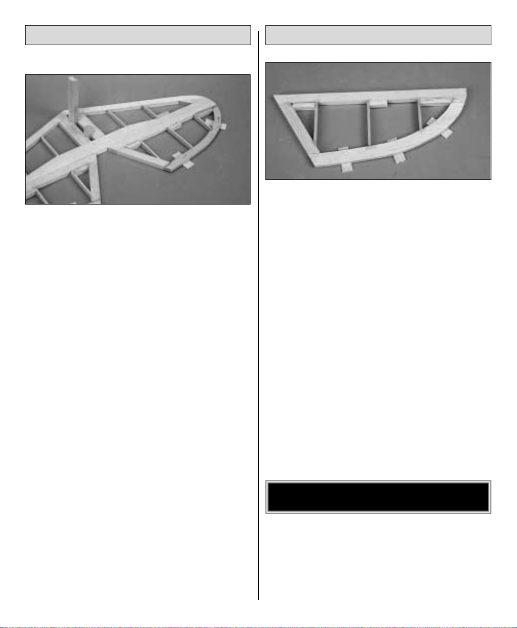
❏❏8. Sheet the area around the servo using
leftover 3/32" balsa so the covering has something
to adhere to. Support the sheeting on the bottom
with strips of 3/32" balsa.
Repeat the above two steps for the second wing
half.
❏ 9. Glue the hardwood landing gear block into
place with 6-minute epoxy.
❏ 10. Cut 1/8" holes through the top wing sheeting
from the bottom side, directly above the servo lead
tubes. From the top of the wing enlarge the holes in
the sheeting to 1/2" diameter centering the holes
above the paper tubes. Cut matching 1/2" holes in
the servo lead tubes.
❏ 11. Use a 3/32" x 3" x 24" balsa sheet to cut, fit
and glue the center sheeting between ribs W1 and the
first W3 on both wing halves. Cut a 3/4" wide strip in
the sheeting above the landing gear block from the
root rib to the end of the landing gear block.
❏ 12. Using the 3/4" strip, as well as leftover
3/32" sheeting, cut and glue filler strips to the
landing gear block so that the strips will be level with
the center sheeting. Cut a grove in these strips for the
3/16" landing gear wire.
❏ 13. From the 3/32" x 3/8" x 30" balsa sticks,
cut, fit and glue the cap strips to the tops of ribs W3
to W6 and the wing tip pieces as you did on the top
of the wing.
❏ 14. Sand the LE to the shape shown on plan.
Rough sand the rest of the wing.
❏ 15. Reinforce the wing center joint using 3"
fiberglass tape and epoxy. Apply the fiberglass to
the top and bottom of the wing.
Page 16

16
❏❏1. Shape the LE of the aileron from a 1/4" x
3/4" x 24" balsa stick using the TE of the wing as a
guide. Shape the aileron LE to the shape of the TE of
the wing without the 3/32" sheeting on it.
❏❏❏❏2. Cut the aileron LE sheeting from a
piece of 3/32" x 1/2" x 24" balsa. Do the same with
the TE from the remainder of the piece of 3/32" x
15/16" x 36". Pin and glue these pieces together over
the plan. Using the leftover pieces of cap strip from the
wing, fit and glue cap strips in place on the aileron.
This is a good time to build the other 3 aileron
frames using the same steps.
❏❏3. Glue the LE piece you made in step one on
the frame work. You will have to unpin the tip end of
the frame work and glue it up against the LE. Glue
the ribs in position on the cap strips.
NOTE: Rib W5A is too small to die-cut to the correct
length. Cut it to length before gluing it in position.
❏❏4. Fit and glue the hinge blocks in place using
leftover 1/4" x 3/4" balsa.
❏❏5. Glue the frame made in step 2, to the
top of the aileron, aligning the TE of the frames to
each other.
❏❏6. Remove the aileron from the plan.
❏❏7. Sand the assembly to the airfoil shown in
the cross section on the plan.
❏8. Build the other aileron by repeating steps 3-7.
NOTE: Before beginning construction of the fuselage
you should determine where you will mount the servos.
There are cutouts for mounting the servos in the
fuselage bottom deck and the rear of the fuselage
sides. If you are installing a gas engine you should
mount the servos in the rear of the fuselage to improve
the balance. The cutouts in the bottom deck can be
used if you are installing a lighter 2-stroke or 4-stroke
engine. Punch out the locations you plan to use and
glue the other cutouts that you will not use into place.
❏1. Place the fuselage plan on your building board
and cover it with wax paper.
BUILD THE FUSELAGE
BUILD THE AILERONS
Page 17

17
❏2. Glue F2D to F2 with medium CA.
❏3. Laminate the three F1 firewalls with 30-minute epoxy .
❏4. Lay the 1/8" die-cut right fuselage side over the
plan. Mark the location of formers IP, F5, F5A, and F7
on the inside of the right fuse side. Place the left
fuselage side above the right side as shown in the
photo and transfer the marks to the top of the left side.
NOTE: There are notches in the fuselage sides to
locate formers F2, F3, F4 and F6.
❏ 5. Locate the two 1/8" x 1/2" x 42" balsa top
longerons. Glue one to the inside of the left fuse side
along the top edge beginning 3/8" back from the
front. Cut the longeron at the notch for the stabilizer
and glue the remainder of the 1/8" x 1/2" stick
along the stab cutout. Glue the other longeron to the
inside of right fuse side beginning 19/32" back
from the front.
❏ 6. Glue the two 1/8" die-cut balsa wing saddle
doublers to the inside of the fuselage sides. Align
them with the wing saddle.
❏ 7. Locate the two 1/8" x 1/2" x 24" balsa
bottom longerons. Glue one to the inside of the left
fuse side along the bottom edge, aligning it at the aft
edge of the wing saddle doubler. Glue the other to
the inside of the right fuse side.
❏ 8. Glue formers F2 and F3 to the inside of the left
fuse side. Use a triangle to insure that the formers
are perpendicular to the fuse side.
❏9. Fit the right fuse side to F2 and F3, sighting across
the top of both sides to align them. When satisfied with
the alignment, glue the right fuse side in place.
Page 18

18
❏10. Slip the 1/8" die-cut ply fuselage bottom deck
through F2 and F3 at a diagonal and rotate into
place, but do not glue.
NOTE: The bottom deck is used to set the right thrust
for the engine. The shorter side of the bottom deck
must be along the right fuselage side. When
satisfied with the fit, glue the bottom deck to F2, F3
and the fuse sides.
❏11. Fit the laminated ply firewall F1 into place. The
firewall should fit tightly against the bottom deck and
the two upper longerons. The front of the left fuselage
side should be even with the front face of the firewall.
The right fuselage side should extend about 1/4" past
the firewall. When satisfied with the fit glue the
firewall into position with 30-minute epoxy.
❏ 12. From the 1/4" x 3/8" x 36" basswood stick,
cut and glue doublers in place behind the firewall
using 30-minute epoxy. After the epoxy has cured you
may want to pin the firewall to the fuselage with small
dowels or toothpicks for additional security. Drill
several small holes through the sides and into the
firewall. Glue toothpicks into these holes with epoxy.
❏ 13. Trim the right fuselage side flush with
the firewall.
IMPORTANT: During the following three steps place
the fuselage over the top view of the plan to aid in
keeping the fuselage straight and square.
❏ 14. Place the triangular tail wheel bracket
between the rear of the fuse sides and pull the fuse
together. You may have to trim and sand the
longerons for a good fit. The notch in the bracket
extends from the bottom of the fuselage. After
checking to make sure the fuse is straight and
square, glue the tail wheel bracket into place. Cut
shims from the 1/4" x 3/8" x 36" balsa stick and
glue them into place as shown on the plan.
❏ 15. Glue formers F5 and F5A together. Using the
notches in the fuse sides and the marks you made
Page 19

19
earlier, glue formers F4, F5, F6 and F7 into place.
Check to insure that the fuselage remains straight
and square.
❏ 16. Note the angle of the instrument panel on
the plan and glue it into place.
❏ 17. Use the 3/32" x 3" x 36" balsa sheet to
sheet across the fuselage bottom from the wing
saddle to the tail. Sheet around the tail wheel
bracket as shown in the photo. Trim the sheeting
flush with the sides of the fuselage.
❏ 18. Using the remainder of the 1/4" x 3/8" x
36" balsa stick, glue the top stringer between F1, F2
and the instrument panel. Sand it flush with the front
of F1 and the rear of the instrument panel.
❏ 19. Glue the 1/4" x 3/8" top stringer between
F3 and F5A, sanding it flush with the front of F3.
❏ 20. Now is a good time to install the control
pushrods of your choice.
❏21. Using the 1/8" x 3" x 24" balsa sheets, sheet
the front top of the fuselage as shown in the photo.
NOTE: You can trim the cockpit opening now or at
step 23.
❏ 22. Sheet the top of the fuselage rear from the
center of the cockpit to F5A.
❏ 23. Trim the sheeting flush with F1 and F5A. Use
the cockpit cutout pattern on the plan to cut the
cockpit opening.
❏ 24. Glue the 1/8" x 1/4" basswood stringers
into position between F5 and F7.
❏25. Glue the 1/4" x 1" x 4" ply wing mount blocks
into place, one on each side of the fuselage, with
Page 20

30-minute epoxy . Glue some doublers to the blocks and
fuselage sides using leftover 1/4" x 3/8" basswood.
❏ 26. Two 1/8" x 1/4" x 36" balsa sticks are
included with the kit. If desired, these can be glued to
the flat fuselage sides as stringers so that the covering
will give the fuselage a more rounded appearance.
❏27. Sand the fuselage and set aside.
Before mounting the stab to the fuselage you should
first carve the stab to fin fairing blocks.
❏ 1. The photo above shows some shim blocks that
have been tack glued into position. The lower shims
are from the leftover 3/8" x 15/16" stick used for
the fin post. The top shim can be cut from the leftover
3/8" x 15/16" stick. These shim blocks will properly
space the fairing blocks.
❏ 2. Locate the two 3/4" x 1" x 8" tail fairing
blocks. Tack glue them into position on the shims and
carve the assembly to shape. When you are satisfied
with your work, remove the fairing blocks and shims
from the fuselage. Clean up the stab mounting area.
Before gluing the stab and fin to the fuselage you
should first mount the wing to the fuselage. This will
allow you to more accurately align the tail section.
❏ 3. Fit the wing to the wing saddle in the fuselage.
Lightly sand the saddle if needed for a good fit.
❏ 4. Center the wing and mark the location for the
dowels on former F2. While carefully holding the
wing in position, drill 1/4" holes through F2 and
into the wing leading edge. Remove the wing and
finish drilling the 1/4" holes into the wing. The holes
should extend into the front ply dihedral brace.
❏ 5. Put the dowels into the wing and fit the wing
back onto the fuselage. Make any adjustments
needed to get the dowels to fit properly in the holes
in former F2. When satisfied with the fit, glue the
dowels into the wing with 6-minute epoxy. Use
caution not to get any epoxy on the fuselage.
FINAL ASSEMBLY
20
Page 21

❏ 6. Align the wing squarely on the fuselage. This
is easily done using a piece of string as a guide. Put
a pin in the tail of the fuselage at the centerline. Tie
a loop in the end of the string and place it over the
pin. Move the other end of the string to one wing tip
and put some masking tape around the string. Draw
an arrow on the tape where it reaches the wing tip.
Now swing the string over to the other wing tip. If
the tip aligns with the arrow the wing is properly
aligned. If not, adjust the wing’s position and try
again. Continue to adjust the wing until both wing
tips are aligned with the arrow on the tape.
❏ 7. Secure the wing exactly in this position. Drill
the two 13/64" tap holes for the 1/4-20 wing bolts.
Drill the holes through the wing and into the ply
wing bolt plates so that the holes will be centered
fore/aft in the plates.
❏ 8. Remove the wing from the fuselage. Tap the
holes in the ply plates for the bolts. Apply thin CA to
harden the threads and tap the holes again.
❏ 9. Locate the two 1/16" die-cut ply wing bolt
plates. Glue these into position over the wing bolt
holes with 6-minute epoxy. Enlarge the wing bolt
holes in the wing with a 1/4" drill, drilling through
the 1/16" ply plates.
❏ 10. Glue the 3/4" x 1" x 6" basswood landing
gear block into place with 30-minute epoxy. Make
sure it is glued to former F2.
❏ 11. Use a 1/8" x 2-3/4" x 6" ply sheet to sheet
the area between the landing gear block and firewall.
NOTE: If you will be mounting any servos in the
nose area you will need to fabricate a hatch instead
of sheeting this area.
❏12. Drill a 1/4" hole into the landing gear block to
clear the wing dowels. Do not drill all the way through
the block. (Refer to the side view of the fuse plan)
❏ 13. Mount the wing to the fuselage and bolt it
into place. Place some wax paper between the
leading edge and former F2.
21
Page 22

❏ 14. Use the remainder of the 3/8" x 15/16"
stick to make a fairing between the bottom of the
wing and former F2.
❏ 15. You can now glue the stab and fin to the
fuselage. To increase the gluing area, glue some
leftover 3/8" stick to the inside of the fuselage sides
at the stab saddle.
❏ 16. Place the stab on the fuselage and align with
the wing and center line of the fuselage. Use the
same string technique that you used for aligning the
wing. Be sure that the stab aligns with the wing
horizontally as well. When satisfied with the fit and
alignment, glue the stab to the fuselage with
30-minute epoxy.
❏ 17. Glue the fin to the stab with 30-minute epoxy
using a 90 degree triangle for alignment. Be sure that
the fin is aligned with the centerline of the fuselage.
❏18. When the fin is secure, glue the fairing blocks
into place.
❏19. Fill in the area behind and in front of the stab
with leftover balsa. This area extends from the fuse
to the fin and from the fuse to the stab.
❏ 20. Locate the tailwheel assembly. Attach the
assembly to the fuselage using CA. Use thin glass
cloth to glass the tube to the 1/8" die-cut ply
tailwheel bracket. Glue the 1/16" ply sides into
place. One goes on each side, sandwiching the core
and tube between them. Sand to final shape.
NOTE: If you plan to fly on grass you may want to
reinforce the mounting of the tailwheel tube by
wrapping it with a brass or aluminum sheet.
❏ 21. Bring the rudder up to the fuse and mark the
protruding part of the tail wheel wire onto the rudder.
Drill a 3/32" hole into the rudder at this mark.
❏ 22. While the wing is still on, build the landing
gear. The front wire is 1/4", the rear is 3/16".
Mount the front wire into the front block using the
nylon straps and screw it into place.
22
Page 23

❏ 23. Mount the rear wire into the wing block. You
will need to notch the landing gear block so the wire
can rotate forward.
❏ 24. Bring the ends of the wire together by the
axle. If they don’t match as shown in the above
photo, bend the rear wire to fit. Clean off any
manufacturing oil with alcohol. Sand the wires so
they are clean and shiny. Wrap the joint area with
wire. Coat the area with an acid flux to prepare the
joint. Solder the joint with silver solder and a
propane torch.
NOTE: To improve ground handling, it is
recommended that you bend the 1/4" main wire to
impart 2Þ of toe-in to the landing gear wheel.
❏25. Remove the landing gear from the airplane to
finish. Add the basswood airfoil fairing to the legs
using CA to hold them in place. Apply glass cloth to
glass the fairings to the wire and to each other as
shown. Use Bondo®filler to blend the assembly. The
gear should be ready to prime and paint but hold
off until the cowl is ready.
NOTE: To remove the wing when the Fly Baby is
done, unlatch the rear wire and rotate the gear
forward, then remove the wing. When transporting,
the gear will keep the fuselage upright.
❏ 26. Mount your engine using the mounting
system you have chosen. The photo shows our
installation of the US Engines 25cc engine on our
vibration dampening mount system.
❏27. Glue the 3/4" x 3/4" x 3/4" basswood cowl
mount blocks into place. Sand them to the contour of
the fuselage.
❏ 28. Draw a line on the fuselage where the cowl
should end. Draw lines from the cowl mount blocks
back to this line. Measure from the cowl rear line to
the center of the mount blocks and write down this
dimension for each block for later reference.
❏ 29. Fit the cowl. The plastic cowl comes in halves
and needs to be glued together. The kit includes a
23
Page 24

strip of plastic that is used to reinforce the joint on
the inside. Thin CA works well for this. Fill in the
joints with Bondo®or a similar filler. When you have
glued the cowl together, cut a small hole where the
prop shaft needs to exit. Slip the cowl onto the
fuselage and see how close you are. Enlarge the
hole as needed to clear the engine thrust washer. As
you continue to fit the cowl to the fuselage and
engine you may need to remove and reinstall the
engine several times. We have found that using a
piece of cardboard taped to the side of the fuselage
is the easiest way to locate the cutout for the engine.
Tape the cardboard to the fuselage and cut an
opening in it to fit your engine, remove the engine,
install the cowl and transfer the cutout to the cowl. If
you go slowly and remove a little material each time
from the cowl, you will be rewarded with a good
looking cowl.
❏30. To drill the mounting holes in the cowl, extend
the reference lines you drew earlier forward. Use
the dimensions you wrote down earlier to locate the
position of each hole. Drill the holes with a 1/16" bit
and mount the cowl with #6 x 1/2" sheet metal
screws. Enlarge the holes in the cowl only to 3/32"
❏ 31. Now is a good time to install your fuel
system. As this will vary widely with the type of
engine used we will offer only a few guidelines. If
you are installing a Gasoline fuel system and are not
familiar with them be sure to use a fuel tank, fuel
lines and other components designed for gasoline.
Install the engine kill switch away from the prop and
hot exhaust. And be sure to carry a fire extinguisher
whenever you fly. As the fuel system is completely
enclosed you will need a refueling valve. You will
need to build a tank floor to mount the tank. The kit
includes a 1/4" x 3/8" x 36" basswood stick to
make rails for the tank floor and for servo rails. The
floor can be made from leftover 1/8" ply material.
❏ 32. With the engine and cowl still mounted, let’s
do a quick C.G. estimate. Tape the elevators and
rudder into place. Mount the wing. If you are using
a gas engine you will be nose heavy. Put three
servos on the stab and your radio on the trailing
edge of the wing. This should get you close to
balance. If not you may want to consider putting the
radio in the tail. With other engines place the servos
and radio forward until the balance is close.
❏ 33. Mounting holes for the servos have been
provided in the aft fuselage sides, in the fuselage
bottom deck at the aft edge of the wing and in the
fuselage bottom deck aft of the firewall. The photo
shows servos in the tail. You can also install servo rails
cut from 1/4" x 3/8" x 36" basswood, which is
provided in the kit. If using a small 2 or 4-stroke engine,
the servos should be installed just behind the firewall.
❏ 1. Cover the model. The original Fly Baby was
covered in fabric and then painted. Coverite 21
st
Century pre-painted Fabric was designed for models
of this type and looks great on this airplane. To
duplicate the color scheme on the box you will need
one 15 foot roll of White (COVQ0401), and one six
foot roll of Blue (COVQ0312), Dark Red
(COVQ0303), Orange (COVQ0307) and Cub
Yellow (COVQ0304). There are also many other
color schemes available as well.
❏ 2. To install your windshield, cut it from the
butyrate strip using the pattern on the plan. Fit it to
the fuselage. Cut the covering where it will be glued
to the fuselage so that the windshield can be
adhered to the wood.
❏ 3. Don’t forget to fuelproof the engine and
tank area.
❏4. Paint the cowl and landing gear.
FINISHING
24
Page 25

❏5. Mount the wheels.
❏6. Hinge the rudder, elevators and ailerons with the
heavy-duty hinges you have chosen.
❏ 7. Mount the control horns onto the rudder,
elevator, and ailerons.
❏ 8. Install the radio system. Our radio installation
consisted of the following:
A.We used one hi-torque servo for each aileron.
B. We used one hi-torque servo for each elevator,
with a separate pushrod for each.
C.W e used one hi-tor que servo for the rudder.
D.We used a standard servo for the throttle.
E.We used a 1200 Mah battery pack to allow for
the additional servo drain.
❏ 9. Install hi-torque aileron ser vos in the wing and
connect the linkages. We recommend the following
hardware for this purpose:
4-40 x 12" rod, threaded on one end (2)
4-40 threaded metal clevis (2)
4-40 lock nut (2)
Metal solder clevis (2)
❏ 10. Fit and install the servos for the elevators and
rudder. Connect the linkages to the servos. If the
servos are mounted in the rear of the fuselage we
recommend the following hardware for this purpose:
4-40 x 12" rod, threaded on one end (3)
4-40 threaded metal clevis (3)
4-40 lock nut (3)
Metal solder clevis (3)
If the servos are mounted just aft of the firewall, you
will need a pushrod system 42" long. If the servos
are mounted at the TE of the wing, you will need a
pushrod system 28" long. In either case, Great
Planes solid wire pushrods or Accu-Glide
™
Nylon
Pushrods would work well.
❏ 11. Install the throttle servo and connect the
linkage to the engine.
❏ 12. Finish the cockpit. The cockpit area was
designed to be structure free so you can add as
much detail as desired. An optional cockpit kit is
available for this model and can be installed at any
time. Details in the cockpit area will really dress up
the appearance of your model.
Measure the throws at the widest part of the trailing
edge of the rudder, ailerons and elevators. After a
few flights you may change the throws to suit your
flying style.
We recommend the following control surface
throws:
HI LOW
Elevator 1-1/16” Up 7/8” Up
1-1/16” Down 7/8” Down
Rudder 1-3/4” Left 1-1/2” Left
1-3/4” Right 1-1/2” Right
Ailerons 1-1/8” Up 13/16” Up
15/16” Down 11/16” Down
Throttle: Set the throttle so that at “high stick” the
carburetor barrel is fully open and at “low stick”
with full to half throttle trim, the carburetor barrel
is nearly closed. At this position the engine should
run reliably at a low RPM (idle). To shut the
engine off, decrease the throttle trim tab.
SET THE CONTROL THROWS
25
Page 26

This section is important and must not be omitted. A
model that is not properly balanced will be unstable
and possibly unflyable.
❏ 1. Check the balance point with all components
installed in the model and the fuel tank empty.
Attach the wing to the fuselage, then accurately
mark the balance point on the top of both wing
halves next to the fuselage. The balance point is
shown on the plan and is 3-5/8" (92 mm) aft of the
leading edge.
❏ 2. Lift the model with your fingers at the balance
point or use the Great Planes CG Machine
™
(GPMR2400). If the tail drops, shift the receiver
and/or battery for ward (if possible) to balance the
model. If the nose drops, shift the receiver and/or
battery pack aft. If possible arrange the batter y pack
and receiver to achieve balance but make sure they
remain secure in the fuselage so they cannot shift
during flight or a rough landing. If you must add
additional weight to the nose or tail of the Fly Baby
to achieve balance, use Great Planes adhesive lead
weight (GPMQ4485). An alternative to stick-on nose
weight (if your model is tail heavy) is a Great Planes
brass spinner nut (GPMQ4640). It has 1/4-28
threads so it will fit most engines.
Balance Your Propellers
Balancing the propeller seems like one of those
things that you can skip, but many problems are the
result of vibration caused by an unbalanced
propeller. Nuts and bolts can vibrate loose and
vibration can damage delicate radio components
inside your receiver and servos. Vibration can even
damage the delicate glow plug element which could
result in an engine that is difficult or impossible to
start. Purchase a Top Flite Precision Magnetic
Balancer™(TOPQ5700) or a Great Planes Fingertip
Prop Balancer (GPMQ5000) to accurately balance
your propellers.
Charge Your Batteries
Follow the battery charging instructions in the
instruction manual that came with your radio control
system. You should always charge your batteries the
night before you fly.
Ground Check Your Model
Inspect all nuts, screws and wheel collars. Make
sure you install the screw that holds the servo ar m
onto the servos and the servo cords are securely
connected to the receiver. If you are not thoroughly
familiar with R/C models, ask an experienced
modeler to inspect your radio installation and make
sure the control surfaces respond correctly. The
engine must be “broken-in” according to the engine
manufacturer’s recommendations for break-in. Refer
to the Engine Safety Precautions on the next page
before you start your engine. After you run the
engine on the model make sure all screws remain
tight, the hinges are secure and the prop is on tight.
Range Check Your Radio
Check the operational range of the radio before the
first flight. Before you turn your radio on, the first
AT THE FLYING SITE
AT HOME
PREFLIGHTBALANCE THE MODEL
26
Page 27

thing you always must do is make sure no one else
is on your frequency (channel). Most model flying
fields utilize frequency control so familiarize yourself
with their system. Collapse your transmitter antenna
and turn on the transmitter first, then the receiver
(preferably the receiver should never be on by itself).
You should be able to walk at least 100 feet away
from the model and still have control. Have an
assistant stand by your model and tell you what the
control surfaces are doing while you operate them
from the transmitter. Repeat this test with an assistant
holding the model and the engine running at
various speeds. If the control surfaces do not always
respond correctly, don’t fly! Find and correct the
problem first. Look for loose servo connections or
corrosion, loose fasteners that may cause vibration,
a defective on/off switch, low battery voltage or a
defective cell, a damaged receiver antenna or a
receiver crystal that may have been damaged from
a previous crash.
NOTE: Failure to follow these safety precautions may
cause severe injury to yourself and others.
Store model fuel in a safe place away from high
heat, sparks or flames. Do not smoke near the
engine or fuel as it is very flammable. Engine
exhaust gives off a great deal of deadly carbon
monoxide so do not run the engine in a closed
room or garage.
Get help from an experienced modeler when you
learn to operate engines.
Use safety glasses when you operate model engines.
Do not run the engine near loose gravel or sand; the
propeller may throw loose material in your face
or eyes.
When you start and run the engine keep your face
and body as well as all spectators away from the
plane of rotation of the propeller.
Keep loose clothing, shirt sleeves, ties, scarfs, long
hair or loose objects away from the prop. Be
conscious of pencils, screwdrivers or other objects
that may fall out of your shirt or jacket pockets.
Use a “chicken stick” or electric starter and follow
the instructions to start your engine.
Ask an assistant to hold the model from the rear
while you start the engine and operate the controls.
Make all engine adjustments from behind the
rotating propeller.
The engine gets hot! Do not touch the engine during
or immediately after you operate it. Make sure fuel
lines are in good condition so fuel will not leak onto
a hot engine and cause a fire.
To stop the engine, close the carburetor barrel (rotor)
or pinch the fuel line to discontinue the fuel flow. Do
not use your hands, fingers or any body part to stop
the engine. Never throw anything into the prop of a
running engine.
The best place to fly your R/C model is at an AMA
(Academy of Model Aeronautics) chartered club
field. Ask your hobby dealer or the AMA if there is
a club in your area and join it (the address and
telephone number for the AMA is listed on page 3
of this instruction book). Club fields exist to make
your R/C flying safe and enjoyable. We recommend
that you join the AMA and a local club so you may
have a safe place to fly and insurance in case of a
flying accident.
If a club flying site is not available, find a large, grassy
area at least 6 miles away from houses, buildings,
streets and other R/C activity like boats and cars.
Avoid flying R/C models near traffic or areas such as
FIND A SAFE PLACE TO FLY
FLIGHT
ENGINE SAFETY PRECAUTIONS
27
Page 28

parks, school yards, office building lawns, etc. that
may attract unrestrained observers (wild kids). If you
are a beginner, you are busy enough concentrating on
your model without having to answer lots of questions
and performing crowd control.
We highly recommend that you get an experienced
modeler to assist you with your flight training. An
experienced modeler can take your Fly Baby up for
the first time and make sure it performs correctly, then
give you valuable flight instruction. He can hand you
the transmitter when the Fly Baby has climbed to a
safe altitude or connect your transmitter to his if both
of your systems have a trainer cord or “buddy box”
capability. Assistance from an experienced modeler
will make your modeling “career” progress faster
(and cheaper). We do, however realize that some
modelers are determined to learn on their own or are
not in a location where an instructor or flying club is
available. Therefore, we have provided the following
information to give you an idea of what to expect on
your first flight with your Fly Baby. Both flyers who
plan to set out on their own and fliers who will have
the help of an instructor should carefully read the
following information.
First flight attempts should be reserved for calm days
when the wind speed is less than five mph. Always
takeoff (and land) into the wind. Check the
operation of all controls just before takeoff. This will
eliminate the possibility of overlooking reversed or
disconnected controls (it happens).
As you apply power on takeoff you will need to
apply a slight amount of right rudder to compensate
for engine torque. Be ready for this and correct its
heading immediately to avoid an “exciting” take off
roll. The tail will rise almost immediately, indicating
that the tail surfaces have gained effectiveness.
Allow the model to continue to accelerate until it has
reached flying speed. Use as much of the available
runway as you can. Then, gently apply some up
elevator. Your Fly Baby should slowly lift from the
runway. Continue straight ahead until you have
accelerated to a safe flying speed.
The design of the Fly Baby aircraft originated in
model aviation of the early 1930’s, an era when
aviation was in it’s infancy. The Fly Baby model was
a high wing airplane that looked very much like the
later full scale Fly Baby, except for the placement of
the wing. The full scale Fly Baby was designed for
an EAA (Experimental Aircraft Association) contest
that had as it’s goal the development of easy to
build, inexpensive, towable homebuilt aircraft. The
Fly Baby was an all wood aircraft that could be
typically built in 750 to 1000 hours.
The Fly Baby is a “sport” airplane. It’s not a Piper
Cub type aircraft, and it’s not an aerobatic Citabria
either. It is a fun, easy to fly, forgiving aircraft that is
ideal for a Sunday flier to have a great day of open
cockpit flying. The Fly Baby will perform scale
aerobatics such as loops, rolls, spins and stall turns.
We encourage you to fly your Fly Baby in a scale
manner – slow and smoothly, like the real thing.
Avoid unrealistic “hot dog” maneuvers that could
over-stress the structure. It will be easier on your
model and lot more enjoyable for you!
Before attempting your first landing you should first
try some slow flight and stalls to become familiar
with the Fly Baby’s slow speed characteristics. You
will probably find the model slows down quicker
and requires more power on landing than you are
used to. Remember that aircraft of the Fly Baby’s era
had high drag and limited low speed control
effectiveness, especially the ailerons. The rudder is
very effective however.
On landings, you will need to continue to carry power
and speed until you initiate the flare, then reduce
power and allow the model to gently settle to the
ground. If you must go around, add power and
accelerate straight ahead. Do not attempt to climb or
turn until you have accelerated to a safe flying speed.
We hope you enjoy the realistic looks and
performance of your Fly Baby.
LANDING
FLYING
TAKEOFF
 Loading...