

Page 1
• Simple Entry Level Construction
• Stable Flight Characteristics
• Excellent R/C Trainer
READ THROUGH THIS INSTRUCTION MANUAL FIRST. IT CONTAINS
IMPORTANT INSTRUCTIONS AND WARNINGS CONCERNING THE ASSEMBLY
AND USE OF THIS MODEL.
Instruction Manual
Dynaflite guarantees this kit to be free from defects in both material and workmanship at the
date of purchase. This warranty does not cover any component parts damaged by use or
modification. In no case shall Dynaflite's liability exceed the original cost of the purchased kit.
Further, Dynaflite reserves the right to change or modify this warranty without notice. In that
Dynaflite has no control over the final assembly or material used for final assembly, no liability
shall be assumed nor accepted for any damage resulting from the use by the user of the final
user-assembled product. By the act of using the user-assembled product, the user accepts all
resulting liability. If the buyer is not prepared to accept the liability associated with the use of
this product, return this kit immediately in new and unused condition to the place of purchase.
DDRMP03 Printed in USA
WARRANTY
Entire Contents © Copyright 2000
Page 2
Introduction
Precautions
Preparations...................................:...................3
Required Items..............................................................3
Suggested Building Supplies
Optional Building Supplies
Building
Adhesives
Glossary of Terms Used in
This
Manual & Plans
Die-Cut
Build
the
Build the Formers
Build
the
Bevel the
Cutting
Build
the
Fuse
Side Construction
Fuse
Structure
Preparing the Canopy
Build
the
Joining
Align
the
Install
the
Balance
Finishing............................................................19
Final
Assembly
Radio
Installation..............................................20
Pushrod
Final
Hookups & Checks
Radio Settings
Balance
Checking
Preflight............................................................
Charge
Find a Safe
Range Check
AMA
Safety
Flying ................................................................25
Trim
Flights
Your First Hi-start Launch
First
Flights
Thermal
Facts
About
Thermal Soaring................................................27
Pointers
Slope
Soaring....................................................29
Flying
Slope Landings
Ballasting..........................................................30
Flight
Log
........................................................2
........................................................2
......................................3
..........................................4
Notes
....................................................4
......................................................................5
..........................................5
Pattern
the
Wing
the
the
Installation..........................................21
the
for
the
Flying
for
..........................................................................29
..................................................7
Stabilizer & Elevator
Fin
Fin & Rudder
Hinge
Fuselage
Wing
Stab
Forward Wing
Model
Model
Batteries
Place
Code (excerpt)
......................................................25
......................................................26
Thermals........................................27
Contest
............................................Back
........................................................8
and Rudder
Assembly............................................
..................................................14
to
..................................................19
............................................................22
Warps
the
..................................................26
..........................................................29
................................................9
Slots
..............................................10
............................................10
..............................................10
................................................13
Panels....................................17
the
Wing
Laterally
............................................22
..........................................23
........................................24
to
Fly
Radio
....................................24
....................................24
Flying
..........................8
....................................9
..............................18
Fillet..........................18
............................19
..................................22
..............................24
................................25
..............................28
Cover
24
Congratulations on your choice of this kit for
your project. If you are new to Radio Control
Modeling, we would like to take a minute to
give you some information on the Daydream.
The Daydream was designed to use a modern
airfoil specifically designed for thermal gliders.
The construction of the Daydream uses the
minimum amount of materials to keep the
overall weight down. The combination of these
provides you with a model that will be able to
catch and ride out the slightest thermal.
At Dynaflite we take pride in offering kits that
are simple and straightforward to build and
11
provide value for your modeling dollar.
To make your R/C modeling experience totally
enjoyable, we recommend that you get
assistance with your first flights from an
experienced, knowledgeable modeler. You'll
learn faster and avoid risk to your model before
you're truly ready to solo. Your local hobby
shop has information about flying clubs in your
area whose membership includes qualified
instructors.
You can also contact the national Academy of
Model Aeronautics (AMA), which has more than
2,500 chartered clubs across the country. We
recommend you join the AMA, which will
provide you with insurance coverage at AMA
club sites and events. AMA Membership is
required at chartered club fields where qualified
2
Page 3
flight instructors are available. Contact the AMA
at the address or toll-free phone number below:
Academy of Model
Aeronautics
5151 East Memorial Drive
Muncie, IN 47302
(800) 435-9262
Fax (765) 741-0057
Internet address:
http://www.modelaircraft.org
1.You must assemble the sailplane according to
the instructions. Do not alter or modify the
model, as doing so may result in an unsafe or
unflyable model. In a few cases the instructions
may differ slightly from the photos or plan. In
those instances the text should be taken as
correct.
2.You must take time to build straight, true and strong.
3. You must install all R/C and other components
so that the model operates properly on the
ground and in the air.
4. You must test the operation of the model
before the first and each successive flight to
insure that all equipment operates correctly.
You must also make certain that the model has
remained structurally sound, especially after a
rough landing.
parts are missing, broken or defective, or
if you have any questions about building
or flying this model, please call us at
(217) 398-8970 and we'll be glad to help.
If you are calling for replacement parts,
please look up the part numbers and have
them ready when calling.
You may also e-mail us at:
productsupport@dynaflite. corn
REQUIRED ITEMS
These are the items not included with your
kit-you will need to purchase them separately.
Items in parentheses such as (GPMQ4243) are
suggested part numbers recognized by distributors
and hobby shops and are listed for your
ordering convenience. GPM is the Great Planes®
brand, TOP
Hobbico® brand and DYN is the Dynaflite brand.
2 - 4 Channel Radio with two standard servos
Top Flite MonoKote® (approximately 2 rolls)
1/4" Latex Foam Rubber Padding (HCAQ1050)
Switch and Charge Jack (GPMM1000)
2 Meter Up-Start (DYNP8305) or Standard
Hi-Start(DYNP8301)
is
the
Top
Flite®
brand,
HCA
is
the
Note: We, as the kit manufacturer, provide you
with a quality kit and great instructions, but
ultimately the quality and flyability of your
finished model depends on how you assembled it;
therefore, we cannot in any way guarantee the
performance of your completed model and no
representations are expressed or implied as to the
performance or safety of your completed model.
Please inventory and inspect all parts
carefully before starting to build. If any
SUGGESTED BUILDING
SUPPLIES
We recommend Great Planes Pro CA and
Epoxy glue.
2 oz. Pro CA (thin, GPMR6003)
2 oz. Pro CA+ (medium, GPMR6009)
3
Page 4
6-Minute Pro Epoxy (GPMR6045)
30-Minute Pro Epoxy (GPMR6047)
4 oz. Pro Wood Glue (GPMR6161)
Hand or Electric Drill
Sealing Iron (TOPR2100)
Hobby Saw
Hobby Knife (HCAR0105)
#11 Blades
Pliers (common and needle nose)
Screwdrivers (phillips)
T-pins(HCAQ5150)
60" RetractableTape Measure (HCAR0478)
Straightedge with scale
MaskingTape (TOPR8018)
Sandpaper (coarse, medium, fine grit)
Easy-Touch'" Bar Sander (or similar)
Plan Protector (GPMR6167)
Lightweight Balsa Filler such as Hobbico
HobbyLite'" (HCAR3400)
IsopropyI Rubbing Alcohol (70%)
Ballpoint Pen
90° Building Square
Heavy Sewing Thread (any color)
#64 Rubber Bands
Drill bits: 1/16", 5/64", 3/32", 3/16", 1/4"
OPTIONAL BUILDINGOPTIONAL BUILDING
SUPPLIES
Single-Edge Razor Blades (HCAR0312)
Heat Gun (TOPR2000)
Razor Plane (Master Airscrew®)
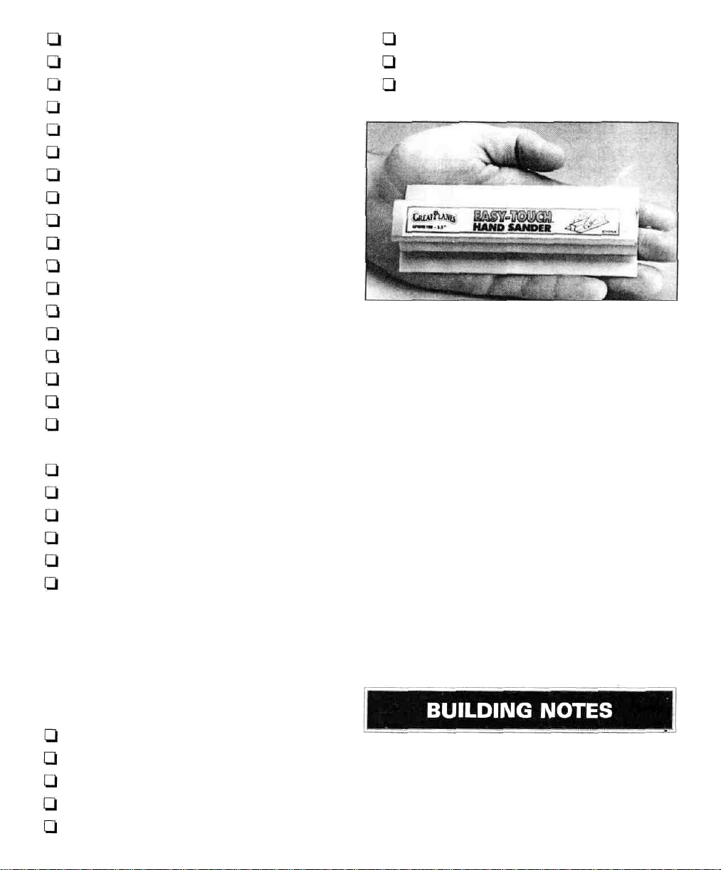
Great Planes Easy-Touch Bar Sanders are
made from lightweight extruded aluminum and
can be found at most hobby shops. They are
available in five sizes - 5-1/2" (GPMR6169) for
those tight, hard to reach spots; 11"
(GPMR6170) for most general purpose sanding;
and 22" (GPMR6172), 33" (GPMR6174) and 44"
(GPMR6176) for long surfaces such as wing
leading edges. Easy-Touch Adhesive-Backed
Sandpaper comes in 2" x 12' rolls of 80-grit
(GPMR6180), 150-grit (GPMR6183) and 220-grit
(GPMR6185) and an assortment of 5-1/2" long
strips (GPMR6189) for the short bar sander.The
adhesive-backed sandpaper is easy to apply
and remove from your sanding bar when it's
time for replacement.
This setup is all that is required for almost any
sanding task. Custom sanding blocks can be
made from balsa or hardwood blocks and
dowels for sanding difficult to reach spots.
CAApplicatorTips (HCAR3780)
Epoxy Brushes (GPMR8060)
Epoxy Mixing Sticks (GPMR8055)
CA Debonder (GPMR6039)
Hot Sock" (TOPR2175)
•When you see the term "test fit" in the
instructions, it means you should first
position the part on the assembly without
using any glue and then slightly modify or
sand the part as necessary for the best fit.
4
Page 5

•Whenever the instructions tell you to glue
pieces together, thin CA should be used.
When a specific type of glue is required,
the instructions will state the type of glue
that is highly recommended. When 30-minute
epoxy is specified, it is highly recommended
that you use only 30-minute (or slower)
epoxy because you will need either the
working time and/or the additional strength.
Airfoil: A curved structure designed to create
lift by the reaction to air moving over its surface.
• Do not throw away any leftover material
until after you have completed your model.
Some small pieces of leftover balsa or
plywood are used during construction.
ADHESIVES
This kit is built with three types of glue.
Cyanoacrylate - CA glues cure almost instantly
and are moderately strong. There are three
common types used: thin, medium and thick.
Thin CA cures the fastest but will not span gaps
between parts. Medium and thick CA are used
where parts do not fit perfectly. CA glue does
not bond well to most plywoods and
hardwoods. CA glues are also brittle. When
using CA glues we recommend keeping a bottle
of CA debonder on your building table.
Aliphatic Resin - Resin glues require that
parts be pinned or clamped together while the
glue dries - typically 15 to 30 minutes. Resin
glues are very strong and work well with balsa
and plywoods.
Epoxy - Six minute epoxy cures the fastest; it
sets within six minutes but is not fully cured for
one hour or more. Thirty minute epoxy is the
strongest as it allows the epoxy to soak into the
wood thoroughly. While it sets within 30 minutes,
it is not fully cured for two or more hours.
C.G. (Center of Gravity): This is the point at
which the model balances forward and aft and
side-to-side.
Clevis: A small clip which is threaded onto the
wire end of a pushrod and connects the
pushrod to the control horn of a control surface.
The threads allow fine adjustment of the
pushrods' length.
Control Horn: The arm which is attached to a
control surface at the hingeline and is
connected to a pushrod.
Die-cut Parts: Precut parts stamped out of a
sheet of wood. The parts require a minimum of
preparation.
Dihedral: The V-shaped bend in the wing.
Typically more dihedral causes more aerodynamic
stability in an airplane, and causes the rudder to
control both the roll and yaw axis.
Doubler: Part of the structure that is laminated
to another part to increase its strength.
Elevator: The hinged control surface located at
the trailing edge of the horizontal stabilizer,
which provides control of the model about the
pitch axis and causes the model to climb or
dive. The correct direction of control is to pull
the transmitter elevator control stick back,
towards the bottom of the transmitter, to move
the elevator upward, which causes the airplane
to climb and vice versa to dive.
Foam Rubber: A soft foam material used to
wrap the receiver and receiver battery for
protection.
5
Page 6

Gusset: A brace used to reinforce the joint
between two parts.
High-start: A device used to launch a model
glider like a slingshot. This device consists of a
stake, an elastic tube, monofilament line (or
string), a parachute or streamer and a ring for
attaching the high-start to the glider.
Laminate: The process of gluing a multiple
number of sheets face-to-face to increase
strength.
Horizontal Stabilizer: The non-moving horizontal
tail surface at the back of the fuselage which
provides aerodynamic pitch stability.
Sailplanes are launched by several methods: a
giant sling shot called a high-start or a winch
which pulls the sailplane up like a kite.
Servo: The electronic/mechanical device which
moves the control surfaces of the sailplane
according to the commands from the receiver.
The radio device which does the physical work
inside the sailplane.
Servo Arm:The removable arm or wheel which
bolts to the output shaft of a servo and connects
to the pushrod.
Tow Hook: A device used to connect the tow
line to the sailplane during launch.
Pitch Axis:The sailplane axis controlled by the
elevator. Pitch is illustrated by holding the
sailplane at each wingtip. Raising or lowering
the nose is the pitch movement. This is how the
climb or dive is controlled.
Pushrod: A rigid piece of steel, plastic or wood
used to transfer movement from a servo to a
control surface.
Receiver (RX):The radio unit in the sailplane
which receives the transmitter signal and relays
the control to the servos. This is somewhat
similarto the radio you may have in yourfamily
automobile, except the radio in the glider
perceives commands from the transmitter and
the radio in your car perceives music from the
radio station.
Rudder: Hinged control surface located at the
trailing edge of the vertical stabilizer, which
provides control of the sailplane about the yaw
axis and causes the sailplane to yaw left or
right. Left rudder movement causes the sailplane
to yaw left and right rudder movement causes it
to yaw right.
Transmitter: The hand-held radio controller.
This is the unit that sends out the commands
that you input.
Vertical Stabilizer: The non-moving surface
that is perpendicular to the horizontal stabilizer,
often referred to as the fin, providing lateral
stability. The rudder attaches to this surface.
Wing:The main lifting surface of an airplane.
Yaw Axis: The glider axis controlled by the
rudder. Yaw is illustrated by hanging the glider
level by a wire located at the center of gravity.
Left or right movement of the nose is the yaw
movement. Many gliders are not equipped with
ailerons and the roll and yaw axis are controlled
by the rudder. This is due to the larger amount
of dihedral in the wing and is why most
sailplanes have a large amount of dihedral.
Sailplane: An airplane which flies without an
engine. Sailplanes are designed to ride on
warm, rising air currents, called thermals.
6
Page 7
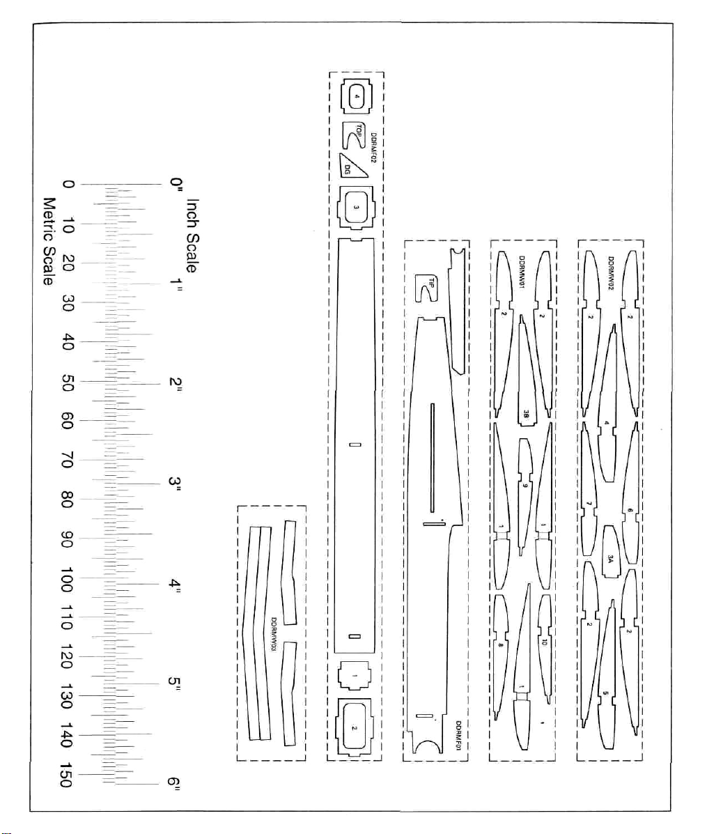
Die-Cut Pattern
7
Page 8
BUILD THE FORMERS
Q 1. Unroll the plan. Re-roll the plan inside out
to make it lie flat. Wax paper or Great Planes
Plan Protector" placed over the plan will
prevent glue from sticking to the plan.
Start by cutting and placing the longest piece
first, working until you are placing the shortest
(end) pieces. Glue each piece together using
medium CA as you proceed.
BUILDING HINT:
If you are unfamiliar with "Built-up"
construction, we have found that the
following method is very easy and accurate.
A. Position an uncut stick directly over the
plan and pin it in place.
Q 2. Place the 3/16" x 1" x 14" balsa stick over
the portion of the plan marked leading edge
joiner, and line up the back edge of the stick
with the straight line. Draw two angled lines
where you will cut this stick. There are two
dashed lines on the plan to help in drawing the
lines in the correct location. Remove the stick
from the plan and cut the stick along the lines
using a hobby knife or razor saw. Straighten
and square the cut edges with a sanding block.
Trim the ends slightly to match the length
shown on the plan.
Q 3. Pin the stab forward center into position on
the plan. Test fit the 3/16" x 2" x 3" balsa stab
center into place. There should be no gaps
between the center and forward pieces. After
fitting, pin and glue the center to the forward
using medium CA.
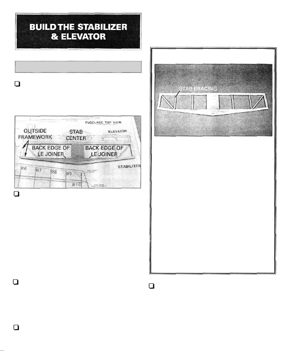
Q 4. Use two 3/16" x 3/8" x 36" balsa sticks to
build the outside framework of the stabilizer.
B. Mark each side of the stick where it ends
or butts with another part.
C. Remove the stick from the building
surface and flip it over. Draw a line
between the marks you made previously
using a straightedge.
D. Using a razor saw, cut as close to the line
as possible. Then, with your sanding block,
true-up the ends to the line. Flip the part
over and pin back in place over the plan.
0 5. Cut and install the stab bracing using a
3/16" x 3/16" x 36" balsa stick. Note: It is best to
start with the straight pieces, then go to the
angled pieces. The alignment of each piece to
the plan is not critical, just as long as it is close
and fits snugly into position. Use the remaining
wood from the stab forward center for the
gussets in the corners.
8
Page 9
Q 6. Remove the stabilizer from your building
surface. Examine and add thick CA glue to any
open joints, then use your sanding block with
medium (150-grit) sandpaper to sand both
sides of the stabilizer framework smooth.
Q 3. Remove the rudder from your building
surface. Examine and add thick CA glue to any
open joints, then use your sanding block or bar
sander with medium (150-grit) sandpaper to
sand both sides of the rudder smooth.
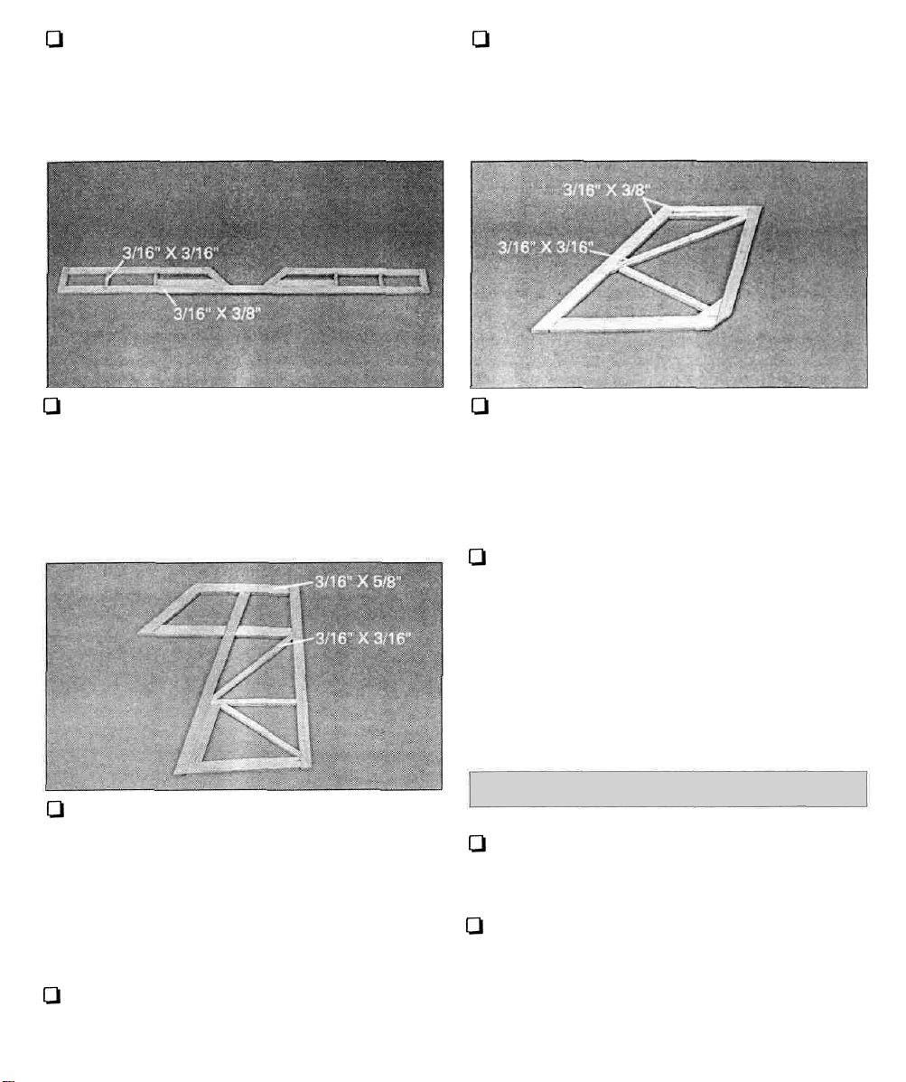
Q 7 Build the elevator from the 3/16" x 3/16" x 36"
balsa sticks and the 3/16" x 3/8" x 36" balsa sticks.
BUILD THE FIN & RUDDER
Ql 1. Position the plan on your work surface so
the rudder and fin can be built directly on the
plan. Wax paper or Great Planes Plan
Protector placed over the plan will prevent
glue from sticking to the plan. Build the outside
frame of the rudder using the 3/16" x 3/8" x 36"
balsa stick. Cut and install the corner gusset
from the remaining 3/16" x 3/8" balsa.
Q 2. Build the inner framework of the rudder
using 3/16" x 3/8" x 36" and 3/16" x 3/16" x 36"
balsa sticks.
Q 4. Build the fin from the remaining 3/16" x
3/8" x 36" and 3/16" x 3/16" x 36" balsa sticks.
Examine and add thick CA glue to any open
joints, then use your sanding block or bar
sander with medium (150-grit) sandpaper to
sand both sides of the fin smooth.
Q 5. Place the fin and rudder flat on your work
surface and sand them flat using a sanding
block or bar sander and 150-grit sandpaper.
Don't forget to sand both sides smooth.
BEVELTHE FIN & RUDDER
Q 1. Referring to the cross-sections on the plan,
carefully block sand the elevator and rudder
leading edges to the shape shown on the plan.
Q 2. Using 180-grit sandpaper, round the leading
edge and tips of both'the fin and stabilizer.
Leave the trailing edges square. Round the
trailing edges and tips of the rudder and
elevator as shown on the plan using 180-gritsandpaper.
9
Page 10
CUTTING THE HINGE SLOTS
Q 1. Lay the rudder and elevator on the plan
sheet and mark the hinge locations. Place the
rudder against the finTE and transfer the marks
over to the fin. Place the elevator against the
stabTE and transfer the marks on to the stab.
I..1 2. To cut the slots for the hinges, use the
following steps:
A. Begin by carefully cutting a very shallow
siit at the hinge position on the centerline.This
first cut is to establish your cut in the right
place, so concentrate on staying on the
centerline and don't cut too deep!
Ql B. Make three or four more cuts in the same
line, going slightly deeper each time. As you
make these additional cuts, work on going
straight into the wood. Continue the process
while "wiggling" the knife handle forward and
backward until the blade has reached the proper
depth for the hinges.
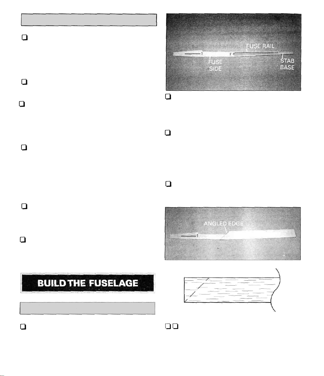
Q 2. Use two of the 1/8"x 1/4" x 24" balsa sticks
to make the upper and lower fuse rails. Use
medium CA to glue them into position.Trim the
excess extending past the stabilizer base.
Q 3. Once the glue sets, remove the fuse side
from your building surface. Examine and add
thick CA glue to any open joints, then use your
sanding block or bar sander with medium (150grit) sandpaper to sand both sides of the
fuselage side smooth.
Ql 4. Repeat steps 1 through 3 to build another
fuse side.
1-.1 C.Test fit the hinge into the slot. If the hinge
is difficult to push in, re-insert the knife and
move it back and forth in the slot a few times to
enlarge the slot.
Q 3. Insert the hinges into the slots and test fit
the rudder and elevator to the fin and stabilizer.
Do not glue the hinges until after you have
covered the model.
FUSE SIDE CONSTRUCTION
Q 1. Locate the die-cut 1/8" balsa stabilizer
bases and fuse sides. Drill two 1/4" holes in
the fuselage sides at the punch marks. Pin one
side and one base over their appropriate
locations on the plan.
Q Q 5. Select four of the hardest 1/16" x 3" x
24" balsa sheets to be used for the fuse sides.
Cut a 45° on one of the 1/16" x 3" x 24" sheets.
Use a straightedge to true up the longer edge of
the sheet. Align the bottom fuse rail with the
10
Page 11

trued edge. Apply medium CA to the fuse side
where the sheet will contact it. Place the sheet
onto the fuse side.
FUSE STRUCTURE
ASSEMBLY
Q Q 6. From another 1/16" x 3" x 24" balsa
sheet, trim an angle on an end close to 45°, but
not quite. Test fit the piece against the first, and
make sure the sheet fully covers the forward
fuse side. Glue the sheet to the fuse side using
medium CA.
QQ7.Trim the excess sheeting from around the
fuse side. Drill the 1/4" holes made in the
fuselage sides through the 1/16" sheeting. Use
150-grit sandpaper to sand the sheeting flush
with the edges of the fuse side. Use your
sanding block or bar sander with medium (150grit) sandpaper to sand the sheeting smooth.
Q 1.Test fit the die-cut 1/8" ply former F2 in
place on the right fuse side. Position the tab
on the former so it faces the bottom of the
fuselage. Press it down into its slot and use a
90° triangle to keep it perpendicular to the fuse
side. Glue it in place with medium CA.
Q 2. Test fit the die-cut 1/8" ply former F3 in
place on the right fuse side. Press it down into
its slot and use a 90° triangle to keep it
perpendicular to the fuse side. Glue it in place
with medium CA.
Q 3. Position the left fuselage side onto the
formers. Use medium CA and glue the fuse side
to the formers.
Q 4.Tape a piece of wax paper or Plan Protector
over the fuselage top view on the plan.
Q 8. Repeat steps 5 through 7 for the remaining
fuse side. Make sure to make both a left
and right side.
Q 5. Test fit the die-cut 1/8" ply former F1 in
place at the front of the fuse sides. After
checking the alignment of the fuselage to the
plan, glue former F1 to the fuse sides using
medium CA.
11
Page 12

I-] 6. Locate the die-cut 1/8" ply forward fuse
bottom. Place the forward fuse bottom onto
the fuselage. Set the fuselage assembly upright
(in its normal position) on the waxed paper.
With everything in its proper place, apply thin
CA glue to all the joints, around the formers and
along the bottom. Keep checking the parts fit
and alignment as you glue. Wait a minute for
the glue to set, then apply thick CA to the joints
to make sure a good bond exists, especially in
the joints that do not fit perfectly. Note:The use
of CA accelerator will be helpful when using
thick CA to fill any large gaps.
Q 9. Cut two 7" long pieces from the 3/16" x
3/16" x 24" balsa stick. Glue the pieces to the
upper inside edge of the fuselage in front of F2
using medium CA.
Q 10. Once the glue sets, use your sanding
block or bar sander with medium (150-grit)
sandpaper to sand the sticks smooth.
Q 11. From the 3/32" x 3" x 36" balsa sheet, cut
and glue pieces of cross-grain sheeting to the
top of the fuse from F1 to F2. Save the
remaining sheet for the aft top of the fuselage.
Qi 7. Pull the fuse sides together at the tail end
of the fuselage. Use a T-pin to pin the sides
together and check the alignment. Once the
alignment is correct, use thin CA to glue the
very aft edge together.
Q 8. Place the die-cut 1/8" ply former F4 into
position using the plan to determine its
position. While holding the sides against F4, use
medium CA to secure the former to the sides.
Q 12. Use a piece of 3/32" x 3" x 24" balsa to
sheet the bottom of the fuselage from the aft
edge of the ply fuse bottom to the end of the
fuse. Use the plan to keep the alignment of the
fuselage while sheeting. Once the glue sets, trim
the excess sheet from the edges of the fuselage
using a hobby knife. Use your sanding block or
bar sander with medium (150-grit) sandpaper to
sand the sheet smooth with the sides.
12
Page 13

Q 13. Use medium CA to glue two pieces of
3/16" x 3/16" balsa stick into the corners
between the fuse bottom and the fuse side
between formers F2 and F3. Use medium CA to
glue two more pieces of 3/16" x 3/16" balsa stick
between formers F2 and F3 along the upper
edge of the wing saddle as shown on the plan
side view.
Q 14. Use medium CA to glue the 1-3/4" x 1-3/4"
x 1-1/2" balsa nose block onto the front of the
fuselage.
Q 15. From the remaining piece of 3/32" x 3" x
36" balsa, sheet the top of the fuselage from
former F3 to the front of the stab saddle.This is
one piece of sheeting, with the grain running
from the front to the rear of the fuse. Once the
glue sets, trim the excess sheet from the edges
of the fuselage using a hobby knife. Use your
sanding block or bar sander with medium (150grit) sandpaper to sand the sheet even with
the sides.
sandpaper, round the corners of the fuselage to
the shape shown on the cross-sections of the
formers on the plan. Shape the nose block to
the shape as shown on the plan.
PREPARING THE CANOPY
Q 1. Draw the outline of the canopy onto the
fuselage using the plan as a guide. Use a hobby
knife and/or razor saw to carefully cut the
canopy from the fuselage.
Q 2. Use your sanding block or bar sander with
medium (150-grit) sandpaper to sand the edges
of the canopy and fuselage smooth. Use
caution not to remove an excess amount of
material, or the fit between the canopy and
fuselage will be loose.
Q 16. Using a razor plane and your sanding
block or bar sander with medium (150-grit)
3. From the remaining 3/16" x 3/16" balsa, cut
two 3/4" pieces which will extend 1/4" to 1/2"
forward of the canopy to act as locking pins.
13
Page 14

Note: The Daydream wing, much like the
fuselage, is designed with simplicity and ease
of building in mind. Always remember to test fit
parts before using glue to make any
adjustments for the best possible fit.
Q Q 1. Cut the "right wing panel" section
from the plan and tape it on your building
board. Tape a piece of wax paper or Plan
Protector over the plan.
Q LJ 2. Locate one of the 1/16" x 3" x 24" balsa
leading edge sheets. Use a straightedge to
true up one edge of the sheet. Align the end of
the sheet with the outer R2 wing rib, and the aft
edge of the sheet along the aft edge of the spar.
Pin the sheet into position.
Q Q 3. Locate one of the 1/8" x 3/8" x 24"
basswood spars. Using the spar location from
the plan, glue the spar to the sheet using
medium CA.
Q Q 4. Pin one of the 1/16" x 1-1/4" x 24" balsa
trailing edge sheets in its proper location.
Mark the positions of the R1 Ribs on both the
trailing edge sheet and the spar.
Ql Q 5. Add the center sheeting between the
trailing edge sheeting and spar using 1/16" x 3"
x 24" balsa. The sheeting is located only under
the R1 Ribs.
Q Q 6. Remove the die-cut 1/16" balsa wing
ribs R1 and R2 from the die-cut sheets. Slide
the wing ribs into position on the bottom spar.
QQ17. Use the die-cut 1/8" ply dihedral gauge
to set the angle of the root rib. Use thin CA to
glue the R1 and R2 ribs to the spar and trailing
edge sheeting. Note: Do not glue the ribs to the
leading edge sheeting at this time.
Q Q 8. Locate another of the 1/8" x 3/8" x 24"
basswood spars. Glue the spar into the top rib
notches using medium CA.
Q Q 9. Trim a piece of 1/16" x 3" x 24" balsa
sheet to a width of 2-5/16". Use this sheet to
make the shear webs. With the panel held flat
on the table, use medium CA to glue the balsa
shear webs to the spars, between all the ribs
in front of the spars. Notice there are shear
webs on both sides of the spars between the
R1 ribs and only in front of the spars between
the remainder of the ribs.
Note:
The
function of the shear webs is to keep
the
spars
from
collapsing.They
14
will
not need
to
Page 15

touch or be glued to the ribs. They should be
thoroughly glued to the spars.
Q Q 10. Remove the pins holding the wing
panel to your building surface. Slowly lift the
trailing edge up off the plan, rolling the wing
onto the front part of the wing ribs. The rolling
process is to push the sheeting against the wing
ribs, allowing you to glue the sheeting to the
ribs using thin CA.
QQ 11. Once the glue sets, align the wing panel
back onto the plan. Use medium CA to glue a
1/16" x 1-1/4" x 24" balsa top trailing edge sheet
into position. Glue a 1/16" x 3" x 24" balsa top
leading edge sheet onto the spar and the front
area of the wing ribs.
a hobby knife or razor saw. Use your sanding
block or bar sander with medium (150-grit)
sandpaper to sand the sheeting and the leading
edges smooth.
14. Using a Hobby Knife, remove the
section of the tip R2 rib between the spars.
QQ15. Place the center panel onto the plan
aligning the R2 rib to the plan. Block the pane
up so the center is 3" from the building surface
Q Q 12. Sheet the center-section area between
the trailing edge sheeting and spar using 1/16"
x 3" x 24" balsa sheeting.
QQ 13. Remove the center panel from the plan.
Cut the sheeting and the leading edges flush
with the outer edges of the R1 and R2 ribs using
QQ16.
its
Place a 1/8"
location
x 3/8" x
24"
on the plan and cut
balsa
it
to
spar
length.
the criss-cross pin technique shown in the
illustration to pin the spar in 3 or 4 places. The
end of the spar must be sanded to fit tightly
against the spar on the center panel.
QQ 17. Insert the narrow end of the die-cut 1/8
ply tip dihedral brace into the opening which
you previously cut between the spars in the
center wing panel. Do not glue the brace a
this time.
QQ18. Pin one of the 1/16" x 1-1/4" x 24" balsa
trailing edge sheets in its proper location.
15
over
Using
Page 16

Q Q 19. Remove the die-cut 1/16" balsa wing
ribs R3 through R10 from the die-cut sheets.
Slide the wing ribs into position on the
bottom spar Glue the wing ribs to the spar
and TE sheeting using medium CA. Glue the
R3A and R3B wing ribs to the R2 rib of the
center panel using medium CA.
Q Q 20. Use thin CA to glue the tip dihedral
brace to the spars in both the center and tip
wing panels. Use medium CA to fill any gaps
between the spar and dihedral brace.This must
be a very strong glue joint.
on the table, use medium CA to glue the balsa
shear webs to the front and back of the spars,
between the R3 and R4 ribs, and to the front of
the spars from R4 to R8.
Q Q 24. Cut a 1/4" x 1/2" x 24" balsa leading
edge to length for the center panel. Align the
bottom of the leading edge to the bottom of the
wing sheeting. Use medium CA to glue the
leading edge to the ribs and sheeting on center
panel. Cut another 1/4" x 1/2" x 24" balsa
leading edge to length, allowing it to extend 1"
past the wing tip rib R10. Sand the end of the LE
so it fits against the LE on the center panel
without any gaps. Align the LE to the bottom of
the ribs on the outer panel and glue it into
position using medium CA.
Q Q 25. Cut both of the wing tips using a 3/32"
x 3" x 24" balsa sheet.
Q t-l 21. Locate another of the 1/8" x 3/8" x 24"
balsa spars. Cut the spar to length. Glue the
spar into the top rib notches using medium CA.
Q 0 22.Trim a 1/16" x 1-1/4" x 24" balsa trailing
edge sheet to length. Use medium CA to glue
the sheet into position on the top of the ribs.
Q Q 23. Trim a piece of 1/16" x 3" x 24" balsa
sheet to a width of 2-5/16". Use this sheet to
make the shear webs. With the panel held flat
Q LI 26. Use medium CA to glue the wing tip
into position. The wing tip is aligned with the
bottom of the wing. Add the bracing using the
remaining 3/32" x 3" x 24" balsa sheet.
Q Q 27. From the remaining 3/32" x 3" x 24"
balsa sheet, make the gussets for the wing tip
panels. Using the plan as a guide, glue the
gussets into place using medium CA.
16
Page 17

Q Q 28. Use a razor plane and medium (150grit) sandpaper to sand the leading edge to
shape. Use the die-cut LE gauges to check the
shape of the leading edge as you work. Sand
the tip section LE to match the die-cut 1/8" balsa
tip LE gauge, and the center-section LE to
match the die-cut 1/8" ply center LE gauge.
Q 29. Repeat steps 1 through 28 to buiid the left
wing panel.
Q 2. Use a flat blade screwdriver to knock out the
center of the second R1 ribs between the spars.
Q 3. Locate and glue the two die-cut 1/8" ply
center dihedral braces together using
medium CA or 6-minute epoxy.
Note: In preparation for the next step, protect
your work surface by covering it with waxed
paper or Plan Protector.
Q 1. Remove the material from R1 between the
spars using a hobby knife.
Q 4. Test fit the center dihedral brace into each
wing panel. Make any adjustments necessary to
allow the wing panels to slide completely
17
Page 18

together with the brace installed. Once the
brace fits, use 30-minute epoxy to liberally
cover the brace and the two R1 ribs. Also coat
the spars inside the wing by applying epoxy
with a stick. There should be enough epoxy that
it will "ooze" out of the center of the wing
panels. This excess epoxy can be cleaned up
using a paper towel and isopropyi alcohol. Use
masking tape to hold the two panels together
until the epoxy has cured.
Note: The correct amount of dihedral between
the two center panels can be measured by
placing one center panel flat on the work
surface.The other center panel, when measured
where it attaches to the tip panel, will measure
about 3" from the work surface.This measurement
is not critical, and can vary up to 1/4" either
direction without causing any flight performance
problems.
Q 5. Once the epoxy has fully cured, use 150grit sandpaper to sand the joint between the
two panels smooth.
Q 6. Cut two scraps of 1/8" plywood to be used
as a trailing edge support. This will prevent the
rubber bands from crushing the trailing edge of
the wing. Use the plan as a guide for cutting
and positioning the support.
Q 2.Temporarily install the two 3-1/2" wing hold
down dowels in the fuselage. Set the wing on
the fuselage and secure it by hooking a couple
of rubber bands (not included) over the forward
dowel, stretching the rubber bands over the
wing and hooking them over the aft dowel. Set
the stabilizer in the stabilizer saddle. Check the
alignment of the stabilizer with the wing from
the front and rear of the model. If the stabilizer
tips are not equidistant above the wing,
carefully sand the high side of the stabilizer
saddle until the stabilizer and wing are aligned.
Use a tape measure to set the stabilizer tips
equal distances from the nose.
Q 3. UseT-pins to hold the stabilizer in position
on the fuselage while marking the bottom of the
stabilizer where it meets the fuselage. Do not
glue it in position at this time.
LJ 1. With the fuse placed right side up on a flat
surface, test fit the wing into the wing saddle. If
the wing is slightly too large (front to rear) to fit
into the wing saddle, sand the rear edge of the
saddle and the wing trailing edge slightly until
it fits.
Q 1. Carve and sand the 1/2" x 2" x 2-1/2" balsa
front wing fairing to fit the top of the wing.
Round the corners of the block to match the
fuselage.
Note: It is difficult (and not necessary) to try to
carve this block to mate exactly with the wing;
therefore, you should just "rough it out," then
later you can fill any gaps with balsa filler.
18
Page 19

Do not confuse this procedure with "checking
the C.G."That will be discussed later in the manual.
Now that the model is nearly completed, you
should balance it laterally (side-to-side). An
airplane that is laterally balanced will track
better. Here's how:
Q 1. Temporarily attach the stabilizer, elevators,
fin, rudder and wing. Lift the model by the nose
and the bottom of the fuse near the rudder. This
will require an assistant. Do this several times.
Q 2. The wing that consistently drops indicates
the heavy side. Balance the model by adding
weight to the other wing tip.
8. Elevator bottoms, followed by the top
9.
Rudder
LE,
right side followed by the left
sid»
10. Hatch
Wing:
Tack the covering to the wing tips and leading
and trailing edges. Do not shrink the covering
until after the wing is completely covered.
1. Tips of wing
2. Trailing edges of wing
3. Bottom of both wing halves
4. Top of both wing root halves (extend the
covering 1/4" past rib W-4 and tack it to the
outboard face of the rib)
5. Top of both wing tip halves
After the wing is completely covered, shrink the
covering on the bottom of the wing, keeping the
wing as straight as possible. Next, place the
wing
root panel against a flat
building
surface
while shrinking the top covering.
Once the root panels are done, place a tip panel
on a flat surface. While holding the
wing
firmly
against the flat surface, shrink the top covering
This will prevent any "washout" in the tip panels
Make sure that all the surfaces to be covered
have been sanded to remove any irregularities.
The Dynaflite Daydream can be covered with
Top Flite MonoKote® or EconoKote" film, using
the suggested covering sequence that follows."
Suggested Covering Sequence
Fuselage and Tail:
1. Fuselage bottom
2. Fuselage right side
3. Fuselage left side
4. Fuselage top
5. FinTE, followed by the fin sides
6. StabilizerTE, followed by the bottom and top
(only cover the bottom of the stabilizer
up to the marks where the fuselage
meets the stabilizer)
7. Elevator LE and root ends
After all the covering on the wing has bee
shrunk, and you have double-checked the
panels, iron the covering to each wing rib.
Q
1.
Center
and glue the
two
3-3/4"
wing
down dowels in the fuselage.
Q 2. Set the wing on the fuselage and secure
to the fuselage by hooking a couple of #6
rubber bands (not included) over the forward
dowel, stretching the rubber bands over the
wing and hooking them over the aft dowel
Again, set the stabilizer in the stabilizer saddle
Check the alignment of the stabilizer with the
wing from the front and rear of the model.
19
bottom
hold
Use
Page 20

a tape measure to set the stabilizer tips equal
distance from the nose.
Q 9. Follow the same procedure to install the
rudder on the fin.
Q 3. Use 30-minute epoxy to glue the stabilizer
in position on the fuselage, rechecking the
alignment before the epoxy cures.
Q 4. Remove the covering from the bottom of
the fin. Test fit the fin onto the stabilizer. The
trailing edge of the fin should align with the
trailing edge of the stabilizer. When satisfied
with the fit, glue the fin to the stabilizer with
6-minute epoxy or aliphatic resin. Make sure
the fin is 90° to the stabilizer. Masking tape and
T-pins can be used to hold it in place.
Q 5. Starting with the elevators and stab, cut
the covering from the hinge slots.
The most common mistake made by modelers
when installing a CA type of hinge is not
applying a sufficient amount of glue to fully
secure the hinge over its entire surface area; or,
the hinge slots are very tight, restricting the
flow of CA to the back of the hinges.This results
in hinges that are only "tack glued"
approximately 1/8" to 1/4" into the hinge slots.
The following technique has been developed to
help ensure thorough and secure gluing.
D 6. It is best to leave a very slight hinge gap,
rather than closing it up tight, to help prevent
the CA from wicking along the hinge line. Make
sure the
control
surfaces
will
deflect
to
the
recommended throws without binding. If you
have cut your hinge slots too deep, the hinges
may slide in too far, leaving only a small portion
of the hinge in the control surface.To avoid this,
you may insert a small pin through the center of
each
hinge before installing. This
pin
will
keep
the hinge centered while you install the control
surfaces.
I—17. Install the hinges in the elevator and attach
the elevator to the stabilizer.
Q 8. Apply 6 drops of thin CA adhesive to both
sides of each hinge. Allow a few seconds
between drops for the CA to wick into the slot.
Q 10. Reinstall the control horns.
Q 11. Use aT-pin inserted through the tow hook
block from the inside of the fuselage to locate
the tow hook pilot holes.Thread a 4-40 nut onto
the tow hook. Then, thread the tow hook into
the tow hook block from the bottom of the
fuselage to the depth shown on the plan.
Ql 1. From the remaining 3/16" x 3/8" basswood
spar, cut three servo rails. The rails should be
snug against the fuselage sides, but not so tight
that they cause the fuselage sides to bow
outward.
Q Q 2. Slide the first servo rail into its slot in the
fuselage doubler. Slide it all the way forward
and glue it in place with thick CA. Slide the
second servo rail into place and then slide it all
the way aft. Do not glue it yet! Position one
of your servos in place and use it to position the
second servo rail. Do not push the rear servo
rail tight against the servo, but rather leave
about a 3/32" gap between the.servo "body"
and the servo rail. This will provide enough
room to install and remove the servos without
removing the rails. Glue the second servo rail in
place. Repeat the step for the second servo to
position and glue the third servo rail.
20
Page 21

Q 3. Install the servos using the hardware included
with your radio system. Use the plan as a guide
to position the servos laterally in the fuselage.
Q4. Install the receiver, battery and switch. Use
foam to cushion the receiver and battery.
Q 1. Hold the nylon control horns on the
elevator and rudder in the positions shown on
the plan and mark the mounting hole locations.
Drill 3/32" diameter holes at these locations.
Q 2. Harden the balsa in the area of the
control horns (on both sides of the control
surfaces) by poking several holes with a pin,
then apply thin CA glue. Sand smooth.
Ql 3. Mount the horns with 2-56 screws and the
nylon backing plates which were attached to
the horns.
4.
Use a hobby knife to
sharpen
one end
of
a piece of 3/16" (outside diameter) brass tubing,
then use this tubing to cut the pushrod exit holes
(you may use a 3/16" drill bit, but the brass tube
method gives a much neater cut). Determine
the location of these holes from the plan.
Q Q 5. Insert the plastic pushrod tubes through
the holes you just cut. Route the pushrod tubes
according to the plan. Keep the tubes as
straight as possible. Glue the tubes to the fuse
sides at the rear exit points using thin CA glue.
Q Q 6. Cut off the tubes at the exit points and
sand them flush with the fuse sides using a
sanding
block.
Use
balsa
filler to
fill
any
gaps
between the tubes and fuse sides.
Q Q 7. Thread one of the 2-56 x 1 threaded
rods into one of the nylon pushrods.Thread a
nylon clevis 14 turns onto the threaded rod.
Slide the pushrod into the tube from the rear of
the fuselage. Attach the clevis onto the appropriate
control horn.
[-I Q 8.Thread another nylon clevis onto another
threaded rod. Attach the clevis onto the servo
21
Page 22

arm. Trim the nylon pushrod 1/2" ahead of the
threaded rod.This will allow the threaded rod to
be securely attached. Remove the clevis from
the servo arm and thread the rod into the nylon
pushrod. Reattach the clevis to the servo arm.
0 9. Repeat steps 4 through 8 for the remaining
pushrod assembly.
Q 10. Once the pushrods are fully installed, use
the remaining 3/16" x 3/16" balsa to make
supports for the pushrod tubes. Place the
supports in the fuselage towards the leading
edge and trailing edge of the wing. The
supports will reduce the amount of flex in the
pushrods and result in more accurate inputs.
Q 1. Drill a 1/8" hole in the bottom of the fuse as
shown on the plan for the tow hook attachment.
Install a 4-40 blind nut into the hole from the
inside of the fuselage.
RADIO SETTINGS
RADIO SET-UP
ELEVATOR MOVES UP
RUDDER MOVES RIGHT
Use the sketch to make sure the control
surfaces are moving the correct directions.
The control throws are as follows:
Elevator:
Rudder:
3/8" up
1-5/8" left
3/8" down
1-5/8" right
Q 2. Attach the threaded tow hook to the
bottom of the fuselage by threading a 4-40 nut
and a 4-40 washer all the way onto the tow
hook and screwing the tow hook into the blind
nut. With the tow hook threaded almost all the
way into the blind nut, make sure the tow hook
is facing straight back and tighten the nut to
secure it.
A piece of self-adhesive foam rubber weather
stripping can be applied to the front of the
fuselage bottom to help protect it from getting
nicked during landings.
The canopy is held in place with a rubber band.
Use a medium-size rubber band to hold the
canopy in position as shown on the plan.
Note: This section is VERY important and
must not be omitted! A model that is not
properly balanced will be unstable and possibly
unflyable.
22
Page 23

2-5/8" [67mm]
The balance point (C.G. - Center of Gravity) is
located under the spar. This is the balance point
at which your model should balance for your
first flights. Later, you may wish to shift the
balance up to 3/8" behind the spar to change
the flying characteristics. Moving the C.G.
forward of the spar will add some stability but
it will decrease the overall performance of the
sailplane and make it stall easier at slower
speeds. Moving the balance behind the spar
makes the model more agile with a lighter and
snappier "feel" and improves the sailplane's
response to air currents. It also makes the
model less stable and can cause the sailplane
to "tuck under" or dive when its flying speed
increases. If you fly the Daydream with its C.G.
behind the spar (usually only contest flying),
pay close attention and do not let it gain
excessive speed. If it does tuck under and you
have plenty of altitude, give the plane a little
down elevator and allow it to go on under.
When it starts to climb up the back of the
"outside loop" its airspeed will drop and you
can pull out with some up elevator or roll out
with full rudder. If you don't have plenty of
altitude, gently pull out with up elevator but be
careful and don't "force" it up or you may
over stress the wing.
With the wing attached to the fuselage, and all
parts of the model installed (ready to fly), lift the
model by picking it up with a finger on each
bottom inner spar. If the tail drops when you lift,
the model is "tail heavy" and you must add
weight to the nose to balance. If the nose drops,
it is "nose heavy" and you must add weight to
the tail to balance.The model should hang with
a slight nose down attitude. Add lead to the
front of the fuselage to correct a tail heavy
model. Getting the weight farther back helps
correct the "nose heaviness."
This is a very important step and should
be done occasionally throughout the
flying season. A sailplane's wing is most
efficient when it is not twisted or warped at all.
"Washout" (wing trailing edges twisted up at
the tip) helps make a poor wing design fly
better by adding some stability (preventing
stalls) at slow speeds but it cuts down on the
wing efficiency at normal speeds. The
Daydream's wing is designed to fly well at slow
speeds without any washout, and therefore we
recommend you check to make sure the wings
are "flat" using the following procedure:
Set the wing so an inner panel is resting on a
flat surface. Any warp (twist) will show up by
causing a corner of the panel to rise off the
work surface.
To remove the warp, gently twist the wing in the
opposite direction while a helper glides an iron
or heat gun over the covering on both the top
and the bottom of the panel to re-shrink the
covering. Hold the twist until the covering cools
and then recheck for warps. It may take several
tries to get a warp out but it is worth it as you
will end up with a sailplane that flies straight
and true and responds to air currents like a high
performance sailplane should.
Follow the same procedure to check all four
wing panels and then go back and double check
them. Sometimes you put a warp in one panel
while trying to fix another. You should also look
at the tail surfaces as they too can warp.
23
Page 24

CHARGE THE BATTERIES
Follow the battery charging procedures in your
radio instruction manual. You should always
charge your transmitter and receiver batteries
the night before you go flying, and at other
times as recommended by the radio manufacturer.
FIND A SAFE PLACE TO FLY
This means with the
collapsed and the receiver and transmitter on,
you should be able to walk at least 100 feet
away from the model and still have control. Have
someone help you. Have them stand by your
model and, while you work the controls, tell you
what the various control surfaces are doing.
Read and abide by the following Academy of
Model Aeronautics Official Safety Code:
transmitter antenna
The best place to fly your R/C model is an AMA
(Academy of Model Aeronautics) chartered club
field. Ask your hobby shop dealer if there is
such a club in your area and join. Club fields are
set up for R/C flying which makes your outing
safer and more enjoyable.The AMA can also tell
you the name of a club in your area. We
recommend that you join AMA and a local club
so
you can have a safe place to fly and also
have insurance to cover you in case of a flying
accident. (The AMA address is listed on page 3
of this instruction book.)
If a club and its flying site are not available, you
need to find a large, grassy area at least 6 miles
away from any other R/C radio operation and
away from houses, buildings and streets. A
schoolyard may look inviting but it is usually
too close to people, power lines and possible
radio interference.
If you are not thoroughly familiar with the
operation of R/C models, ask an experienced
modeler to check to see that you have the radio
installed correctly and that all the control
surfaces do what they are supposed to.
RANGE CHECKTHE RADIO
GENERAL
1. I will not fly my model aircraft in competition
or in the presence of spectators until it has been
proven to be airworthy by having been
previously successfully flight tested.
2. I will not fly my model aircraft higher than
approximately 400 feet within 3 miles of an
airport without notifying the airport operator. I
will give right of way to, and avoid flying in the
proximity of full scale aircraft. Where necessary
an observer shall be utilized to supervise flying
to avoid having models fly in the proximity of
full scale aircraft.
3. Where established, I will abide by the safety
rules for the flying site I use, and I will not
willfully and deliberately fly my models in a
careless, reckless and/or dangerous manner.
RADIO CONTROL
1. I will have completed a successful radio
equipment ground check before the first flight
of a new or repaired model.
2.1 will not fly my model aircraft in the presence
of spectators until I become a qualified flyer,
unless assisted by an experienced helper.
Wherever you do fly, you need to check the
operation of the radio before every time you fly.
3. I will perform my initial turn after takeoff
away from the pit, spectator and parking areas,
24
Page 25

and I will not thereafter perform maneuvers,
flights of any sort or landing approaches over a
pit, spectator or parking area.
forward. The plane should be launched with a
gentle push forward. With a little practice you
will be able to launch it just the right speed so it
soars straight ahead in a long and impressive
glide path. Adjust the trims on your transmitter
to get the plane to fly straight ahead in a smooth
glide path.
First of all, if you are flying with other
flyers, check to make sure they are not
flying or testing on the same frequency as
your model.
Try to find an experienced pilot to help
you with your first flights. Although the
Daydream is very easy to fly, an experienced
pilot can save you a lot of time and possible
aggravation by helping you get your model in
the air and properly trimmed.
It is a good idea to do a couple of trim flights
before each flying session to make sure the
plane is still in trim and the radio is working
properly.The model will survive a hard landing
from 5 feet much better than it will one from
several hundred feet. The first few trim flights
should be done over a grass field. The longer
the grass the better (more cushion).
Turn on the transmitter first and then the
receiver and hold the Daydream under the wing
with the nose pointed slightly down and
directly into the wind. It is very important that
you launch the model with the wings level and
the nose pointing at a spot on the ground about
50 feet in front of you. Have a friend stand off to
the side of you and tell you whether the nose is
pointing up or down. If the sailplane is launched
with the nose up or launched too hard it will
climb a few feet, stall and fall nose first straight
down. With the nose pointed down slightly the
sailplane will accelerate down until it picks up
enough flying speed then level off and glide
Once you get the hang of launching it you can
try turning the plane during the trim flights by
gently applying a "touch" of right or left rudder.
You can also try "flaring" the landings by
slowly applying a touch of up elevator (pull the
stick back) as the plane nears the ground. The
Daydream will continue to fly just a few inches
off the ground for a surprisingly long distance.
It is important you don't "over-control" the
model. Make any control inputs slowly and
smoothly rather than moving the transmitter
sticks abruptly.
A hi-start is the most popular way to launch
your Daydream. It consists of 25' - 100' of
rubber tubing and 200' - 400' of string with a
parachute or streamer at the end. One end of
the rubber is staked down directly upwind of
the launch point. One end of the string is
attached to the other end of the rubber and the
end of the string with the parachute has a loop
or ring and is attached to the tow hook on the
sailplane.
Follow the directions that came with the hi-start
and lay it out directly into the wind. Place the stake
at the far upwind edge of the flying field so the
parachute will blow back onto the flying field.
Turn on your transmitter and then your receiver
and hook the parachute onto your plane's tow
hook. Pull the plane back approximately twice
as far as the rubber is long (i.e. 100' of rubber =
pull back 200') or whatever the hi-start
instructions state. A "fish scale" is handy for
determining the correct amount of pull. For
25
Page 26

your first flights pull the plane back until there
is approximately 8 Ibs. of tension. More tension
can be used after you get acquainted with the
launching procedure.
Hold the plane above your head with the
wings level and the nose pointed slightly up
and directly into the wind. Give the plane a
healthy push forward to get it flying and it will
climb up like a kite. You should not have to
touch the elevator during the launch but use the
rudder stick to keep it going straight up. As the
rubber relaxes the plane will fly off the hi-start
and the parachute will bring the end of the
string back towards you.
Find a BIG, OPEN field for your first flights. The
bigger the better as you won't have to worry
about where you need to land. Ground based
objects (trees, poles, buildings, etc.) seem to
attract model airplanes like a magnet. Again,
we would like to recommend that you find
an experienced pilot to help you with
these first flights.
Note: You need to remember that your
radio control responds as if you were
sitting in the cockpit. When you push the
transmitter stick to the right, the rudder
moves to the plane's right! This means
that when the plane is flying towards you
it may seem like the rudder controls are
reversed (when you give "right" rudder
the plane turns to your left-which is the
plane's "right"). It is sometimes easier to
learn to fly the plane if you always face your
body in the direction the plane is flying and look
over your shoulder to watch the model,
Don't worry about accomplishing very much on
your first flights. Use these flights to get the
"feel" of the controls and the Daydream's flying
characteristics. Try to keep the plane upwind
and Just perform some gentle S-turns (always
turning into the wind) until it is time to set up
for landing. Have a helper adjust the trims on
your transmitter (a little at a time) until the
plane will fly straight and level with the
transmitter sticks in their neutral positions. It
can be very hard for a beginner to fly a plane
straight towards him as he would have to do if
the plane were downwind and every mistake
takes the plane a little farther downwind. When
it is time to land, just continue performing the
gentle S-turns upwind and let the plane glide
onto the ground. Don't worry about where the
plane lands -just miss any trees, etc.
Practice flying directly into the wind (upwind of
yourself) without letting the plane get off
course, and then turn and come downwind until
the plane is even with you and try it again.
When you are comfortable with flying directly
into the wind, start letting the plane go behind
you (downwind) a little before you start back
upwind. Continue this until you can fly directly
towards you from downwind without getting
disoriented. At this point you can start to
establish a "landing pattern" and bring the
sailplane in for a landing from downwind. This
enables the plane to be flown as slowly (ground
speed) as possible for accurate landings.
Thermal soaring is one of the most intriguing of
all aspects of flying and the Daydream was
designed to excel at thermal soaring even in the
hands of a novice. It can be hard for the average
person to understand how a plane can fly for
hours and gain altitude without a motor.
26
Page 27

Thermals are a natural phenomenon that
happen outside, by the millions, every single
day of the year. Thermals are responsible for
many things including forming several types of
clouds, creating breezes, and distributing plant
seeds and pollen. If you have ever seen a dust
devil (which is nothing more than a thermal that
has picked up some dust), you have seen a
thermal in action. Their swirling action is very
similar to that of a tornado's but of course much
gentler. Most thermals have updrafts rising in
the 200-700 feet per minute range but they have
been known to produce updrafts of over 5,000
feet per minute (that's over 50 miles/hour
straight up!) These strong thermals can rip a
plane apart or carry the plane out of sight
before the pilot can get out of the updraft.
Thermals are formed by the uneven heating of
the earth and buildings, etc. by the sun. The
darker colored surfaces absorb heat faster than
the lighter colors which reflect a great deal of
the sun's energy back into space. These darker
areas (plowed fields, asphalt parking lots, tar
roofs, etc.) get warmer than the lighter areas
(lakes, grassy fields, forests, etc.). This causes
the air above the darker areas to be warmer
than the air over the lighter areas and the more
buoyant warm air rises as the cooler, denser air
forces its way underneath the warmer air. As
this warm air is forced upward it contacts the
cooler air of the higher altitudes and this larger
temperature difference makes the thermal rise
quicker. The thermal is gradually cooled by the
surrounding cooler air and its strength
diminishes. Eventually the thermal stops rising
and any moisture contained in the once warm
air condenses and forms a puffy cumulus cloud.
These clouds, which mark the tops of thermals,
are usually between 2000 and 5000 feet high.
It takes a lot of concentration to thermal soar
effectively. A sailplane can fly along the edge of
a thermal and unless the pilot is carefully
watching the model he may not realize the
opportunity to gain some altitude. Because
most thermals are relatively small (a couple
hundred feet in diameter or less at 400' altitude)
compared to the rest of the sky, the sailplanes
will rarely fly directly into the thermal and start
rising. Generally, the sailplane will fly into the
edge or near a thermal and the effects the
thermal has on the plane may be almost
unnoticeable. As the sailplane approaches a
thermal, the wing tip that reaches the rising air
first will be lifted before the opposite wing tip.
This causes the plane to "bank" and turn away
from where we would like the plane to go.
When you are thermal soaring, try to fly as
smoothly and straight as possible. Trim the
plane to fly in a straight line and only touch the
controls when you have to. Watch the sailplane
carefully
and
it will
tell
you
what
it
encountering.
When the sailplane flies directly into a thermal
it will either start rising or stop sinking. Either
case is reason enough to start circling
(especially in a contest where every second
counts). Fly straight ahead until you feel like
you are in the strongest lift, fly a couple of
seconds farther (so your circle will be
centered in the strongest lift) and then start
circling in a fairly tight but smooth turn. When
the sailplane is low the turns have to be tighter
to stay in the strongest lift. As the plane gains
altitude, the turns can be larger and flatter. The
flatter the turn, the more efficient the plane is
flying, but don't be afraid to really "crank" it
into a steep bank when you are low. If you see
the plane falling off on one side of the turn,
move your circle over into the stronger lift;
Thermals move along with the wind so as you
27
is
Page 28

circle you will be swept along with it. Be careful
when thermaling that you don't get so far downwind
you
can't make it back to the field to land.
If the sailplane is flying along straight and all of
a sudden turns, let the plane continue to bank
(you may have to give it some rudder to keep it
banking) until it has turned 270° (3/4 of a full
circle). Straighten out the bank and fly into
whatever turned the plane. If you encounter lift,
and you won't every time, start circling just as
you did when flying directly into a thermal.
Thermals are generated all day long, but the
strongest thermals are produced when the sun
is directly overhead. 10:00 am - 2:00 pm seems
to be the best time to get those "killer"
thermals. Some of these thermals can be very
large and you may find it hard to get out of
them. If you find yourself getting too high, don't
dive the plane to get out of the lift. Sailplanes
are very efficient aircraft and they will build up
a lot of speed and could "blow up" in the rough
air of a thermal.The easiest way to lose altitude
is to apply full rudder and full up elevator. This
will put the plane into a tight spin that will not
over stress the airframe but it will enable it to
lose altitude very quickly. This is especially
helpful if the sailplane gets sucked into a cloud
or it gets too high to see.The twirling action will
give the sun a better chance of flashing off of
the wing and catching your attention. When you
are high enough and want to leave the thermal,
add a little down trim to pick up some speed
and fly 90° to the direction of the wind. If you
are not really high and want to find another
thermal, you may want to look upwind of the
last thermal. The same source that generated
this thermal is probably producing another.
Just watch out for "sink" which is often found
behind and between thermals.
As you might expect, with all this air rising,
there is also air sinking.This air is the sailplane
pilot's nightmare that can really make soaring
challenging. "Sink" is usually not as strong as
the thermals in the same area, but it can be very
strong. Down drafts of many hundreds of feet
per minute are common on a good soaring day.
These down drafts can make a sailplane look
like it is falling out of the air. Because of this, it
is important that you do not let the sailplane get
too far downwind.
When encountering sink, immediately turn and
fly 90° to the direction of the wind (towards you
if possible). Apply a little "down elevator" and
pick up some speed to get out of the sink as fast
as possible. Every second you stay in the sink is
precious altitude lost.
Pay Attention! - Pay close attention to the sailplanes
flying before you, watch them and try to
establish where and when the thermals are
being formed. Thermals are often formed in
cycles and can be fairly regular, so if you keep
track of the time intervals you will have a pretty
good idea of when and where a thermal may be
generated.
Watch the birds! -Thermals suck up small insects
that many birds love to eat. A bunch of
swallows flying around in one area may
indicate a thermal. Soaring birds (hawks,
vultures, eagles etc.) are the best thermal
indicators. They not only show you where the
thermal is but they also show you where the
center is. These "Masters of the sky" will often
fly right along with sailplanes.
Practice those landings! - Most thermal contests
are won or lost during the Landing. Establish a
particular landing pattern and try to stick to it
for all landings. Learn to shift your pattern to
account for the wind and particular flying field
characteristics. Spoilers can be very useful
during contest landings. They allow you to
28
Page 29

bring the sailplane in for a landing higher or
faster than normal to guard against any last
minute sink or gusts and dump the extra
altitude and speed at the last second. They can
also be used to help control your skid. Opening
the spoilers will stop the plane from sliding a
little quicker. You can also "steer" the plane
while it is sliding along the ground. Don't
expect to be able to "horse it around" but you
can gain valuable inches by using the rudder to
guide it toward the spot as it slides to a stop. Be
very careful not to "ground loop" the plane
since you will lose your landing points if the
plane flips over.
Concentrate - Keep your eye on your sailplane
during your contest flights. Have a helper or
your counter watch the other sailplanes in the
air. Sometimes your sailplane will wiggle so
quickly or gently that you may miss it if you are
not paying close attention. If you find a
productive thermal, don't leave it because your
helper tells you that someone else has found a
different one.
Know your sailplane! - Learn what your sailplane
will and won't do and fly within this envelope.
This will allow you to ride thermals downwind
while knowing when you have to head back to
make your landing safely.
Learn from the wind! - Keep track of which
way the wind is blowing. If the wind suddenly
shifts, there is some thermal action fairly close
to you. The air is probably being either sucked
up into a thermal or falling out of some sink. In
either case it is often a good idea to fly in the
direction the wind is blowing if your sailplane is
in the general area.This will take you towards a
thermal if there is one or away from the sink,
both of which are desirable.
FLYING
Slope soaring is a type of flying that is very
popular in hilly regions and along the coasts.
This type of soaring is possible when the wind
is blowing directly up a hill or cliff. As the wind
hits the slope it is forced up, producing lift
which can be utilized by real sailplanes, hang
gliders, birds and even model sailplanes.
To be able to slope soar, you need a slope with
a smooth piece of land (or water) out in front of
it and a breeze blowing pretty close to straight
up the slope.The higher and steeper the hill or
cliff the better. Also the larger and smoother the
land out in front the better.The air flowing along
hits the hill, is forced up and can generate a
very large area of lift. Behind the hill is a large
area of turbulent air that can be very dangerous
to try to fly in.The faster the wind is blowing the
stronger the lift and turbulence will be.
To fly off a slope, stand near the edge and throw
the sailplane (nose down) into the wind. As the
sailplane flies out into the "band" of lift it will
begin to gain altitude.Turn and fly parallel to the
slope and make all of your turns into the wind
(especially when you are close to the slope).
You will be surprised at the altitude you can
gain just from slope lift. Thermals will often be
"popped loose" by these slopes. If you catch a
thermal and follow it downwind, be very careful
to stay high enough to make it back to the slope
without flying through the turbulent air behind
the slope. If you don't have enough altitude you
may want to land a good distance behind the
slope if possible to avoid this turbulent air.
SLOPE LANDINGS
Landings can be very tricky on some slopes. On
gentle slopes you can often fly very close to the
29
Page 30

top of the slope and "slide" into the top of the
slope without encountering any turbulent air.
On steeper slopes you may have to be a little
more aggressive to get the plane out of the lift.
In any case it is a good idea to plan your landing
before you launch your plane.
In strong wind conditions, you may want to add
ballast (weight) to the sailplane to increase its
wing loading which increases its normal flying
speed. Increasing the weight of your sailplane
does not change its "glide ratio" but it does
make it fly faster which makes it sink a
proportional amount faster. Because of this
faster sink rate, you need to be very cautious
when ballasting for a thermal contest. In
duration type contests only use ballast on very
windy days that also have a lot of thermal
activity.
Add the weight as near as possible to the C.G.
of the plane. 4-8 oz. will make a noticeable
difference in the sailplane's flying speed and
more can be added if needed. Make sure to
recheck the C.G. of the plane after adding
ballast - it should remain where it was.
Have a ball! But always stay in control and
fly in a safe manner.
DYNAFLITE™ HI-STARTS
DYFP8301 (Standard)
DYFP8302 (Heavy Duty)
• Compact power for high-altitude launches.
• Complete systems for 2-meter and unlimited class
sailplanes.
A Dynaflite Hi-Start and 800' of clear launch area are
all you need to send your sailplane rocketing up to
500' in the air! Easy to lay out and retrieve, Hi-Starts
include everything required for sailplane launches:
100' of UV-stabilized surgical tubing, injectionmolded reel, parachute, steel stake and tow ring, and
nylon tow line. Standard Hi-Start with 1/8" diameter
tubing offers strong, steady power for 2-meter
sailplanes. Heavy-Duty Hi-Start with 3/16" diameter
tubing provides the launch power needed for
sailplanes spanning 100" or more.
GOOD LUCK AND GREAT SOARING!
Dynafilte Wanderer"
This docile, slow-flying kit gives newcomers the
response time needed for successful first flights — and
the durable, all-balsa construction required to keep
flying after a less-than-perfect landing. DYFA3901
30
Page 31

Dynafilte Talon"
No matter if the air's light and the airfield's small —
you'll be thrilled with the Talon's speed and
maneuverability. Launch it by hand, down a slope or
using a hi-start. Ailerons increase the precision of your
aerobatics.The stabilizer controls lift with minimal drag,
and can be built conventionally or as a full flying T-tail.
Wing assembly is simplified by a special, strong "D-tube"
design, and the fuselage consists of ply formers and six
preshaped balsa sides. DYFA2017
Dynafilte Skeeter"
Versatile, affordable and easy to assemble, the 55.5"
span Skeeter
will
deliver for beginners and pros
alike.
An S3021 airfoil cuts through the air to gain maximum
altitude, whether launched by hand or high start. An allwood weight of just 12 oz. allows it to thermal in a trim,
tight spiral, or make use of the gentlest breezes on the
slopes. DYFA2014
Dynaflite Bobcat"
Easy enough for anyone with rudder/elevator
experience to enjoy, the Bobcat brings together the
precise control allowed by ailerons and the stylish look
of F-3B aircraft. Spanning 78", this sailplane features a
low wing loading and a turbulated airfoil for excellent
performance at low speeds, with minimum sink. AT-tail
keeps the horizontal stab out of harm's way. The kit
assembles easily from high-quality balsa and lite
ply...and once launched, it climbs like a rocket! DYFA2016
Dynaflite Bird ofTime"
Put your sailplane experience to use on a model that
time has proven to be a winner! The unlimited class,
117" span Bird ofTime pairs refined looks with superior
performance — for example, its thin wing and light
wing loading (5.52 oz/sq ft) provide a super-low sink
rate, as well as near-legendary lift/drag rate. It's
engineered as gracefully as it performs: the slender
balsa/ply fuselage tapers toward a full-flying stabilizer,
while the 2-piece wing features a large, 5/16" wing rodand fully-sheeted "D" tube. DYFA4502
31
 Loading...