

Page 1
• F3B-style soarer makes an ideal first aileron model.
• Strong turbulated wing allows winch launching and low-speed sink.
• Rugged, lightweight balsa/life ply construction.
READ THROUGH THIS INSTRUCTION MANUAL FIRST. IT CONTAINS
IMPORTANT INSTRUCTIONS AND WARNINGS CONCERNING THE ASSEMBLY
AND USE OF THIS MODEL.
Dynaflite guarantees this kit to be free from defects in both material and workmanship at the date of
purchase. This warranty does not cover any component parts damaged by use or modification. In no
case shall Dynaflite's liability exceed the original cost of the purchased kit. Further, Dynaflite reserves
the right to change or modify this warranty without notice. In that Dynaflite has no control over the
final assembly or material used for final assembly, no liability shall be assumed nor accepted for any
damage resulting from the use by the user of the final user-assembled product. By the act of using
the user-assembled product, the user accepts all resulting liability. If you are not prepared to accept
the liability associated with the use of this product, return this kit immediately in new and unused
condition to the place of purchase.
BCATP03 Printed in USA Entire Contents © Copyright 1996
WARRANTY
Page 2
Congratulations and thank you for purchasing the
Dynaflite Bobcat. Once you have learned the basics of
thermal flying, the Bobcat is an ideal "second"
sailplane. With its "flat" wing and ailerons, the Bobcat
is more maneuverable than beginner, two-channel,
rudder-only models so you will be able to chase those
elusive thermals more aggressively. The Bobcat's
relatively thin airfoil makes it penetrate the wind for
competition flying and slope soaring, yet the flat
bottom makes it somewhat of a floater as well. You
can build the Bobcat with a steerable rudder, but only
advanced fliers will be able to take full advantage of
the additional steering capability. The instructions tell
you how to build a steerable rudder or build a fixed,
immovable rudder. You can mount micro, mini or full
size servos in the fuselage, but the ailerons require
either a mini or a micro servo. Most experts will also
use mini or micro servos in the fuselage. The generous
cabin area allows the Bobcat to accept full size,
standard configuration battery packs and receivers.
Let's get started!
2
Page 3
Your Bobcat is not a toy, but a sophisticated working
model that functions like a full-size airplane. Because
of its performance, if you do not assemble and
operate the Bobcat correctly, you could possibly injure
yourself or spectators and damage property.
To make your R/C modeling experience totally
enjoyable, we recommend that you get assistance
with assembly and your first flights from an
experienced, knowledgeable modeler. You'll learn
faster and avoid risk to your model before you're
truly ready to solo. Your local hobby shop has
information about flying clubs in your area whose
membership includes qualified instructors.
You can also contact the national Academy of Model
Aeronautics (AMA), which has more than 2,300
chartered clubs across the country. We recommend
you join the AMA which will provide you with
insurance coverage at AMA club sites and events.
AMA Membership is required at chartered club
fields where qualified flight instructors are available.
Contact the AMA at the address or toll-free phone
number below.
Academy of Model Aeronautics
5151 East Memorial Drive
Muncie.lN 47302
(800) 435-9262
Fax (317) 741-0057
1. You must assemble the plane according to the
instructions. Do not alter or modify the model, as
doing so may result in an unsafe or unflyable model.
In a few cases the instructions may differ slightly
from the photos or plan. In those instances the text
should be taken as correct.
2. You must take time to build straight, true and strong.
3. You must install all R/C and other components so
that the model operates properly on the ground and
in the
air.
4. You must test the operation of the model before the
first and each successive flight to insure that all
equipment operates correctly. You must also make
certain that the model has remained structurally sound.
NOTE: We, as the kit manufacturer, can provide
you with a quality kit and great instructions, but
ultimately the quality and flyability of your finished
model depends on how you assemble it; therefore,
we cannot in any way guarantee the performance
of your completed model and no representations
are expressed or implied as to the performance or
safety of your completed model.
Please inventory and inspect all parts carefully
before starting to build! If any parts are missing,
broken or defective or if you have any questions
about building or flying this model, please call us at
(217) 398-8970 and we'll be glad to help. If you are
calling for replacement parts, please look up the
part numbers and have them ready when calling.
3
Page 4
REQUIRED SUPPLIES
AND TOOLS
REQUIRED ACCESSORIES
These are the items "not included" with your kit, that
you will need to purchase separately. Items in
parentheses (OSMG2691) are suggested part
numbers recognized by distributors and hobby
shops and are listed for your ordering convenience.
GPM is the Great Planes® brand, TOP is the Top
Flite® brand and HCA is the Hobbico® brand.
4 Channel Aircraft Radio System with 1 or 2
standard, mini or micro servos and 1 mini or
micro servo
2-Meter Hi-Start Launch System
Approximately 2 rolls Top Flite MonoKote®
covering
1 /4" Latex Foam Rubber Padding
(HCAQ1000)
1/16" Foam Wing Seating Tape
(GPMQ4422)
#64 Rubber Bands (1 /4 Ib box - HCAQ2020)
(3 sets) 36" Flexible Cable Pushrod for
Elevator and Ailerons (GPMQ3702)
36" Solid Wire Pushrod Set (optional) for
Steerable Rudder (GPMQ3716)
(1 pc.) 2-56 Nylon Clevis (optional) for
Steerable Rudder (GPMQ3800, pkg. of 2)
(3 pcs.) Standard Solder Clevises (for .074
wire/cable) (GPMQ3810, pkg. of 2)
(1 pc.) 1/16" Threaded Ball Link for Aileron
Servo (GPMQ3842)
(2 pcs.) 2-56 Screw-Lock Pushrod Connectors
(GPMQ3870, pkg. of 2)
These are the building tools and adhesives that you
will need to build your Bobcat.
We recommend Great Planes Pro™ CA and Epoxy
2 oz. Thin CA (GPMR6003)
2 oz. Medium CA+ (GPMR6009)
CA Applicator Tips (HCAR3780)
CA Accelerator (GPMR6035)
30-Minute Pro Epoxy (GPMR6047)
#1 Hobby Knife Handle (XACR4305)
#11 Blades (Qty 100. - HCAR0311) or (Qty.
5-XACR2911)
Hobbico Builders Triangle (HCAR0480) or
similar
Medium T-pins (HCAR5150)
Wax Paper
Electric Drill
Drill
Bits:
1/16",
(or 7/64"), 11/64" (or 5/32")
#1 Phillips Screwdriver
Top Flite Covering Iron (TOPR2100)
Hot Sock'" (for your covering iron, TOPR2175)
Single-edge Razor Blades (100, HCAR0312)
Denatured or IsopropyI Alcohol (for epoxy
clean-up)
HobbyLite" Balsa Filler (HCAR3401)
Bar Sander or Sanding Block and Sandpaper
3/32",
5/32",
3/16",
#36
(coarse, medium, fine grit - see next page)
4
Page 5
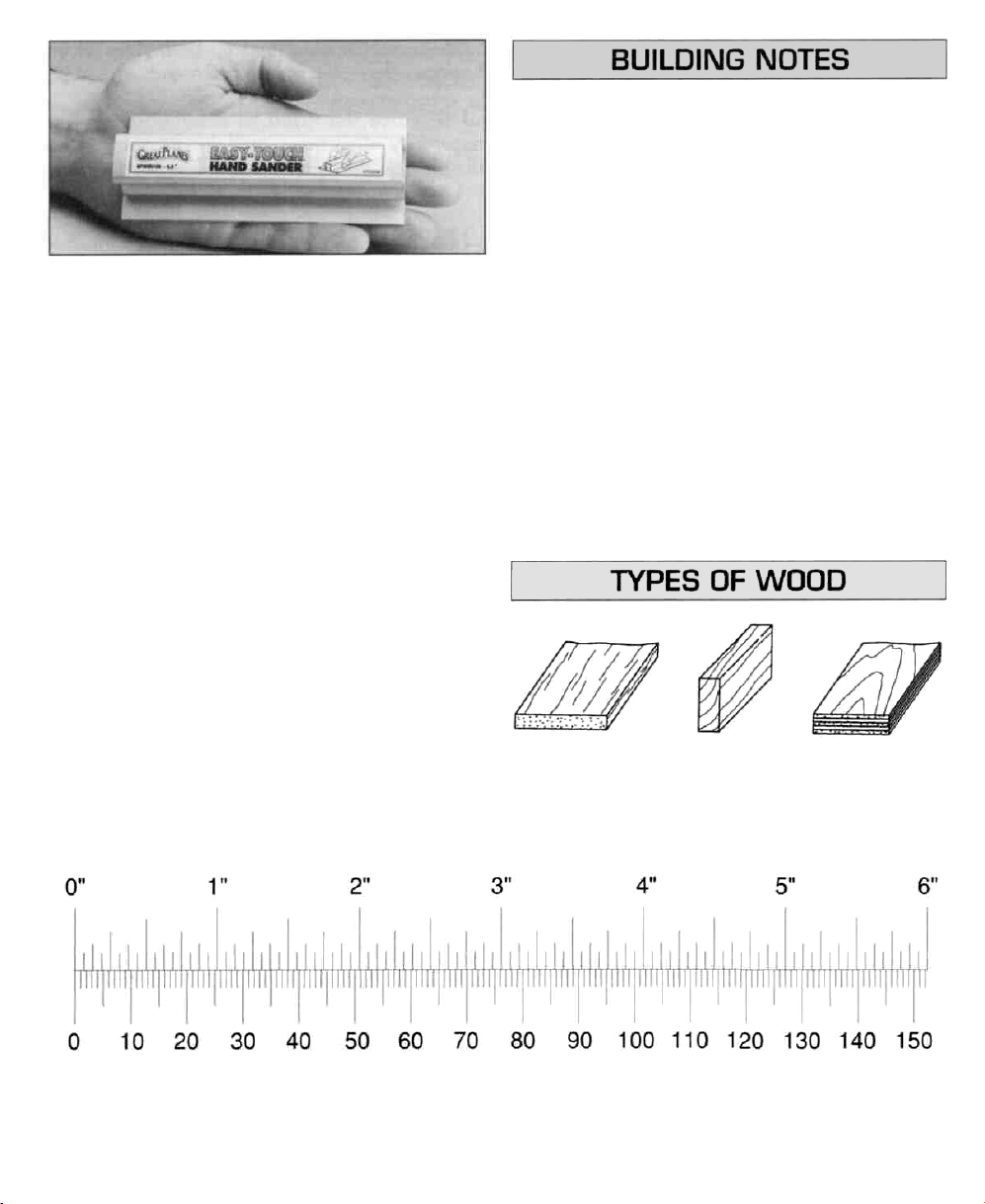
A flat, durable, easy-to-handle sanding tool is a
necessity for building model airplanes. Great Planes
makes a complete range of Easy-Touch" Bar Sanders
and replaceable Easy-Touch adhesive-backed
sandpaper.
• When you see the term "test
instructions, it means you should first position
the part on the assembly without using any
glue. Slightly modify or "custom fit" the part as
necessary for the best fit.
• Whenever just "epoxy" is specified, you may
use either 30-minute epoxy or 6-minute epoxy.
When 30-minute epoxy is specified, it is highly
recommended that you use only 30-minute
epoxy because you will need either the working
time and/or the additional strength.
fit"
in the
For future reference, here's a list of Easy-Touch
Sanders and adhesive-backed sandpaper:
5-1/2" Bar Sander (GPMR6169)
11 "Bar Sander (GPMR6170)
22" Bar Sander (GPMR6172)
12" Roll of adhesive-backed sandpaper,
80-grit (GPMR6180)
150-grit (GPMR6183)
220-grit (GPMR6185)
Assortment pack of 5-1/2" strips (GPMR6189)
Inch Scale
Bar
• Do not throw away any leftover material
after you have completed your Bobcat. Some
small pieces of leftover balsa or plywood are
used during construction.
Balsa Basswood Plywood
until
Metric Scale
5
Page 6
All the parts in the following steps are die-cut 1/8"
plywood unless otherwise noted. After you remove
die-cut parts from their die sheets, remove slivers
and die-cutting irregularities with a bar sander and
80-grit sandpaper.
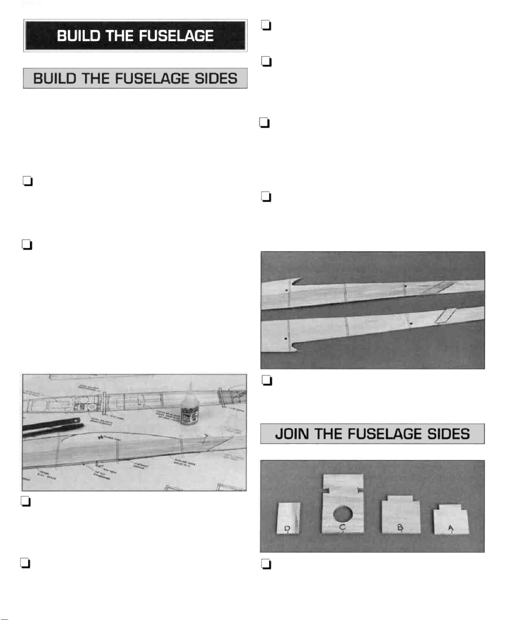
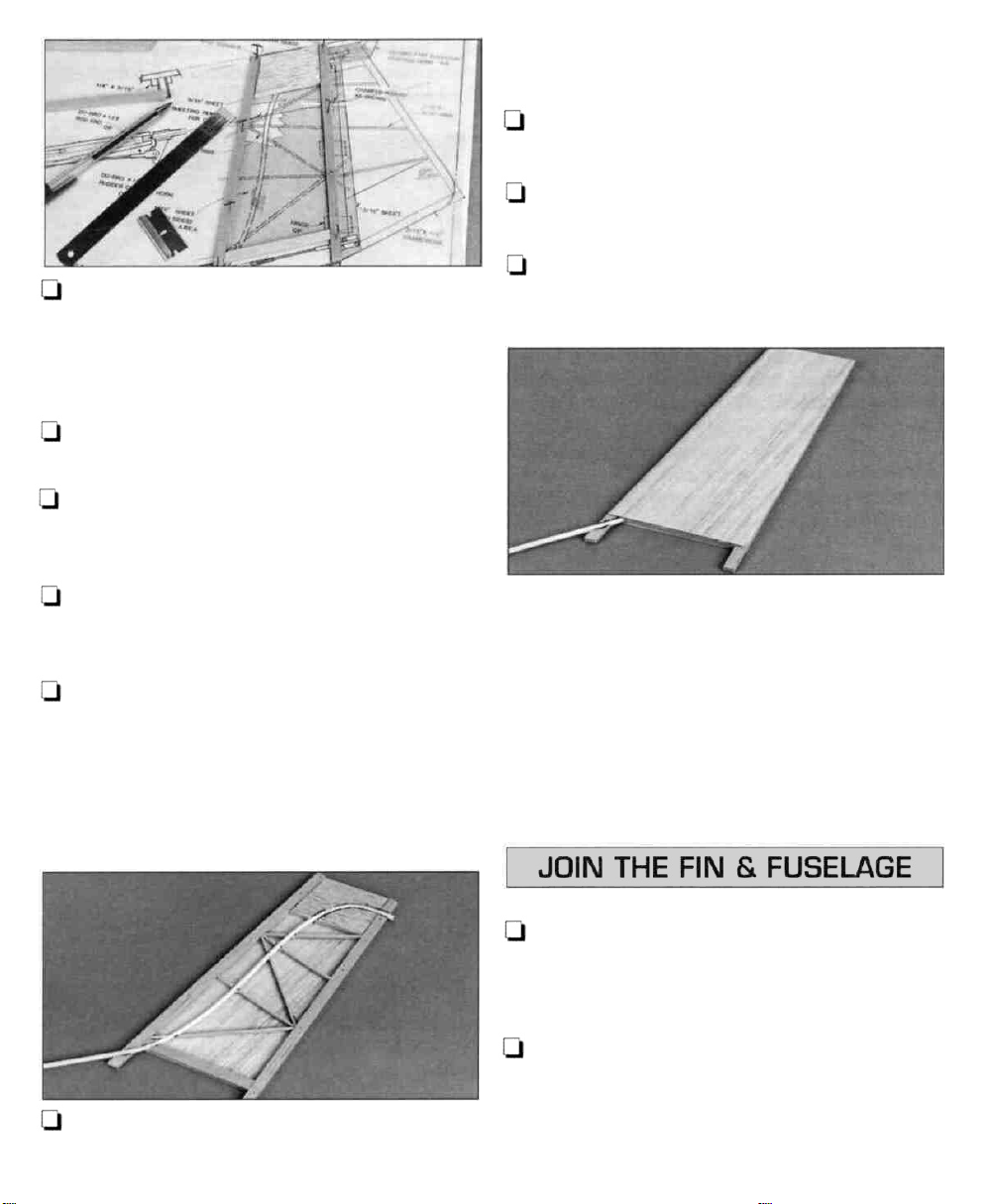
1. Unroll the fuselage plan. Reroll it the opposite
way so it will lie flat. Align the side view of the
fuselage plan over a flat building board into which
you can stick T-pins.
Q 2. Lay a piece of wax paper on the fuselage plan
over the joint between the forward and aft fuselage
sides
so
glue
will
not stick
forward right fuselage side over its location on the
plan. Test fit the aft right fuselage side to it. Use
your bar sander to adjust the forward edge of the aft
fuselage side so it accurately aligns with its location
over the plan. Glue it to the forward fuselage side
with medium CA.
to
the
plan.
Pin
the
Q 5. Sand the glue joint on both sides of the
fuselage sides so it is smooth and even.
U 6. Place the fuselage sides together and
accurately align them. Drill 3/16" holes in the
dimples on the left fuselage side for the wing
hold-down dowels.
U 7. Transfer the lines you marked on the inside of
the right fuselage side to the left fuselage side by
marking them on the top and bottom of the left
fuselage side. Draw the lines with a straightedge
and your ballpoint pen.
Q 8. Use medium CA to glue the left and right
fuselage side joiners to the inside of the left and
right fuselage sides, respectively, so their top edges
are 1/16" below the top edges of the fuselage sides.
U 3. Before you remove the right fuselage side from
the plan, use a straightedge and a ballpoint pen to
accurately mark the location of the three formers
onto the fuselage side.
U 4. Remove the right fuselage side from the plan.
Glue the forward left fuselage side to the aft left
fuselage side the same way.
LJ 9. Sand the bottom edges of the joiners so they
are even with the bottoms of the fuselage sides.
CJ 1. Accurately mark the center of the bottom of the
bulkheads. Label them as shown on the plan and in
the photo.
6
Page 7
D
2.
Optional: Drill a 3/16" hole near the bottom
of bulkheads A and B for an antenna guide tube (not
included). The hole in bulkhead B must be slightly off
center so the guide tube will not interfere with the
tow hook block.
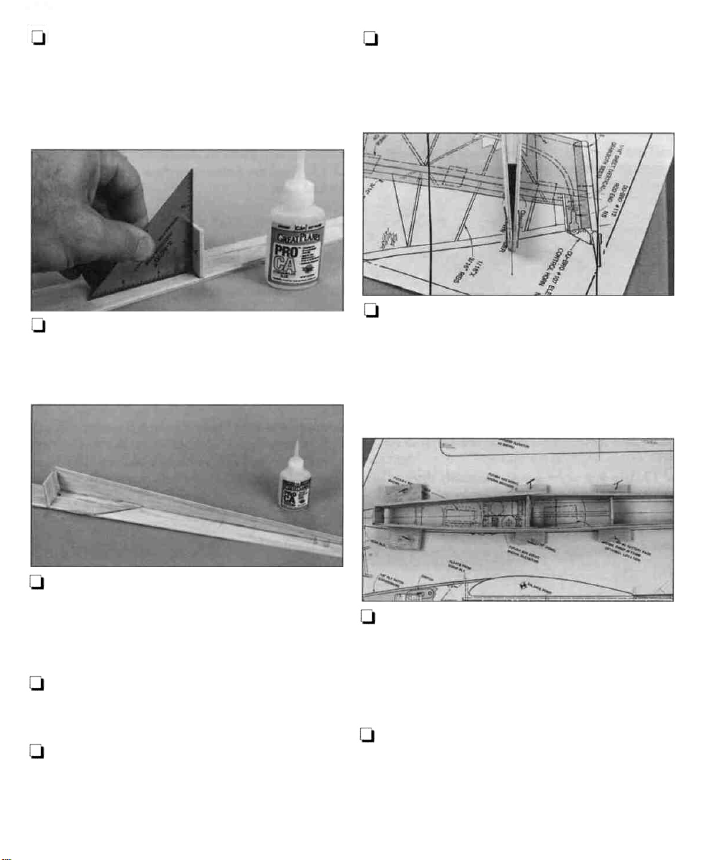
LJ 3. Use medium CA to glue bulkhead A to the
right fuselage side so it is even with the fuse bottom.
Use a small 90 degree triangle to hold the bulkhead
perpendicular to the fuse side while you glue.
Q 7. Use a straightedge and a ballpoint pen
extend the centerline on the top view of the fuselage
plan an additional 9" from the rear of the fuselage
on the plan. Cover the top view of the plan with wax
paper from bulkhead A to bulkhead D.
LJ 8. Position the fuselage on the top view and
accurately align the aft end of the fuselage over the
centerline, then hold it in position with a large T-pin
on both sides. Align the centerline on bulkhead A
with the centerline on the plan. Hold the fuse in
position with a balsa block and T-pins on both sides
of the fuse.
to
Q 4. Remove the die-cut 1/16" balsa
the die sheet and sand off slivers and die-cutting
irregularities. Cut the aft end of the crutch so it
matches the length shown on the plan.
Q 5. Use thin CA to glue the crutch to the right
fuselage side so it is perpendicular and the front of the
crutch overlaps bulkhead A as shown on the plan.
LJ 6. Join the left fuselage side to the right fuselage
side. Accurately align bulkhead A with the lines you
marked on the left fuse side and align the crutch with
the left fuse side. Use medium CA to glue bulkhead
A to the left fuse side.
crutch
from
Q 9. Fit, but do not glue, the rest of the bulkheads
between the fuse sides. Use the "balsa block and
T-pin" technique to hold the fuselage in position so
the centerlines of the formers align with the
centerline on the plan. Hold the fuse sides to
bulkhead D with masking tape.
U 10. Double-check that the formers align with both
the plan and the lines you marked on the inside of
the fuse sides. Also make sure that the bottoms of the
formers align with the bottoms of the fuse sides. Glue
the formers to the fuse sides with thin CA, followed
with medium CA.
7
Page 8
U 11. Remove the fuselage from your building
board. Sand the bottom so the formers and fuselage
sides are even. Sand the top of the fuselage sides
and the crutch so they are even.
Q 12. Glue the cross-grain sheeting cut from a
1/16" x 3" x 24" balsa sheet to the aft fuselage top.
The cross grain sheeting should extend from
bulkhead A aft to the end of the crutch.
U 13. Use a straightedge to accurately draw a line
with a ballpoint pen down the center of the 1/8" x
2" x 23-7/8" cross-grain plywood sheet. Cut the
sheet to a length of 12-3/4".
LJ 15. Sand the bottom ply sheet so it is even with
the fuse sides.
LI 16. Glue the 1/4" x 3/8" x 4-1/4" basswood
tow hook anchor to the inside of the forward fuse
bottom, between bulkheads A and B with medium
CA. Note that the 1 /4" side of the anchor is the side
that contacts the fuse bottom.
Note: Perform step 1 only if your are an experienced
pilot who will be able to take advantage of
a steerable rudder. Ailerons alone will allow
intermediate fliers to turn the Bobcat properly.
Q 14. Use medium CA to glue the 12-3/4"
cross-grain plywood sheet to the bottom of the
fuselage so the aft edge aligns with the middle of
bulkhead B and the centerline on the bottom sheet
aligns with the center marks on the bulkheads.
LJ 1. Make the slot for the rudder pushrod guide
tube in the rear of the left fuselage side at the
location shown in the photo and on the plan. Use a
3/16" brass tube sharpened at one end, a 3/16"
drill or a hobby knife.
Do not use CA Accelerator while you build the fin.
Residual accelerator may cure the CA you use to
glue on the fin sheeting before you have a chance
to position it.
8
Page 9
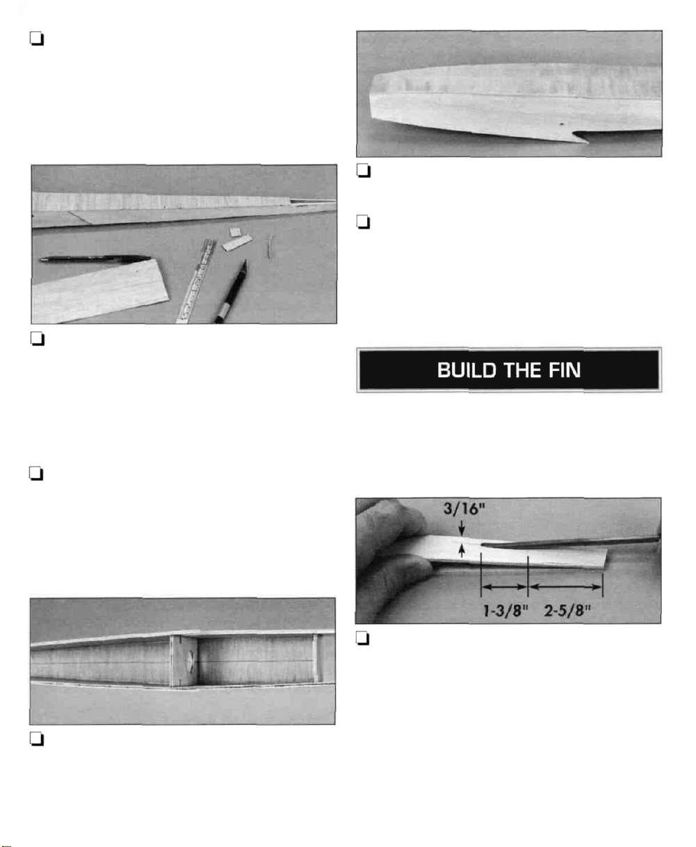
Q 2. Place a sheet of wax paper over the rudder
and fin plan. Build the fin frame from the 3/16" x
1/4" x 24" balsa stick and the 3/16" x 1-3/8" x
24" balsa sheet. Build accurately because the fin
establishes the incidence of the stab.
Q 3. Cut the fin ribs from the 1 /16" x 3/16" x 24"
balsa stick. Glue them in position.
U 4. Remove the fin from your building board and
peel off the wax paper. Carefully sand both sides of
the fin flat.
tip
of the fin
to make sure the grooves are deep enough.
U 8. Glue the tube in place with medium CA. Sheet
the left side of the fin the same way as the right.
Q 9. Sand the tip of the fin so it accurately matches
the plan. Round the leading edge.
U 10. If you will be building a functioning rudder,
mark the location of the hinges on the fin and cut the
hinge slots.
and
in
the cross braces.
Test
fit
the
tube
Q 5. Use a ballpoint pen to mark the left side of the
fin where the elevator pushrod tube (not included,
GPMQ3702) intersects the braces, base and tip.
Q 6. Sheet the right side of the fin with a 1/16" x
3" x 24" balsa sheet. The bottom of the sheet should
align with the bottom of the horizontal 3/16" x 1/4"
"base" portion of the fin. The grain of the sheet
should run parallel to the LE. Use a small piece of
leftover 1/16" balsa sheet for the corner of the fin
the bottom of the
Q 7. Use a MultiPro™ or a hobby knife to cut
grooves for the elevator pushrod guide tube in the
TE.
A nice little piece of workmanship you have there,
isn't it?
at
Q 1. Test fit the fin and the guide tube in the
fuselage. If necessary, trim the aft edge of the 1/16"
balsa crutch and cross-grain sheeting so the TE of
the fin aligns with the end of the fuselage.
U 2. Place a piece of wax paper under the back of
the fuse to protect your workbench. Place weights on
top of the fuselage to keep it from moving around
while you work. Wrap masking tape 1/8" above the
bottom of the fin to keep excess epoxy off the fin.
9
Page 10
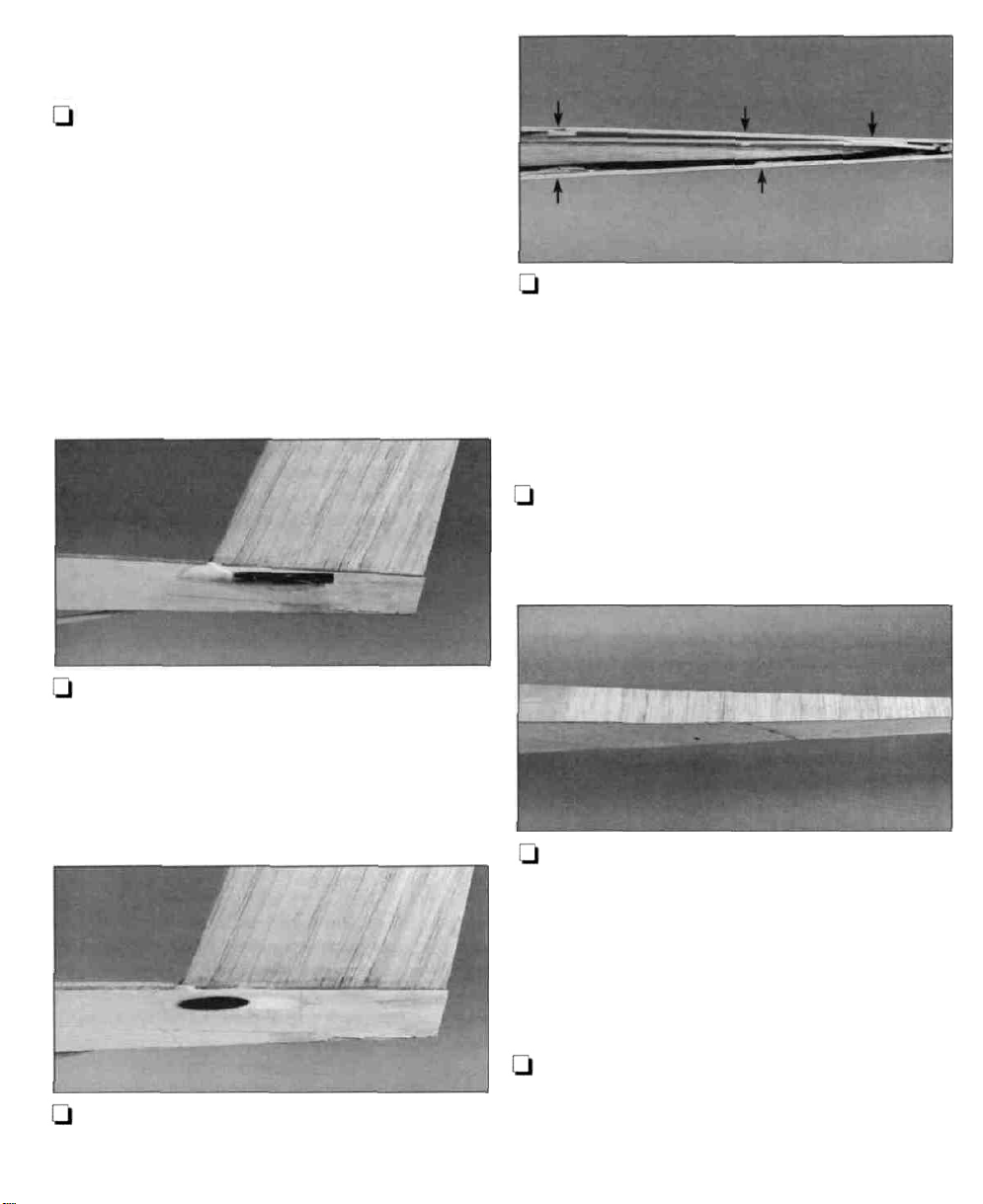
d 3. Apply 30-minute epoxy to the base of the fin,
the top of the fuse sides and all other mating surfaces.
Insert the fin into the fuse. Clamp the fuse sides to the
fin TE with a clothespin. Push a T-pin through the top
sheeting into the LE to hold the front of the fin down.
Immediately proceed to the next step.
Q 4. Make a fillet of epoxy joining the base of the
fin and the fuse. Use a 90 degree triangle to make
sure the fin is perpendicular. Remove the masking
tape before the epoxy cures and do not disturb the
model until the epoxy is fully cured.
Q 4. Glue the front hatch tongue to the bottom
the hatch so half of it protrudes past the front
edge
of the hatch.
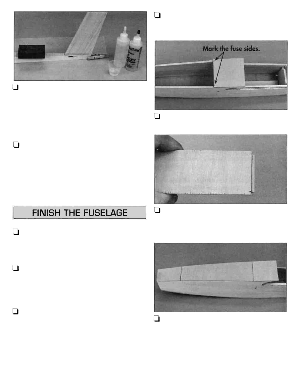
U 5. Use a ballpoint pen to mark the inside edges
of the fuse sides on the aft 2" plywood strip.
of
Q 1. Cut two 2" pieces and one 5-3/4" piece from
the remaining cross-grain 1/8" x 2" plywood strip.
Use medium CA to glue one of the 2" strips to the
front of the fuselage as shown on the plan.
Q 2. Use the 5-3/4" plywood strip (which will
become the top of the hatch) as a spacer to glue the
other 2" plywood strip to the aft portion of the
fuselage cabin. Leave a small gap at both ends of the
hatch to provide clearance for the covering material.
U 3. Use the remaining 1/8" x 2" plywood strip to
make two 3/8" wide hatch tongues. The aft hatch
tongue should be the same width as the inside of the
fuse sides at the back of the hatch. The front hatch
tongue should be the same width as the fuse sides at
the front of the hatch.
LI 6. Position the hatch on the fuselage and transfer
the marks to the hatch so you know where to glue the
aft hatch tongue. Glue the aft hatch tongue so 1 /8" of
the tongue extends past the aft edge of the hatch.
Q 7. Fit the hatch to the fuselage by first inserting
the front hatch tongue under the front fuse top. Next,
bend the hatch so you can slip the aft tongue under
the aft cabin top. Sand all the plywood pieces so
they are even with the fuse sides.
10
Page 11
Skip to
step
11 if you
will
not be
building
the
functional rudder.
Q 8. Cut a 36" outer pushrod guide tube to a length
of 29". Use coarse sandpaper to roughen the
outside so glue will stick. Slide the tube through the
exit slot in the rear of the fuselage until the front of
the tube extends past bulkhead C the same amount
as the elevator guide tube (this should be about
Make sure the rudder guide tube does not interfere
with the fin LE or the elevator guide tube. If it does,
adjust the position of the exit slot until there is
no interference.
2").
LJ 11. Glue the elevator guide tube and the rudder
guide tube (if you have one) to the inside of the
fuselage sides in a few locations with epoxy.
Because of the angle at which the guide tubes enter
the fuselage at the rear, they should naturally contact
the inside of the fuselage sides in a few spots. This is
where you should glue them.
U 12. Sheet the bottom of the fuselage in a cross-grain
fashion with the remainder of the 1/16" x 3" x 24"
balsa sheet you used for the top of the fuselage.
Q 9. Glue the guide tube to the fuselage side in the exit
slot with 30-minute epoxy and microballoons or just
thin CA. If you use thin CA, fill the slot around the guide
tube with lightweight balsa filler such as Hobbylite".
Q 10. Use your bar sander and 80-grit sandpaper to
sand the exit tube and filler flush with the fuselage side.
1-1 13. Cut, but do not glue, a strip of 1/16" x 3"
balsa to fit on the bottom balsa sheeting joining the
aft edge of the bottom ply sheeting as shown on the
plan. Taper the aft edge of the sheet. Glue it
in
position. Use your bar sander and 80-grit
sandpaper to sand the bottom sheeting even with the
fuselage sides and plywood sheeting.
Q 14. Make the tail skid from a piece of leftover
1/8" plywood. You can glue it now to the bottom
sheeting in the location shown on the plan or you
can wait until after you cover the fuselage.
11
Page 12

U 15. Make sure the front of the fuselage sides, top
and bottom are flush with the front bulkhead D.
Securely glue the balsa nose block in position with
medium or thick CA.
U 16. Shape the nose block with a razor plane or a
hobby knife, followed by progressively finer grits of
sandpaper, to match the contour of the fuselage
shown on the plan.
U 17. If you have drilled holes in bulkheads A and B
for the antenna guide tube, install the guide tube. Cut
a hole in the bottom of the fuselage near the aft end
so the guide tube can exit. Glue the tube in position.
Fill the gaps around the tube at the exit and sand it
flush with the bottom sheeting after the filler dries.
Q 2. Use the remainder of the 3/16" x 1/4" x 24"
balsa stick you used to build the fin and an
additional 3/16" x 1/4" x 24" balsa stick, to build
the rudder framework. Cut the pieces to the correct
length. Pin them in their location over the plan
glue them together with medium
IJ 3. Use the remainder of the 3/16" x 1-3/8" x
24" balsa sheet you also used for the tip of the fin to
make the
position with medium CA.
Q 4. Cut the rudder ribs from the remainder of the
1/16" x 3/16" x 24" balsa stick you originally used
for the fin ribs. Glue them in position with medium CA.
U 5. Remove the T-pins. Lift the rudder from the
plan and peel off the wax paper. Lightly sand the
rudder to remove any glue bumps and high spots. If
you use a sanding block, be careful not to snag the
1/16" ribs with the edges of the sandpaper.
Q 6. Round the bottom of the rudder as shown on
the plan. Taper the rudder toward the trailing edge
to a thickness of approximately 3/32" or round the
trailing edge the same as the leading edge of the fin.
base
of the rudder. Glue the base in
CA.
and
Q 1. Position the rudder portion of the plan
your building board. Cover it with wax paper.
over
Perform steps 7, 8 and 9 only if you are going to
build a functional rudder.
U 7. Cut the hinge slots in the rudder in the location
shown on the plan. Shape the leading edge of the
rudder to a "V" as shown on the plan.
12
Page 13

HINGED RUDDER
1/16" X 1/2" BALSA SHEETS
EVEN WITH AFT EDGE OF "V"
ON LEADING EDGE OF RUDDER
Q 8. Cut two 1 /2" x 7" strips from the remainder of
the 1/16" x 3" balsa sheet you used to sheet the fin.
Glue the strips to both sides of the leading edge of
the rudder with medium CA so the front edge of the
1/16" strips are even with the aft edge of the "V as
shown on the plan.
Perform steps 10, 11 and 12 only if you are
building a fixed rudder.
FIXED RUDDER
1/16" X 1/2" BALSA SHEETS
EVEN WITH LEADING EDGE
OF RUDDER
Q 10. Cut two 1/2" x 7" strips from the remainder
of the 1/16" x 3" balsa sheet you used to sheet the
fin. Glue the strips to both sides of the leading edge
of the rudder with medium CA so the front edge
the 1/16" strips are even with the leading edge
of
of
the rudder.
Q
11. Sand the ends of the 1/16" strips so they are
even with the top and bottom of the rudder.
U 12. Use medium CA to glue the rudder to the fin.
Use a straightedge to make sure you glue the rudder
on straight.
Tne optional fin tip filler constructed in the next three
steps enhances your Bobcat's appearance.
Q 9. Mark the location of the hinges on the rudder
where shown on the plan. Cut the hinge slots. Cut
three hinges to the size shown on the plan from the
supplied CA hinge strip. Test fit the rudder to the fin
with the hinges. If necessary, adjust the width or
position of hinge slots that don't align.
Q 13. Cut two 1/16" x 1/16" x 1" strips from a
piece of leftover 1/16" balsa. Glue them to the top
trailing edge of the fin above the rudder with medium
CA. The strips should be inset from the outer skin of
the rudder by 1/16" but must not obstruct the hole in
the pushrod guide tube for the elevator cable.
13
Page 14

Q 3. Use a hobby knife and a straightedge to bevel
one end of the 3/16" x 1-3/8" x 3-3/4" balsa
sheet to make the stab center. Glue it to the stab LE
and TE with medium CA in the location shown
the plan.
Q 4. Cut the stab ribs from a 1 /16" x 3/16" x 24"
balsa strip. Glue them in position with medium CA.
on
LJ 14. Make two fin tip fillers from leftover 1/16"
balsa sheeting. Glue them to the trailing edge of the
fin so there is 1/16" clearance between the fillers
and the top of the rudder (if you have built a
non-functioning rudder, the fillers should extend all
the way to the rudder tip). Make the fillers oversize
so you can sand them to exact shape after you glue
them in position.
U 15. Sand fillers so they are even with the fop of
the fin and the TE of the rudder.
Q 1. Position the stabilizer portion of the plan over
your
building board. Cover it with wax paper.
Q 5. Remove the T-pins. Lift the stab from the plan
and peel off the wax paper. Lightly sand the stab to
remove any glue bumps and high spots. With such a
lightweight structure it is necessary to even only the
high spots, so don't weaken the structure by sanding
too much.
Q 6. Use the remainder of the 3/16" x 1-3/8"
balsa sheet you used for the fin tip and rudder base
to make the
hinges. Cut the hinge slots and bevel the leading
edge to a "V" as shown on the cross section. Taper
the elevator toward the trailing edge to a thickness
of 3/32" or just round-off the trailing edge.
U 7. Test fit the elevator to the stab with four more
hinges cut to the size shown on the plan from the
hinge strip. If necessary, adjust the width
position of the hinge slots so they align.
U 8. Starting with your bar sander, round the
leading edge and tips of the stab as shown on the
plan. Finish by hand-sanding with progressively
finer grits of sandpaper. Blend the ends of the
elevator to the stab tips for a finished appearance.
elevator.
Mark the location of the
and
Refer to fhis photo while you are building the stab.
Q 2. Use the remainder of the 3/16" x 1/4" x 24"
balsa stick you used for the rudder and two
additional 3/16" x 1/4" x 24" balsa sticks to build
the stab framework. Cut the pieces to the correct
length. Pin them in their location over the plan and
glue them together with medium CA.
L-l 9. Separate the elevator from the stab and
remove the hinges from the stab. Mark a vertical
centerline on the both sides of the stab.
14
Page 15
Some modelers prefer to glue the stab to the fin
after they cover them with MonoKote® film. If this
is your preference, perform the following steps but
use T-pins to temporarily hold the stab to the fin
instead of permanently gluing it in position.
Continue building, skipping the rest of the steps
that can't be done without the stab joined to the
fin. Cover the fin, fuse and stab with MonoKote
film after the parts have been final sanded. Leave
the balsa exposed on the center of the bottom of
the stab where it will contact the fin and the
triangle stab reinforcements. Return to this part of
the manual and glue the stab to the fin. Perform
the steps that you skipped.
Q 1. Drill two 3/32" vertical holes through the
centerline on the stab at the locations shown on
the plan.
U 2. Use a straightedge to draw a centerline on top
of the fin. Place the stab on top of the fin as shown
on the plan. Align the centerlines on the stab with
the leading and trailing edges of the fin and align
the holes in the stab with the centerline on the fin.
Q 4. Remove the stab. Drill 3/32" holes in the top
of the fin (or use your sharpened 3/32" brass tube
to make the holes). Cut two 1" pieces from the
3/32" dowel. Test fit the stab to the fin with the
dowels. Remove the stab and the dowels.
Q 5. Temporarily reattach the elevator to the stab
with the hinges.
LJ 6. Spread a film of 30-minute epoxy on top of
the fin and the bottom of the stab and pack the holes
in the fin with epoxy. Glue the stab to the fin with the
dowels using a 90 degree triangle to make sure the
stab is perpendicular to the fin. Hold the stab in
position with small T-pins and wipe away excess
epoxy with a tissue. Do not disturb the model until
the epoxy has fully cured.
LJ 7. Trim the dowels so they are nearly flush with
the top of the stab. Sand them flush with your bar
sander and 220-grit sandpaper.
U 3. Use the holes in the stab as a "template" to
mark the location of the holes on top of the fin with a
3/32" brass tube sharpened at one end, a ballpoint
pen or a pencil or the 3/32" dowel sharpened to a
point at one end.
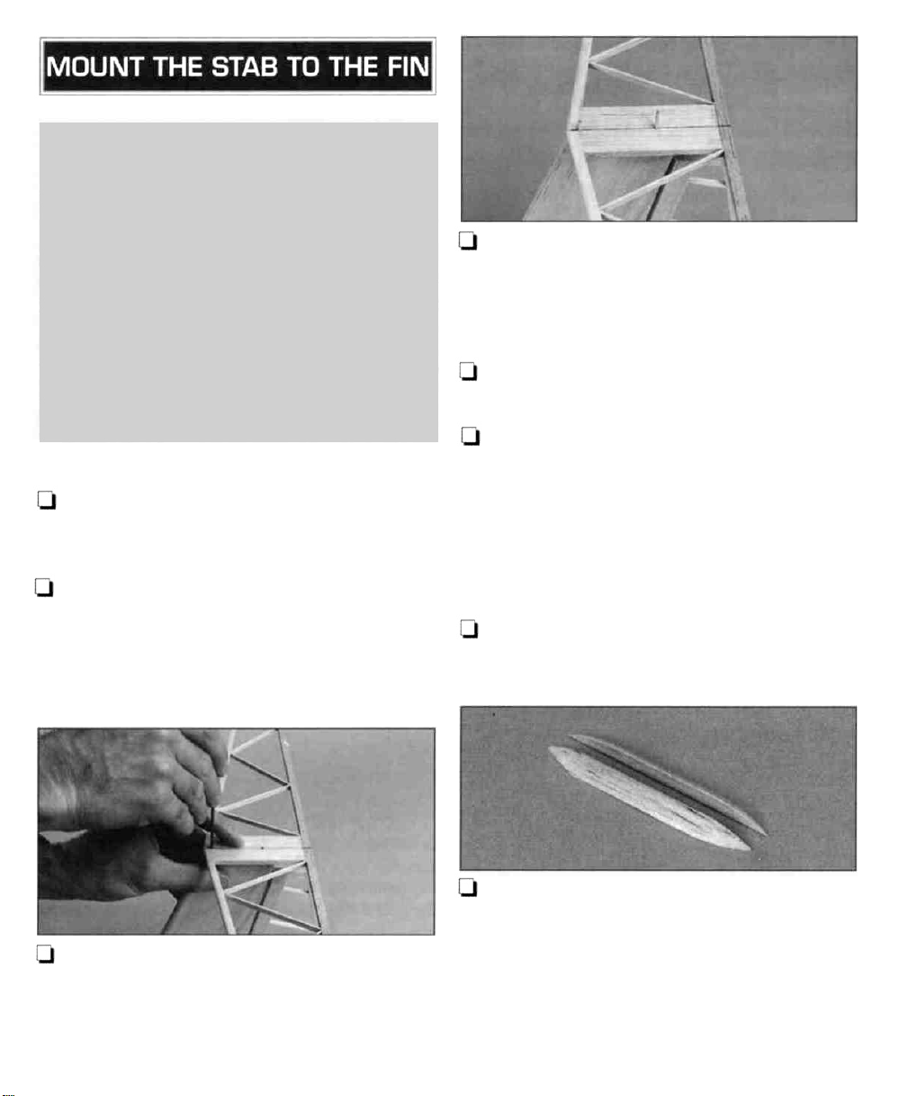
Q 8. From the 1/4" x 12" triangle stick, cut two
3-1/4" pieces to reinforce the glue joint between
the fin and the stab. Bevel the ends of the stab
reinforcements for a finished appearance.
Note: The plan shows a 1/4" x 3/16" stick in this
area, but 1 /4" triangle stock is just as strong and
provides a more finished appearance.
15
Page 16

LJ 9. If you are going cover the model before you
glue the stab to the fin, set the triangle fin
reinforcements aside until you are ready to glue
them in place after you cover the fin and stab.
Otherwise, glue the stab reinforcements to the stab
and fin at this time.
A nice-looking fuselage, isn't it? That T-tail is
interesting and pleasing to look at. Clean up your
workbench, vacuum the floor and get out the
wing
plan.
LJ 1. Carefully remove the 1/16" die-cut balsa
wing ribs from their die sheets. If a rib will not easily
come out of the die sheet, do not force
it. Use a #1 1 blade to cut the wood where
necessary. Sand slivers or die-cutting bumps from
the ribs.
LI
4. Use
a 90-degree square to draw a vertical line
on the ribs of the right side panel at the mark you
made. Starting at the innermost rib #2, make a mark
along the vertical line 1 /8" below the top of the rib.
On the next, make a mark 1 /4" below the top of the
rib. Continue marking along the vertical line on the
rest of the ribs in increments of 1/8" until you reach
the sixth and outermost rib, where the mark should
be approximately 3/8" from the bottom of the rib.
U 5. Mark the ribs of the left side of the panel the
same
way.
U 2. Arrange the plan so the center section is over
your building board. Tape it down.
U 3. Gather all the #2 ribs (there are fourteen of
them). One at a time, position a #2 rib over its
location on the plan and use a ballpoint pen to mark
the rib where the aileron pushrod guide tube crosses
it on the plan.
Q 6. Use a 5/32" brass tube sharpened at one end
or a 5/32" drill to cut (or drill) the holes in the ribs
at the marks you made. The sharpened brass tube
cuts the holes more cleanly. Make a 5/32" hole in
the remaining two #2 ribs in the same location as
the hole in the outermost #2 ribs. These are the root
ribs of the outer wing panels.
Q 7. Cover the center section of the wing plan with
wax paper (you'll be gluing soon!).
16
Page 17
1/8" X 3/8" BASSWOOD SPAR
Q 8. Pin a 1/8" x 3/8" x 30" basswood
spar over its location on the plan. Do not attempt to
insert the T-pins through the spar (basswood can be
pretty hard stuff). Insert them over the spar in a
criss-cross fashion as shown.
bottom
RIB
NO.
1
1/16"
BOTTOM SHEETING
1/4" STRIP CUT FROM
1/16" LEFTOVER BALSA
1/16" VERTICAL GRAIN
SHEAR WEB
AFT
BOTTOM TE
Q 9. Pin one of the 1/16" x 1-3/8" x 30" balsa
trailing edge sheets over its location on the plan.
Q
10. Mark the bottom main spar and the bottom
TE where the three #1 ribs contact them.
Q 11. Make the aft bottom center section sheeting
from the 1/16" x 3" x 24" balsa sheet. Glue it to the
bottom spar and bottom TE sheeting.
Q 12. Cut 1/4" strips from leftover 1/16" balsa
sheet to fit under the outer #1 ribs ahead of the
bottom spar. Place the strips over their location on
the plan but do not glue them to the ribs. These are
just shims to temporarily align the ribs while you
build the wing.
Q 14. Use the same 1/16" x 3" balsa sheet you
used for the aft bottom center section sheeting to
make a vertical grain shear web to fit between the
#1 ribs. The web should be centered on the spar and
extend from the bottom spar to the bottom of the
notches in the ribs.
Q 15. Cut the remaining #1 rib in the middle
the top and bottom spar notches. Discard the
front piece.
Q
16.
Test
fit the aft
section sheeting at the marks you made that indicate
its location. If necessary, trim the front of the rib so it
joins the center web and its notches align with the
other #1 ribs (you will probably have to trim about
1 /32" off the front of the rib).
piece
of
rib
#1
on the center
of
U 13. Glue the outer #1 ribs (with the holes you
made) on top of the 1/16" aft bottom center section
wing sheeting with medium CA. Use a small 90
degree triangle to hold the ribs vertical as you apply
the glue.
17. Glue the center rib #1 in position
medium CA.
17
with
Page 18

LJ 18. Glue all the #2 ribs to the spar and TE with
medium CA. Use a small 90 degree triangle to keep
the ribs vertical as you apply the glue.
Q 19. Read the Tip that follows. Glue the 5/16" x
30" hardwood leading edge dowel to the ribs with
medium CA.
U 22. One at a time, remove the T-pins from the
bottom TE sheeting. Replace them in the rear of the
ribs to hold the aft end of the wing panel to your
building
glue the top TE sheeting in position without
interfering with the T-pins.
Q 23. Test fit and final shape the 1 /4" x 6" tapered
balsa trailing edge stock so it is the same height and
has the same taper angle as the "notched section" of
the #2 ribs and there will be enough room to inset
the 1/8" x 3/16" x 4" basswood stick so it will be
even with the TE.
board.
This
will
allow
you
to
Tip: Spray the
dowel
with CA Accelerator before
you position it on the fronts of the ribs. This
way the CA will be sure to cure immediately,
reducing the time you have to hold the dowel
in position.
Q 20. Test fit the 1/8" x 1/8" x 30" basswood
turbulator spars in the notches of the ribs. Glue
them in place with medium or thin CA.
Q 21. Glue a die-cut 1/16" gusset to the bottom
sheeting and outer rib #2 at both ends of the wing
panel.
Q 24. Use medium CA to glue the trailing edge
stock to the end of the #1 ribs and the bottom TE
sheeting. Cut a notch in the bottom TE sheeting for
the 1/8" x 3/16"x 4" basswood stick. Glue it
position as shown in the photo.
Note: The 1/8" side of the stick should contact the
plan while the 3/16" sides should be vertical.
U 25. Use the 1/16" x 3" balsa sheet to make six
vertical grain shear webs to fit between the #2 ribs of
the left side of the panel. Glue all the shear webs -
except the shear web between the outer set of #2
18
in
Page 19

ribs - to the bottom spar and ribs with medium CA.
Set the outermost shear web for the last set of #2 ribs
aside for now. Remove the crossed T-pins that are in
the way, but reinstall them through the shear web after
you glue it in place.
Q 26. Cut and glue five shear webs in the right side
of the center wing panel the same way.
Q 27. Position the 1/16" x 1-3/8" x 30" balsa
upper TE sheet on the ribs. Mark the location of the
1/8" x 3/16" basswood stick and cut a notch in the
TE sheet. Glue the TE sheet in position with medium
or thick CA.
Q 28. Test fit the 1 /8" x 3/8" x 3" basswood top
spar in the notches of the ribs. If necessary, adjust
the notches and the tops of the shear webs so the
spar is fully seated into the ribs. Glue the spar in
place with medium or thick CA.
Q 29. Use the remainder of the 1/16" x 3" balsa
sheet to cover the top center section of the wing
between the top spar and the top TE.
LJ 31. Sand the ends of the spars and TE's and LE
so they are flush with the end ribs.
BUILD THE AILERON SERVO
COMPARTMENT HATCH
Q
1.
From
the
1/16" x 3-7/8" x 5-7/8"
sheet, cut and glue a 1 /2" wide strip to fit between
the #1 ribs against the LE. The grain should run
lengthwise.
plywood
Q 30. Remove the T-pins. Lift the panel from your
building board and peel the wax paper off the wing.
The 1/16" shims you placed under the front of the
#1 ribs should fall off.
Q 2. Cut a 1/4" x 1/4" hatch tongue from the
same 1/16" plywood sheet. Glue it to the top of the
bottom spar as shown in the Bottom View Of Servo
Tray
sketch
on the
plan.
Q 3. Cut the hatch from the 1/16" plywood sheet.
There should be approximately a 1/8" gap between
the sides of the hatch and the #1 ribs. You can see
the hatch in the following photo.
19
Page 20

t-1 4. Cut two more 1 /4" x 1 /4" tabs and one 1 /4
x 2" strip to secure the hatch. Glue the 2" strip to the
top (inside) of the hatch. Glue the 1/4" tabs to the
2"
strip.
U 5. Test fit the hatch over the aileron servo
compartment. The tabs on the hatch fit on top of the
bottom spar and the tab on the spar supports the
back of the hatch.
Q 8. Cut the 2" basswood grooved slider block into
two 13/16" long pieces.
Q 9. Make the servo tray from the remaining
1/16" plywood sheet. For now, cut only the outside
edges. Do not cut to fit your servo until the next step.
Start by making the tray slightly too long and slightly
too wide so you can little by little "fine tune" it for the
best fit by sanding the edges. Test fit the servo tray
between the #1 ribs with the slider blocks but do not
glue any of the parts at this time. With the blocks on
either side of the servo tray, the assembly should fit
tightly between the ribs.
Q 6. Hold the hatch in position and drill a 1/16"
hole through the hatch and the 1/16" x 1/2"
plywood hatch retainer (named "cleat" on the plan).
Remove the hatch and enlarge the hole in the hatch
only with a 3/32" drill bit. Temporarily secure the
hatch to the wing with a #2 x 3/8" screw (not
included).
Q 7. Glue two strips cut from 1/16" balsa to the
bottom of both #1 ribs. The strips should align
with the sides of the hatch with an approximately
1/32"gap.
U 10. Remove the servo tray and cut out the middle
to fit your servo. Make sure that the slider blocks will
not interfere with the mount portion of your servo
and the rubber grommets. Mount your servo to the
tray and reposition the assembly in the wing without
using any glue. The exact position of the servo will
be determined when you connect the servo the
aileron control cables.
There, the center section is ready to join to the outer
panels. Oops, we'd better build the outer panels then!
20
Page 21

Build the right wing panel first so your progress
matches the photos.
0 1. Arrange the wing plan so the right wing panel
is over your building board.
U LJ 2. Mark ribs #3, 4, 5 and 6 where the aileron
pushrod
guide
tube
crosses
them. Cut
or
drill
a
5/32" hole 3/8" above the mark on the ribs.
Q Q 3. Cover the plan with wax paper. Pin a
1 /8" x 3/8" x 24" balsa bottom outer spar over its
location on the plan. Since the spar is balsa, you can
stick T-pins through it.
Q Q 4. Cut the wing tip dihedral gauge template
(located on the back cover) along the outer dotted
line. Use rubber cement or spray adhesive to glue
the template to a piece of balsa, thin cardboard (the
kind from cereal boxes) or plywood. Accurately cut
the gauge to the solid outline of the template. You
can see the gauge in the photo at the next step.
TRIM 1/16" FROM THE TOP OF RIBS
6 AND 7 BEHIND THE SPAR
1/16"
REMOVE
Q Q 6. Use a #11 blade to trim 1/16" off the top
of ribs #6 & #7 behind the spar.
LJ LJ 5. Use the wing tip dihedral gauge to
accurately bevel the end of a 3/16" x 5/8" x 24"
balsa aft spar. Pin the spar to your building board
over its location on the plan so the root end aligns
with the plan.
Note: For the best fit between the aft spar and root
rib #2, bevel the spar as seen from the top view to
account for the forward sweep of the trailing edge.
LJ U 7. Test fit and use medium CA to glue ribs #3
through #10 to the bottom spar and the aft spar. Use
a small 90 degree triangle to hold the ribs
perpendicular as you glue them.
LJ U 8. Position root rib #2 over its location on the
plan. Use the dihedral gauge to hold it at the correct
angle and glue it to the bottom spar and the aft spar
with medium CA.
21
Page 22

Q Q 9. Glue the 5/16" x 24" hardwood dowel
leading edge to the ribs. Use the dihedral gauge to
make sure rib #2 it is at the correct angle when you
glue the dowel to it.
Q Q 10. Glue the 1/8" x 1/8" x 24" outer
turbulator spars in the notches of the ribs. Use the
dihedral gauge to make sure rib #2 it is at the
correct angle when you glue the spars to it.
Q Q 11. Make six shear webs from the 1 /16" x 3"
x 24" balsa sheet to fit between the sets of ribs from
#2 out to #7. Cut or drill a 5/32" hole 7/16" from
the bottom of the web where the aileron cable guide
tube passes through.
LJ LJ 15. Use your bar sander to angle the end of
the 5/8" x 1 -3/4" x 24" balsa trailing edge stock
so it fits against rib #2 when placed against the aft
spar. When you have achieved the correct angle on
the end of the trailing edge stock, cut it where shown
on the plan. Glue it to the aft spar and #2 rib. The
approximately 18" of remaining trailing edge stock
will be the aileron.
Q Q
12. Do not glue the shear web between ribs
#2 and
between the ribs with medium CA.
Q Q 13. Test fit the 1/8" x 3/8" x 24" balsa top
outer spar in the notches of the ribs. If necessary
adjust the notches and the tops of the shear webs so
the spar is fully seated into the ribs. Glue the spar in
place with medium or thick CA. Use the dihedral
gauge to hold rib #2 at the correct angle when you
are gluing it to the spar.
Q Q 14. Use medium CA to glue three 1/16"
die-cut balsa gussets to the ribs and aft spar where
shown on the plan.
#3, but glue the rest of the shear webs
O Q 16. From the 1/16" x 3" balsa sheet you used
for the shear webs, cut and test fit the sheeting for
the aileron pushrod guide tube exit that fits on top of
ribs #6 and #7. It is okay if the sheeting extends past
the ribs by approximately 3/32" or so. Glue the
sheet in position.
U U 17. Remove the T-pins from the wing panel.
Lift it off your building board and peel the wax
paper off the panel. Look for glue joints that don't
look strong and reinforce them with medium CA.
Pay special attention to the glue joints between the
shear webs and the spars.
22
Page 23

Q Q 1. Use a razor saw to trim the spars and
leading edge dowel so the ends are nearly flush
with rib #2 at the root of the panel and rib #10 at
the tip of the panel. Sand the ends of the spars and
leading edge dowel flush with the root and tip ribs.
Q Q 2. Sand the end of the 5/8" x 1-3/4" x
approximately 18" balsa aileron so it accurately
matches the end of the trailing edge stock you glued
to the wing.
U LJ 3. Place a piece of leftover 1/16" balsa
between the end of the aileron and the trailing edge
stock to act as a spacer. Cut and sand the tip end of
the aileron so it is flush with tip rib #10.
U U 5. Use a hobby carving knife or a razor plane
to roughly carve the tip to the approximate shape.
Final shape the tip with progressively finer grits of
sandpaper to blend it to the wing and the shape
shown on the plan. When you get to the final stages
of shaping the tip, place the aileron on the wing
help guide you in shaping the aft end of the wing tip.
USE THE DIMENSIONS SHOWN BELOW
TO BEVEL THE AILERON
1/8"
9/32"
U U 6. Mark the locations of the hinge slots on the
aileron and the aft trailing edge of the wing. Cut the
hinge slots. Make sure the height of the hinge slots on
the aft TE and the aileron are the same so the aileron
will be centered when you join it to the wing with the
hinges. Bevel the leading edge of the aileron as
shown
in
the
sketch.
Test
fit
the
aileron to
the
wing
with the hinges.
Hey, you've
completed the first wing panel already!
to
Q Q 4. Cut the 7/8" x 1 -3/8" x 12" tapered wing
tip stock into two 6" pieces. Use medium CA to glue
one of the tips to the panel joining them together while
they are both laying flat (so the tip curves down) on
your building table covered with wax paper.
Q 7. Arrange the plan so the left wing panel is over
your building board. Return to step 2 at Build The
Outer Wing Panels on page 21 and build the left
wing panel. Don't forget to switch to the left wing
panel so you don't build two rights!
23
Page 24

U 1. Sand all three wing panels with fine-grit
sandpaper to remove glue bumps. Blend all the ribs
to the spars, LE and TE. Smooth all surfaces.
U 2. Use a small 90 degree triangle or square to
draw a 1/8" wide slot centered between the spars
on the #2 ribs on both outer wing panels.
U
6.
Test
join the
wing
panels
with
the
dihedral
braces and adjust the slots in the ribs or the length of
the braces so the spars and LE's align and the wing
panels fit together without gaps.
First join the right outer panel to the center panel so
your progress matches the photos.
U 3. Use a sharp #1 1 blade to cut the #2 ribs
along the lines and remove the balsa for the
dihedral brace.
U 4. Mark and cut the slots on the #2 ribs at both
ends of the center wing panel the same way.
Q 5. Remove the die-cut 1/8" plywood dihedral
braces from their die sheets and remove slivers or
die-cutting irregularities with your bar sander.
Position the dihedral braces over the drawing on the
plan and mark the "root" and "tip" ends of the
dihedral braces as shown.
Refer to this photo for joining the wing panels.
U U 1. With the outer panel temporarily joined to
the inner panel, raise the outer panel with a balsa
stick, a stack of balsa sheets or something similar, so
the tip at the last rib is 3/4" above your building
table. Temporarily clamp the panels together with Cclamps, spring clips or clothespins so you will know
where to put them when you are actually gluing.
Note: If your aileron servo is mounted in the wing at
this time, make sure the cord and connector are not
sticking out of the bottom. The center section must
rest flat on your table while you join the outer panel.
24
Page 25

U LJ 2. Remove the clamps and separate the panels.
Lay a piece of wax paper on your building table. Mix
a batch of 30-minute epoxy. Coat the joining surfaces
with 30-minute epoxy. Join the inner wing panels with
the dihedral brace. Refrain from using excess epoxy
so the shear webs will fit later. Place the wing on your
building table. Immediately proceed to the next step.
o o 3. Place a weight on the center section to hold it
down. Prop up the outer panel so the tip is 3/4"
above your table. Clamp the wing halves together
the same as you did in the first step.
Q Q 4. Wipe
not disturb the wing until the
Q 5. Return to step 1 and join the left panel to the
center section the same way.
away
excess
epoxy before
epoxy
is fully cured.
it
cures.
Do
U 3. Make sure the holes in the joining #2 ribs of
both wing panels align so you can route the outer
aileron cable guide tube. If the holes do not align,
open them up with a hobby knife.
Note: These instructions are written for connecting
the ailerons with Great Planes* Flexible Cable
Pushrods, though Sullivan
Gold-N-Push Rods are shown on the plan. If you
decide to use the Sullivan Gold-N-Rods, the
instructions are the same for installing the guide
tubes, but connect the clevises and ball links as
shown on the plan.
U LJ 1. Roughen the outside of a Great Planes 36"
Flexible Cable Pushrod guide tube (not included,
GPMQ3702) with coarse sandpaper so the glue will
stick. Route the guide tube through the holes in the
ribs of the right wing panel.
U U 2. Use a #11 blade to cut an approximately
1/2" diameter circular notch in rib #1 where the
guide
tube
passes.
connector to clear the rib without interfering. See the
photo at step 5.
This
will
allow
the
solder
U 1. Use epoxy to glue the four shear webs you cut
earlier to the plywood dihedral braces and spars on
both sides of the joining wing panels. It does not
matter whether you glue the shear webs to the front
or back of the shear webs, but do it the same way
on all four webs for symmetry.
Q 2. Sand-off glue bumps and blend the spars and
LE's and TE's of the joining wing panels.
1-11- 3. Cut a 1/2"
between ribs #6 and #7 where the guide tube
pass through. Be careful not to make the slot too far
aft or the clevis will interfere with the guide tube and
limit aileron throw. The aft end of the slot should be
approximately 1-1/4" from the aft edge of the aft
spar. Route the guide tube through the slot and
the tube so it protrudes from the sheeting (on top
the wing) about 3/8".
long
slot
in
the
sheeting
25
will
cut
of
Page 26

Q Q 4. Glue a 1/16" balsa strip to the inside of
the sheeting on both sides of the slot to keep the
sheeting from splitting.
Q Q 5. Cut the "servo end" of the tube about 3/4"
from rib#1.
Q Q 6. Glue the guide tube in the slot with
microballoons and epoxy. Glue the tube to the ribs
with medium CA.
Q Q 7. After the microballoons and epoxy filler
has fully cured, use your bar sander and 220-grit
sandpaper to sand the guide tube and the filler flush
with the sheeting. See the photo at step 13.
Q Q 10. Cut the threads off a Great Planes 2-56
(1/16") Threaded Coupler (included with the Great
Planes Flexible Cable Pushrod set) so that 5/16" to
3/8" of the threaded portion remains. Silver solder
the threaded coupler to one end of the aileron cable.
Thread the coupler all the way into the dual end ball
link (included with this kit).
Q Q 11. Route the cable through the guide tube.
Align the ball link socket with the ball link on the
servo but do not snap it on.
Q Q 12. Connect a small control horn (included
with this kit) to a Great Planes 2-56 Solder Clevis
(not included, GPMQ3810). Place the control horn
on the aileron as shown on the plan next to the cable
protruding from the wing.
Note: The control horn should be 1/8" aft of the
aileron pivot point (as shown on the plan) for aileron
differential.
LJ U 8. Remove the aileron servo. Temporarily
install a Great Planes 1/16" Ball Link (not included,
GPMQ3842) onto the servo arm or wheel of your
servo. Reinstall the servo - the sliders should not yet
be glued in place so you can determine the location
of the servo after the exact location of the cable and
ball link socket have been set.
Q Q 9. Reinstall the aileron servo with the ball link
on the servo arm.
Q Q 1 3. With the aileron neutral, mark the cable
where to cut it so you leave enough extra to securely
solder it into the clevis. Remove the clevis from the
control horn. Cut the cable at the mark you made.
26
Page 27

Q Q 14. Silver solder the clevis to the cable. If you
find it difficult to cut the cable with wire cutters, use a
MultiPro with a cut-off wheel or tin the cable in the
area where it is to be cut with wire cutters.
LJ U 15. Place the control horn on the aileron. Drill
1/16" holes in the aileron for the horn mounting
screws. Remove the aileron and use a pin to poke
holes in the aileron where the control horn will be
mounted. Saturate the area and the holes for the
horn mounting screws with thin CA. Sand the area
smooth.
Q 1. Connect the aileron servo to your receiver and
turn on your radio. Center the aileron servo with
your transmitter and make sure both ailerons are
neutral. You can still do this without snapping the
ball
socket
onto
the
ball
by
just
fitting
the
ball
socket
over the ball, but not snapping it on. It is easiest to
center the aileron servo and ailerons now while the
ball linkage is easily accessible rather than at the
flying field when you will have disconnect the ball
link and remove the servo to make an adjustment.
LJ 2. Connect the ball link to the servo arm or wheel
on your aileron servo with the small nut included with
the ball link. Use thread locking compound or epoxy to
make sure the nut is secure.
U Q 16. Mount the control horn to the aileron with
two #2 x 1/2" screws. Fit the aileron to the wing
with the hinges and connect the clevis to the control
horn.
Q Q 17. Place the ball socket over the ball link but
do not snap it on. Adjust the ball socket on the
threaded coupler so the aileron is neutral.
U 18. Return to step 1 and connect the other aileron
the same way. Do not snap the ball socket onto the
ball link until instructed to do so.
U 3. Mix a batch of 30-minute epoxy and glue the
sliders to the #1 ribs. Adjust the sliders so you can
connect the ball socket to the ball on the servo without
bending the aileron cable out of its way. Snap the ball
socket onto the ball. Do not disturb the assembly until
the epoxy is fully cured.
U 4. If you have to make any adjustments to the
aileron servo or connection, make them now before
you sheet the rest of the center section. You can
easily remove the servo from the compartment after
you sheet the center section by sliding the servo tray
out, but it is easier to access the ball and socket now.
Q 5. Use the remainder of the 1/16" sheeting to
sheet the top center section of the wing forward
the main spar.
27
of
Page 28

Back to
time for covering!
Q 1. Cut two 1 /4" x 4" strips from leftover 1 /8"
plywood. Glue them together with medium CA to
make the servo
U 2. From the strips you glued together, cut two
servo rails that will fit between the fuselage sides in
the servo compartment.
0 3. Position your servo(s) on the rails in the fuselage
as shown on the plan. Raise or lower the rails so the
servo arms (or wheels) will align with the pushrods but
make sure the servos will not interfere with the
forward wing dowel. There is enough room for
standard size servos but most advanced fliers will use
mini or micro servos for the least amount of weight.
the fuselage for a little while. It will soon be
rails.
1— 7. Use silver solder to solder a Great Planes
Standard Solder Clevis (not included with this kit,
GPMQ3810) onto the elevator cable (included with
the Great Planes Flexible Cable Pushrod set
previously recommended). Connect the clevis to the
second or third hole of a small nylon control horn
included with this kit.
Q 8. Route the cable through the guide tube and
position the control horn on the elevator as shown
on the plan.
U 9. Use the control horns as a template to drill two
1/16" holes to mount the control horns to the rudder
and elevator with 2-56 x 1 /2" screws in the location
shown on the plan. Connect the rudder pushrod and
elevator cable to the control horns.
LJ 4. Make sure there is enough space between the
rails so you can remove the servos. Glue the rails to
the fuselage sides with medium or thin CA.
Q 5. Mount the servos to the rails with the
screws, grommets and brass inserts included with
your radio system.
Q 6. Cut the elevator and rudder (if you have a
moveable rudder) guide tubes so they extend
approximately 1 /4" forward of bulkhead C.
Q 10. At the servo end, cut the elevator cable and the
rudder pushrod to the correct length. Connect them to
the servos with your favorite type of connector. On our
prototype we used Great Planes Screw-Lock" Pushrod
Connectors (not included, GPMQ3870).
28
Page 29

U 11. Glue the outer pushrod guide tubes to the
bulkheads with thick or medium CA.
Q 12. Wrap your receiver and battery pack in
foam rubber. Mount them in the fuselage where
shown on the plan. Mount the on/off switch in a
location that will not interfere with the pushrods or
the radio system.
We recommend you cover your Bobcat with Top Flite
MonoKote iron-on model covering film. If this is one
of the first times you have covered a model, refrain
from attempting a complicated trim scheme. Add
stripes, graphics and various designs to your Bobcat
cut from different colors of MonoKote film. Iron them
directly over the base color. Try only a single color
base (usually a lighter color such as white or yellow)
with perhaps a single stripe, your AMA number or
even some stick-on graphics. A simple trim scheme
will get you in the air faster and look much better
than an ambitious a trim scheme that makes your
model too difficult to cover.
Q 1. Inspect the wing, fuselage and tail surfaces for
glue joints that don't look strong. Reinforce them with
thin or medium CA. Make sure the fuselage bottom
is securely glued to the fuselage sides in the area of
the tow hook anchor.
Q 2. Temporarily fit the 3/16"
through
the fuselage. If necessary, adjust the shape of the
fuselage sides and the aft plywood fuselage
where they fit over the
U 3. Remove pushrods, wing dowels, control horns
and any other hardware that may interfere with
covering.
Q 4. Fill dents, scratches and glue joints on the
surface of the model that may show through the
covering with HobbyLite filler. Sand the fuselage so it
is smooth and even.
the
holes
in
the
fuselage.
wing.
wing dowels
Test
fit the
wing
on
top
Here is a "rule of thumb" to keep in mind before you
begin: Where possible, apply the covering so all
seams face downward or rearward. You can do
this by covering the bottom (of the wing, fuse, stab,
etc.) first.
Never cut the covering after you iron it to the
wood except near the tips. Modelers who do
this may weaken the structure which could
cause it to fail during flight.
Tail Surfaces:
1. Stabilizer bottom right and left half
2. Stabilizer top
3. Fin right, then left side
4. Rudder
5. Elevator
29
Page 30

Fuselage:
1. Bottom*
2. One side, then the other
3. Top forward, then aft of the hatch
4. Top aft
of wing
5. Hatch
* Many modelers cover the forward bottom section of
the fuselage with two layers of covering or glass cloth
and paint the forward bottom section for better
protection during landings.
Wings:
1. Center panel bottom, then top
2. Outer panel bottoms, then tops
3. Ailerons
4. Hatch
If you decided to cover your Bobcat before you
glue the stab to the fin, return to page 15 and
follow the instructions to glue the stab.
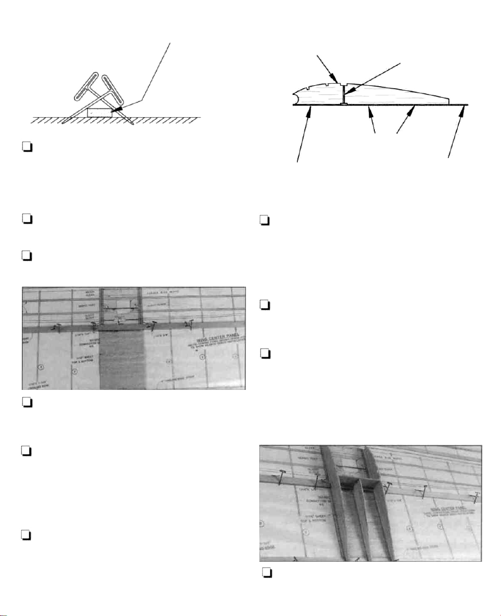
U 2. Lay the center section of the wing on your
building table. Place weights on top of it to hold it
down. Twist the trailing edge upward while you heat
the covering until the wrinkles disappear. Let the
covering cool. Measure the distance between the
trailing edge of the wing at the tip and your building
table. It should be 1/4". You may also have to heat
the bottom of the outer wing panel.
U 3. Add washout to the left outer panel the same
way. Make sure the center section of the wing is flat
and warp free as described in step 1.
Q 1. Due to the lightweight structure of the Bobcat
and the shrinkage of the covering, the wing and stab
can warp or twist. Correct the twists by carefully
twisting the part in the opposite direction. Heat the
covering with your iron or heat gun until the part is
flat and free of warps.
Add "washout" to the wing tips. Washout is where
the trailing edge of the wing at the tip is twisted
upward. This gives the wing tip a lower angle of
attack than the rest of the wing, which will reduce
the tendency for the wing to "tip stall."
Use the instructions below to hinge the ailerons,
elevator and rudder (if you have built a steerable
rudder). Hinge the elevator first because it's
the easiest.
CUT THE COVERING
AWAY
FROM THE SLOT
U 1. Use your hobby knife and a sharp #11 blade to
remove a small strip of covering from the hinge slots.
30
Page 31

TEMPORARY PIN
TO KEEP HINGE
CENTERED
CUT
CUT
RUBBER
BAND
T-PIN
LJ 2. Join the elevator to the stab with the hinges. If
the hinges will not stay centered, stick a pin through
the center of the hinge. Remove the pins after the
hinges are glued in place.
Q 3. There should be a small gap between the
control surfaces (just enough to see light). A small
gap is desirable so you do not inadvertently glue the
parts together.
Q 4. Carefully apply 4 drops of thin CA to both
sides of the hinges. Keep a cloth handy to wipe
away excess CA. If you spill a few drops of CA
on the covering, you can use CA Debonder
(GPMR6039) to remove it or carefully peel it off with
a hobby knife after it fully cures.
Do not use accelerator on any of the hinges. Do not
glue the hinges with anything other than thin CA
and do not attempt to glue one half of the hinge at
a time with medium or thick CA. They will not be
secure and the controls could separate while the
model is flying.
STRAIN RELIEF
INSIDE FUSELAGE
ANTENNA HOLDER
AT
THE
TOP
OF
VERTICAL STABILIZER
THE
Q 2. Route the receiver antenna through the guide
tube (if you installed one) or make a strain relief and
an antenna hook from a cut-off servo arm as shown
in the sketch.
U 3. Cut a hole in the covering over the wing dowel
holes in the fuselage. Install the dowels and glue
them in position with medium CA.
Q 4. Apply 1/16" thick Great Planes Single-Sided
Foam Tape (GPMQ4422) to the wing saddle of
the fuselage.
Q 5. Drill a #36 (or 7/64") hole through the
fuselage bottom and the tow hook anchor. From the
top, enlarge the hole
anchor only with an
1/4"
deep in the tow hook
11/64"
(or
5/32")
drill
to
accept the 6-32 blind nut for the tow hook.
TOW HOOK ANCHOR
6-32 BLIND NUT
Q 5. Let the CA fully cure. Carefully Rex the elevator
several times to check the movement.
Q 6. Hinge the rest of the controls the same way.
Q 1. Reinstall the pushrods and connect
the servo control horns the same way you did
during construction.
FLAT WASHER
6-32
NUT
NO. 6 TOW HOOK
Q 6. Install the tow hook as shown in the sketch and
secure the blind nut and the hex nut with thread lock.
31
Page 32

This section is important and must NOT be omitted.
A model that is not properly balanced will be
unstable and possibly unflyable.
Q
1.
Accurately mark the balance point on the
bottom of the wing near both sides of the fuselage
with tape or a felt-tip pen. The balance point is
shown on the plan and is 3" (77mm) aft of the
leading edge.
LJ 2. Place the wing on the fuselage. Hold it in place
with two or four #64 rubber bands. When it is time to
fly your Bobcat, you should secure the wing with at
least eight rubber bands crossing the last two.
3"
U 2. Measure the throws at the widest part of the
trailing edge of the rudder and elevator. After a few
flights you may change the throws to suit your flight
style or the weather conditions.
We recommend the following control surface
throws:
Ailerons: 1 /2" up and 1 /4" down
Elevator: 1 /4" up and down
Rudder: 3/4" right and left
Q 3. After you set the control throws and position
the pushrod connectors in the correct holes in the
servo wheels, securely fasten the pushrod connectors
to the servos with the nylon fastener on the bottom
of
both connectors. Install the screws that hold the servo
wheels to the
servos.
Q 3. Lift the model with your fingers at the balance
point or make a simple stand as shown in the sketch.
Shift the battery pack and/or the receiver to get the
model to balance. Only if necessary, add additional
weight to the nose or tail to achieve the correct C.G.
Great Planes Adhesive Lead Weights (GPMQ4485)
work well for this task.
Q 1. Center the servos before you measure the
control throws. With the transmitter and receiver
turned on, neutralize the elevator, rudder and
ailerons on the model.
Charge Your Batteries
Follow the battery charging instructions in the
manual that came with your radio control system.
You should always charge your batteries the night
before you fly and at other times recommended
the radio manufacturer.
Ground Check Your Model
Inspect all screws and connectors. Make sure you
install the screw that holds the servo arm onto the
servos and that the servo cords are securely
connected to the receiver. Check the security of the
hinges by lightly tugging on the control surfaces.
32
by
Page 33

Range Check Your Radio
Check the operational range of the radio before the
first flight. Before you turn your radio on the first
thing you always must do is make sure no one else
is on you frequency (channel). Most model flying
fields utilize frequency control so familiarize yourself
with their system. Collapse your transmitter antenna
and turn on the transmitter, then the receiver
(preferably the receiver should never be on by itself).
You should be able to walk at least 100 feet away
from the model and still have control. Have an
assistant stand by your model and tell you what the
control surfaces are doing while you operate them
from the transmitter.
If the control surfaces do not always respond
correctly, don't fly! Find and correct the problem
first. Look for loose servo connections or corrosion, a
defective on/off switch, low battery voltage or a
defective cell, a damaged receiver antenna or a
receiver crystal that may have been damaged from
a previous crash.
The Bobcat is intended for intermediate to
experienced fliers, but here are some flying notes for
those nearer the "intermediate" end of the scale.
If you are at a club site or another area where
there are other fliers present, make sure you
are not on the same frequency. Learn the
frequency control system if one is used.
If you are not an experienced pilot, find an expert to
help you with your first flights. Although the Bobcat
is an easy model to fly, an experienced pilot can
save you lots of time and frustration by helping you
get the Bobcat in the air and back to the ground
safely for the first couple of launches.
Make a couple of trim flights before each flying
session (and especially before the maiden voyage) to
make sure your Bobcat is properly trimmed and the
controls work properly. Fly the trim flights over a
clear, grassy field or strip. Turn on the transmitter
first, then the receiver. Hold the Bobcat by the
fuselage under the wing with the wings level, the
nose pointed slightly down and facing into the wind.
It is important that you hand launch the model with
the wings level and the nose pointing at a spot on
the ground about 50 feet ahead. Have a friend
stand to the side and tell whether the nose is
pointing up or down. If you launch your Bobcat with
the nose up or throw it too hard it will climb for a
few feet, stall and fall nose first straight into the
ground. With the nose pointed down slightly the
sailplane will accelerate until it picks up enough
speed to level off and glide. Launch the plane with a
gentle
push
forward.
be able to launch the Bobcat perfectly so it makes a
long, straight flight path. Don't attempt to climb but
maintain altitude or a gentle descent.
With
a little practice
you
will
Once you are
If a club flying site is not available, find a large, ; can execute gentle turns with a light touch of aileron
grassy area at least 6 miles away from houses, (and rudder if you've built it in). Go light on the
buildings, streets and other R/C activity like boats and ailerons - remember the wing will dip slightly when
cars. Avoid flying R/C models near traffic or areas you apply ailerons. Relax the ailerons just before the
such as parks, school yards, office buildings, etc. that model touches the ground. You can also practice
may attract unrestrained observers, "flaring" by slowly applying up elevator as the
confident with hand launching,
you
33
Page 34

Bobcat nears the ground. It will continue to fly just a
few inches off the ground for a surprisingly long
distance. It is important you don't over-control the
model. Make control inputs slowly and smoothly.
If you are an inexperienced pilot, you should
reserve first flight attempts for calm days when the
wind is five to seven mph or less. Inexperienced
pilots can find it difficult to keep a non-powered
model upwind in heavy wind conditions. A calm
evening an hour or so before sunset is a great time
for a relaxing first flight.
Follow the instructions that came with your
Hi-Start and lay it out directly into the wind. Turn on
your transmitter and receiver. Pull the
Hi-Start approximately twice as far back as the
length of the rubber tubing (pull back 200' if you
have 100' of rubber tubing) or whatever the
Hi-Start instructions state. If you have a scale,
approximately 8 pounds of tension is adequate. You
may use more tension after you are acquainted with
the launching procedure.
Hook your Bobcat to the Hi-Start and hold it above
your head with the wings level. Point the nose slightly
upward and directly into the wind. Give a gentle
push forward and it will climb like a kite. You should
not have to touch the elevator while the Bobcat is
climbing, but you will probably have to work the
ailerons a little bit to keep it going straight. As the
rubber relaxes, the model will level off and the ring at
the end of the Hi-Start will release from the tow hook.
Sometimes a little bit of down elevator is required to
release the Hi-Start. The wind will open the parachute
on the end of the Hi-Start and it will lay the line and
rubber cord on the ground directly facing into the
wind for your next flight.
Keep your Bobcat upwind and perform gentle "S" turns
to acquaint yourself with the feel and response of the
ailerons. Adjust the trims on your transmitter a little at a
time until the plane will fly straight and level. If you are
losing altitude rapidly, do not attempt to turn the model.
Let it approach the ground the same way you did when
you were hand launching it, then land. Always land
upwind! If, on the other hand, you have enough altitude
and you are ready, execute your first 360 degree circle
to the right or the left. Try not to let the model get
behind you so it is always upwind. Be ready for the
nose to drop a little and flight speed to increase.
Toward the middle of the turn, apply a little up elevator
to level the nose or maintain a steady descent (again
the same as when hand launching). The nose will level
as the model turns back into the wind. Be aware that at
the moment the nose is pointing toward you, the
controls may
radical and hold the transmitter sticks in the same
position until the nose is pointing away from you again.
You will probably have only enough altitude to execute
one or two turns, so now it should be time for a landing
approach. Remember, the landing is the same now as it
was when you were hand launching, so it should be
nothing new. Estimate the distance required to bleed off
your altitude so you do not overshoot the landing too
much and fly far past yourself or land short of the field.
It is better to land far away into the wind than it is to
land with the wind (or in a cross wind) or end up
landing while the model is in a banked turn with one of
the wing tips down. Bring the model around you so it is
facing you and pointing into the wind. Set up for a
landing. If you get disoriented, turn your back to the
model so you are "facing" the same way it is (but turn
your head so you can still see it!). Make your landing
approach, level the wings, then flair, adding a little up
elevator allowing the model to skim the ground until it
touches down.
You've
then string out that Hi-Start for another flight!
seem
done
it. Take a break,
"backward."
Just
relax
don't
do
for a few
anything
minutes,
34
Page 35

FLIGHT LOG
Date
Comments
Started construction
Finished construction
First flight
35
Page 36

If you would like to keep your manual intact, photocopy the dihedral gauge shown
below and use the copy to make your gauge. Instructions for constructing the gauge are
listed at step 4 on page
Note: Be sure to copy the gauge at 100% or a 1:1 setting - no reduction or enlargement.
21.
BOBCAT
DIHEDRAL
GAUGE
1.75 degrees
 Loading...