

Page 1
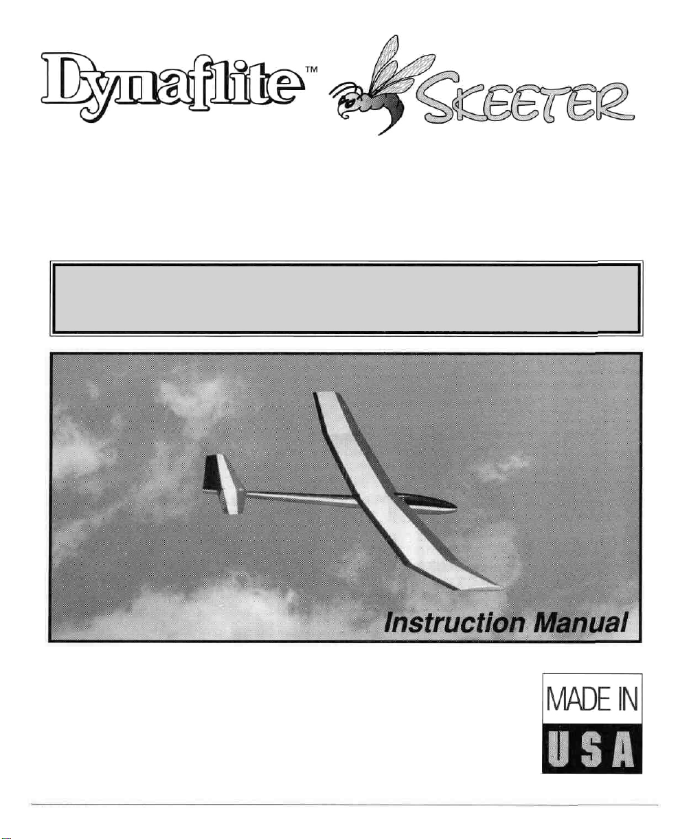
• Easy-to-Build • All Wood Hand-Launched Glider
• 2-Channel Radio Required
(mini servos recommended)
BEFORE STARTING CONSTRUCTION, READ THROUGH THIS INSTRUCTION
MANUAL. IT CONTAINS IMPORTANT INSTRUCTIONS AND WARNINGS
CONCERNING THE ASSEMBLY AND USE OF THIS MODEL.
Dynaflite guarantees this kit to be free from defects in both material and workmanship at the date of
purchase. This warranty does not cover any component parts damaged by use or modification. In no
case shall Dynaflite's liability exceed the original cost of the purchased kit. Further, Dynaflite reserves
the right to change or modify this warranty without notice. In that Dynaflite has no control over the
final assembly or material used for final assembly, no liability shall be assumed nor accepted for any
damage resulting from the use by the user of the final user-assembled product. By the act of using
the user-assembled product, the user accepts all resulting liability. If the buyer is not prepared to
accept the liability associated with the use of this product, return this kit immediately in new and
unused condition to the place of purchase.
SKTRP03 Printed in USA Entire Contents © Copyright 1996
WARRANTY
Page 2
PROTECT YOUR MODEL.
YOURSELF & OTHERS BY
FOLLOWING THIS
IMPORTANT SAFETY
PRECAUTION
Your Skeeter is not a toy, but a sophisticated working
model that functions very much like a full-size
airplane. Because of its realistic performance, the
Skeeter, if not assembled and operated correctly,
could possibly cause injury to yourself or spectators
and damage property.
To make your R/C modeling experience totally
enjoyable, we recommend that you get experienced,
knowledgeable help with assembly and during your
first flights. You'll learn faster and avoid risking your
model before you're truly ready to solo. Your local
hobby shop has information about flying clubs in your
area whose membership includes qualified instructors.
2. You must take time to build straight, true and strong/
3. You must properly install all R/C and other
components so that the model operates properly on
the ground and in the air.
4. You must test the operation of the model before the
first and each successive flight to insure that all
equipment is operating correctly. You must also make
certain that the model has remained structurally sound.
NOTE: We, as the kit manufacturer, can provide
you with a quality kit and great instructions, but
ultimately the quality and flyability of your finished
model depends on how you assemble it; therefore,
we cannot in any way guarantee the performance
of your completed model and no representations
are expressed or implied as to the performance or
safety of your completed model.
You can also contact the national Academy of Model
Aeronautics (AMA), which has more than 2,300
chartered clubs across the country. Through any one
of them, instructor training programs and insured
newcomer training are available. Contact the AMA
at the address or toll-free phone number below.
Academy of Model Aeronautics
5151 East Memorial Drive
Muncie,IN 47302
(800) 435-9262
Fax (317) 741-0057
1. You must assemble the plane according to the
instructions. Do not alter or modify the model, as
doing so may result in an unsafe or unflyable model.
In a few cases the instructions may differ slightly
from the drawings or plan. In those instances you
should assume the written instructions are correct.
INTRODUCTION
Congratulations on your purchase of the Dynaflite
Skeeter. The Skeeter is an attractive, easy to build, all
wood polyhedral Hand Launched Glider (HLG). With
its 55-1/2" inch wingspan and Selig 3021 airfoil, the
Skeeter is a real winner. You will have many hours of
fun with this little ship and never have to chase a
Hi-Start. The Skeeter is easy to build and cover with its
liteweight all balsa conventional construction. The
polyhedral wing, along with simple 2-channel (elevator
and rudder) control make for gentle, forgiving flights.
The Skeeter, with its ideal proportions, is perfectly suited
for small flying sites. So go a head... en joy, and don't let
those little flying sites get in the way of your fun!
At Dynaflite we take pride in offering kits that are
simple and straightforward to build and provide value
for your modeling dollar. Although the Skeeter is small
and easy to build, we recommend seeking the help of
an experienced modeler if this is your first kit. Your local
hobby shop or model club are prime sources of
modeling information.
2
Page 3
Please inventory and inspect all parts carefully
before starting to build! If any parts are missing,
broken or defective, or if you have any questions
about building or flying this model, please call us at
(217) 398-8970 and we'll be glad to help. If you are
calling for replacement parts, please look up the
part numbers and have them ready when calling.
REQUIRED ITEMS
#1 Hobby Knife Handle (XACR4305)
#11 Blades (Qty. 100 - HCAR0311) or
(Qty.5-XACR2911)
Hand or Electric Drill
Drill
Bits:
3/16",
and a 10-24
tap
1/2"
and
9/64"
(or #26)
*0n our workbench/ we have four 11" Easy-Touch™
Bar Sanders/ equipped with #50/ #80/ #150 and
#220-grit sandpaper. This setup is all that is required
for almost any sanding task. Custom sanding blocks
can be made from balsa for sanding hard-to-reach
spots. We also keep some #320-grit wet-or-dry
sandpaper handy for finish sanding before covering.
IMPORTANT BUILDING NOTE: During construction!
you
will
be using a number
various assemblies. Ample material is included but
you should study the plans/ then make an effort to cut
the longest pieces you will need first. Label the pieces
as you cut them for later reference. By doing this
now, you won't have to splice pieces together later,
of balsa
sticks
to frame
Medium T-pins (HCAR5150)
Wax Paper
Clothespins
Masking Tape
1 /2 oz. Thin CA Adhesive - (GPMR6001)
1 /2 oz. Medium CA+ (GPMR6007)
4 oz. Aliphatic Resin (Wood Glue) (GPMR6161)
6-Minute Pro™ Epoxy (GPMR6045)
Bar Sander (GPMR6170) or Sanding Block and
Sandpaper (coarse/ medium, fine grit*)
1 roll film covering plus trim colors
Covering Iron
Straightedge (Fourmost Non-Slip/ FORR2149)
BET READY TO BUILD
1. Unroll the plan sheet. Reroll the plan inside out
to make it lie flat.
Q 2. Remove all parts from the box. As you do,
determine the name of each part by comparing if
with the plans/ instruction manual and parts list
included with this kit. Using a felt-tip or ballpoint
pen/ lightly write the part name or size on each
piece to avoid confusion later. Use the die-cut
patterns shown on page 4 to identify the die-cut
parts and mark them before removing them from the
sheet. Save all leftovers. If any of the die-cut parts
are difficult to punch out/ do not force them! Instead,
cut around the parts with a hobby knife. After
punching out the die-cut parts/ use your bar sander
or sanding block to lightly sand the edges to remove
any die-cutting irregularities or slivers.
LJ 3. As you identify and mark the parts/ separate
them into groups/ such as fuse (fuselage)/ wing/ fin,
stab (stabilizer) and hardware.
3
Page 4
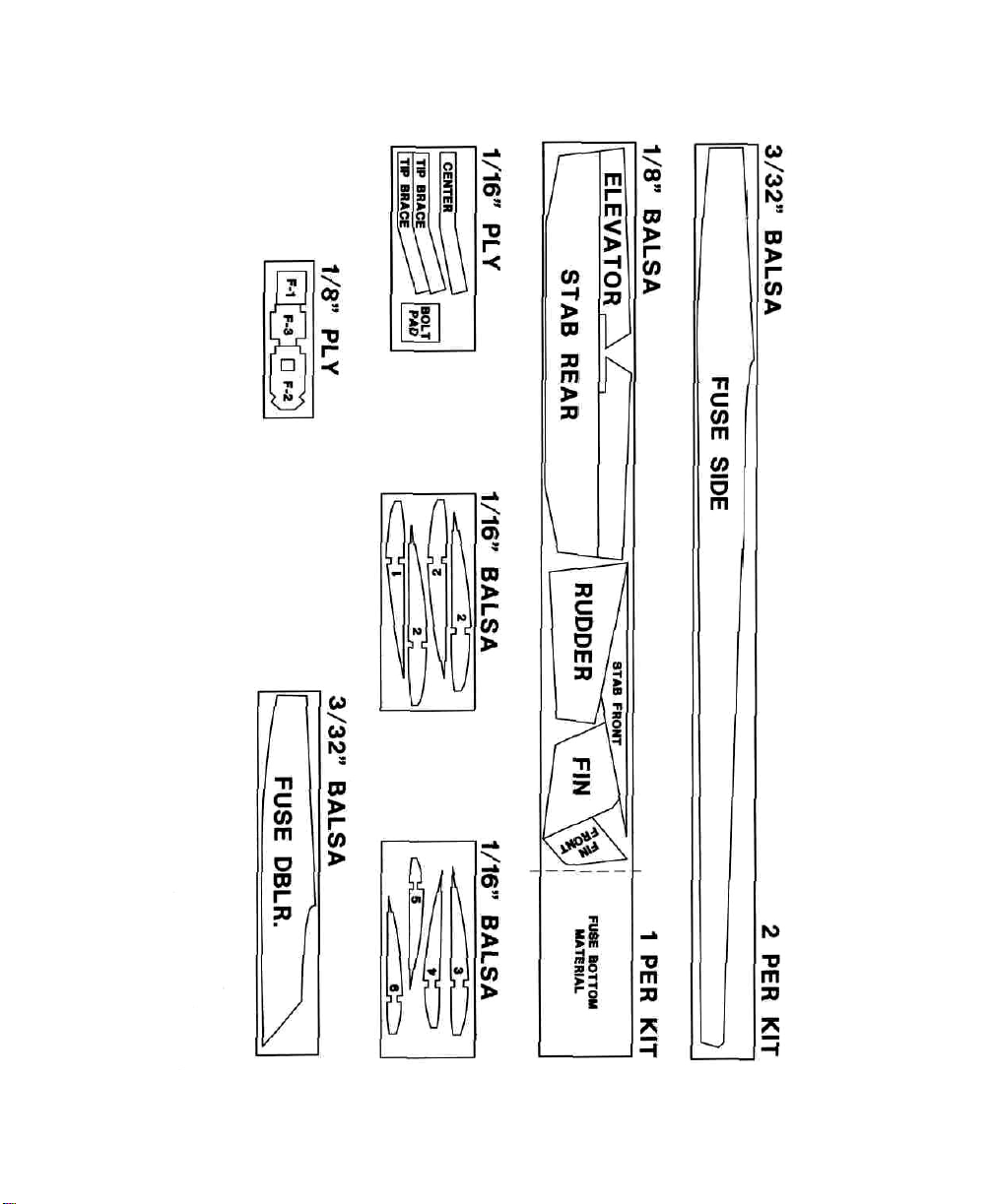
DIE-CUT PATTERNS
4
Page 5

BUILD THE WING
U 1. Start the wing by placing the wing portion of
the plans on the building board. Cover the plans
with wax paper or plastic wrap. This is to prevent
the wing from becoming glued to the plans.
Q 2. Pin the bottom .040" x 15/16" sheet trailing
edge over the drawings.
NOTE: .040" is the thinnest of the sheeting.
Q 3. Pin the 1/8" x 3/16" hardwood bottomspars
over the drawings.
MAIN PANEL / TIP SEPARATION
Q 4. Glue the .040" bottom sheet between the spar
and the trailing edge sheet. Refer to the sketch above.
Q 5. Glue the ribs in place from the center to the tip as
shown on the plans. We will cut the ribs later for the
polyhedral braces. The ribs should fit as shown above.
VERTICAL GRAIN SHEAR WEB
U 7. Cut the shear webs from the 1/16" x 3" balsa
sheet. Glue the shear webs into place between the
ribs. Be sure the grain runs vertically.
NOTE: Do Not install the shear webs where the
polyhedral braces will be installed later.
Q 8. Sand the shear webs so they are flush with the
top of the spar.
Q 9. Glue the 3/16" x 1/4" leading edges to the
front of the ribs.
Q 6. Test fit the top 1 /8" x 3/16" spar into place. If
it doesn't fit properly, enlarge the notches in the ribs
so the spar fits completely in the notch. This is
important so the .040" LE sheet will blend with the
rear portion of the rib. Glue the spar in place with
thin CA.
U 10. Carve and sand the leading edge top to
blend into the ribs. You will probably need to take
the wing off the building board.
5
Page 6

Q 11. Carve and sand the trailing edge sheeting to
accept the upper trailing edge sheeting.
Q 12. Lay the wing back down on the work surface.
Apply thick CA to the area where the top TE is about
to be installed.
Q 13. Install the top TE. Use pins to secure the parts
until the glue dries.
Q 14. With the wing still pinned down, install the
top LE sheet. Cut the .040" x 3" balsa sheeting to the
approximate length. If you haven't put on LE
sheeting with CA before, use the following method:
Apply thick CA to the top spar, ribs and leading
edge. Place the LE sheet into place, and start pinning
down... LET DRY!
Ul 15. Once dry, trim off excess wood at W1, W2
and
the
LE.
Q 16. Prepare the wing for the Polyhedral.
Beginners Note: To avoid difficulties, read this step
through BEFORE cutting and sanding! Refer to the
dimensions on the plans. With each center panel flat
on the work surface, lift the tips so that the bottoms
of
rib
W6
are
2-3/4"
off
the
table.
With
the
tips
blocked up, carefully sand the roots of each tip
panel so they are flush with W2. The final fit should
be tight with no gaps. Take your time while sanding,
removing small amounts at a time.
U 17. Referring to the plans, sand the center and
tip panels to shape as shown.
CUT RIB AS SHOWN
Q 18. Working with the left wing, cut through and
remove 1/16" of rib W2 just behind the spar. This
will make a slot for the polyhedral brace to fit into.
Test fit the die-cut 1/16" ply polyhedral brace in
place as shown on the plans. The polyhedral brace
should contact the top and bottom spars along it's
entire length and the front edge of W2 should touch
the back of the polyhedral brace. If the polyhedral
brace fits, remove the brace and glue the wing tip to
the center panel with CA. If the polyhedral brace
does not fit, slightly adjust its angle with your
sanding block.
Q 19. Using 6-minute epoxy, glue the polyhedral
brace into place. Clothespins work well as clamps
while the epoxy cures. When the epoxy has cured,
glue rib W2 to the polyhedral brace with medium
CA. Repeat steps 18 and 19 for the right wing.
6
still
Page 7

Q 20. Joining the wing panels: Using the same
techniques outlined in steps 16 thru 19, prepare, fit
and glue the two wing panels together using the
die-cut 1/16" ply dihedral brace.
U 6. Hinge the elevator to the stabilizer. Start by
cutting the hinges from the 2" x 9" strip of hinge
material to a size of 1/2" x 1". Snip off the corners
of the hinges for easier insertion.
NOTE: The measurement for blocking up the wing
panels for this step is 3 ".Refer to the plans.
Q 21. Using .040" balsa, sheet the center of the
wing on top. Leave the lower bottom forward section
unsheeted where we will need to get to the W1 ribs
to install the hold down dowel.
Q 22. Glue the 3/16" x 1/2" balsa tip sheets
into place.
Q 23. Sand the wing so the airfoil looks like the
drawing on the plan labeled "typical rib section".
Shape the wing tips as shown on the plan.
BUILD THE TAIL GROUP
U 1. Remove the die-cut stabilizer, elevator, fin and
rudder from their die-cut sheets. Refer to the die-cut
layout for identification.
Q 2. Start assembly by joining the stab front to the
stab. Using your sanding block, remove any die-cut
irregularities. When they mate to your satisfaction,
use CA to glue the two parts together. Sand the joint
to obtain a smooth surface.
Lt 7. Now use your knife to cut the slots into the
stab and elevator at the hinge locations shown on
the plans. CAUTION: Do this slowly. The wood is
thin. It is best to use many small cuts to get the
required depth. Test fit the hinges by joining both
parts. Make sure the bevel will allow the elevator to
move adequately up and down. Do not glue the
hinges in place until the model is covered.
Q 8. Sand the stab to the approximate airfoil shape
as shown in the cross section on the stab drawing.
Q 9. Glue the rudder front to the rudder.
U 10. Bevel the leading edge of the rudder
Q 11. As before/ install the hinges to the fin and rudder.
Q 12. Sand the fin and rudder to a nice thin
airfoil shape. Set these parts aside and move on to
the fuselage.
BUILD THE FUSELAGE
Q 3. Tape the elevators to the stab.
U 4. Cut a piece of leftover spar material to fit into
the tie bar area between the elevators. When it fits
to your satisfaction glue it in place. Be careful not to
glue the elevator to the stabilizer!
Q 5. Remove the elevator from the stab and bevel
its LE as shown in the cross section on the plan. This
will allow for proper movement.
Q 1. Cover the fuselage section of the plans with wax
paper or plastic wrap. Start the fuselage by aligning a
die-cut 3/32" balsa doubler over the inside of a diecut 3/32" balsa fuse side. Align the doubler at the
front and top. When everything is aligned, glue the
doubler to the fuse side by applying thin CA around
the perimeter of the doubler. Be sure to make both a
left and a right side.
7
Page 8

Q 2. Glue the 1/4" sq. top and bottom longerons
into place.
Q 3. Drill or cut and file a 1 /2" hole in the center of
F3. This will allow the pushrods to pass through it.
Lay the sides over the plans and mark the location of
the F2 and F3 fuselage formers.
1/8" THICK
Q 4. Taper the 1 /4" sq. longerons at the rear of the
fuselage with a sanding block so when the
bulkheads are installed the tail will pull together to
measure about 1/8" thick.
Q 10. Starting at the nose/ cut and glue 3 pieces of
1/8" balsa bottom sheeting as shown on the plans.
[-ll1.
Glue
the
1/16"
place. Do not sheet the top yet, we will need to
install the pushrods first.
Q 12. Find the 1/2" x 1-3/8" x 1-1/4" block that
fits cross grain in front of the canopy. Sand a bevel
to the approximate angle shown on the plan.
Q 13. Glue the block into place.
Q 14. Sand the front flat and glue the nose block
into place
Ql 15. Glue the tow hook block into place. It fits
between the two 1/4" sq. longerons and against the
bottom sheeting.
U 16. Cut a small exit hole on either side of the fuse
near the tail for the pushrod guide tubes.
balsa
bottom
sheeting
into
LJ 5. Using a small triangle, glue F2 and F3 to the
left fuse side at a 90-degree angle. See section AA
on the plans for bulkhead orientation.
1— 6. Glue the right fuse side to F2 and F3.
Q 7. Pull the fuse together at the tail and glue
into place.
LJ 8. Pull the fuse front together and glue F1 into place.
Ul 9. With your sanding block/ sand the top and
bottom flat to accept the 1/16" and 1/8"
balsa bottom.
U 17. Slide the pushrod guide tubes into the slots at
the rear, then through F3 and F2. Leave the tubes as
they are until you install the radio.
Q 18. Sheet the rear top of the fuse with 1/16"
balsa. Do not sheet the area where the stabilizer will
mount.
Q 1 9. Cut or sand a bevel at one end of the
hatch/canopy block so it will fit with the cross grain
block already installed.
Q 20. Hollow out the hatch/canopy block so that it
just clears F2, and sits flat on the fuselage.
8
Page 9

Q 21. Tack glue the hatch/canopy block into place
with about 4 drops of CA. This will hold it in position
while the front of the fuse is being shaped.
Q 22. Carve and sand the fuselage to a nice round
shape. Section AA and CC shows approximately
what you should try to achieve. Do not carve the
wing or stab mount areas!
Q 23. Glue the 1/8" ply wing bolt mount into
position as shown on the fuselage drawing.
FINAL ASSEMBLY
Q 1. Cut the canopy block loose with your knife. Set
the canopy aside.
Q 2. Place the wing on the fuselage in the position
shown in the plans. Push the leading edge up
against F2.
Q 3. Drill a 3/16" hole through F2 and into the
leading edge and rib W1.
Q 7. Remove the wing and apply 6-minute epoxy to
the front dowel at W1. Before the epoxy cures,
reinstall the wing so it will set in the proper location.
NOTE: Be careful not to glue the wing to the fuselage!
1-1 8. Pin the stabilizer to the fuselage. Sight down
the fuse from the rear making sure the stabilizer is
parallel to the trailing edge of the wing. You may
need to sand the stab mount area so the stab sits flat
on the fuse. When everything looks good, glue the
stab to the fuse with medium CA.
Q 9. Pin the fin to the centerline of the stab. Use a
90-degree triangle to make certain that the fin is
perpendicular to the stab and centered, when viewed
from the back. When satisfied that the fin is centered
and straight, glue it in place using medium CA.
U 10. Use a piece of 1 /4" sq. leftover balsa from the
fuse longerons to cut triangular sticks to fit where the
stab and fin intersect. Glue them in place with CA.
This should finish the basic construction. Cover your
"Skeeter" according to the instructions included with
the covering of your choice.
Ul 4. Before you glue the dowel, let us install the
rear bolt. Start by aligning the wing with the
fuselage. Use a measuring tape to measure the
distance from the wing tip to the tail of the fuselage.
LI 5. When both the left and right sides are equal/
use a #26 or 9/64" drill to drill a hole through the
wing and the 1/8" ply wing bolt mount. See the
fuselage drawing for the proper location.
Q 6. Use a 10-24 tap to thread the wing bolt mount.
Apply a couple of drops of thin CA to the threads to
harden them. When dry, run the tap through the
threads again.
RADIO INSTALLATION
Q 1. At this point the pushrod guides are in place.
You will need to test fit your servos before you cut
the guides to their final length.
9
Page 10

1—1 2. Based on the servo location, cut the pushrod
guide tubes to fit. Leave enough room for the servo
output attachment. Use 1/16" wire for this.
the coupler). Now, measure another 1/2" toward
the elevator on the pushrod wire and make another
mark. Trim the pushrod wire at the second mark.
Z-BEND
Ul 3. When you have the forward part of the
pushrod bent and attached/ slide the wire into the
tube from the front. Then mount the servos using
double-sided tape.
Q 4. Use CA to glue the guide tubes to the fuselage
formers and the rear of the fuse.
LI 5. Trim off and sand the excess guide tubes flush
with the fuse sides.
Bend the wire between the two marks as shown in
the sketch. Remove the clevises from the control
horns and unscrew the clevis from the coupler. Slide
the coupler onto the wire and carefully solder the
coupler to the wire. Reassemble the clevises and
reattach them to the control horns.
Q 8. Mount the battery in the front of the fuse. If
you can fit any foam around the battery, use it to
keep the battery in place.
Ul 9. Glue the 1/16" plywood tongue to the bottom
front of the canopy, as shown on the fuse plan.
Ul 10. To hold the canopy down, simply use a piece
of tape on both sides.
Q 11. Mount the receiver and check the direction of
the control surface movement.
LJ 6. Before attaching the threaded shaft and clevis,
install the control horns using two 2-56 x 5/8"
screws each.
OR
Q 7. Turn on the radio and center the servos.
Thread a nylon clevis onto a threaded solder coupler
at least 10 turns. Attach a clevis/coupler assembly to
the rudder and elevator control horns. Align the
coupler with the pushrod wire (making sure the
rudder and elevators are centered) and mark the
wire at the back of the coupler (where it would enter
Q 12. Check the balance. A good place to start is
on the spar. Move the center of gravity (C.G.) to
your liking - remember if you move the C.G. back
the model will become more sensitive in pitch, to the
point that it snap rolls, so go slowly.
IMPORTANT
If this is your first model we recommend you now enlist
tne help of an experienced modeler and
so
will
assure a more
successful
local hobby dealer or R/C club is a great source of
assistance if you don't already know someone into R/C.
10
Test
Pilot.
first
experience. Your
Doing
Page 11

Airfoil - A curved structure designed to create lift by
the reaction to air moving over its surface.
AMA - Academy of Model Aeronautics
A.R. - Aliphatic Resin glue (wood glue).
Pushrods - Wooden or wire rods which transfer
motion from the electronic servos to the aircrafts
control surfaces.
Rib - A structural member which maintains the
contour of the wing surface.
Rudder - The vertical control surface hinged to the
fin and used to control yaw about the vertical axis.
Bulkhead - A structural member in the fuselage used to
strengthen and establish the shape of the cross section.
CA - Cyanoacrylate glue
C.G. - Center of Gravity
Clevis - Used to attach the pushrods to the control
surfaces through a control horn.
Control horn - A lever projecting from a control
surface which translates motion from the pushrod
and clevis.
Die-cut - Parts of sheet wood that are precut so the
modeler can use them with a minimum of preparation.
Dihedral - The angle formed by the wing panels
where they intersect.
Doubler - Part of the structure that is used to
reinforce a member by lamination.
Elevator - The horizontal moving surface hinged to
the stabilizer. Used to raise and lower the tail in
flight, thus causing the aircraft to pitch about the
lateral axis.
Slope soaring - the art of remaining aloft in a glider
or sailplane by utilizing the vertical components of
air currents caused by wind being deflected up and
down a cliff or hill.
Spar - The principle spanwise structural member of a
wing or stabilizer.
Tierod - Structural member that connects two halves
of a split elevator.
Trailing edge - (TE) The rearmost edge of the wing,
stabilizer, fin, etc...
Towhook - a device used to connect the tow line to
the aircraft during lunch.
DYNAFLITE BUTTERFLY.
.DYFA1010
Fin - The fixed vertical stabilizer
Fuselage - (fuse) The structure of an airplane to
which the wings and tails are attached.
Glider - A heavier-than-air unpowered aircraft.
Leading edge - (LE) The forward edge of a wing,
stabilizer, fin etc...
The Butterfly is a "powered sailplane" or "motor
glider" and is an ideal model for learning to fly radio
controlled models. Because of its large wingspan and
light wing loading, the Butterfly is a gentle model that
will give you plenty of time to think and react. The
Butterfly does not require a powerful engine. Any .10
to .15 cu. in. 2-stroke will do the job - all the engine
has to do is provide a little thrust and the large wing
will do the rest!
11
Page 12

FLIGHT LOG
DATE
COMMENTS
Started Construction
Finished Construction
First Flight
 Loading...