

Page 1
TM
TM
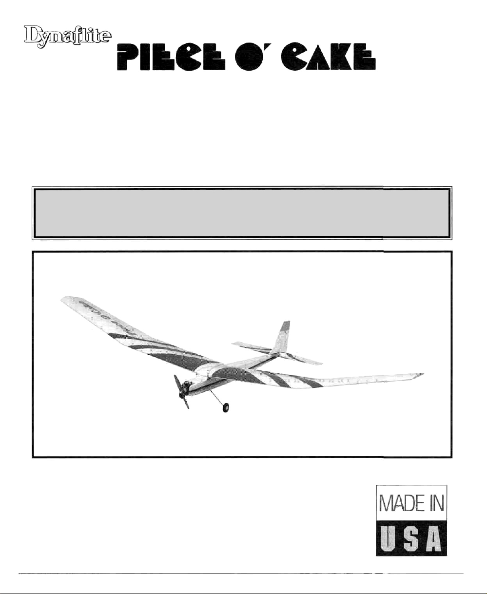
• EASY TO BUILD...EASY TO FLY
• FORGIVING FLIGHT CHARACTERISTICS
LARGE WINGSPAN • LIGHT WING LOADING
READ THROUGH THIS INSTRUCTION MANUAL FIRST. IT CONTAINS
IMPORTANT INSTRUCTIONS AND WARNINGS CONCERNING THE ASSEMBLY
AND USE OF THIS MODEL.
.049 POWERED MOTOR GLIDER
Instruction Manual
Dynaflite guarantees this kit to be free from defects in both material and workmanship at the date of
purchase. This warranty does not cover any component parts damaged by use or modification. In no
case shall Dynaflite's liability exceed the original cost of the purchased kit. Further, Dynaflite reserves
the right to change or modify this warranty without notice. In that Dynaflite has no control over the
final assembly or material used for final assembly, no liability shall be assumed nor accepted for any
damage resulting from the use by the user of the final user-assembled product. By the act of using
the user-assembled product, the user accepts all resulting liability. If the buyer is not prepared to
accept the liability associated with the use of this product, return this kit immediately in new and
unused condition to the place of purchase.
POCKP03 Printed in USA Entire Contents © Copyright 1996
WARRANTY
Page 2
Introduction.....................................................2
Precautions......................................................3
Preparations...................................................3
Required
Setting
Required Supplies & Tools................................4
Optional Accessories.......................................4
Building
Common Abbreviations...................................5
Types
A Note About Cyanoacrylate Glue...................6
Metric Ruler................................................... 6
Build
Build
Build The Fin, Stabilizer & Elevator...................8
Finish The Tail Surfaces....................................8
Build
Build
Build
Prepare
Join The Inner Wing Panels............................17
Join The Outer & Inner Wing Panels...............18
Finish
Build
Build
Prepare
Join
Sheet The Bottom Of The Fuselage..................22
Install The Firewall........................................22
Install
Sheet The Top Of The Fuselage.......................24
Mount The Landing Gear...............................26
Mount
Align
Align
Align
Covering........................................................30
Prepare The Model For Covering....................30
Covering
How
Covering
Final Construction...........................................33
Shape The Flying Surfaces.............................33
Join
Hinge The Control Surfaces............................34
Accessories
Up
Shop..............................................4
Notes................................................5
Of
Wood...............................................5
The
Tail
Surfaces
The
Rudder.............................................7
The
Wing...............................................10
The
Inner
The
Outer
The
Panels
The
Wing............................................
The
Fuselage..........................................
The
Formers
The
Fuselage
The
Fuselage
The
Servos & Pushrod
Your
Engine.......................................27
The
Tail
Group......................................28
The
Stab..............................................28
The
Fin
................................................29
Tips
...............................................30
To
Cover
Your
Sequence
The
Tail
Surfaces
......................................3
......................................7
Wing
Panels
..........................10
Wing
Panels
.........................15
For
Joining
.........................................19
Sides
Sides.................................20
Model
.......................................32
To
......................17
...........................19
Guides...............23
.............................30
The
Fuselage
............33
18
19
Fuelproofing.................................................34
Final Hook
Connect
Finish
Balance
Set The Control Throws..................................38
Preflight.........................................................39
Charge
Ground
Gather
Range
Engine
Flying
Find A Safe
Takeoff.........................................................41
Flight...........................................................41
Landing.......................................................42
Congratulations and thank you for purchasing the
Dynaflite Piece 0' Cake. The Piece 0' Cake is a
"powered sailplane" or "motor glider" and is an ideal
model to learn radio controlled flying - especially if
you are not able to locate an experienced flight
instructor and must try it on your own. Because of its
large wingspan and light wing loading, the Piece 0'
Cake is a gentle model that will give you time to think
and react. For the same reasons/ you must reserve
first flight attempts for a calm day - more on that in
the "Flying" section at the end of the manual. The
Piece 0' Cake does not require a powerful engine.
Any .049 will do the job - all the engine has to do is
provide a little thrust and the large wing will do
the rest!
The way you fly the Piece 0' Cake is to let it climb (it
will
do
from you) and fly it around rather like a sailplane.
This doesn't sound like much action but don't worry; if
you're a beginner you'll be busy. Most important,
you'll develop the hand/eye coordination required to
fly traditional sport/trainers. Enough said. Please read
the rest of the preliminary information thoroughly,
then let's get started!
2
Ups & Checks................................35
The
Servos.......................................35
Installing
Your
The
Check
Your
Check
Safety
............................................................41
that
The
Radio..............................36
Model
......................................38
Batteries
Tools..........................................39
The
Precautions...............................40
Place
almost
.....................................39
The
Model..............................39
Radio.................................40
To
Fly
................................41
by
itself
with
just
a little guidance
Page 3
Your Piece 0' Cake is not a toy, but a sophisticated
working model that functions like a full-size airplane.
Because of its performance, if you do not assemble
and operate the Piece 0' Cake correctly, you could
possibly injure yourself or spectators and damage
property. To make your R/C modeling experience
totally enjoyable, we recommend that you get
assistance with assembly and your first flights from
an experienced, knowledgeable modeler. You'll
learn faster and avoid risk to your model before
you're truly ready to solo. Your local hobby shop has
information about flying clubs in your area whose
membership includes qualified instructors.
You can also contact the national Academy of Model
Aeronautics (AMA), which has more than 2,300
chartered clubs across the country. We recommend
you join the AMA, which will provide you with
insurance coverage at AMA club sites and events.
AMA Membership is required at chartered club
fields where qualified flight instructors are available.
3. You must install all R/C and other components so
that the model operates properly on the ground and
in
the
air.
4. You must test the operation of the model before the
first and each successive flight to insure that all
equipment operates correctly. You must also make
certain that the model has remained structurally sound.
NOTE: We, as the kit manufacturer, can provide you
NOTE: We, as the kit manufacturer, can provide you
with a quality kit and great instructions, but
with a quality kit and great instructions, but
ultimately the quality and flyability of your finished
ultimately the quality and flyability of your finished
model depends on how you assemble it; therefore,
model depends on how you assemble it; therefore,
we cannot in any way guarantee the performance
we cannot in any way guarantee the performance
of your completed model and no representations are
of your completed model and no representations are
expressed or implied as to the performance or
expressed or implied as to the performance or
safety of your completed model. Please inventory
safety of your completed model. Please inventory
and inspect all parts carefully before starting to
and inspect all parts carefully before starting to
build! If any parts are missing, broken or
build! If any parts are missing, broken or
defective or if you have any questions about
defective or if you have any questions about
building or flying this model, please call us at
building or flying this model, please call us at
(217) 398-8970 and we'll be glad to help. If you
(217) 398-8970 and we'll be glad to help. If you
are calling for replacement parts, please look up the
are calling for replacement parts, please look up the
part numbers and have them ready when you call.
part numbers and have them ready when you call.
Contact the AMA at the address or toll-free phone
number below.
Academy of Model Aeronautics
5151 East Memorial Drive
Muncie, IN 47302
(800) 435-9262
Fax (317) 741-0057
1. You must assemble the plane according to the
instructions. Do not alter or modify the model, as
doing so may result in an unsafe or unflyable model.
In a few cases the instructions may differ slightly
from the photos or plan. In those instances the text
should be taken as correct.
2. You must take time to build straight, true and strong.
REQUIRED ACCESSORIES
These are the items not included with your kit that
you will need to purchase separately. Items in
parentheses (OSMG2691) are suggested part
numbers recognized by distributors and hobby
shops and are listed for your ordering convenience.
GPMis the Great Planes® brand, TOP is the Top
Flite®
brand and
2 or 4 Channel Aircraft Radio System with
2 standard servos and a square battery*
Q .049 Engine with appropriate fuel and glow
plug clip
3
HCA
is
the
Hobbico®
brand.
Page 4
Engine Mount (DAVG3005)
Propellers - Refer to your engine's instructions
for proper size
1 roll of Covering Film; See Covering Tips
(page 30)
1 /4" Latex Rubber Padding (HCAQ1000)
1/16" Foam Wing Seating Tape (GPMQ4422)
(2) 1-1/2" Wheels (GPMQ4243)
(2) 3/32" Wheel Collars (GPMQ4302)
#64 Rubber Bands (1 /4 Ib box - HCAQ2020)
(4) #2 x 3/8" Screw for mounting your engine
Self-Adhesive Lead Weight (GPMQ4485)
*lf your radio includes a "flat" style battery for the
receiver, ask your hobby dealer if you can swap it
for a square style. The square style battery fits in the
fuselage better than a flat one.
SETTING UP SHOP
CA Activator - (GPMR6035)
30-Minute Pro Epoxy - (GPMR6047)
#1 Hobby Knife Handle (XACR4305)
#11 Blades (Qty. 100 - HCAR0311) or
(Qty.5-XACR2911)
Hobbico (or similar) Builders Triangle
(HCAR0480)
Medium T-pins
Wax Paper
Electric Drill
Drill
Bits:
Masking Tape
String for aligning the stabilizer
#1 Phi Hips Screwdriver
Top Flite Covering Iron (TOPR2100)
A building board that you can stick pins into
(see "Setting Up Shop")
1/16",
(HCAR5150)
3/32"/
1/8"/
3/16
11
If this is your first model there are a few supplies and
tools that you should gather before you begin. The
most important item is a flat table that you can build
your models on. You can turn a solid core door into
a building table, but avoid hollow core doors
because they warp easily. If possible, locate your
building table in an area that is not in the way of
other projects or household activities. Cover your
building table with a board that you can stick pins
into. The back of a 2' x 4' ceiling tile works well or
you can cut a piece to fit your table from a 4' x 8'
sheet of Celotex insulation board available from a
home improvement store.
REQUIRED SUPPLIES
AND TOOLS
These are the building tools and adhesives that you
will need to build your Piece 0' Cake.
We recommend Great Planes Pro™ CA and Epoxy
2 oz. Thin CA Adhesive - (GPMR6003)
2 oz. Medium CA+ Adhesive (GPMR6009)
OPTIONAL ACCESSORIES
You can build your Piece 0' Cake without these items
but they will make the job much easier and provide you
with better results. These are things you will accumulate
as your building "career" progresses anyway.
Razor Plane (MASR1510)
Single-Edge Razor Blades (100, HCAR0312)
CA Applicator Tips (HCAR3780)
Hot
Sock™
(for your covering
6-Minute Pro Epoxy (GPMR6045)
Trim Seal Tool™ (TOPR2200)
Heat Gun (TOPR2000)
Straightedge (Fourmost Non-Slip, FORR2149)
Denatured or IsopropyI Alcohol (for epoxy
clean-up) '
HobbyLite™ Balsa Filler (HCAR3401)
Epoxy Brushes (GPMR8060)
CA Debonder (GPMR6039)
Powered hand tool with Sanding Drum and
Cut-off Wheel
Bar Sander or Sanding Block and Sandpaper
(coarse, medium, fine grit)*
Microballoons Filler (TOPR1090)
4
iron,
TOPR2175)
Page 5
*A flat, durable, easy-to-handle sanding tool is a
necessity for building model airplanes. Great Planes
makes a complete range of Easy-Touch™ Bar Sanders
and replaceable Easy-Touch adhesive-backed
sandpaper. For the Piece 0' Cake all that is required
is the short 5-1/2" Bar Sander (GPMR6169) and
two assortment packages of adhesive-backed
sandpaper (GPMR6189).
For future reference, here's a list of Easy-Touch Bar
Sanders and adhesive-backed sandpaper:
5-1/2" Bar Sander (GPMR6169)
11 "Bar Sander (GPMR6170)
22" Bar Sander (GPMR6172)
Machine screws are designated by a number,
threads per inch and a length.
For example 2-56 x 3/8"
When you see the term "test fit" in the
instructions, it means you should first position the
part on the assembly without using any glue,
then slightly modify or "custom fit" the part as
necessary for the best fit.
Whenever
either 30-minute epoxy or 6-minute epoxy. When
30-minute epoxy is specified, it is highly
recommended that you use only 30-minute epoxy
because you will need either the working time
and/or the additional strength.
just
"epoxy"
is
specified
you
may
use
COMMON ABBREVIATIONS
Assortment pack of 5-1/2" strips (GPMR6189)
12' Roll of adhesive-backed sandpaper,
80-grit (GPMR6180)
150-grit (GPMR6183)
220-grit (GPMR6185)
• There are two types of screws used in this kit:
Sheet metal screws are designated by a number
and a length.
For example #2 x 3/8"
Fuse = Fuselage
Stab = Horizontal Stabilizer
LE = Leading edge (front)
TE = Trailing edge (rear)
Ply = Plywood
" =Inches
Balsa Basswood Plywood
5
Page 6
The most popular type of glue modelers use for
general construction of R/C models is cyanoacrylate
or CA glues. Modelers build with CA because it
cures fast (immediately in some cases) and the
pieces do not have to be clamped or pinned together
as they do with traditional adhesives. CAs do,
however, have their own set of special procedures
and precautions that you should follow. Always use
CA in a well ventilated area. Open some windows
or place a fan in the room to circulate the air. Do not
lean directly over your work when you use CA and
look away while it cures or "sets off." CA can cure
immediately upon contact with skin so if you
accidentally bond your fingers, do not use vigorous
motion to separate them. Use CA Debonder
(GPMR6039) or acetone (nail polish remover) or
soak your fingers in warm water for a few minutes.
Never point the tip of a CA bottle toward your face
and be especially careful when you unclog a CA tip.
Hobbico CA Applicator Tips (HCAR3780) are highly
recommended and will help keep the bottle from
clogging. Keep paper towels or tissues close by to
immediately absorb excess CA dropped on your
model or work area. Read all the warning labels on
your CA bottle.
glue to one part, then join it to another. Thick CA is
great for glue joints that don't fit perfectly or parts
that require a little time for positioning before the
glue cures. You will encounter many other conditions
that require one or the other types of CA. For the
Piece 0' Cake all you really need is thin and
medium CA.
CA Accelerator is a chemical that you can spray
over uncured CA to make it cure immediately. A mist
spray of accelerator will do the job. Do not inhale
the vapors! Some modelers "preprime" the parts to
be glued with accelerator, join them, then add the
CA. This way the CA is guaranteed to cure
immediately. This prepriming is especially handy
when you use thin CA because it will cure before all
of the glue soaks into the wood away from the glue
joint. We do not recommend you build your entire
model with this method. Use accelerator only when
necessary. Often, overspray from accelerator used
hours or even days earlier on nearby glue joints will
cause the CA you use on the next step to cure
prematurely and unexpectedly - so be careful!
There are different viscosities of CAs intended for
different conditions you will encounter when you
build. Thin CA is great for "tack-gluing," for glue
joints that fit well and for parts that are already
joined but need to be permanently bonded. Medium
CA is used for general construction where you apply
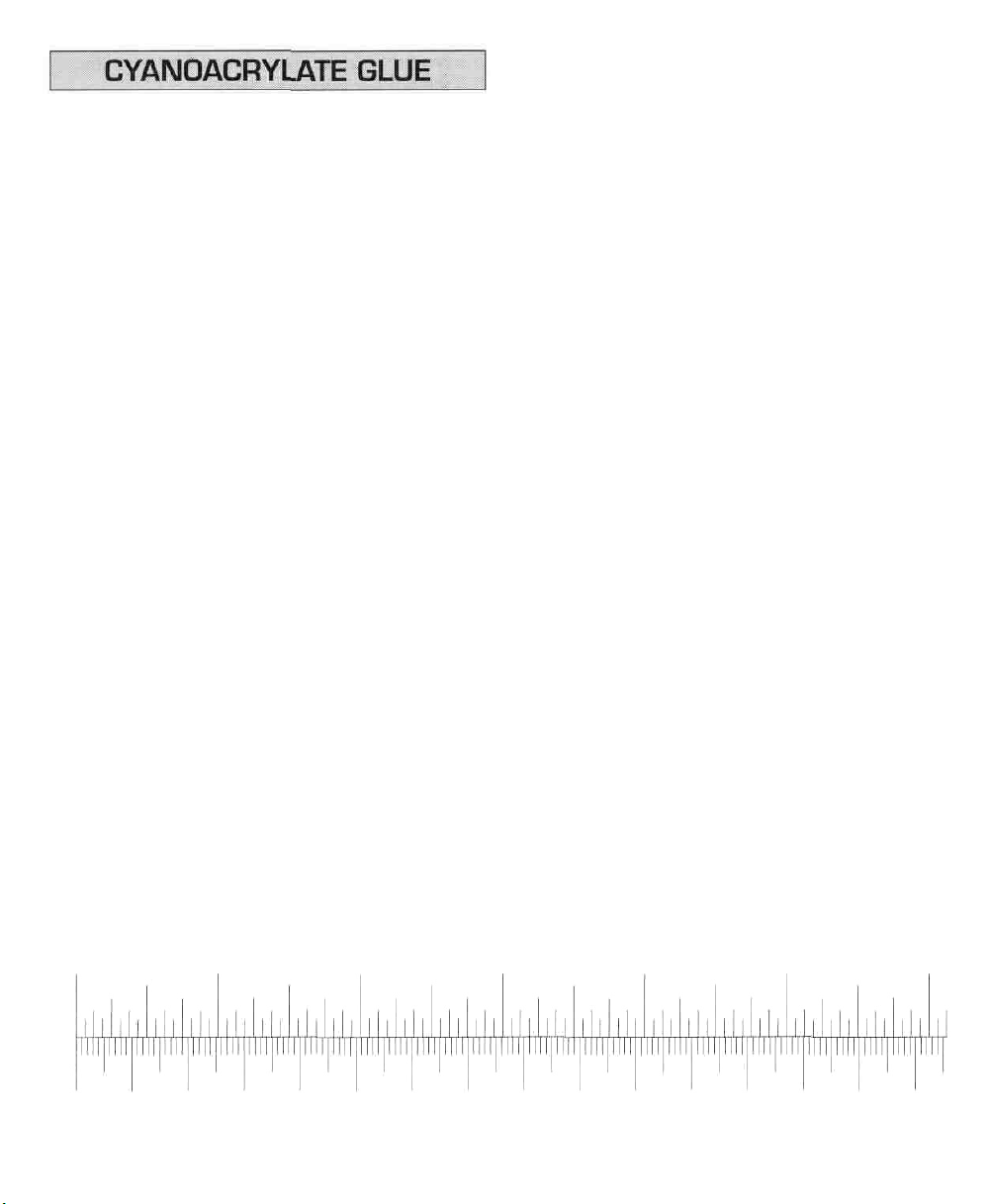
Inch Scale
0"
1"
0
10
20
2"
30
40
3"
50
60
70
Metric Scale
4"
80
90
100
6
5"
110
120
130
6"
140
150
Page 7
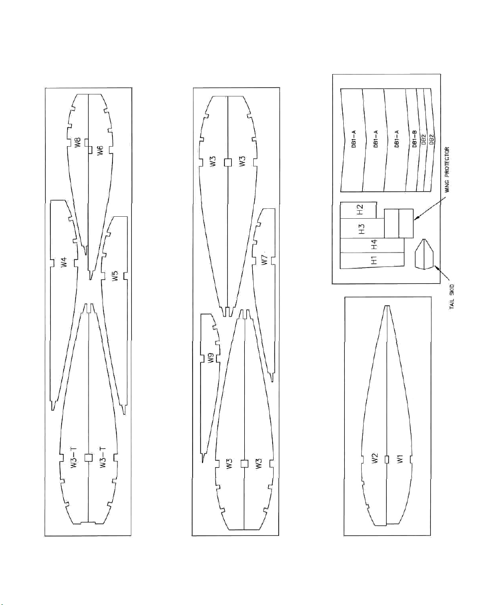
DIE-CUT PATTERNS
7
Page 8
Place your building board on top of your flat
building table. Unroll the plan sheet, then reroll it the
opposite way so it will lay flat. Position the rudder
and fin drawing over your flat building board. You
may separate the wing portion from the plan, or fold
the plan in half to make it easier to work with. Cover
the rudder and fin drawing with wax paper so the
glue will not stick to the plan.
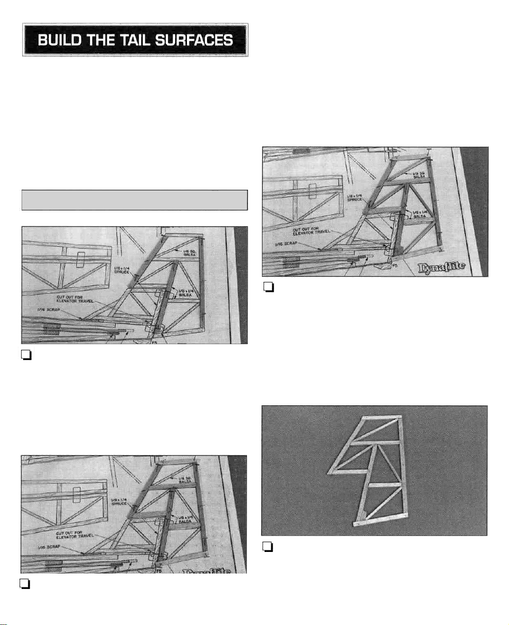
BUILD THE RUDDER
position with medium CA. Where possible, cut the
sticks slightly too long so you can trim them to exact
length as you complete the assembly. You can cut the
tip and bottom pieces too long, and trim them after
you remove the rudder from the plan.
L-l 3. Make the rudder horn mount plate from the
1/8" x 1/4" balsa stick, then glue it in position with
medium CA. Accurately cut the "braces" from a
1/8" x 1/8" x 36" balsa stick, then place them in
the frame and glue them in position with thin CA.
LJ 1. Accurately cut the three vertical rudder pieces
including the leading edge (LE), rudder post (the
middle part) and the trailing edge (TE) from a 1 /8"
x 1/4" x 36" balsa stick. Then pin them over their
locations on the plan with small T-pins. Many
modelers find that they can more accurately cut
small balsa sticks with a single-edge razor blade
instead of a hobby knife.
LJ 2. Cut the five horizontal rudder pieces from the
same 1/8" x 1/4" balsa stick, then glue them in
LJ 4. Remove the T-pins, then lift the rudder from
your building board and peel off the wax paper.
Reinforce glue joints that don't look strong with
medium CA, then set the rudder aside and continue
with the rest of the tail pieces.
8
Page 9
BUILD THE FIN,
STABILIZER & ELEVATOR
Q 1. Use the remainder of the 1/8" x 1/4" balsa
stick plus three more 1 /8" x 1 /4" x 36" balsa sticks,
and the remainder of the 1/8" x 1/8" balsa stick
plus a second 1/8" x 1/8" x 36" balsa stick, to
build the fin, stab and elevator the same way as the
rudder. Remember, where possible it's easier if you
cut the sticks slightly long so you can trim them to
exact length after you remove the assembly from
your building board. After you complete each
assembly, remove it from your building board and
reinforce any glue joints that don't look strong with
medium or thin CA.
Note:
Make
sure
you
use
the
1/8" x 1/4" x 3-1/2"
basswood stick for the fin trailing edge. Make the
stab center from the 1 /8" x 1" x 2-3/4" balsa sheet.
Cut the angles to match the leading edge first, then
trim the stab center to the length shown on the plan.
A note about sanding "built-up" tail surfaces:
Use care when you sand a lightweight balsa
structure made up of "sticks." The part flexes and
moves while you sand, and it can be difficult to
keep your sanding block flat so you do not snag
any of the small braces, or over-sand one area
and make it thinner than another. Due to the
design and slow flying speed of the Piece 0' Cake,
a perfectly smooth finish is not necessary. For this
model, the purpose of sanding is just to remove
any glue bumps or uneven edges. Stop sanding
when you have reduced most of the high spots.
Use a large sanding block or a flat bar sander,
and
do
not
apply
much
pressure
Enjoy it's not a racing plane - it's a floater.
Q 2. Use a ballpoint pen to lightly mark the location
of the hinges on the control surfaces where shown
on the plan.
while
you
sand,
FINISH THE TAIL SURFACES
LJ 1. See the note below/ then use your bar sander
or a sanding block and 220-grit sandpaper to even
the edges and blend the LE's, TE's and "braces" of
all the tail surfaces so they are flat and smooth.
Q 3. Use a hobby knife with a #1 1 blade to
carefully make the hinge slots. The first several cuts
should be just deep enough to make a shallow slit to
establish the hinge slot location.
9
Page 10
CUT HINGE SLOT
WITH HOBBY KNIFE
AND No. 11 BLADE
After the first shallow cuts, make several more cuts
going slightly deeper each time. Move the knife from
side to side and widen the slot as you cut.
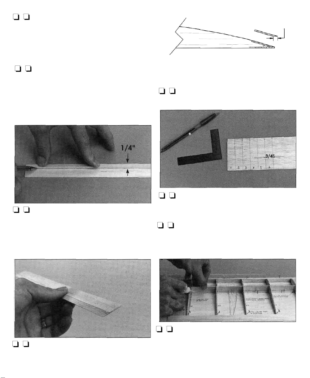
Q 6. Carefully separate the elevator from the stab.
Then use a ballpoint pen and a straightedge to
lightly draw a line 1/16" from the leading edge on
both sides of the elevator.
7/16"
3/4"
MAKE SIX 7/16" X 3/4" HINGES FROM
THE 2" X 9" HINGE STRIP PROVIDED
Q 4. Cut six hinges from the hinge material
supplied as shown in the sketch. Snip the corners off
so the hinges go into the slots easier.
Q 7. Use the lines as a guide to bevel the leading
edge of the elevator to a "V" with a hobby knife or a
bar sander and 220-grit sandpaper.
LJ 8. Bevel the leading edge of the rudder the same
way you did the stab.
Q 9. Use your bar sander and 220-grit sandpaper
to round the perimeter of the tail surfaces as shown
on the plan (except of course, the edges that are
joined by hinges).
There, that was a "piece o' cake," wasn't it? Set the
tail surfaces aside for now while you build the wing
and the fuselage.
U 5. Test join the elevator to the stab, and the
rudder to the fin with the hinges. Adjust the hinge
slots if necessary so the control surfaces fit well.
10
Page 11
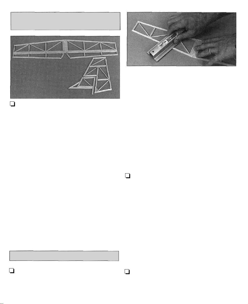
BUILD THE INNER WING PANEL
U 1. Before you remove the the die-cut 3/32" balsa
ribs and the die-cut 1/16" plywood parts from their
die sheets, mark them with a ballpoint pen as shown
on page 7. If you plan on covering the wing with
transparent film, neatly mark all the ribs in the same
location, or mark them in an inconspicuous location
so the marks will not be seen through the covering.
Q 2. Carefully remove all the ribs and the plywood
parts from their die sheets. If a rib will not easily
come out of the die sheet, do not force it but use a
sharp #11 blade to cut the wood where necessary.
Use a bar sander and 220-grit sandpaper to remove
any slivers or die-cutting irregularities.
Ql Q 3. Build the right inner wing panel first so
your progress matches the photos. Cut the wing
portion from the plan, or fold the plan so the right
wing panel is on top. Lay the right wing plan over
your building board, then cover it with wax paper.
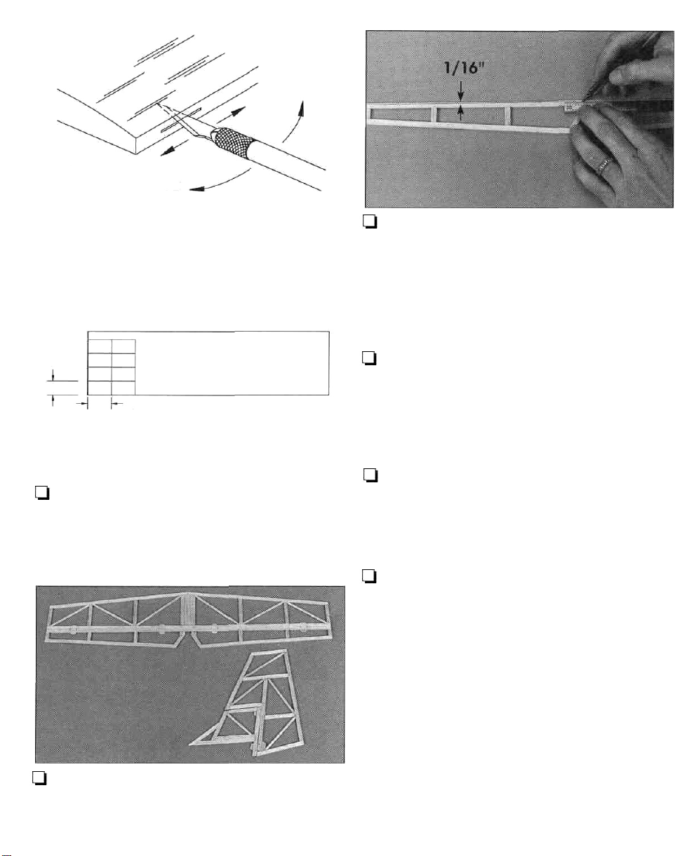
U U 5. Accurately cut a 1/16" x 15/16" x 36"
balsa sheet to a length of 1 8". Then pin it in position
over the trailing edge of the plan so the root end
aligns with the centerline.
LJ LJ 6. Use a straightedge and a hobby knife to
cut halfway through one W1 rib and one W3-T rib
along a line connecting the aft edge of the spar
notches. Cut another line 1 /16" ahead of the first on
both ribs. Make the slots on the side of the rib that
will be visible when you glue the ribs in position. The
ribs in the photo are for the right wing panel. It is
easier to align
they are in one piece instead of cutting all the way
through. These slots are for the plywood joiners and
will be cut all the way through later.
these
ribs and glue
them
in
position
if
T-Pins
Spar
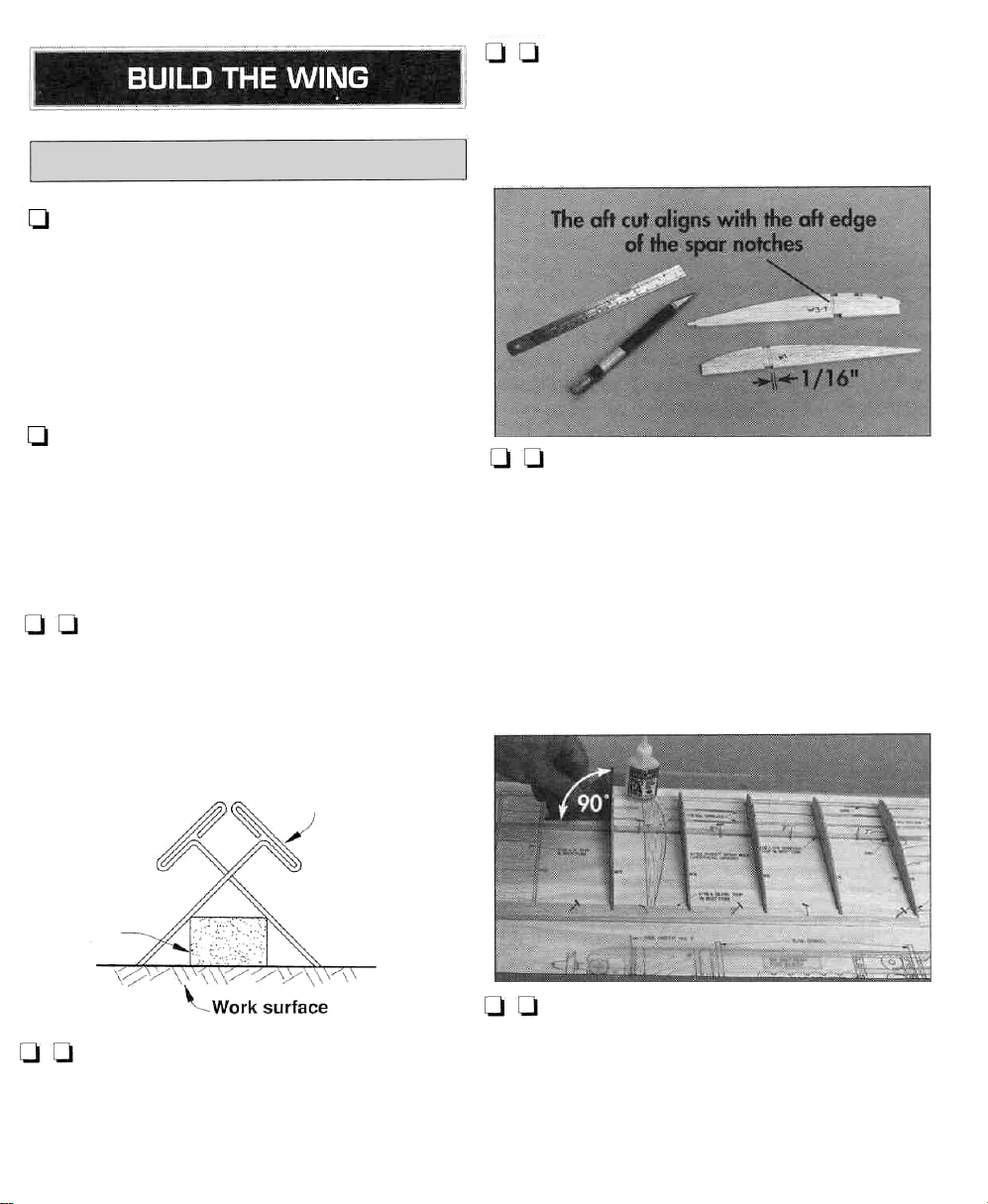
U U 4. Pin a 1/8" x 1/4" x 18-1/4" basswood
bottom spar over its location on the plan so the root
end accurately aligns with the centerline of the wing
at rib W1 on the plan. Do not insert T-pins through
the spar but install them in a "criss-cross" pattern.
Q Q 7. Test fit four W3 ribs and one W3-T rib to
the bottom spar and bottom TE over their locations
on the plan. If necessary, adjust the notches in the
ribs so they fit the spar and bottom TE. Then use a
builder's triangle to make sure the ribs are
perpendicular as you glue them in position with thin
or medium CA.
11
Page 12
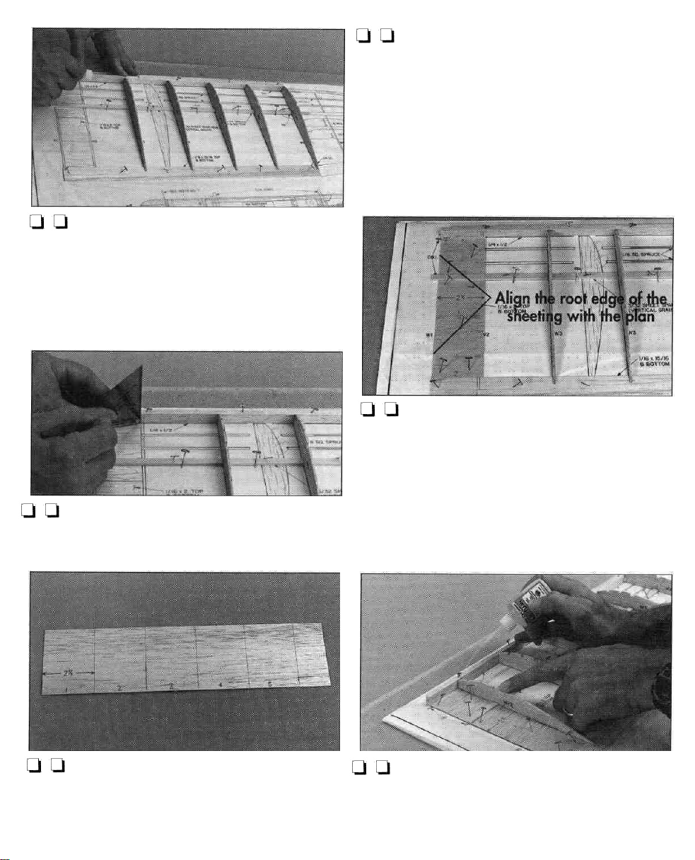
Q Q 8. Position a 1/4" x 1/2" x 18" balsa
leading edge over its location on the plan so the
root aligns with the centerline of the wing. Securely
pin the LE to the building board so it tightly contacts
the wing ribs. Then glue it in position with thin CA.
Q Q 11. Trim the 2-1/8" x 6" sheet you just made
so it fits between the bottom main spar and the
bottom trailing edge sheet. Accurately trim the root
edge of the sheet (the left edge if you are building
the right wing panel, the right edge of the sheet if
you are building the left wing panel) so it aligns with
the centerline of the wing. It's okay if the other edge
of the sheet extends past rib W2. Pin the sheet in
position but do not glue it to the wing yet.
U U 9. Mark the location of rib W2 on the leading
edge and trailing edge.
Q Q 10. Cut three 2-1/8" wide strips from the
1/16" x 3" x 30" balsa sheet. Glue two of the strips
together to make the 2-1/8" x 6" aft bottom
sheeting that fits behind the bottom spar.
Q Q 12.
fit between the leading edge and the bottom spar so the
root end accurately aligns with the wing centerline.
Note: It is important that the root edges of the
bottom sheeting accurately align with the wing
centerline because those edges will be used as a
guide to determine the position of rib W-1.
Q Q 1 3. Use the lines you marked as a guide to
glue rib W-2 in position with medium CA. Then glue
the forward and aft 1/16" bottom center section
sheeting to the spar, LE, TE and rib W-2.
12
Trim
the
third
1/16" x 2-1/8" x 3"
sheet
to
Page 13
Q Ql 14. Remove the T-pins from the bottom TE
sheeting. Then replace them in the aft end of the ribs
to hold the rear of the wing panel securely to your
building board.
1/4" BEVEL
Q Q 15. Test fit the other half of the 1/16" x
15/16"
x 36" trailing edge
sheet
that
you
cut
to
a
length of 18" in step 5. If necessary, adjust the
notches in the ribs so the aft edge of the upper TE
will align with the aft edge of the lower TE.
LJ U 16. Use a 1/8" x 1/4" x 18-1/4" basswood
spar as a guide to make a line 1 /4" from one edge
of the upper TE sheet with a ballpoint pen. See the
sketch at step 18.
BEVEL THE UPPER TE TO FIT
THE LOWER TE.
LJ LJ 18. Glue the upper TE to the bottom TE and
ribs with medium CA.
LJ LJ 19. Use a builder's triangle or square and a
ballpoint pen to mark, then cut, six 3/4" vertical-grain
shear webs from the 3/32" x 3" x 15" balsa sheet.
Q [-I 20. Test fit but do not glue the shear webs
between the ribs. If necessary, trim each shear web
so the top spar will fully seat in the notches of the
ribs and contact the tops of the webs.
LJ U 17. Use the line as a guide to bevel the aft
edge of the sheet with your bar sander and 220-grit
sandpaper.
LJ U 21. Use medium CA to glue five of the shear
webs in the center of the bottom spar between all
the ribs. You will have to temporarily remove the
T-pins, then reinsert them through the shear webs to
hold the wing to your building board.
13
Page 14

Q Q 22. Test fit, then glue/ the 1/8" x 1/4" x 18-
1 /4" basswood top spar to the ribs and shear webs
with medium CA.
LJ LJ 23. Cut a notch about 1/8" from the end of
two 1/8" x 1/8" x 16-1/2" basswood inner
turbulator spars. The notches should go halfway
through the end of the turbulator spars.
U LJ 24. Glue the turbulator spars into the ribs so the
notches at the ends of the spar extend approximately
1/32" to 1/16" past rib W2. Trim the ends of the
turbulator spars so they are even with tip rib W-3.
Q Q 26. Cut along the dotted line of the wing root
and wing tip dihedral gauge templates on the back
cover of the manual. Then glue the templates with
spray adhesive or rubber cement to a piece of balsa
wood or thin card stock (such as from a cereal box).
Use a #11 blade and a straightedge to accurately
cut the templates from the card stock along the solid
outline to make the dihedral gauges.
Q LJ 27. Test fit rib W-1 and if necessary, adjust
the notches so it fits between the top and bottom
spars. Accurately align the bottom of W-1 with the
bottom sheeting. Then use the wing root dihedral
gauge hold W-1 at the correct angle and glue it in
position with medium CA.
U LJ 25. Cut a small triangular piece from the end
of the 1/4" x 1/4" x 15" balsa stick to make a
gusset, then glue it in position with medium CA.
LJ Q 28. Remove the T-pins, then lift your wing
from your building board and peel off the wax
paper. Inspect the wing panel and add CA to glue
joints that don't look strong.
LJ Q 29. Trim, then fit, but do not glue the sixth
shear web that you already cut, between ribs W-1
and
W-2.
14
Page 15

Q Ql 30. Use your bar sander and 150-grit
sandpaper to sand the ends of the spars, bottom
sheeting/ LE and TE's so they are even with rib W1
and W3-T.
Q Q 31. Use a sharp #11 blade to remove the
portion of balsa between the lines you partially cut
on ribs W1 and W3-T.
TIP: How To Use A Razor Plane
We highly recommend a razor plane to shape the
LE's because it is the safest, fastest and most accurate
method to remove large quantities of balsa.
A. Adjust your razor plane so it removes about
1 /64" or less balsa at a time.
B. Position the LE of the wing panel at the edge of
your work bench so it is supported and the bench
does not interfere with the razor plane.
C. Hold the razor plane at an angle to the grain
direction as shown in the photo.
D. Work slowly and inspect your work frequently before you know it you will have shaved the LE
down quite far.
Q Q 32. See the "Tip" that follows. Then use a
razor plane, a hobby knife with a carving blade, or
a #11 blade to roughly carve the leading edge
according to the sketch. Note: Leave the leading
edge at least 1/16" high in front of ribs W1 and
W2 to accommodate the top sheeting. You will final
sand the LE after you join the inner panels to the
outer panels and glue the top sheeting in position.
Ul Ul 33. Use a bar sander and 220-grit sandpaper
to carefully remove any glue blobs and blend all the
ribs, spars, TE and LE.
Q 34. Arrange the plan so the left inner wing panel
is over your building board. Cover it with wax
paper. Return to step 4 and build the left inner wing
panel the same way as the right. Don't forget to
switch to the left wing panel plan so you do not
build two right panels.
15
Page 16

BUILD THE OUTER
WING PANELS
Start with the right outer wing panel so your
progress matches the photos.
Q Q 6. Position a 1/4" x 1/2" x 18" balsa
leading edge over its location on the plan so the
root aligns with the centerline at W3-T. Securely pin
the LE to the building board so it tightly contacts the
wing ribs. Then glue it in position with thin CA.
Ui l—l 1. Cover the outer panel of the right wing
plan with wax paper. Use the "crossed T-pin"
method to pin a 1/8" x 1/4" x 18-1/4" basswood
bottom spar in position so the root end aligns with
the centerline at W-3.
l-l Q 2. Accurately cut a 1/16" x 15/16" x 36"
balsa sheet to a length of 18". Pin it in position over
the plan so both ends extend past the ends of the TE
on the plan. You will sand the ends of the TE
sheeting flush with the end ribs later.
Q Ul 3. Use a straightedge and a hobby knife to cut
halfway through one W3-T rib to accommodate the
1/16" dihedral brace the same way as you did at
step 6 on page 11. Make the slot on the side of the
rib that will be visible when the rib is in position.
Ul LJ 7. Remove the T-pins from the bottom TE
sheeting. Replace them in the aft end of the ribs to
hold the rear of the wing panel securely to your
building board.
Q Q
8.
Test
fit the other half of the 1 /16" x 15/16"
x 36" trailing edge sheet. If necessary, adjust the
notches in the ribs so the aft edge of the upper TE
will align with the aft edge of the lower TE.
Q Q 9. Use a 1 /8" x 1 /4" basswood spar to mark
the guide line, then bevel the edge of the upper
TE sheet.
Q Q 10. Glue the upper TE to the bottom TE and
ribs with medium CA.
Q Q
11.
Test
fit,
then
glue,
the 1 /8" x 1
basswood top spar to the ribs with medium CA.
/4" x 18-1
/4"
Q Q 4. Test fit ribs W3-T through W9 to the bottom
spar and bottom TE over their locations on the plan.
If necessary, adjust the notches in the ribs so they fit
the spar and bottom TE.
C.] Ql 5. Set rib W3-T aside and glue all the ribs
except W3-T in position with thin or medium CA.
Use a builder's triangle to make sure the ribs are
perpendicular to the work surface as you glue them.
LJ LI 12. Cut a 1/8" x 1/8" x 36" balsa stick into
two 18" long
outer turbulator spars in the notches of ribs W4
through W9 so the ends align with W9.
16
pieces.
Test
fit,
then
glue,
the
two 18"
Page 17

Q Q 13. Fit rib W3-T to the outer panel and
accurately align it over its location on the plan. Use
the wing tip dihedral gauge to set W3-T at the correct
angle, then glue it in position with medium CA.
Q Q 14. Make a gusset from the end of the
1 /4" x 1 /4" x 15" balsa stick. Glue it with medium
CA at the position shown on the plan.
Q Q 15. Remove the T-pins. Lift your wing from
your building board and peel off the wax paper.
Inspect the wing panel and add CA to glue joints
that don't look strong.
Q Q 16. Make a 3/32" x 3/4" shear web from
the same balsa sheet you used to make the other
shear webs (originally a 3/32" x 3" x 15" sheet).
Then fit but do not glue it between ribs W3-T
and
W4.
Q Q 20. Cut the 3/4" x 12-1/4" balsa triangle
stock into two 6-1/8" pieces to make the wing tips.
Use medium CA to glue a tip to W9 so the aft edge
of the triangle wing tip aligns with the aft edge of
the
TE.
U U 21. Roughly carve the wing tip with a razor
plane or a hobby knife, then final shape the tip and
blend it to W9 with a bar sander and 150-grit
sandpaper.
Q Q 1 7. Use your bar sander and 150-grit
sandpaper to sand the ends of the spars, LE and TE's
so they are even with rib W3-T and W9.
LI Q 18. Use a sharp #11 blade to remove the
portion of balsa between the lines you cut with a
straightedge on rib W3-T.
Q Q 19. Roughly shape the LE the same way you
did for the inner wing panels.
U U 22. Use a bar sander and 220-grit sandpaper
to carefully remove any glue blobs and blend all the
ribs/ spars/ TE and LE.
Q 23. Arrange the plan so the left outer wing panel
is on your building board. Cover it with wax paper.
Return to step 1 and build the left wing panel the
same way as the right. Don't forget to switch to the
left wing panel plan so you do not build two right
panels.
17
Page 18

PREPARE THE PANELS
FOR JOINING
LJ 1. Use your razor plane or a hobby knife to
shave the sharp corners of the leading edge of one
of the wing panels. Round and final shape the
leading edge with a bar sander and 150-grit
sandpaper according to the cross section on the
right wing panel drawing on the plan. Shape the
remaining wing panels the same way.
Note: The Piece 0' Cake is a motor glider, not a
high performance acrobatic model - it's named the
"Piece 0' Cake" after all! It is not critical that you
shape the leading edges with the greatest precision.
You probably would not notice a difference in the
flight performance of a Piece 0' Cake with an
accurately finished leading edge and a Piece 0'
Cake with a leading edge roughly carved to shape
with a hobby carving knife. This isn't to say that you
should not always strive for building accuracy and a
good finish, but don't worry if your LE's don't look
perfect. Building a straight fuselage and flat, warp
free wings are areas where you should concentrate
most of your building efforts.
U2. Use a sanding block or your 5-1/2" bar
sander and 220-grit sandpaper on all four wing
panels to remove any glue blobs and blend all the
ribs to the spars/ LE and TE.
JOIN THE INNER WING PANELS
to decrease the height of the dihedral brace if needed
so it fits between the top and bottom spar.
Q
2.
Test
fit
the
dihedral brace in the
panel. Without using any glue, join the panels with
the dihedral brace and the shear webs you cut
earlier, then temporarily clamp them together with
C-clamps, spring clips or clothespins. Make sure the
tops of ribs W1 and the bottom sheeting of both
wing panels align.
01 3. Test fit a 1/16" die-cut plywood forward
dihedral brace DB1-B between the W1 ribs and the
leading edges. The top of DB1-B should be 1/16"
below the LE's to accommodate the 1/16" top center
section wing sheeting that will be added later.
Q 4. After making any adjustments required so the
wing panels fit together and align, separate the wing
panels. Remove the dihedral braces and the shear
webs.
other
wing
LJ
1.
Test
fit a
1/16"
die-cut
brace DB1-A in the left wing panel. Use a bar sander
plywood
center
dihedral
U 5. Gather a stack of books, balsa blocks or
something similar to prop up the end of one of the
wing panels 3-1/2".
LJ 6. Lay a piece of wax paper on your building
table. Mix a batch of 30-minute epoxy. Coat all the
joining surfaces with 30-minute epoxy, then join the
inner wing panels with the dihedral braces and
install the balsa shear webs. Place the wing on the
wax paper on your building table. Immediately
proceed to the next step.
18
Page 19

LJ 7. Clamp the wing halves together. Then prop up
one of the tips so it is 3-1/2" above your table.
Q Q 4. Clamp the wing halves together. Then prop
up the tip so it is 3-1 /2" above your table.
1 8. Wipe away excess epoxy before it cures and do
not disturb the wing panel until the epoxy if fully cured.
JOIN THE OUTER AND INNER
WINGPANELS
Q Q
1.
Test
fit the left outer
inner panel with DB1-A , DB-2 and the shear webs.
If needed, adjust the dihedral brace so they fit.
Temporarily clamp the panels together with C-
clamps, spring clips or clothespins and make sure
ribs W3-T align.
Q Q 2. After making any adjustments required so
the wing panels fit together and align, separate the
wing panels and remove the dihedral brace and the
shear webs.
U U 3. Lay a piece of wax paper on your building
table. Mix a batch of 30-minute epoxy. Coat all the
joining surfaces with 30-minute epoxy, then join the
wing panels with the dihedral brace and install the
balsa shear webs.
wing
panel
to the left
Q Q 5. Wipe away excess epoxy before it cures
and do not disturb the wing panel until the epoxy is
fully cured.
Q 6. Return to step 1 and join the panels of the
other wing half the same way.
FINISH THE WING
Q 1. Final-sand the wings with your bar sander and
320-grit sandpaper and blend the LE's where they
meet at each panel joint.
Q 2. Use the remainder of the 1/16" x 3" x 30"
balsa sheet you used to sheet the bottom center
section of the inner panels to sheet the top center
section of the inner panels.
d 3. Use your bar sander and 220-grit sandpaper
to blend the top and bottom center section to the rest
of the wing.
19
Page 20

LJ 4. Use your bar sander to bevel the top edges of
the die-cut plywood wing protectors. Glue the wing
protectors to the top of the trailing edge of the wing
with medium CA so the inner edges are 3/4" from
the centerline of the wing.
Q 4. Remove the T-pins, then lift F2 from the plan
and peel off the wax paper. Reinforce the glue joints
in the corners with medium CA.
Q 5. Build F3 and F4 from the 1/8" x 1/4" x 24"
balsa stick the same way you built F2.
BUILD THE FORMERS
I—I 1. Arrange the plan so the fuselage drawing is
over your building board. Then cover the drawings
of F2,F3 and F4 with wax paper.
Q 2. Make the two vertical side pieces of F2 from the
1/4" x 1/4" x 15" balsa stick you used for the wing
gussets. Pin them in position over the plan.
LJ 3. Cut the horizontal pieces or F-2 from the same
balsa stick. Glue them in position with thin CA.
PREPARE THE FUSE SIDES
LJ 1. Remove the 3/32" die-cut balsa fuselage
sides from their die sheets. Temporarily pin them
together and use your bar sander and 150-grit
sandpaper to remove slivers or die-cutting
irregularities, and make sure the sides are identical.
LJ 2. Separate the fuse sides, then lay them on your
work bench as a mirror image and mark one as the
right inside and the other as the left inside.
20
Page 21

Q 3. Use a sharp hobby knife and a straightedge to
cut 1 /8" off the front of only the right fuselage side.
CJ 4. Push a large T-pin through the punch marks that
are on the outside of the right fuselage side to transfer
the punch marks to the inside. Use a straightedge to
draw a line with a ballpoint pen connecting the punch
marks that indicate where the formers are located on
the inside of both fuselage sides.
U 6. Glue a 1/4" x 30" balsa triangle stick to the
inside right fuselage side top as shown on the plan.
Note that the stick "ends" approximately 2-1/4"
from the back of the fuselage and you will have to
cut the stick into two pieces at the front of F3. Do not
glue a triangle piece to the fuselage side at the top
of the hatch compartment until instructed to do so.
LI 7. Glue a 1 /4" x 30" balsa triangle stick to the
bottom inside of the right fuselage side as shown on
the plan. The front of the stringer extends all the way
to the front of the fuselage and like the top triangle
stick, is cut into two pieces at the front of F3 and ends
approximately 2-1/4" from the back of the fuselage.
Q 5. Make two 2-1/2" long servo rail supports
from the remainder of the 1/8" x 1/4" balsa stick
you used to make fuselage formers F3 and F4. Glue
the supports to the inside of both fuselage sides in
the location shown on the plan and in the photo.
Q 8. Glue two more 1/4" x 30" balsa triangle
sticks to the inside of the left fuselage the same way
as the right.
JOIN THE FUSELAGE SIDES
Q 1. Test fit but, do not glue, all three formers to the
right, then the left fuselage side. If necessary, adjust the
45 degree angle on the corner of each former so the
sides of the formers fully contact the fuselage sides.
21
Page 22

LI 2. Position former F2 on the right fuselage side so
the aft edge aligns with the guideline you made. Use
a builder's triangle to hold the former perpendicular
to the fuse side. Glue it in position with thin CA.
Q 3. Glue former F3 to the right fuselage side the
same way.
D 4. Without using any glue, join the left fuselage
side to the right fuselage side. Then place the
assembly over the top view of the fuselage plan.
Q 5. Align F2 and F3 and the fuselage sides
between F2 and F3 with the plan. Align F2 and F3
with the guide lines on the left fuselage side, then
hold the fuselage to the plan so the sides are
parallel. Check and double check that everything
aligns. Finally, use thin CA to tack glue the formers
to the left fuselage side.
Q 6. Inspect the fit and alignment of the fuselage
sides and the formers, then securely glue the formers
to the fuselage sides with medium CA.
Q 8. Accurately align F4 with the guidelines you
drew and align the top and bottom of the aft
fuselage sides. Glue F4 in position with thin CA.
Q 9. Remove the rubber bands. Temporarily clamp
the ends of the fuselage together with a piece of
1 /8" x 1 /4" balsa to simulate the spacing of the fin
TE. If necessary, trim the triangle sticks at the aft
ends so they do not interfere.
LI 10. Position the 1/8" x 1/4" balsa spacer and
the clamp so the top of the fuselage aft of F3 will
fully contact the plan. Align the top of the fuselage
sides aft of F3 with the plan, then pin the fuselage
sides to your building board over the plan.
Ql 7. Position former F4 between the fuselage sides.
Hold the rear of the fuselage sides together with a
few small rubber bands.
Q 11. Use a builder's triangle to align the front of
the fuselage over the plan, then use thick balsa
blocks (you may use the cowl blocks) pinned to the
building board to hold the front of the fuselage in
alignment over the plan.
22
Page 23

U 12. Use your bar sander and 150-grit sandpaper
to sand the bottom of the fuselage sides aft of F3 so
the formers and fuselage sides are even. Make sure
the clamp and the 1/8" x 1/4" spacer in the back
of the fuselage sides will not interfere with the
bottom sheeting (we had to replace the paper clamp
shown in previous photos with a clothespin and
shorten the balsa spacer).
SHEET THE BOTTOM OF
THE FUSELAGE
Q
1.
Test
fit,
then glue the
balsa sheet to the bottom of the fuselage so the front
edge "ends" in the middle of F3.
1/16" x 2-1/4" x 20"
U 4. Use the mark as a guide to cut the angle for the
right thrust at the front of the fuse bottom with a
straightedge and a hobby knife. Test fit, then use
medium CA to glue the forward fuse bottom in position.
Q 5. Use your bar sander with 150-grit sandpaper
to sand the edges of the forward fuse bottom so they
are even with the fuselage sides.
INSTALL THE FIREVVALL
U 2. Remove the T-pins, then lift the fuselage from the
plan. Reinforce the joint between the aft fuse bottom
and the triangle stock from inside the fuselage with
thin CA. Use a hobby knife, then your bar sander with
150-grit sandpaper, to trim the excess bottom sheeting
so it is flush with the fuselage sides.
Q 3. Position the 1/16" x 2-1/4" x 11-1/4"
plywood forward fuselage bottom on the fuselage.
Mark the front of the right fuselage side on the fuse
bottom.
Q 1. Cut two of the remaining pieces of 1 /4" triangle
stock to the correct length. Glue them to the top of the
hatch area in the front of both fuselage sides.
Q 2. Cut, then glue the remaining pieces of 1/4"
balsa triangle stock to the sides, then to the bottom
of the front of the fuselage.
Q 3. Glue the die-cut 1/16" plywood H1 forward
hatch compartment top in position. Cut and glue the
last piece of 1/4" triangle stock underneath it. The
top and bottom triangle pieces are a little difficult to
make fit perfectly because of the "double taper"
required in the comers, but don't worry - most of
the strength is gained along the sides of the triangle
pieces.(See the photo that follows.)
23
Page 24

LJ 4. Use a large sanding block and 150-grit
sandpaper to sand the triangle pieces, fuselage
sides, fuselage top and fuselage bottom so they are
all flat and even.
Q 5. Glue the 1/8" plywood firewall F1 to the front
of the fuselage with 30-minute epoxy. Use masking
tape to securely hold the firewall to the front of the
fuselage until the epoxy fully cures.
LJ 6. Use your bar sander and 150-grit sandpaper
to sand the edges of the firewall flush with the
fuselage sides, top and bottom.
Q 1. Use the 1/8" x 3/8" x 12" plywood stick to
make two servo rails that rest upon the servo rail
supports between the fuselage sides. Fit but do not
glue the servo rails in position, then place your
servos on the rails.
Q 2. Place servo wheels or short servo arms on
your servos, then position the servos so the arms or
wheels will not interfere. Adjust the servo rails so
they are parallel and allow enough space for you to
remove the servos. Carefully (without gluing the
servos to the rails) glue the rails to the rail supports
with medium CA.
Q 3. Remove the servos, then securely glue the rails
to the rail supports and the fuselage sides with
additional medium CA.
Reinstall
the
servos,
then
drill
1/16" holes through the rails and mount the servos
with the wood screws included with your radio.
Q 4. From the remaining piece of the 1 /4" x 1 /4"
balsa stick, make a forward and an aft pushrod
guide tube support to fit between the fuselage sides
in the location shown on the plan. Test fit the
supports to make sure they are the correct length.
FRONT GUIDE
TUBE SUPPORT
2-1/16"
AFT GUIDE
TUBE SUPPORT
1-7/16"
INSTALL THE SERVOS &
PUSHROD GUIDES
Refer to this photo for the following three steps.
TO MATCH
SERVO WHEELS
MAKE FROM 1/4"
DRILL TWO 9/64"
EVENLY SPACED.
X 1/4" BALSA.
HOLES
Q 5. Drill 9/64" holes through the supports in the
locations shown in the sketch. The holes in the front
support should match the spacing of the holes you will
connect your pushrods to in your servo wheels. If you
do not have a 9/64" drill bit, you may use a 1/8"
drill instead, but insert one of the outer guide tubes in
the holes and spin it around to enlarge the hole so the
guide tubes can slide through a little easier.
24
3/8"
Page 25

LJ 6. Reinstall, but do not glue, the guide supports in
the fuselage, then cut the 36" outer guide tubes into
two 23" long pieces. Roughen the outside of the guide
tubes with 150-grit sandpaper so glue will stick. Then
slide them through the slots in the back of the fuselage
and route them through the guide supports.
U 8. Position the aft support so the guide tubes
make a smooth transition from the slots at the back
of the fuselage to the front support. Glue it to the
fuselage sides and F4 with thin CA.
SCREW-LOCK
CONNECTOR
POSITION THE FRONT GUIDE TUBE
SUPPORT SO THE PUSHROD WIRES
ALIGN WITH THE SCREW-LOCK
PUSHROD CONNECTORS.
4-40x1/8" Cap Screw
Pushrod Connector
Servo Arm
Nylon Retainer
PUSHROD
PUSHROD WIRE
Pushrod
U 7. due the guide tubes to the slots in the back of
the fuselage with microballoons and epoxy.
Microballoons are a powder that you can mix with
epoxy to make a sandable filler where a bond is
required. If you do not have microballoons, glue the
tubes to the fuselage sides with medium CA, then fill
the rest of the slot with HobbyLite filler.
LJ 10. Use your bar sander and 80-grit sandpaper
to sand the guide tubes and filler flush with the
fuselage sides.
Q 7. Insert a Screw-Lock Pushrod Connector in both
servo wheels. Slide the 1/16" x 36" pushrod wires
included with this kit through the guide tubes and
accurately align the front support so the wires pass
through the pushrod connectors. Use thin CA to glue
the front support to the fuselage sides.
U 11. Glue the pushrod guide tubes to the supports
with medium CA.
SHEET THE TOP OF THE FUSE
CJ 1. Use your bar sander and 80-grit sandpaper to
sand the tops of the fuselage sides and the tops of
the formers so they are even. Clip clothespins to the
top of the fuselage sides in the wing saddle area,
then place a long straightedge such as a metal ruler
on the saddle leaning against the clothespins.
25
Page 26

Q 2. Place the stab on the back of the fuselage with
a small weight on top of the middle of the stab.
Stand back from the fuselage and view the
straightedge and the stab. If necessary, use your bar
sander with 80-grit sandpaper to carefully sand the
tops of the fuselage sides until the stab aligns with
the straightedge.
Q 5. With the stab in position on the fuselage, use a
ballpoint pen to mark the location of the leading
edge of the stab on the top of the fuselage sides. This
indicates where the top fuselage sheeting "ends."
U 6. Sheet the top of the fuselage with the
1/16" x 3" x 12" balsa sheet between F3 and the
marks indicating the LE of the stab. Apply the
sheeting in "planks" running cross-grain as shown
on the fuselage plan.
U 3. Mark the top of the fuse sides 1/4" from the
end. Use the marks as a guide to cut a notch for the
leading edge of the elevator.
LJ 4. Place the stab and elevator on the fuselage so
the aft edge of the elevator leading edge is 5/16" in
front of the aft end of the fuse. Move the elevator up
and down to adjust the notch if the fuselage
interferes with the elevator LE.
U 7. Use your bar sander and 150-grit sandpaper
to sand the edges of the fuselage top even with the
fuselage sides.
LJ 8. Use medium CA to glue the die-cut 1/16"
plywood H4 aft hatch compartment top to the
26
Page 27

fuselage. Then glue the 1/16" die-cut plywood H3
hatch ledge to the bottom of the aft hatch
compartment top so 3/8" protrudes in front of H4.
Glue a piece of 1/16" leftover plywood to the
bottom of the ledge for the hatch screw.
l-l 9. Trim the 1/16" plywood hatch to it fits
between the front and aft hatch compartment tops.
Don't make it fit too tight; leave a little space for the
iron-on covering.
Q 10. Glue the plywood H2 hatch tab to the bottom
of the hatch so only 1/8" of the tab protrudes past
the front of the hatch. Fit the hatch to the
compartment, then drill a 1/16" hole through the
hatch and the ledge.
when positioned on the fuselage. Use medium CA to
glue the windshield in position. Then sand the edges
flush with the fuselage.
1/8"
FUSELAGE
BOTTOM
1/8"
Q 11. Remove the hatch and enlarge the hole in the
hatch only with a 3/32" drill bit. Reinstall the hatch,
then secure it to the fuselage with a #2 x 3/8" screw.
Sand the edges of the hatch even with the fuse sides.
Q 12. Trim the front of the 9/16" x 2-1/4" balsa
windshield so it does not interfere with the hatch
3-7/8"
3/32"
Q 1. Drill 3/32" holes for the landing gear in the
fuse bottom where shown in the sketch. Bevel the
inner edges of the holes on the fuse bottom so the
landing gear will rest flush.
1—1 2. Cut two 2-1/4" landing gear rails from the
remainder of the 1/8" x 3/8" plywood stick you
used for the servo rails. Fit the landing gear in the
fuselage, then use medium CA to glue the rails to the
fuse bottom behind and in front of the landing gear.
(See the following photo.)
27
Page 28

LJ 3. Use your bar sander with 80-grit sandpaper to
sand the ends of the landing gear rails so they are
flush with the fuselage sides. Bevel the corners for a
neater appearance.
LJ 4. Center the 1/16" plywood landing gear plate
on the landing gear rails. Drill four 1/16" holes
evenly spaced 1/4" from both ends of the plate.
Remove the plate, then enlarge the holes in the plate
only with a 3/32" drill bit.
MOUNT YOUR ENGINE
U 1. Center your engine on the firewall, then mark
the location of the mounting holes. Drill 1/16" holes
at the marks and temporarily mount your engine
with #2 x 3/8" screws (not included).
U 2. Glue both 3/8" x 2" x 1-7/8" cowl side
blocks to the firewall with medium CA.
Q 5. Temporarily mount the landing gear in the
fuselage with the landing gear plate and four #2 x
3/8" screws.
LJ 6. Make four 1/4" x 5/8" landing gear bearing
plates from leftover 1/16" plywood. Use medium
CA to glue them to the fuselage sides next to the
landing gear. Make sure the landing gear is straight
and perpendicular to the fuse bottom.
Q
3.
Test
fit and shape a 3/8" x 1-1/2" x 1-3/4"
cowl bottom block so it fits between the side blocks
on the bottom of the fuselage. Lightly push the
bottom block into the bottom vent tube on the engine
so the tube leaves a mark on the block, then drill a
3/16" hole through the block at the mark. Glue the
block in position with medium CA.
28
Page 29

Q 4. Remove the engine (so it does not get balsa
dust in it), then sand the cowl blocks so they are flush
with the fuselage. Round the front edges of the cowl
blocks for a finished appearance. Start with your
bar sander and 80-grit sandpaper, then finish by
hand-sanding with 320-grit sandpaper. Reinstall
your engine just to see how it looks!
3/8"
5/16"
5/16"
1/8"
F-3
Q 5. Drill 3/16" holes in the fuselage sides at the
locations shown in the sketch for the wing dowels.
Cut the 6-1/2" dowel in half. Use sandpaper to
chamfer the ends of the wing dowels, then test fit
them in the fuselage, but do not glue the dowels in
place until instructed to do so.
U 2. Accurately mark the center of the fuselage top
sheeting at the front over F3 and at the rear. Position
a straightedge on the fuse top and align it with the
centerlines you marked. Then place the stab on the
fuselage and align the centerline of the stab with the
straightedge. Temporarily attach the stab to the
fuselage with T-pins.
Q 1. Remove the elevator from the stab, then mark
the center of the stab. Use a builder's triangle to
mark a centerline on the top of the stab at the mark.
U 3. Carefully turn the fuselage over and lightly
mark the outline of the fuselage sides on the bottom
of the stab. This line indicates where to apply the
covering "up to" and apply glue when it is time to
glue the stab to the fuse.
29
Page 30

Q 4. Align your straightedge with the marks on the
fuse top again, then lightly mark a 1" long centerline
on the fuse top in front of the LE of the stab.
ALIGN THE FIN
Q 1. Position the fin on the stab with the trailing
edge of the fin between the fuse sides.
Q 2. Cut the 3/16" x 3/16" x 6" balsa stick into
two 2-1/2" long pieces. Use your hobby knife to
carve them into triangle pieces (like the 1/4"
triangle stock used in the fuselage), then round the
ends. These are the fin braces.
Q 5. Align the fin with the centerline you marked on
the top of the fuselage, then pin the front of the fin to
the fuse sheeting with one small T-pin. Lightly trace
the outline of the fin on the fuse top and the outline
of the fin and triangle fin braces onto the stab, and
trace the outline of the fin braces onto the fin. These
lines will be guide lines for covering so you can glue
the fin and triangle pieces to bare balsa after you
cover them.
d 6. Cut the notch in the fin the same as you did on
the fuselage to allow the elevator to move up
and down.
Q 3. Temporarily place the fin braces on the fin and
the stab.
LJ 4. Use medium CA to glue a piece of leftover
1/16" balsa to the bottom of the fin in front of the
stab to fill the space.
PREPARE THE MODEL
FOR COVERING
Q 1. Remove the fin and stab from the fuselage.
Inspect the wing, fuselage, and tail surfaces for glue
joints that don't look strong and reinforce them with
thin or medium CA.
30
Page 31

U
2.
Test
fit
the
wing
on the fuselage.
knife and a bar sander with 150-grit sandpaper to
shape the top of F2 and the windshield so the wing fits.
Q 3. Remove the engine, pushrods, landing gear,
hatch, wing dowels and any other hardware that
may interfere with covering.
Use a hobby
does not pull on the airframe as much as MonoKote
film. Therefore, EconoKote film is ideal for lighter
weight structures like your Piece 0' Cake, especially
the tail surfaces.
If this is the first time you have covered a model
refrain from attempting a complicated trim scheme.
Add stripes, graphics, and various designs to your
Piece 0' Cake cut from different colors of EconoKote
film, then iron them directly over the base color.
Self-adhesive trim sheets may also be used. Try only
a single color base (usually a lighter color such as
white or yellow) with perhaps a single stripe, your
AMA number, or even some stick-on graphics. A
simple trim scheme will get you in the air faster and
look much better than a model that was difficult to
cover because of a complicated trim scheme.
U 4. Fill dents, scratches and glue joints on the
surface of the model that may show through the
covering with HobbyLite filler. Slightly round the
top and bottom corners of the fuselage and the
windshield with your bar sander and 220-grit
sandpaper, then sand the fuselage so it is smooth
and even.
COVERING TIPS
We recommend you cover your Piece 0' Cake with
Top Flite EconoKote® iron-on model covering film.
EconoKote film is similar to famous Top Flite
MonoKote® covering film except that EconoKote film
is lighter weight, requires less heat to apply and
HOW TO COVER YOUR MODEL
We will use the stabilizer as an example because
the techniques shown apply to the rest of the
Piece 0'Cake.
Q 1. Here is a "rule of thumb" to keep in mind before
you begin: Where possible, apply the covering so all
seams face downward or rearward. You can do this by
covering the bottom (of the wing, fuse, stab, etc.) first.
Never cut the covering after you iron it to the
wood except near the tips. Modelers who do this
may weaken the structure which could cause it to
fail during flight.
31
Page 32

U 2. Cut the covering for one half of the bottom of
the stab so it is approximately 2" oversize. Use a
straightedge to cut the end that aligns with the lines
you drew that indicate the fuselage. Use a Top Flite
MonoKote Iron with a Hot Sock to securely bond the
covering to the perimeter (LE, TE, tip, middle) of
the stab.
Ll 4. Seal the front, rear and tip of the covering to
the stab. Then heat the covering as you pull and
stretch it around the tip. It takes a little practice to get
all the wrinkles out so don't be discouraged if it
doesn't look perfect on your first attempt (or the
second or third time). You can reheat and stretch the
covering many times. It helps to place the stab on
your work bench or a stand so the tip is over the
edge, and place a weight on top of the stab to hold
it down. This will allow you to pull the covering with
one hand and hold the iron in your other hand.
Q 3. Place the stab right side up on your building
table (preferably on a cutting mat if you have one)
and use a straightedge to trim the covering about
3/32" from the LE, TE and tip, but leave a "handle"
at the corner so you can stretch the covering around
the tip as you heat it.
LJ 5. Cut the excess covering from the tip with a
single-edge razor blade or a sharp hobby knife.
32
Page 33

Ul 6. Cover the other bottom stab half the same way.
LJ 10. Cover the triangular fin reinforcements. Trim
the excess so it "overhangs" the edges by
approximately
way all you have to do is glue the fin reinforcements
to the fin and stab and seal the edges with the iron.
3/32".
Don't
iron
it
down
yet.
This
CJ 7. Cut the covering for one half of the top of the
stab so it is approximately 2" oversize. Before you
iron it down, trim the covering so it aligns with the
lines you marked indicating the fin and triangle fin
reinforcement. This will allow you to glue the fin
reinforcements directly to the bare wood and avoid
cutting the covering directly on the wood after you
iron it down.
LJ 8. Iron the piece of covering you just "custom cut"
to the top of the stab. Then make the other side the
same way and iron it in position.
U 11. Use the same methods described above
to cover the rest of the model using the correct
Covering Sequence.
COVERING SEQUENCE
Tail Surfaces:
1. Elevator bottoms, then tops
2. Fin right, then left
3. Rudder right, then left
Fuselage:
1. 1 /8" Plywood landing gear mounts on the bottom
of the fuselage
2. Bottom behind the landing gear mounts, then in
front of the landing gear mounts
3. One side, then the other
4. Top forward, then aft of the wing saddle
5. Front windscreen area
6. Hatch
7. Landing gear plate (or you could paint it instead)
Q 9. Align the elevator with the stab, then transfer
the hinge slots from the elevator (since they are
visible and you have not yet covered over them) to
the stab by marking them on the covering with a
felt-tip pen.
Wings;
1. Tips
2. Bottom inner panels
3. Bottom outer panels
4. Top inner panels
5. Top outer panels
33
Page 34

SHAPE THE FLYING SURFACES
Q 1. Due to the lightweight structure of the Piece 0'
Cake and the shrinkage of the covering, the wing,
fin, rudder, elevator and stab can warp or twist.
Correct the twists by carefully twisting the part in the
opposite direction of the built-in twist, then heat the
covering with your iron or heat gun until the twist is
removed and the part is flat.
Add "washout" to the wing tips. Washout is where
the trailing edge of the wing at the tip is twisted
upward. This gives the wing tip a lower angle of
attack than the rest of the wing and will reduce the
tendency for the wing to "tip stall."
JOIN THE TAIL SURFACES TO
THE FUSELAGE
LJ
1.
Test
fit the stabilizer and fin to the
make sure none of the covering interferes with the
glue joints and areas that are exposed balsa.
LJ 2. Apply a film of 30-minute epoxy to the
exposed balsa on the bottom of the stab and the
stab saddle area of the aft fuse. Then position the
stab on the fuse. Use the centerlines on the top of the
stab and fuse, and the exposed balsa on the bottom
of the stab, as a guide to align the stab with the fuse.
Use T-pins, weights or clamps to hold the stab to the
fuse until the epoxy fully cures. Use a cloth
dampened with alcohol to wipe away excess epoxy
before it cures.
fuselage
to
LJ 2. Lay the outer panel of the right wing on your
building table. Place a 1/4" piece of balsa under
the wing tip at the trailing edge. Heat the covering
until the wrinkles disappear and the wing will stay
twisted without the shim. You may have to heat the
bottom of the outer wing panel too.
Q 3. Add washout to the left outer panel the same
way. Make sure the inner wing panels are flat and
warp free as described in step 1.
LJ 3. Use epoxy to glue the fin to the stab and fuse.
While you align the fin, use a builder's triangle to
make sure the fin is perpendicular. Use T-pins to hold
the fin in position until the epoxy fully cures. Some
modelers may prefer to glue the fin in position with
medium CA and this is acceptable as long as you
can achieve proper alignment before the CA cures.
CJ 4. Test fit the fin reinforcements to the fin and
stab/ then glue them in position with medium CA.
34
Page 35

Q 5. Use a Trim Seal Tool or a MonoKote Iron
to seal the perimeter of the covering on the
reinforcements to the fin and stab.
the center of the hinge, then join the surfaces and
remove the pins.
Q 3. Confirm that the ends of the elevator align with
the ends of the stab, that the hinges are centered,
and there is a small gap between the stab and
elevator (just enough to see light). A small gap is
desirable so you do not inadvertently glue the
elevator to the stab.
Q 6. If necessary, cut 1/4" strips of covering and
use your Trim Seal Tool to iron the strips in the
"corners" where the bottom of the stab meets the
fuse and the fin meets the top of the fuse.
HINGE THE CONTROL
SURFACES
Make sure you join the elevator to the stab first,
then join the rudder to the fin.
CUT THE COVERING
AWAY FROM THE SLOT
LJ 1. Use your hobby knife and a sharp #11 blade
to remove a small strip of covering from the hinge
slots to expose them.
TEMPORARY PIN
TO KEEP HINGE
CENTERED
0 2. Join the elevator to the stab with the hinges. If
the hinges will not stay centered, stick a pin through
Q 4. Carefully apply 4-6 drops of thin CA to both
sides of the hinges. Keep a cloth handy to wipe
away excess CA. If you spill a few drops of CA
on the covering, you can use CA Debonder
(GPMR6039) to remove it, or carefully peel it off
with a hobby knife after it fully cures.
Do not use accelerator on any of the hinges. Do not
glue the hinges with anything other than thin CA
and do not attempt to glue one half of the hinge at
a time with medium or thick CA. They will not be
secure and the controls could separate while the
model is flying.
Q 5. Let the CA fully cure, then carefully flex the
elevator several times to check the movement.
Q 6. Hinge the rudder the same way as the stab.
FUELPROOFING
Use 30-minute epoxy thinned with alcohol or
fuelproof model airplane paint to coat areas that
may be exposed to raw fuel or exhaust residue.
These areas include the firewall, inside the cowl
sides and bottom, the underside of the hatch, the
landing gear plate (if you did not cover it with
iron-on film), and inside the fuselage around the
wing saddle area.
35
Page 36

CONNECT THE SERVOS
I,.) 1. Use "Z-Bend" pliers or read the following
procedure to make a "Z-bend" in the end of one of
the 1/16" x 36" pushrod wires.
How To Make A Z-Bend In A Pushrod Wire With
Regular Pliers
A. Make a sharp "L-Bend" 1/8" from the end of
the wire.
B. Grip the first bend in your piiers and make another
90 degree bend in the wire 1 /8" behind the first.
C. Hold the "bends" in the pliers, then make a third
bend aligning the first two bends to make the
Z-bend.
Q 2. Use a new #11 blade to cut the covering from the
pushrod guide tube exits in the rear of the fuselage,
then temporarily mount a Screw-Lock Pushrod
Connector to the rudder servo wheel. Slide the pushrod
wire with the Z-bend into the pushrod guide tube
through the back of the fuselage and into the pushrod
connector on the elevator servo. Connect a small
control horn to the pushrod wire.
36
Page 37

RIGHT WRONG
LJ 3. Position the control horn on the right side of
the rudder so the holes in the control horn align with
the hinge gap.
LJ 7. Mount the engine to the firewall.
Q 8. Mount the landing gear in the fuselage with the
mount plate and four #2 x 3/8" screws, then mount a
1-1/2" wheel with a 3/32" wheel collar (not
included, GPMQ4302) on each landing gear wire.
I—I 9. Use a sharp hobby knife to lightly cut a small
strip of covering from the bottom of the fuselage
where the die-cut 1/16" plywood tail skid is to be
located. In the Covering section of the manual we
discourage the practice of cutting the covering directly
on the balsa, but it is okay to do for the tail skid since
it is not structural. If you haven't already done so,
cover the skid with the same iron-on film you used for
the rest of the model, or just pant it. Use medium CA
to glue the tail skid to the bottom of the fuselage.
Q 4. Use the holes in the base of the control horn as
a guide to drill two 1/16" holes through the rudder,
then mount the control horn with two 2-56 x 3/8"
screws and the nylon control horn plate.
d 5. Make a Z-bend in the other pushrod and
connect the elevator servo to the elevator with the
pushrod connector and a control horn the same way
you did the rudder.
Q 6. Cut the wires so they protrude from the pushrod
connector by 3/8".
FINISH INSTALLING THE RADIO
U 1. Wrap your battery pack in 1 /4" foam rubber,
then mount it in the fuselage in the location shown
on the plan. Be certain the #2 x 3/8" screws that
37
Page 38

mount the engine to the firewall (and protrude from
the back of the firewall) will not contact the battery
pack. If the screws wear through the battery casing
they could cause a short circuit and start a fire. To
protect the battery pack, place a 1/8" piece of balsa
between your battery pack and the firewall.
Note: Only a 500 mAh "square pack" (or smaller
unit ) will fit in the battery compartment of the Piece
0' Cake. You can purchase a square battery pack
separately if you do not have one. Some hobby
shops or electronics shops will convert a flat pack
into a square pack.
Lay another piece of foam on top of the receiver, then
glue a 1 /8" piece of leftover plywood or balsa to the
fuselage sides on top of the receiver to hold it securely
in position.
Ul 4. Mount the on/off switch in a location that will
not interfere with the receiver or pushrods and will
not become coated with exhaust residue.
CUT
CUT
LI 2. Place a piece of 1/4" foam rubber large
enough to cushion the bottom and sides of your
receiver in the bottom of the fuselage just behind the
servos. Place your receiver in the foam. You may
have to flex the pushrods to the side to slip your
receiver past them.
0 3. Plug the servos and the switch into the receiver.
The Piece 0' Cake is a two channel model (where the
turning function is the rudder, not ailerons) so connect
the rudder servo into channel 1 (or the aileron
channel) of your receiver.
RUBBER
BAND
STRAIN RELIEF
INSIDE FUSELAGE
ANTENNA HOLDER
AT
THE TOP OF THE
VERTICAL STABILIZER
Q 5. Make a strain relief and an antenna hook
from a cut off servo arm as shown in the sketch.
Place the strain relief on the antenna about 3" from
the receiver. Mount the antenna to the antenna hook
and a T-pin inserted into the leading edge of the fin
as shown in the photo and the sketch. Never shorten
the antenna wire but let the excess wire "dangle"
past the antenna hook.
38
T-PIN
Page 39

U 6. Confirm that the battery pack and the receiver
are adequately cushioned on all sides and securely
mounted so they will not become dislodged during
flight or a rough landing.
Q 7. Cut a hole in the covering over the wing dowel
holes in the fuselage, then install the dowels. Glue
the dowels in position with medium CA, then coat
the ends with epoxy or fuelproof paint.
Q 8. Apply 1/16" thick Great Planes Single-Sided
Foam Tape (GPMQ4422) to the wing saddle of
the fuselage.
nose. Use
(GPMQ4485). Our prototype Piece 0' Cake
required 6 oz. of Great Planes stick-on lead weight
in
the battery compartment to balance.
Great Planes Adhesive Lead Weights
SET THE CONTROL THROWS
BALANCE YOUR MODEL
This section is important and must NOT be omitted.
A model that is not properly balanced will be
unstable and possibly unflyable.
1—1 1. Accurately mark the balance point on the
bottom of the wing near the fuselage sides with tape
or a felt-tip pen. The balance point is shown on the
plan and is 2-15/16" (75mm) aft of the leading
edge.
U 2. Place the wing on the fuselage, then hold it in
place with two or four #64 rubber bands. When it is
time to fly your Piece 0' Cake, you should secure the
wing with six rubber bands, crossing the last
2-15/16"
two.
U 1. Center the servos before you measure the
control throws. Temporarily remove the servo wheels
from the servos, then turn on your transmitter and
receiver. Set the trims on the transmitter to neutral,
then reinstall the servo wheels on the servos.
Q 2. With the transmitter and receiver still on,
neutralize the elevator and rudder on the model,
then secure the pushrods to the Screw-Lock Pushrod
Connectors with the 4-40 x 1 /8 screw and a drop of
thread lock.
Q 3. Measure the throws at the widest part of the
trailing edge of the rudder and elevator. After a few
flights you may change the throws to suit your flight
style or the
weather conditions.
0 3. Lift the model with your fingers at the balance
point, or make a simple stand as shown in the
sketch. If the tail drops, add additional weight to the
We recommend the following control surface
throws:
Elevator 1 /2" up and down
Rudder 1" left and right
39
Page 40

More
movement
CHARGE THE BATTERIES
Less
movement
Moving the clevis outward on the servo arm
results in more pushrod movement.
More
movement
More
throw
More
throw
Moving the clevis inward on the control horn
results in more throw.
The closer the Z-bend is to the base of the control
horn on the control surface, and/or the further the
pushrod is from the center of the servo arm (or
wheel), the more control throw you will have. To
decrease control throw, move the Z-bend on the
control horn outward, and/or move the pushrod on
the servo arm inward. Combinations of the above
arrangements will provide the control throw you
require. Of course, if your transmitter has ATV's
(adjustable travel volume), use them to fine-tune the
control throws.
Q 4. After you set the control throws and position
the pushrod connectors in the correct holes in the
servo wheels, securely fasten the pushrod connectors
to the servos with star washers on the bottom of both
connectors. Install the screws that hold the servo
wheels to the servos.
Follow the battery charging instructions in the
instruction manual that came with your radio control
system. You should always charge your batteries
the night before you fly.
GROUND CHECK THE MODEL
Inspect all nuts, screws and wheel collars. Make sure
you install the screw that holds the servo arm onto
the servos and the servo cords are securely
connected to the receiver.
If you are not thoroughly familiar with R/C models,
ask an experienced modeler to inspect your radio
installation and make sure the control surfaces
respond correctly. The engine must be "broken-in"
according to the manufacturer's recommendations
for break-in. Refer to the Engine Safety Precautions
on page 41 before you start your engine. After you
run the engine on the model make sure all screws
remain tight, the hinges are secure and the prop is
on tight.
GATHER YOUR TOOLS
Assemble a simple flight kit (a shoe box is fine to
start with) which should include a 1-1/2 volt starting
battery and glow plug clip, a "chicken stick" for
flipping the prop, fuel and fuel pump or other means
of filling the tank, a couple of small screwdrivers,
#64 rubber bands, spare props and glowplugs, a
pair of needle nose pliers and some CA for field
repairs. In addition to tools, you should also take
along some paper towels and spray window cleaner
to remove exhaust residue from the model (and your
40
Page 41

hands) after each flight. Store fuel soaked rubber
bands in a container with talcum powder
starch to absorb the oil.
or corn
Get help from an experienced pilot when you learn
to operate engines.
Use safety glasses when you operate model engines.
RANGE CHECK THE RADIO
Check the operational range of the radio before the
first flight. Before you turn your radio on the first
thing you always must do is make sure no one else
is on your frequency (channel). Most model flying
fields utilize frequency control so familiarize yourself
with their system. Collapse your transmitter antenna
and turn on the transmitter, then the receiver
(preferably the receiver should never be on by itself).
You should be able to walk at least 100 feet away
from the model and still have control. Have an
assistant stand by your model and tell you what the
control surfaces are doing while you operate them
from the transmitter.
Repeat this test with an assistant holding the model
and the engine running at various speeds. If the
control surfaces do not always respond correctly,
don't fly! Find and correct the problem first. Look for
loose servo connections or corrosion, loose fasteners
that may cause vibration, a defective on/off switch,
low battery voltage or a defective cell, a damaged
receiver antenna, or a receiver crystal that may have
been damaged from a previous crash.
Do not run the engine near loose gravel or sand; the
propeller may throw loose material in your face
or eyes.
When you start and run the engine, keep your face
and body as well as all spectators away from the
plane of rotation of the propeller.
Keep loose clothing, shirt sleeves, ties, scarfs, long
hair or loose objects away from the prop. Be
conscious of pencils, screwdrivers or other objects
that may fall out of your shirt or jacket pockets.
Use a "chicken stick" or spring starter and follow the
instructions to start your engine.
Make certain the glow plug clip is secure so that it
will not pop off or get into the running propeller.
Ask an assistant to hold the model from the rear
while you start the engine and operate the controls.
NOTE: Failure to follow these safety precautions
may cause severe injury to yourself and others.
Store model fuel in a safe place away from high
heat, sparks or flames. Do not smoke near the
engine or fuel as it is very flammable. Engine
exhaust gives off a great deal of deadly carbon
monoxide so do not run the engine in a closed
room or garage.
Make all engine adjustments from behind the
rotating propeller.
The engine gets hot! Do not touch the engine during
operation or immediately after you operate it.
To stop the engine, close the carburetor barrel (rotor)
or pinch the fuel line to discontinue the fuel flow. Do
not use your hands, fingers or any body part to stop
the propeller.
Never throw anything into the prop of a running engine.
41
Page 42

FIND A SAFE PLACE TO Fly
The best place to fly your R/C model is at an AMA
(Academy of Model Aeronautics) chartered club field.
Ask your hobby dealer or the AMA if there is a club in
your area and join it (The address and telephone
number for the AMA is listed on page 3 of this
instruction book). Club fields exist to make your R/C
flying safe and enjoyable. We recommend that you
join the AMA and a local club so you may have a safe
place to fly and insurance in case of a flying accident.
If a club flying site is not available, find a large, grassy
area at least 6 miles away from houses, buildings,
streets and other R/C activity like boats and cars.
Avoid flying R/C models near traffic or areas such as
parks, school yards, office building lawns, etc. that
may attract unrestrained observers. If you are a
beginner, you are busy enough concentrating on your
model without having to answer lots of questions and
performing crowd control.
We highly recommend that you get an experienced
modeler to assist you with your flight training. An
experienced modeler can fake your Piece 0' Cake up
for the first time and make sure it performs correctly,
then give you valuable flight instruction. He can hand
you the transmitter when the Piece 0' Cake has
climbed to a safe altitude, or connect your transmitter
to his if both of your systems have trainer cord
or "buddy box" capability. Assistance from an
experienced modeler will make your modeling
"career" progress faster (and cheaper). We do,
however realize that some modelers are determined to
learn on their own, or are not in a location where an
instructor or flying club is available. Therefore, we
have provided the following information to give you an
idea of what to expect upon your first flight with your
Piece 0' Cake. Flyers who plan to set out on their own
and flyers who will have the help of an instructor
should carefully read the following information.
TAKEOFF
First flight attempts should be reserved for calm days
when the wind is five mph or less. Although the
Piece 0' Cake does have landing gear, it is not
intended for taking off the ground so you or a helper
should hand launch the Piece 0' Cake.
Always launch (takeoff) and land into the wind. Start
the engine and hold the model overhead. Check the
operation of all controls just before takeoff. This will
eliminate the possibility of forgetting to turn on the
receiver switch (it happens sometimes) or overlooking
reversed or disconnected controls. Give an affirmative
nod to your helper when you are ready for launch.
Stand behind, or to the side and behind the model
when your assistant launches it. Launch the model in
an overhead motion (like a javelin throw) at a level or
slightly nose-up attitude so it can climb gently under its
own power. The Piece 0' Cake can only fly and climb
so fast so if you throw the model too hard or at too
great of an angle, it may stall (stop flying) and require
time to gain airspeed before it can resume a climb.
Just a little "oomph" on the hand launch is all your
Piece 0' Cake needs. With neutral elevator trim the
Piece 0' Cake should climb on its own without the
help of your control. The idea is not to put the Piece
0' Cake into orbit, but to reach a safe altitude
where you can execute your first turn.
FLIGHT
Allow the Piece 0' Cake to climb, then execute your
first turn. Make a right or a left 180 degree turn
(whichever direction will keep you from flying over
head or over obstacles). Initiate the 180 degree turn
by applying a little rudder in the direction you wish to
turn, then apply a little up elevator to keep the nose
level. You will find that once the turn is initiated, no
more rudder is required to hold the turn but opposite
rudder may be required to stop the turn and return the
Piece 0' Cake to a straight and level attitude. At this
time the Piece 0' Cake is flying "down wind" so it will
gain speed and perhaps loose a little altitude. Just
apply a little up elevator to maintain altitude.
42
Page 43

Your next
easier to maintain altitude and complete the turn.
Apply rudder in the direction required to initiate the
turn. Keep flying a "racetrack pattern" while you
maintain altitude and make small corrections (as small
as possible) to keep the desired heading.
Due to the nature of the design (a powered
sailplane) the Piece 0' Cake should gently climb at
all times, but if it seems to climb too rapidly, apply a
little "down trim" to decrease the rate of climb. If
your Piece 0' Cake requires you to hold up elevator
all the time to get it to climb, apply a little "up trim"
to resume a gentle climbing tendency.
Continue flying the "race track pattern," making
adjustments to altitude, heading and speed until the
engine quits. Once the engine quits you may even
find some rising air currents and be able to keep
your Piece 0' Cake in the air for several minutes.
turn will be into the wind so it will be a little
LANDING
Remember, your Piece 0' Cake is a "powered
sailplane" so it is going to react slowly (ideal for
beginners) and require lots of space to maneuver.
We hope you have fun with your Piece 0' Cake and
your first attempt at R/C airplanes is successful!
Landing your Piece 0' Cake is...a piece of cake. By
now you have had a few minutes of flying time
under your belt and you should be getting to know
how the model behaves. After the engine quits your
Piece 0' Cake may not necessarily come down
immediately. If there are rising air currents about
you may catch a ride and extend your flying time.
When your Piece 0' Cake does eventually begin to
descend, just keep circling around the upwind side
of the flying field so you can land into the wind (the
same way you launched). When you reach an
altitude of about fifteen to twenty-five feet turn your
Piece 0' Cake into the wind and begin your
approach down the landing area. Keep the wings
level and use the elevator to keep the Piece 0' Cake
descending at a gentle rate. As the model
approaches the ground gradually apply just enough
up elevator to slow it down but not enough to gain
altitude. The model will proceed (now inches off the
ground) until it touches down - you've done it!
Inspect the model, fill the fuel tank, and fly it again!
Page 44

ACADEMY OF MODEL AERONAUTICS
This is an experimental model which may be lost in flight. The fuel
tank may contain gasoline or other flammable fluid, which should be
drained before transporting or storing. Keep away from fire.
Finder should notify owner immediately. Model should not be given to
any claimant unless positive identification is provided
License No
Name
Address
City
Phone
UNAUTHORIZED POSSESSION OF THIS MODEL CAN
LEAD TO PROSECUTION UNDER LAW.
Issued by the
State
Fill in the information on the identification
tag. You may want to protect the face
of the tag to keep it from smearing. Cut
out the tag and glue it to the inside of
your model.
Using spray adhesive or rubber cement,
glue the dihedral gauges (and the flight
log if you like) to a piece of balsa wood or
thin card stock. Trim them to size.
Laminating the flight log makes it easy to
carry in your flight box!
FLIGHT LOG
DATE
/ /
/ /
/
/
/ /
/ /
/
/
/ /
/ /
/
/
/ /
/ /
/ /
/ /
/
/
/
/
/
/
/
/
/ /
/
/
/ /
/
/
COMMENTS
Started Construction
Finished Construction
First Flight
 Loading...