

Page 1
OWNER’S MANUAL
BEDIENUNGSANLEITUNG
MODE D’EMPLOI
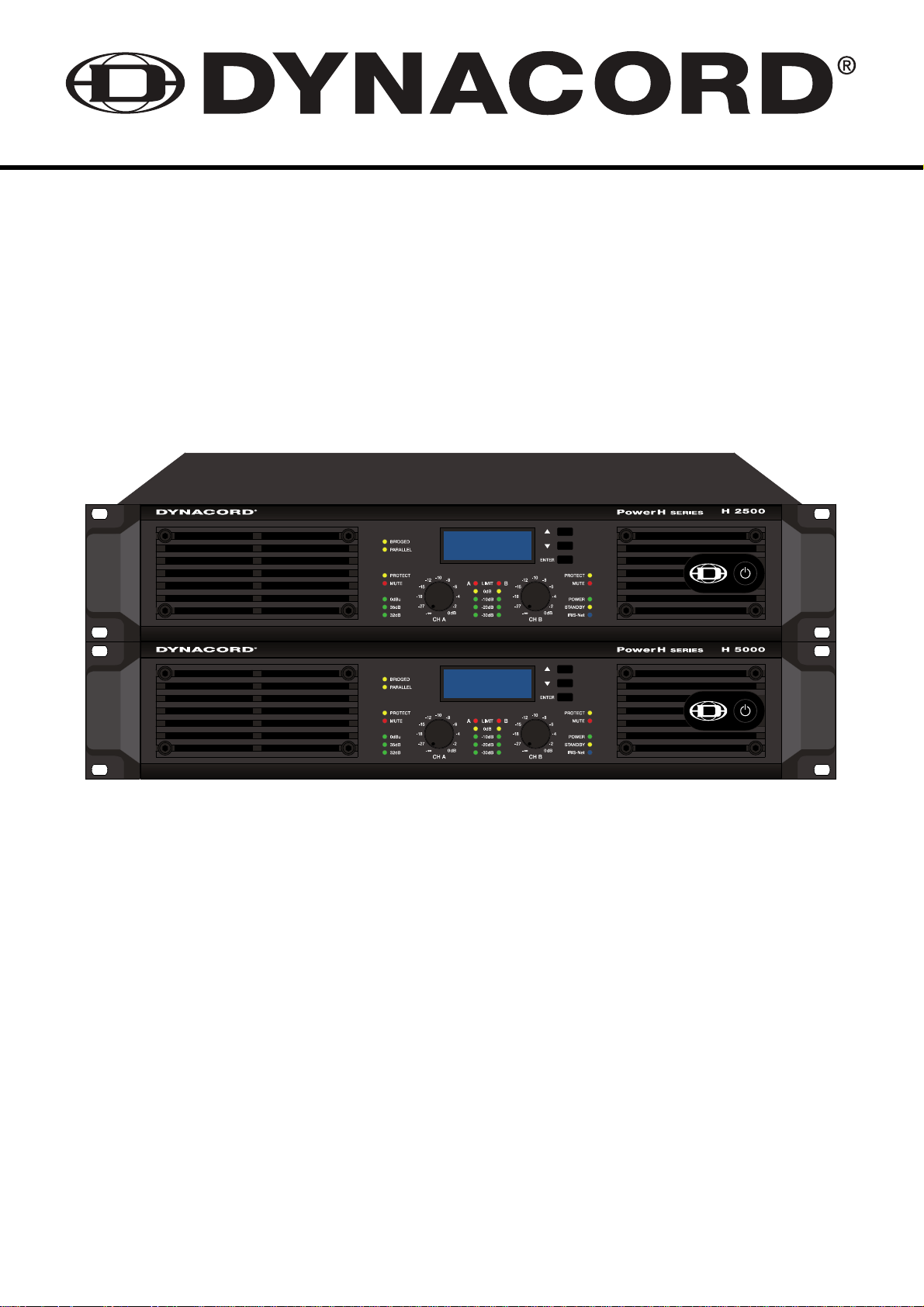
H 2500
H 5000
PowerH
SERIES
Page 2

PowerH SERIES
CONTENTS
Introduction . . . . . . . . . . . . . . . . . . . . . . . . . . . . . . . . . . . . . . . . . . . . . . . . . . . . . . . . . . . . . . . . . 5
Welcome . . . . . . . . . . . . . . . . . . . . . . . . . . . . . . . . . . . . . . . . . . . . . . . . . . . . . . . . . . . . . . 5
Unpacking and Inspection . . . . . . . . . . . . . . . . . . . . . . . . . . . . . . . . . . . . . . . . . . . . . . . . . 5
Scope of Delivery and Warranty . . . . . . . . . . . . . . . . . . . . . . . . . . . . . . . . . . . . . . . . . . . . . 5
Features and Description . . . . . . . . . . . . . . . . . . . . . . . . . . . . . . . . . . . . . . . . . . . . . . . . . . 6
Responsibility of the User . . . . . . . . . . . . . . . . . . . . . . . . . . . . . . . . . . . . . . . . . . . . . . . . . . 6
Installation . . . . . . . . . . . . . . . . . . . . . . . . . . . . . . . . . . . . . . . . . . . . . . . . . . . . . . . . . . . . . . . . . . 7
Controls, Indicators and Connections . . . . . . . . . . . . . . . . . . . . . . . . . . . . . . . . . . . . . . . . 7
Operating Voltage . . . . . . . . . . . . . . . . . . . . . . . . . . . . . . . . . . . . . . . . . . . . . . . . . . . . . . . 9
Mains Switch . . . . . . . . . . . . . . . . . . . . . . . . . . . . . . . . . . . . . . . . . . . . . . . . . . . . . . . . . . . 11
Mounting . . . . . . . . . . . . . . . . . . . . . . . . . . . . . . . . . . . . . . . . . . . . . . . . . . . . . . . . . . . . . . . 12
Ventilation . . . . . . . . . . . . . . . . . . . . . . . . . . . . . . . . . . . . . . . . . . . . . . . . . . . . . . . . . . . . . . 13
Groundlift . . . . . . . . . . . . . . . . . . . . . . . . . . . . . . . . . . . . . . . . . . . . . . . . . . . . . . . . . . . . . . 13
Indication of the Operation Mode . . . . . . . . . . . . . . . . . . . . . . . . . . . . . . . . . . . . . . . . . . . . 14
Selecting the Mode Of Operation . . . . . . . . . . . . . . . . . . . . . . . . . . . . . . . . . . . . . . . . . . . . 14
Operation . . . . . . . . . . . . . . . . . . . . . . . . . . . . . . . . . . . . . . . . . . . . . . . . . . . . . . . . . . . . . . . . . . . 19
Volume Control . . . . . . . . . . . . . . . . . . . . . . . . . . . . . . . . . . . . . . . . . . . . . . . . . . . . . . . . . . 19
Graphical LC display . . . . . . . . . . . . . . . . . . . . . . . . . . . . . . . . . . . . . . . . . . . . . . . . . . . . . 19
Indications . . . . . . . . . . . . . . . . . . . . . . . . . . . . . . . . . . . . . . . . . . . . . . . . . . . . . . . . . . . . . 30
Fan Cooling . . . . . . . . . . . . . . . . . . . . . . . . . . . . . . . . . . . . . . . . . . . . . . . . . . . . . . . . . . . . 31
Air Filter . . . . . . . . . . . . . . . . . . . . . . . . . . . . . . . . . . . . . . . . . . . . . . . . . . . . . . . . . . . . . . . 31
Protections . . . . . . . . . . . . . . . . . . . . . . . . . . . . . . . . . . . . . . . . . . . . . . . . . . . . . . . . . . . . . 32
Options . . . . . . . . . . . . . . . . . . . . . . . . . . . . . . . . . . . . . . . . . . . . . . . . . . . . . . . . . . . . . . . . . . . . 35
RCM-26 . . . . . . . . . . . . . . . . . . . . . . . . . . . . . . . . . . . . . . . . . . . . . . . . . . . . . . . . . . . . . . . 35
INHALT
Einführung . . . . . . . . . . . . . . . . . . . . . . . . . . . . . . . . . . . . . . . . . . . . . . . . . . . . . . . . . . . . . . . . . 48
Willkommen . . . . . . . . . . . . . . . . . . . . . . . . . . . . . . . . . . . . . . . . . . . . . . . . . . . . . . . . . . . . 48
Auspacken und Inspektion . . . . . . . . . . . . . . . . . . . . . . . . . . . . . . . . . . . . . . . . . . . . . . . . . 48
Lieferumfang und Garantie . . . . . . . . . . . . . . . . . . . . . . . . . . . . . . . . . . . . . . . . . . . . . . . . . 48
Eigenschaften & Beschreibung . . . . . . . . . . . . . . . . . . . . . . . . . . . . . . . . . . . . . . . . . . . . . 49
Verantwortung des Betreibers . . . . . . . . . . . . . . . . . . . . . . . . . . . . . . . . . . . . . . . . . . . . . . 49
Installation . . . . . . . . . . . . . . . . . . . . . . . . . . . . . . . . . . . . . . . . . . . . . . . . . . . . . . . . . . . . . . . . . . 50
Bedienelemente, Anzeigen und Anschlüsse . . . . . . . . . . . . . . . . . . . . . . . . . . . . . . . . . . . 50
Betriebsspannung . . . . . . . . . . . . . . . . . . . . . . . . . . . . . . . . . . . . . . . . . . . . . . . . . . . . . . . 52
Netzschalter . . . . . . . . . . . . . . . . . . . . . . . . . . . . . . . . . . . . . . . . . . . . . . . . . . . . . . . . . . . . 54
Einbau . . . . . . . . . . . . . . . . . . . . . . . . . . . . . . . . . . . . . . . . . . . . . . . . . . . . . . . . . . . . . . . . 55
Kühlung . . . . . . . . . . . . . . . . . . . . . . . . . . . . . . . . . . . . . . . . . . . . . . . . . . . . . . . . . . . . . . . 56
Groundlift . . . . . . . . . . . . . . . . . . . . . . . . . . . . . . . . . . . . . . . . . . . . . . . . . . . . . . . . . . . . . . 56
Anzeige der Betriebsart . . . . . . . . . . . . . . . . . . . . . . . . . . . . . . . . . . . . . . . . . . . . . . . . . . . 57
Wahl der Betriebsart . . . . . . . . . . . . . . . . . . . . . . . . . . . . . . . . . . . . . . . . . . . . . . . . . . . . . . 57
Betrieb . . . . . . . . . . . . . . . . . . . . . . . . . . . . . . . . . . . . . . . . . . . . . . . . . . . . . . . . . . . . . . . . . . . . . 63
Volume Control . . . . . . . . . . . . . . . . . . . . . . . . . . . . . . . . . . . . . . . . . . . . . . . . . . . . . . . . . . 63
Graphisches LC-Display . . . . . . . . . . . . . . . . . . . . . . . . . . . . . . . . . . . . . . . . . . . . . . . . . . . 63
Anzeigen . . . . . . . . . . . . . . . . . . . . . . . . . . . . . . . . . . . . . . . . . . . . . . . . . . . . . . . . . . . . . . 74
Lüfter . . . . . . . . . . . . . . . . . . . . . . . . . . . . . . . . . . . . . . . . . . . . . . . . . . . . . . . . . . . . . . . . . 75
Luftfilter . . . . . . . . . . . . . . . . . . . . . . . . . . . . . . . . . . . . . . . . . . . . . . . . . . . . . . . . . . . . . . . . 75
Schutzschaltungen . . . . . . . . . . . . . . . . . . . . . . . . . . . . . . . . . . . . . . . . . . . . . . . . . . . . . . . 76
Optionen . . . . . . . . . . . . . . . . . . . . . . . . . . . . . . . . . . . . . . . . . . . . . . . . . . . . . . . . . . . . . . . . . . . 80
RCM-26 . . . . . . . . . . . . . . . . . . . . . . . . . . . . . . . . . . . . . . . . . . . . . . . . . . . . . . . . . . . . . . . 80
2
Page 3

PowerH SERIES
MATIÈRES
Introduction . . . . . . . . . . . . . . . . . . . . . . . . . . . . . . . . . . . . . . . . . . . . . . . . . . . . . . . . . . . . . . . . . 94
Bienvenue . . . . . . . . . . . . . . . . . . . . . . . . . . . . . . . . . . . . . . . . . . . . . . . . . . . . . . . . . . . . . 94
Déballage et inspection . . . . . . . . . . . . . . . . . . . . . . . . . . . . . . . . . . . . . . . . . . . . . . . . . . . 94
Détails de la livraison et garantie . . . . . . . . . . . . . . . . . . . . . . . . . . . . . . . . . . . . . . . . . . . . 94
Fonctions et description . . . . . . . . . . . . . . . . . . . . . . . . . . . . . . . . . . . . . . . . . . . . . . . . . . . 94
Responsibilité de l’utilisateur . . . . . . . . . . . . . . . . . . . . . . . . . . . . . . . . . . . . . . . . . . . . . . . 95
Installation . . . . . . . . . . . . . . . . . . . . . . . . . . . . . . . . . . . . . . . . . . . . . . . . . . . . . . . . . . . . . . . . . . 96
Commandes, témoins et branchements . . . . . . . . . . . . . . . . . . . . . . . . . . . . . . . . . . . . . . . 96
Tension de fonctionnement . . . . . . . . . . . . . . . . . . . . . . . . . . . . . . . . . . . . . . . . . . . . . . . . 98
Interrupteur secteur . . . . . . . . . . . . . . . . . . . . . . . . . . . . . . . . . . . . . . . . . . . . . . . . . . . . . . 100
Montage . . . . . . . . . . . . . . . . . . . . . . . . . . . . . . . . . . . . . . . . . . . . . . . . . . . . . . . . . . . . . . . 101
Ventilation . . . . . . . . . . . . . . . . . . . . . . . . . . . . . . . . . . . . . . . . . . . . . . . . . . . . . . . . . . . . . . 102
Mise à la masse . . . . . . . . . . . . . . . . . . . . . . . . . . . . . . . . . . . . . . . . . . . . . . . . . . . . . . . . . 103
Témoin du mode de fonctionnement . . . . . . . . . . . . . . . . . . . . . . . . . . . . . . . . . . . . . . . . . 103
Choix du mode de fonctionnement . . . . . . . . . . . . . . . . . . . . . . . . . . . . . . . . . . . . . . . . . . . 103
Fonctionnement . . . . . . . . . . . . . . . . . . . . . . . . . . . . . . . . . . . . . . . . . . . . . . . . . . . . . . . . . . . . . 109
Contrôle du volume . . . . . . . . . . . . . . . . . . . . . . . . . . . . . . . . . . . . . . . . . . . . . . . . . . . . . . 109
Écran LCD graphique . . . . . . . . . . . . . . . . . . . . . . . . . . . . . . . . . . . . . . . . . . . . . . . . . . . . . 109
Indications . . . . . . . . . . . . . . . . . . . . . . . . . . . . . . . . . . . . . . . . . . . . . . . . . . . . . . . . . . . . . 120
Refroidissement par ventilateur . . . . . . . . . . . . . . . . . . . . . . . . . . . . . . . . . . . . . . . . . . . . . 121
Filtres à air . . . . . . . . . . . . . . . . . . . . . . . . . . . . . . . . . . . . . . . . . . . . . . . . . . . . . . . . . . . . . 121
Protections . . . . . . . . . . . . . . . . . . . . . . . . . . . . . . . . . . . . . . . . . . . . . . . . . . . . . . . . . . . . . 122
Options . . . . . . . . . . . . . . . . . . . . . . . . . . . . . . . . . . . . . . . . . . . . . . . . . . . . . . . . . . . . . . . . . . . . 125
RCM-26 . . . . . . . . . . . . . . . . . . . . . . . . . . . . . . . . . . . . . . . . . . . . . . . . . . . . . . . . . . . . . . . 125
Specifications/Technische Daten . . . . . . . . . . . . . . . . . . . . . . . . . . . . . . . . . . . . . . . . . . . . . . . 135
Block Diagram / Blockschaltbild . . . . . . . . . . . . . . . . . . . . . . . . . . . . . . . . . . . . . . . . . . . . . . . . 139
Dimensions / Abmessungen . . . . . . . . . . . . . . . . . . . . . . . . . . . . . . . . . . . . . . . . . . . . . . . . . . . 140
Declaration of conformity . . . . . . . . . . . . . . . . . . . . . . . . . . . . . . . . . . . . . . . . . . . . . . . . . . . . . 141
3
Page 4
PowerH SERIES
IMPORTANT SAFETY INSTRUCTIONS
The lightning flash with arrowhead symbol, within
an equilateral triangle is intended to alert the user
to the presence of uninsulated “dangerous
voltage“ within the product’s enclosure that may
be of sufficent magnitude to constitute a risk of
electric shock to persons.
The exclamation point within an equilateral triangle is intended to alert the user to the presence
of important operating and maintenance (servicing) instructions in the literature accompanying
the product.
1. Read these instructions.
2. Keep these instructions.
3. Heed all warnings.
4. Follow all instructions.
5. Do not use this apparatus near water.
6. Clean only with a dry cloth.
7. Do not block any ventilation openings. Install in accordance with the manufacture’s instructions.
8. Do not install near heat sources such as radiators, heat registers, stoves, or other apparatus (including amplifiers) that produce heat.
9. Do not defeat the safety purpose of the polarized or the grounding-type plug. A polarized plug has two blades with one wider than the other.
A grounding type plug has two blades and a third grounding prong. The wide blade or the third prong are provided for your safety. If the
provided plug does not fit into your outlet, consult an electrician for replacement of the obsolete outlet.
10. Protect the power cord from being walked on or pinched particularly at plugs, convenience receptacles, and the point where they exit from
the apparatus.
11. Only use attachments/accessories specified by the manufacturer.
12. Use only with the cart, stand, tripod, bracket, or table specified by the manufacturer, or sold with the apparatus. When a cart is used, use
caution when moving the cart/apparatus combination to avoid injury from tip-over.
13. Unplug this apparatus during lightning storms or when unused for a long period of time.
14. Refer all servicing to qualified service personnel. Servicing is required when the apparatus has been damaged in any way, such as powersupply cord or plug is damaged, liquid has been spilled or objects have fallen into the apparatus, the apparatus has been exposed to rain or
moisture, does not operate normally, or has been dropped.
15. Do not expose this equipment to dripping or splashing and ensure that no objects filled with liquids, such as vases, are placed on the
equipment.
16. To completely disconnect this equipment from the AC Mains, disconnect the power supply cord plug from the AC receptacle.
17. The mains plug of the power supply cord shall remain readily operable.
Management of WEEE (waste electrical and electronic equipment) (applicable in Member States of the European Union and other European countries with individual national policies on the management of WEEE) The
symbol on the product or on its packaging indicates that this product may not be treated as regular household
waste, but has to be disposed through returning it at a Telex dealer.
IMPORTANT SERVICE INSTRUCTIONS
CAUTION: These servicing instructions are for use by qualified personnel only. To reduce the risk of electric shock, do not perform any
servicing other than that contained in the Operating Instructions unless you are qualified to do so. Refer all servicing to qualified
service personnel.
1. Security regulations as stated in the EN 60065 (VDE 0860 / IEC 65) and the CSA E65 - 94 have to be obeyed when servicing the appliance.
2. Use of a mains separator transformer is mandatory during maintenance while the appliance is opened, needs to be operated and is
connected to the mains.
3. Switch off the power before retrofitting any extensions, changing the mains voltage or the output voltage.
4. The minimum distance between parts carrying mains voltage and any accessible metal piece (metal enclosure), respectively between the
mains poles has to be 3 mm and needs to be minded at all times. The minimum distance between parts carrying mains voltage and any
switches or breakers that are not connected to the mains (secondary parts) has to be 6 mm and needs to be minded at all times.
5. Replacing special components that are marked in the circuit diagram using the security symbol (Note) is only permissible when using
original parts.
6. Altering the circuitry without prior consent or advice is not legitimate.
7. Any work security regulations that are applicable at the locations where the appliance is being serviced have to be strictly obeyed. This
applies also to any regulations about the work place itself.
8. All instructions concerning the handling of MOS-circuits have to be observed.
NOTE: SAFETY COMPONENT (MUST BE REPLACED BY ORIGINAL PART)
4 Owner’s Manual
Page 5

PowerH SERIES
1 Introduction
1.1 Welcome
Dynacord’s new PowerH SERIES power amps herald a new age in power amplifier technology.
These highly efficient PowerH amplifiers combine uncompromising audio performance with low weight
and highest reliability. Optionally available remote control modules provide the possibility to completely
control and monitor the power amps via IRIS-Net™.
1.2 Unpacking and Inspection
Carefully open the packaging and take out the power amplifier. Inspect the power amp’s enclosure for
damages that might have happened during transportation. Each amplifier is examined and tested in detail
before leaving the manufacturing site to ensure that it arrives in perfect condition at your place. Please
inform the transport company immediately, if the power amplifier shows any damage. Being the
addressee, you are the only person who can claim damages in transit. Keep the cardboard box and all
packaging materials for inspection by the transport company.
Keeping the cardboard box including all packing materials is also recommended, if the power amplifier
shows no external damages.
CAUTION:
Do not ship the power amp in any other but its original packaging.
When shipping the power amp, make sure to always use its original box and packaging materials. Packing
the power amplifier like it was packed by the manufacturer guarantees optimum protection from transport
damage.
1.3 Scope of Delivery and Warranty
• 1 Power Amplifier H2500/H5000
• 1 Owner’s Manual (this document)
• 2 Phoenix-type Plugs
• 1 Mains Cord
• 2 Rack-mount Ears
• 4 Case Nuts
• 4 Foot Stands
• 1 Warranty Certificate
Keep the original invoice that states the purchase/delivery date together with the warranty certificate at a
safe place.
Owner’s Manual 5
Page 6

PowerH SERIES
1.4 Features and Description
The power amp H2500/H5000 is part of Dynacord’s new PowerH SERIES, which marks a
milestone in the design and the production of high-performance power amplifiers. The innovative 3-stage
Grounded Bridge Class H Topology with “floating” switching power supply unit offers very high and stable
output with extreme high efficiency on an extremely high performance level at minimum weight.
PowerH amps are ideal for driving professional touring, high-end Concert-Sound and Pro-Sound
applications.
Next to classical protections, this new design employs the multi-stage ATP system (Advanced Thermal
Protection) for the first time, which in most cases prevents the power amplifier from switching off when the
temperature exceeds a critical level. The newly designed MCS system (Mains Current Supervision)
prevents power amplifier breakdown caused by the activation of the automatic circuit breaker.
For this, among other things, the MCS system uses the highly precise measurement of the RMS value of
the actual mains current consumption. Information about the status of the power amplifier and its internal
protections is provided on a LC-display. By utilizing the optionally available remote control module that is
compatible with IRIS-Net™, this power amplifier additionally offers comprehensive remote monitoring and
remote control functions plus a universal 2-channel digital audio controller (DSP) including highly precise
FIR-filtering and digital speaker protection algorithms.
1.5 Responsibility of the User
Speaker System Damage
PowerH power amps provide extremely high power output that might be dangerous for human beings
as well as for the connected speaker systems. High output voltages can damage or even destroy the
connected speaker systems, especially, when the PowerH amplifier is operated in bridged mode. Prior
to connecting any loudspeakers, make sure to check the speaker system’s specifications for continuous
and peak power handling capacities. Even if amplification has been reduced through lowering the input
level controls on the amplifier’s front panel, it is still possible to achieve full power output with a sufficiently
high input signal.
Dangers at the Loudspeaker/Power Outputs
PowerH amplifiers are capable of producing dangerously high voltage output that is present at the
output connectors. To protect yourself from electric shock, do not touch any blank speaker cables during
operation of the power amp.
HF-Interference
This equipment has been tested and found to comply with the limits for a Class B digital device, pursuant
to Part 15 of the FCC Rules. These limits are designed to provide reasonable protection agains harmful
interference in a residential installation. This equipment generates, uses and can radiate radio frequency
energy and, if not installed and used in accordance with the instructions, may cause harmful interference
to radio communications. However, there is no guarantee that interference will not occur in a particular
installation. If this equipment does cause harmful interference to radio or televsion reception, which can be
determined by turning the equipment off and on, the user is encouraged to try to correct the interference by
one or more of the following measures:
• Reorient or relocate the receiving antenna
• Increase the separation between the equipment and receiver
• Connect the equipment into an outlet on a circuit different from that to which the receiver is connected
• Consult the dealer or an experienced radio/TV technician for help
6 Owner’s Manual
Page 7
2 Installation
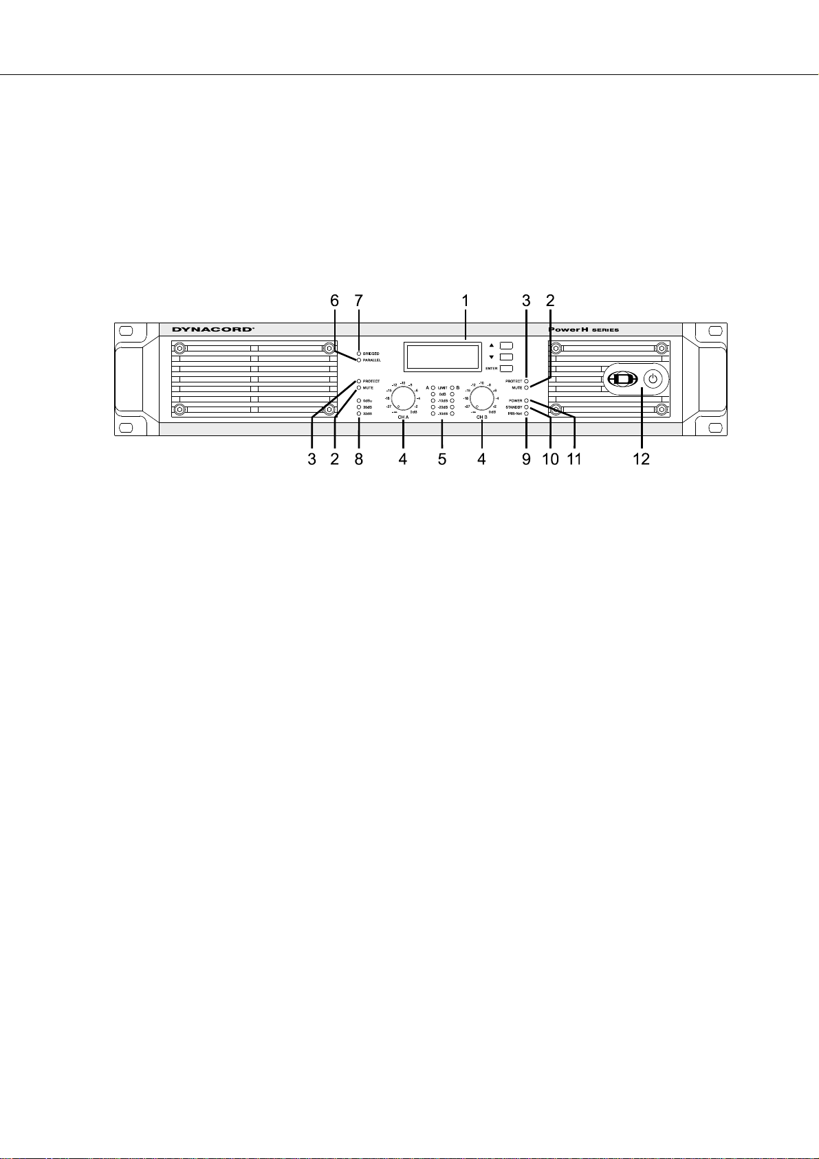
2.1 Controls, Indicators and Connections
Front View
PowerH SERIES
Illustration 2.1: H2500/H5000 front view
LC-Display (with controls)
1
Muting Indicator (MUTE) for channels A and B
2
Protections Indicator (PROTECT) for channels A and B
3
Input Level Control (CH A, CH B) for channels A and B
4
Level Indicators for channels A and B
5
Audio Input Mode Indicator (PARALLEL)
6
Power Amplifier Mode Indicator (BRIDGED)
7
Input Sensitivity/Gain Indicator (0dBu, 35dB, 32dB)
8
Remote Amplifier Indicator (IRIS-Net)
9
Standby Indicator (STANDBY)
10
Power On/Off Indicator (POWER)
11
Mains Switch
12
Owner’s Manual 7
Page 8
PowerH SERIES
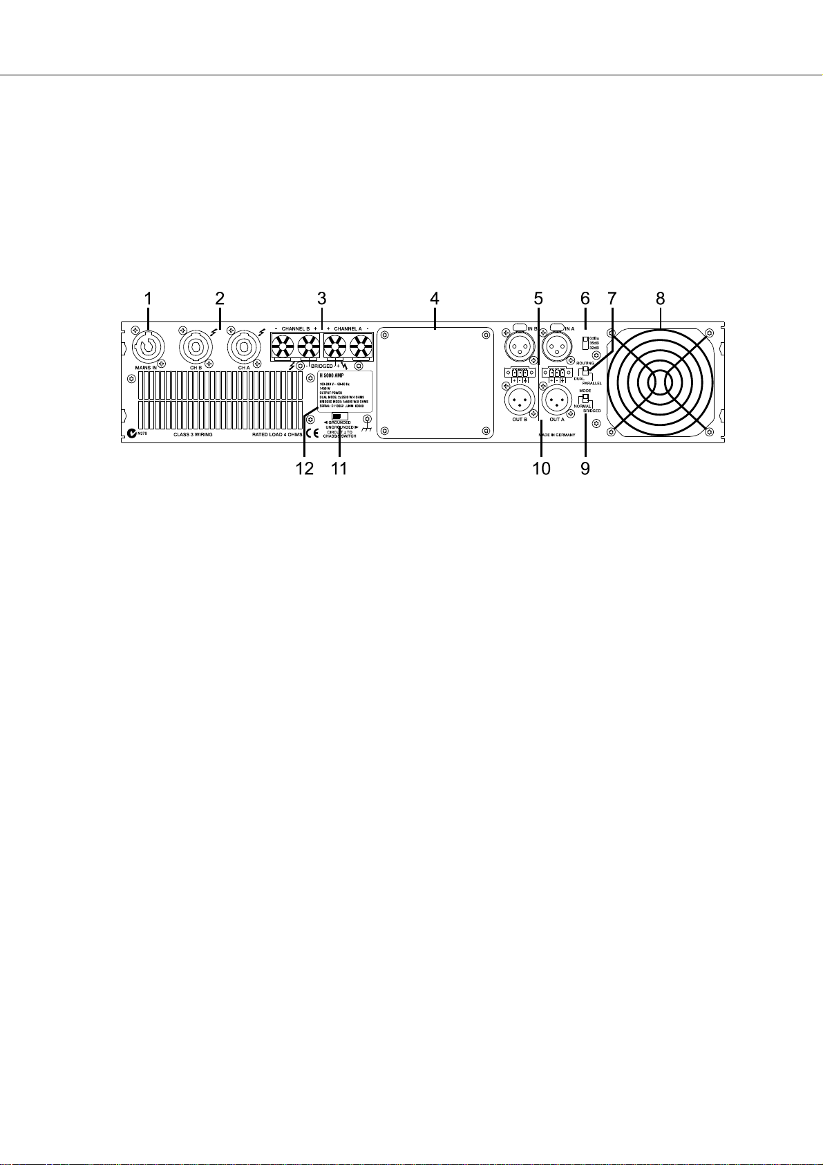
Rear View
Illustration 2.2: H2500/H5000 rear view
PowerCon® Mains Input (MAINS IN)
1
Speakon™ Female-Type Power Amp Outputs (CH A, CH B)
2
Power Amp Output Terminals (CHANNEL A, CHANNEL B, BRIDGED)
3
Expansion Slot
4
XLR and Phoenix-Type Audio Inputs (IN A, IN B)
5
Input Sensitivity/Gain Switch
6
Audio Inputs Routing Switch (ROUTING)
7
Fan
8
Power Amp Outputs Mode Switch (MODE)
9
XLR-Type Audio Outputs (OUT A, OUT B)
10
Ground Lift Switch (CIRCUIT ⊥ TO CHASSIS SWITCH)
11
Type Plate
12
8 Owner’s Manual
Page 9
PowerH SERIES
Factory Settings
Control Setting
Mains Switch off
Level CH A 0dB
Level CH B 0dB
Table 2.1: Factory Settings of the Controls
Parameter Value
Power-On-Delay 0.00 s
Breaker Current (dependent on the mains) 16 A (230 V) / 30 A (120 V)
Amplifier Name Dynacord H2500 or Dynacord H5000
LCD Contrast 50%
LCD Brightness High 90%
LCD Brightness Low 40%
LCD Time to Dim Autodim off
Temperature Unit °C
Table 2.2: Factory Settings of the LC-Display
Controls Setting
ROUTING DUAL
MODE NORMAL
SENSITIVITY/GAIN 0dBu
GROUNDLIFT GROUNDED
Table 2.3: Factory Settings of the Rear Panel Controls
2.2 Operating Voltage
The power amplifier receives its power supply via the MAINS IN connector, which is designed as a Neutrik
PowerCon® connector.
CAUTION:
The Powercon
® is a connector without breaking capacity, i.e. the Powercon® should
not be connected or disconnected under load or live.
Owner’s Manual 9
Page 10
PowerH SERIES
During installation, always separate the power amplifier from the mains. Connect the power amplifier only
to a mains network, which corresponds to the requirements indicated on the type plate.
Illustration 2.3: H2500/H5000 type plate
Device Voltage Frequency Power Consumption
H2500 100-240 V 50-60 Hz 1000 W
H5000 100-240 V 50-60 Hz 1450 W
Table 2.4: Specifications for the Power Supply Unit
Mains Operation & Resulting Temperature
The following tables allow the determination of power supply and cabling requirements. The power drawn
from the mains network is converted into output power to feed the connected loudspeaker systems and
into heat. The difference between power consumption and dispensed power is called power dissipation
(P
). The amount of heat resulting from power dissipation might remain inside of a rack-shelf and needs to
d
be diverted using appropriate measures. The following table is meant as auxiliary means for calculating
temperatures inside of a rack-shelf system/cabinet and the ventilation efforts necessary.
The column P
the dispensed heat amount per hour.
Idle 230 0.7 70 - 70 239
Max. Output Power @ 8 Ω
Max. Output Power @ 4 Ω
1/3 Max. Output Power @ 4 Ω
1/8 Max. Output Power @ 4 Ω
1/8 Max. Output Power @ 4 Ω
1/8 Max. Output Power @ 4 Ω
Normal Mode (-10 dB) @ 4 Ω
Rated Output Power (0 dB) @ 4 Ω
Alert (Alarm) Mode (-3 dB) @ 4 Ω
Max. Output Power @ 2 Ω
1/8 Max. Output Power @ 2 Ω
1/8 Max. Output Power @ 2 Ω
lists the leakage power in relation to different operational states. The column BTU/hr lists
d
H2500
U
in V I
mains
3
3
3
3
4
4 5
3
3
3
3
3
4
230 15.3 2420 2 x 850 720 2457
230 25.7 4300 2 x 1450 1400 4777
230 14.7 2325 2 x 483 1358 4635
230 6.2 875 2 x 181 513 1749
230 6.7 1000 2 x 181 588 2005
253 7.1 1105 2 x 219 666 2274
230 5.6 775 2 x 145 485 1655
230 23.5 3900 2 x 1200 1500 5118
230 16.7 2665 2 x 600 1465 4999
230 39.6 6920 2 x 2000 2920 9963
230 9.1 1345 2 x 238 870 2969
230 9.1 1335 2 x 238 860 2934
mains
in A P
mains
in W P
out
in W
Pd in W
1
BTU/hr
2
10 Owner’s Manual
Page 11
PowerH SERIES
H5000
Idle 230 0.7 78 - 78 266
Max. Output Power @ 8 Ω
Max. Output Power @ 4 Ω
1/3 Max. Output Power @ 4 Ω
1/8 Max. Output Power @ 4 Ω
1/8 Max. Output Power @ 4 Ω
1/8 Max. Output Power @ 4 Ω
Normal Mode (-10 dB) @ 4 Ω
Rated Output Power (0 dB) @ 4 Ω
Alert (Alarm) Mode (-3 dB) @ 4 Ω
Max. Output Power @ 2 Ω
1/8 Max. Output Power @ 2 Ω
1/8 Max. Output Power @ 2 Ω
= Power Dissipation
1.P
d
2.1 BTU = 1055.06 J = 1055.06 Ws
3.Sine Modulation (1 kHz)
4.Pink-Noise EN60065 / 7. Edition
5.10% Mains Over Voltage
3
3
3
3
4
4 5
3
3
3
3
3
4
The following factors allow direct proportional calculation of the mains current I
U
in V I
mains
230 24.5 4089 2 x 1500 1089 3716
230 40.9 7137 2 x 2500 2137 7292
230 18.1 2927 2 x 833 1260 4300
230 6.2 877 2 x 313 252 860
230 9.6 1450 2 x 313 806 2750
253 11.6 1944 2 x 378 1188 4053
230 9.2 1368 2 x 250 868 2962
230 37.5 6445 2 x 2100 2245 7660
230 22.7 3760 2 x 1050 1660 5664
230 44.3 8180 2 x 3500 1180 4026
230 15.3 2427 2 x 438 1552 5296
230 13.6 2105 2 x 438 1230 4197
mains
in A P
mains
in W P
out
in W
mains
1
Pd in W
for different mains
supply voltages: 100 V = 2.3, 120 V = 1.9, 220 V = 1.05, 240 V = 0.97.
BTU/hr
2
2.3 Mains Switch
The Mains Switch on the front panel separates the power
amp from the mains. Pressing the Mains Switch starts
booting up the power amp. A soft start circuit compensates
mains inrush current peaks and thus prevents the automatic
cutout of the mains from reacting when switching on the
power amplifier. Speaker system switch-on is delayed by
approximately 2 seconds via output relays, effectively
suppressing any possible power-on noise, which otherwise
might be heard through the loudspeakers. MUTE-LED light
and the fans are running during this delay.
Owner’s Manual 11
Page 12
PowerH SERIES
2.4 Mounting
Front Mounting of the Power Amplifier
PowerH amplifiers have been designed for installation in a conventional 19-inch rack case. Attach the
power amp with its frontal rack mount ears using 4 screws and washers as shown in illustration 2.4.
Illustration 2.4: Front mounting when installing the power amplifier in a rack case
Rear Mounting
Additionally securing the amplifier at the rear becomes necessary, if the rack case in which the power
amplifier has been installed will be transported. Failure to do so may result in damage to the power
amplifier as well as to the rack case. Brackets for securing the power amplifier are supplied. Attach the
power amp as shown in illustration 2.5 using the supplied 4 case nuts and screws.
Illustration 2.5: Rear mounting when installing the power amplifier in a rack case
12 Owner’s Manual
Page 13
PowerH SERIES
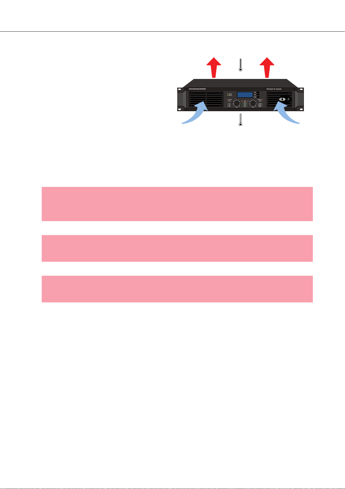
2.5 Ventilation
As with all Dynacord power amps with fan
cooling, the airflow direction is front-to-rear,
obviously because there is more cold air
outside of the rack case than inside. The power
amplifier remains cooler and dissipating the
developing waste heat in a specific direction
gets easier. In general, setting up or mounting
the power amplifier has to be done in a way that
fresh air can enter unhindered at the front and
exhausted air can exit at the rear. When
installing the power amp in a case or rack
system, attention should be paid to these details
to provide sufficient ventilation. Allow for an air duct of at least 60 mm x 330 mm between the rear panel of
the power amplifier and the inner wall of the cabinet/rack case. Make sure that the duct reaches up to the
cabinet’s or the rack case’s top ventilation louvers. Leave room of at least 100 mm above the cabinet/rack
case for ventilation. Since temperatures inside of the cabinet/rack case can easily rise up to 40 °C during
operation of the power amp, it is mandatory to bear in mind the maximum allowable ambient temperature
for all other appliances installed in the same cabinet/rack case.
Illustration 2.6: H2500/H5000 Ventilation
CAUTION:
Blocking/closing the power amp’s ventilation louvers is not permissible. Without
sufficient cooling/ventilation, the power amplifier may automatically enter protect
mode. Keep ventilation louvers free from dust to ensure unhindered airflow.
CAUTION:
Do not use the power amplifier near heat sources, like heater blowers, stoves or any
other heat radiating devices.
CAUTION:
To ensure trouble-free operation, make certain that the maximum allowable ambient temperature of +40 °C is not exceeded.
For fixed amplifier installations in a device control room that incorporate a central air-cooling system or air
conditioners, calculating the maximum heat emission may be necessary. Please also take notice of the
information on page 10.
2.6 Groundlift
The ground lift switch allows eliminating noise loops. When operating the power amplifier together with
other equipment in a rack case, setting the switch to the GROUNDED position is recommended. Set the
switch to UNGROUNDED, when the power amplifier is operated together with appliances with differing
ground potentials.
Owner’s Manual 13
Page 14
PowerH SERIES
2.7 Indication of the Operation Mode
Two LEDs on the power amp’s front panel indicate the currently selected mode of operation. The
PARALLEL-LED lights yellow, when the ROUTING switch is set to PARALLEL. The PARALLEL LED does
not light, when the switch is set to DUAL. The BRIDGED LED lights yellow, when the MODE switch is set
to BRIDGED. The BRIDGED LED does not light, when the switch is set to NORMAL.
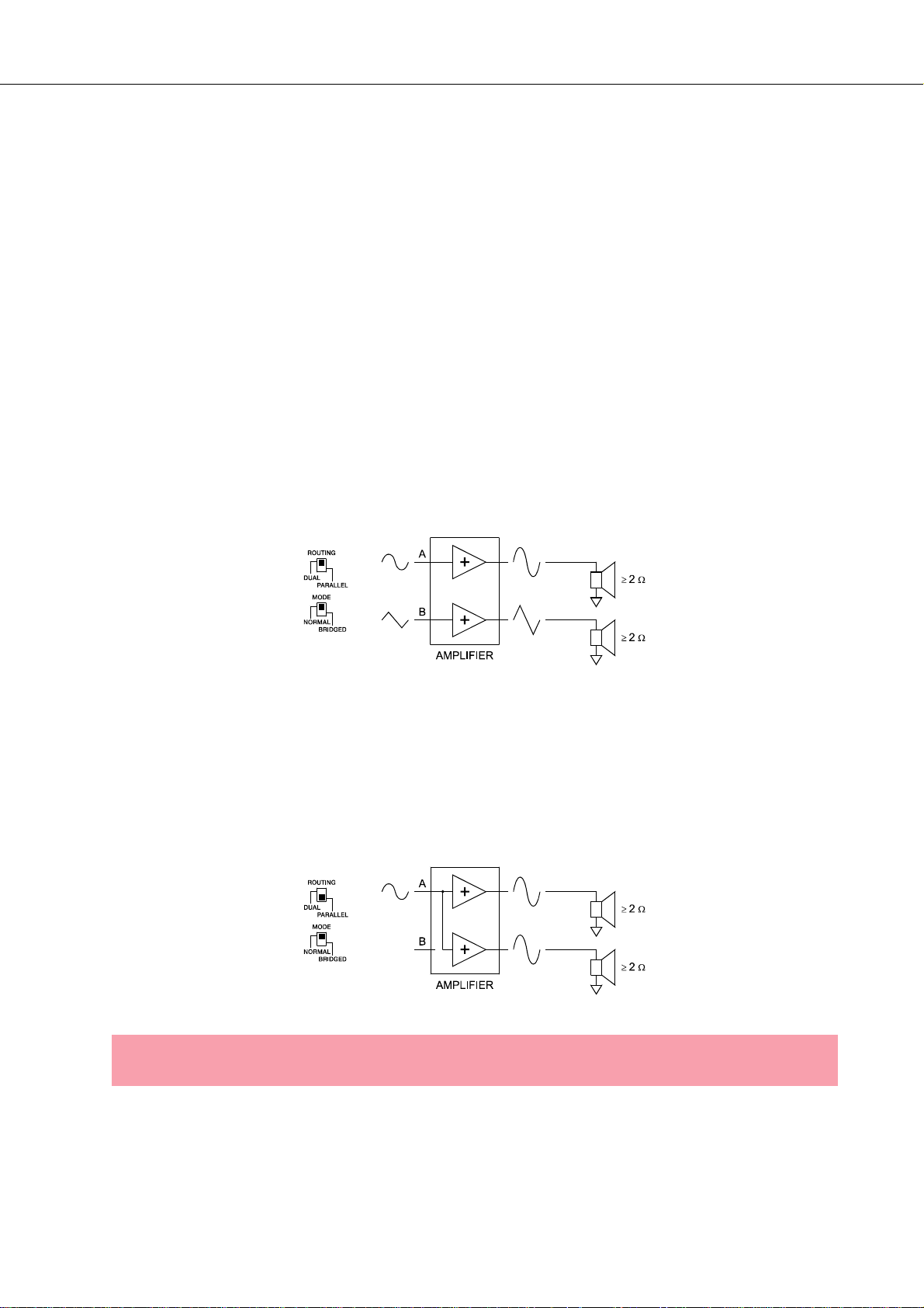
2.8 Selecting the Mode Of Operation
ROUTING
The ROUTING switch on the power amp’s rear panel defines how the audio inputs handle the input
signals.
DUAL
In DUAL mode, the two channels of the power amplifier work independent from each other. This mode of
operation is being used for all 2-channel applications, like stereo or Bi-Amp (active) operation. Using the
input level controls on the power amp’s front panel or an optionally available remote control module and
IRIS-Net™ allows independently adjusting the channels’ amplification.
Illustration 2.7: Audio signal applied to both input connectors in DUAL mode
PARALLEL
In PARALLEL mode, the inputs of channel A and channel B are directly electrically linked. The audio signal
has to be applied to the input connectors (XLR or Phoenix) of channel A. Using the input level controls or
IRIS-Net™ to independently control the amplification of the two channels is still possible because only the
channels’ inputs are linked. PARALLEL operation is the mode of choice, whenever the same input signal
drives multiple power amp channels of a large system installation, e.g. when driving massive bass arrays.
Illustration 2.8: Audio signal applied to input connector A in PARALLEL mode
CAUTION:
In PARALLEL mode, the input signal has to be fed to input channel A only.
14 Owner’s Manual
Page 15
PowerH SERIES
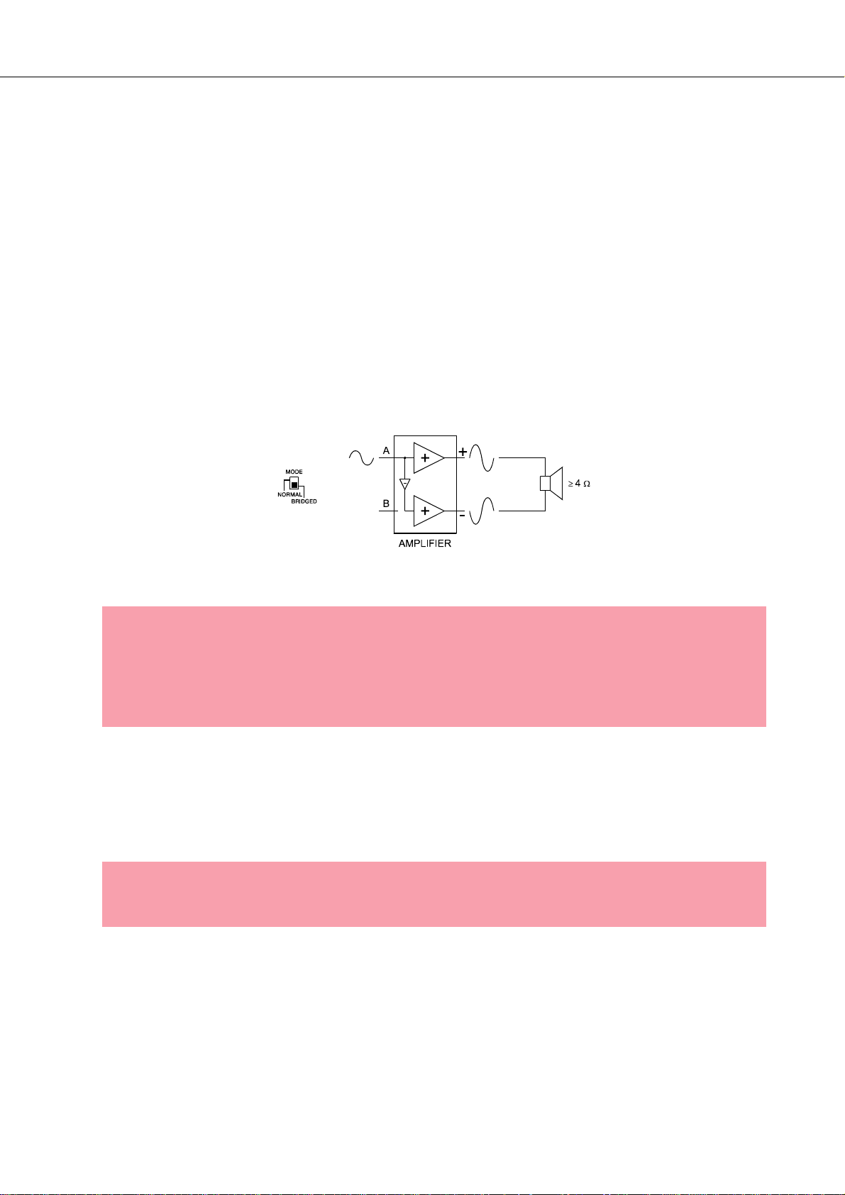
MODE
The MODE switch on the power amp’s rear panel defines the operation mode of the power amplifier blocks
and thus, how a single or more speaker systems have to be connected.
NORMAL
In two-channel operation (NORMAL), both power amplifier blocks work as independent power amp
channels and controlling the amplification of each channel separately is possible. How the power amp’s
audio inputs handle input signals depends only on the setting of the ROUTING switch.
BRIDGED
In BRIDGED mode, the power amplifier functions as single-channel, monaural power amp. If the switch is
set to DUAL (input channels work independent from each other), the audio signal has to be applied to
either one of the input connectors (XLR or Phoenix) of channel A while channel B inputs are inactive. With
the switch being set to PARALLEL, the audio signal may be fed to either one of the inputs of channel A or
of channel B. In BRIDGED mode, the power amp channel A is modulated as usual.In addition, the input
signal is internally inverted and applied to channel B. The A and B power amps act in push-pull operation
delivering doubled output voltage.
Illustration 2.9: BRIDGED mode
CAUTION:
In BRIDGED mode operation, it is not allowable for the load connected to fall below a value of 4 ohms. Extremely high voltages can be present at the output. The connected
speaker systems must be able to handle such voltages. Make sure to completely read
and fully observe power rating specifications of the speaker systems to be used and to
check them against the output power capacity of the power amp.
SENSITIVITY/GAIN
PowerH SERIES amplifiers can be operated at an input sensitivity of 0dBu as well as at a constant
gain of 35dB or 32dB. A correspondingly labeled LED on the power amp’s front panel indicates the
respective setting of the sensitivity/gain switch, which is located on the power amp’s rear panel.
NOTE:
If a remote control module is used the sensitivity/gain switch is deactivated and the sensitivity/gain of the amplfier is automatically set to 35 dB.
An Input sensitivity of 0dBu means that with an input signal of 0 dBu (0.775 Vrms), the signal at the power
amplifier outputs is at Rated Output Power. This setting is recommended for audio signal sources that
deliver a nominal output voltage of 0 dBu. As an alternative, operating the power amp at a constant gain of
35 dB or 32 dB is also possible. Operating all power amps in a setup – even those of different performance
classes – at constant gain setting greatly simplifies the adjustment of signal processors. This allows the
Owner’s Manual 15
Page 16
PowerH SERIES
installer to consider each power amplifier with a gain of 35 dB (or 32 dB) when setting gain structure,
independent of the actual maximum output capacity of each individual power amp. Any limiters have to be
adjusted to maximum power handling capacity of the loudspeaker components.
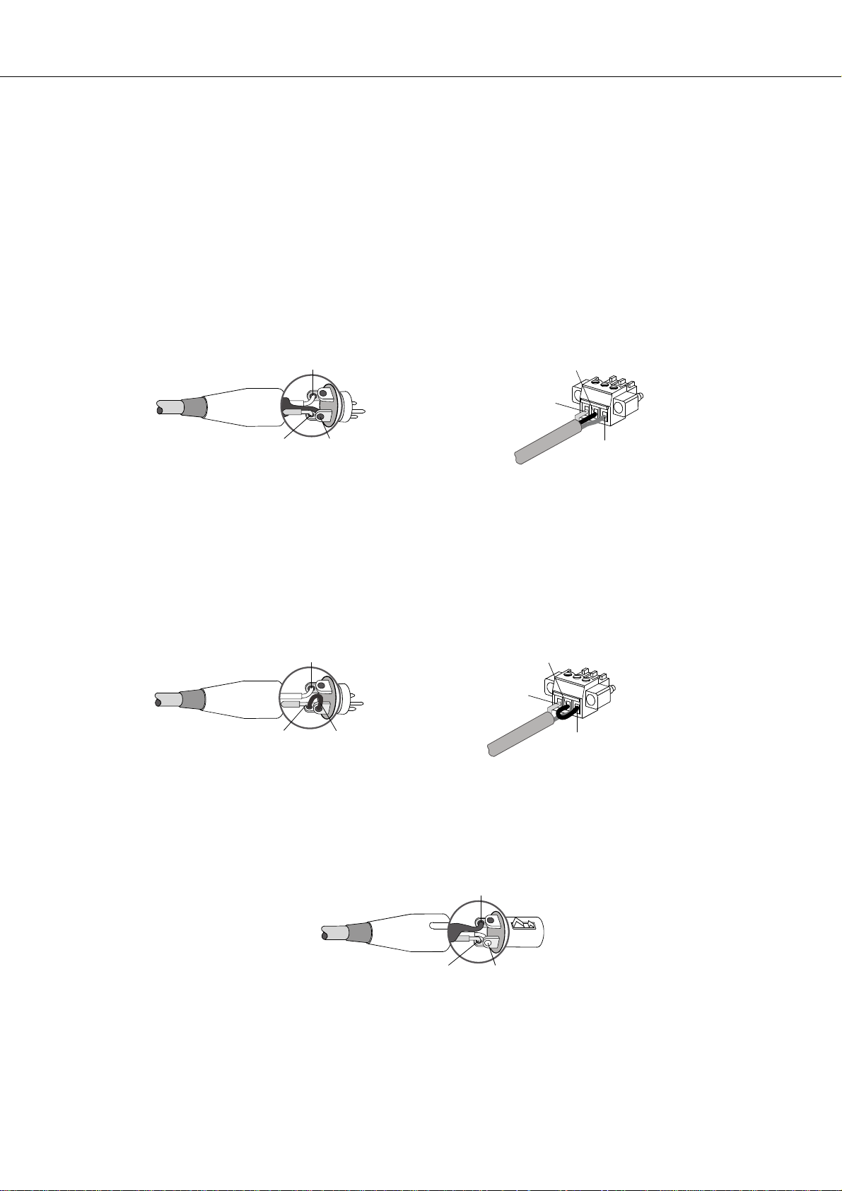
Audio Cabling
Input (XLR / Phoenix)
Inputs IN A and IN B are electronically balanced and the SENSITIVITY switch controls input sensitivity.
Connection can be established either by using XLR- or Phoenix-type connectors, which are connected in
parallel. The needed Phoenix-type connectors are supplied with the power amplifier. The pin-assignment
of XLRF-type connectors is in accordance with the IEC standard 268.
3, COLD
2, HOT
1, SHIELD
COLD, -
HOT, +
SHIELD
Illustration 2.10: Balanced connection of input
Whenever possible, using balanced audio signal feeds at the input of the power amplifier is always
preferred. Unbalanced connections should only be used if the cables are very short and no interfering
signals are to be expected in the vicinity of the power amplifier. In this case, bridging the screen (shielding)
and the pin of the inverting input inside of the connector is mandatory. Otherwise, a 6 dB drop in level
could result. Please also see illustration 2.11. Due to their immunity against external interference sources,
such as dimmers, mains connections, HF-control lines, etc., using balanced cabling and connections is
always preferable.
3, COLD
2, HOT
JUMPER
FROM COLD
TO SHIELD
JUMPER FROM COLD TO SHIELD
HOT, +
SHIELD
Illustration 2.11: Unbalanced connection of input
Next to its input connector, each channel provides an individual XLR-type connector (OUT A or OUT B),
which is connected in parallel to allow for comfortably daisy-chaining the audio signal for the connection of
additional audio equipment.
1, SHIELD
3, COLD
2, HOT
Illustration 2.12: Balanced connection of output (Daisy-Chain)
16 Owner’s Manual
Page 17
PowerH SERIES
Output (Speakon-type Connectors / Terminals) in Normal Mode
With PowerH SERIES amplifiers speaker connection differs depending on the actually selected
mode of operation of the power amplifier blocks, i.e. the setting of the MODE switch on the power amp’s
rear panel. In NORMAL mode, the loudspeaker systems can be connected in two different ways: using
typical Speaker Systems Cabling or Bi-Amp Cabling.
Typical Speaker System Cabling
The first possibility is to use the two Speakon-type connectors, whereas speakers have to be connected to
pins 1+ and 1– of the sockets, see illustration 2.13.
Illustration 2.13: Speaker connection in NORMAL operation mode, using Speakon A and B connectors
Speakon CH B Speakon CH A
1+ 1-
B+ B-
Connector 1+ 1-
Assignment A+ A-
Table 2.5: Speaker connection in NORMAL operation mode, using Speakon A and B connectors
Next to the Speakon-type sockets, conventional speaker terminals are provided as well. The following
illustration shows how to connect the speaker systems for NORMAL mode operation.
Illustration 2.14: Speaker connection in NORMAL operation mode, using Terminals
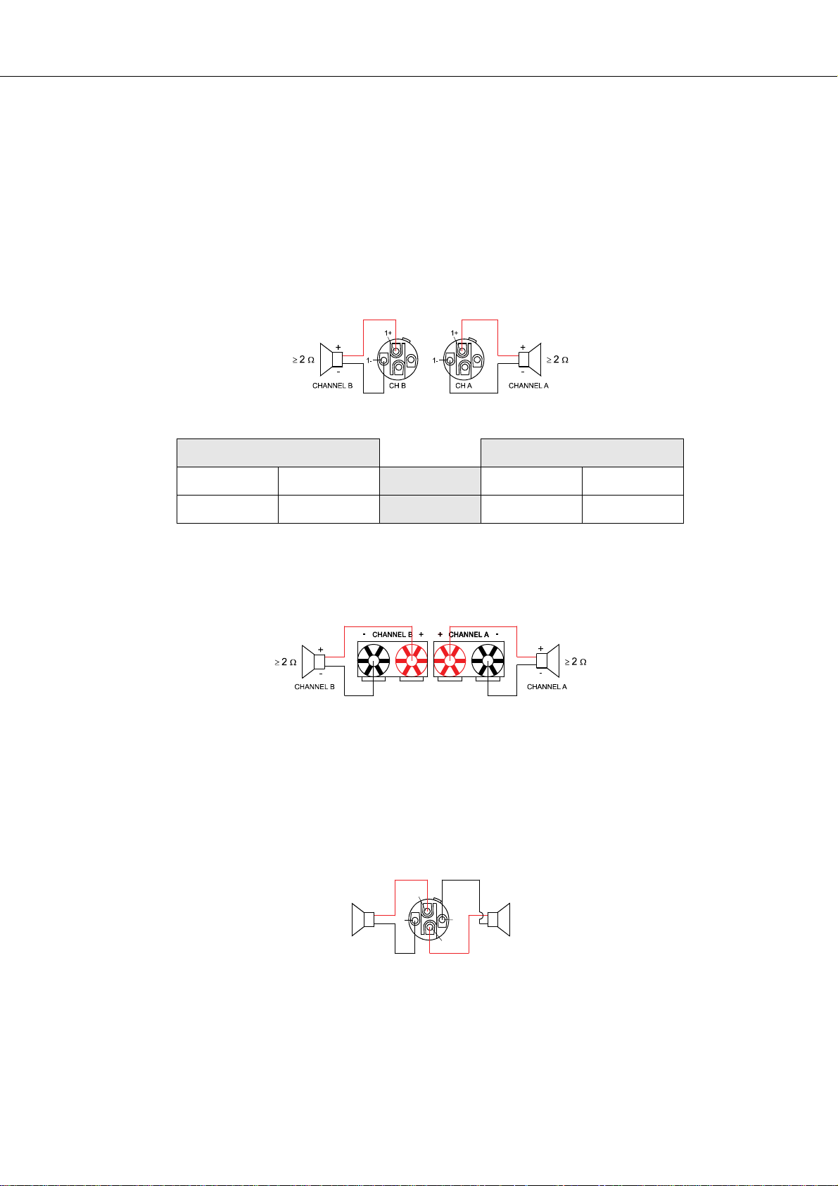
Bi-Amp Cabling
The second possibility for connecting the speakers when the power amplifier is operated in NORMAL
mode is to only use the Speakon-type connector CH A and to connect one speaker cabinet to pins 1+ and
1–, as described above and the second cabinet to pins 2+ and 2– as shown in illustration 2.15. Only pins
2+ and 2– of the Speakon CH A connector are assigned. Proceeding like this facilitates the cabling of
speaker systems that are used in active 2-way operation (Bi-Amp).
1+
+
≥ 2 Ω≥ 2 Ω
1-
-
2+
CH ACHANNEL A CHANNEL B
+
2-
-
Illustration 2.15: Bi-Amp speaker connection in NORMAL operation mode, using only the Speakon A con-
nector
Owner’s Manual 17
Page 18
PowerH SERIES
Speakon CH A
Connection Pin 1+ 1- 2+ 2-
Channel Assignment A+ A- B+ B-
Table 2.6: Bi-Amp speaker connection in NORMAL operation mode, using only the Speakon A connector
Output (Speakon-type Connectors / Terminals) in Bridged Mode
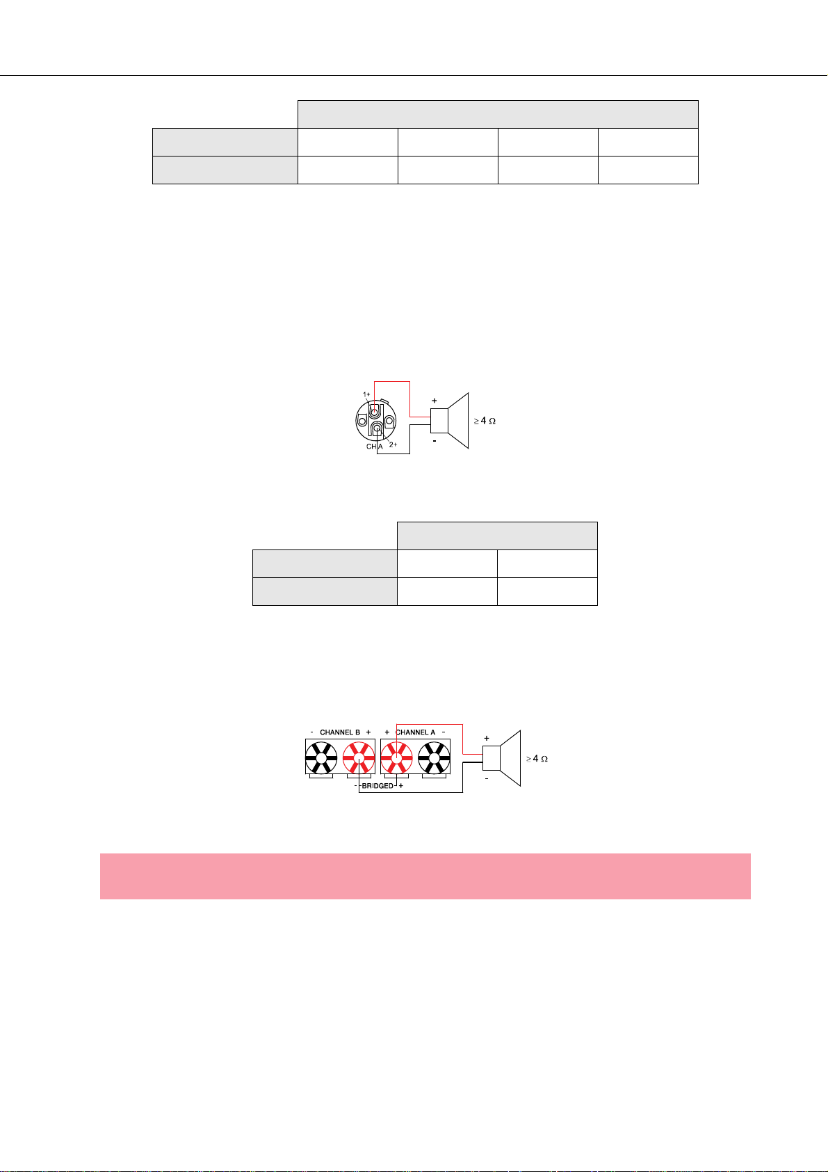
Setting the MODE switch on the power amp’s rear panel to BRIDGED lets the power amplifier run in
bridged mode operation and speaker connection has to be established using pins 1+ and 2+ of the
Speakon socket CH A, see illustration 2.16.
Illustration 2.16: Speaker connection in BRIDGED operation mode, using Speakon A
Speakon CH A
Connection Pin 1+ 2+
Channel Assignment Bridged+ Bridged-
Table 2.7: Speaker connection in BRIDGED operation mode, using Speakon A
When using the speaker terminals in BRIDGED mode, the loudspeaker system has to be connected to the
red terminals of CHANNEL A and CHANNELB. An illustration of how to correctly establish speaker
connection for this mode of operation is provided on the power amp’s enclosure.
Illustration 2.17: Speaker connection in BRIDGED operation mode, using Terminals
CAUTION:
Due to the high current, using banana plugs for speaker connection is not permissible.
18 Owner’s Manual
Page 19
PowerH SERIES
3 Operation
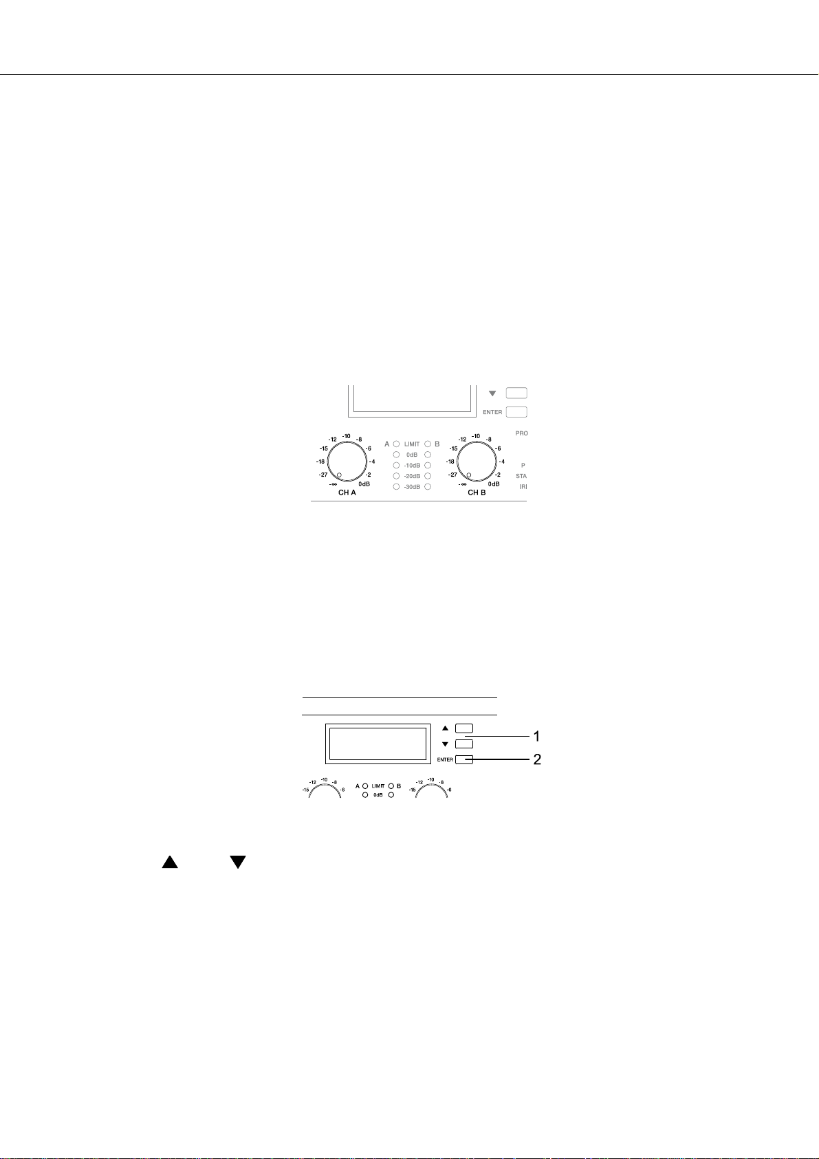
3.1 Volume Control
In DUAL and PARALLEL mode, the level controls CH A and CH B on the power amp’s front panel are used
to control the amplification of the corresponding channel. Turning the control to the right increases and
turning it to the left decreases the volume. In BRIDGED mode operation, the output volume of the power
amp is only controlled by the CH A level control. Any changes in the setting of the CH B level control are
ignored.
With an installed remote control module, the level controls CH A and CH B may be deactivated, i.e.
controlling the power amp’s amplification is only possible via IRIS-Net™. The Level Controls Off !
indicator on the LC display signals that the controls are deactivated.
Illustration 3.1: Level controls CH A and CH B
3.2 Graphical LC display
The graphical LC display provides detailed information about the operating status of the power amplifier.
Furthermore, it is possible to change several settings of the power amp and, if installed, of a remote control
module.
Illustration 3.2: LC display with controls
1
Up / Down buttons: These keys allow navigating through the menu.
ENTER button: Pressing this key selects the highlighted menu entry.
2
Owner’s Manual 19
Page 20
PowerH SERIES
Power Amplifier Menu Navigation
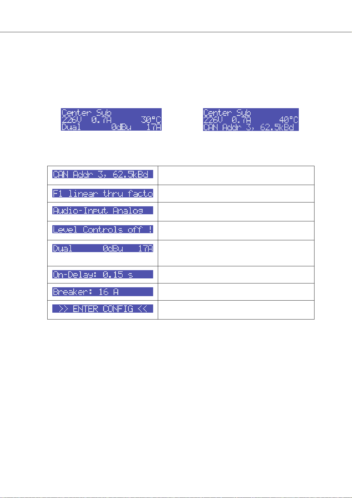
Start screen and type designation appear after switching the power amplifier on. The power amp’s status
display appears after a few seconds. The top line always shows the name of the power amplifier. An
overview of the power amp’s actual condition is provided in lines two and three. Flashing values in line 2
indicate reaching the limit of the permissible operating range. Additional information is shown if, for
example, a RCM-26 has been installed in the power amplifier.
Illustration 3.3: Status display of the power amplifier without / with RCM-26 installed (example)
Using the Up/Down buttons lets you scroll through the bottom line. The following table lists the information,
which is displayed in consecutive order.
Set CAN address and CAN baud rate (only with RCM-26
installed)
Name of the actual preset (only with RCM-26 installed)
Currently used audio input of the power amp (only with
RCM-26 installed)
Status of the input level controls on the power amp’s front
panel (only with RCM-26 installed)
Currently active parameters for the mode of operation,
sensitivity and Mains Circuit Breaker Protection (only with
RCM-26 installed)
Power-on delay of the power amp
Actual parameter for the Mains Circuit Breaker Protection
Pressing the ENTER button branches to the CONFIG con-
figuration menu.
Table 3.1: Overview status display
20 Owner’s Manual
Page 21
PowerH SERIES
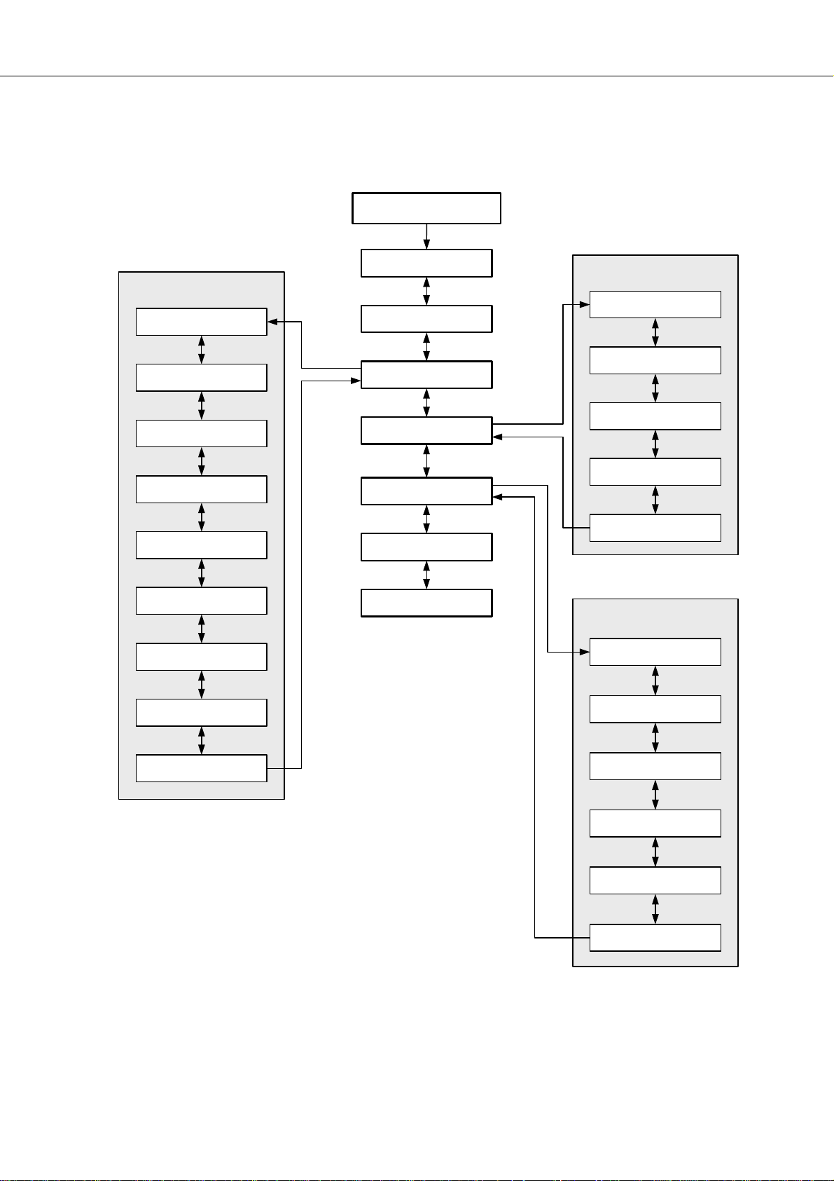
The following illustration shows the structure of the CONFIG menu (and its associated submenus) when
opening it from the status display. Menu entries marked with an asterisk * are only available when the
remote control module is not installed.
Status display
EVENT LOG
Counter POWER UP
Counter AMP ON
Counter PROTECT
Counter AMP MUTE
Counter MAINS FAIL
Uptime
Show Event History
Power-On-Delay
Breaker Current
Show Event Log
Menu Display
Menu Service
Amplifier Name*
EXIT
DISPLAY SETUP
LCD Contrast
LCD Brightness
LCD Time to Dim
Temperature Unit
BACK
SERVICE
Restore Amplifier’s
Factory Settings
Reset Event Log
BACK
Lifetime
Last Log
Module Signature
Firmware Version
BACK
Illustration 3.4: The power amp’s menu structure
Owner’s Manual 21
Page 22

PowerH SERIES
Structure of the CONFIG menu
Entering the CONFIG menu is possible through pressing the ENTER button while the entry >> CONFIG <<
is highlighted in the status display. The following provides detailed information about the individual items of
the configuration menu.
CONFIG/Power-On-Delay: The power amp’s currently set poweron delay is shown. Pressing the ENTER-Taste button opens the
Set Power-On-Delay dialog box.
Using the Up/Down buttons in the Set Power-On-Delay lets
the user specify a delay in the range of 0 seconds to up to 6.35
seconds. Pressing the ENTER button again stores the previously
made setting and the display returns to the CONFIG menu.
CONFIG/Breaker Current: The actually set value of the current
that controls the Mains Circuit Breaker Protection is displayed.
The set current has to match the value of the power amp’s internal
fuse for the protection to work correctly. Please refer to the
explanations on page 32 for more details. Pressing the ENTER
button opens the Set Breaker Current dialog box where the
desired value for the breaker current can be set.
The valid value ranges depend on the power amp’s power supply.
Currents between 6 A and 40 A can be set when the power
amplifier is operated at 120 V. Currents between 6 A and 30 A can
be set when the power amplifier is operated at 220-240 V. Select
Factory 30 A or Factory 16 A for automatic setting
depending on the power amp’s power supply. Pressing the ENTER
button stores the selected current value in memory and the
CONFIG menu reappears on the display.
NOTE:
Operating the power amplifier on a separately fused mains power line is recommended
only.
CONFIG/Show Event Log: The menu entry Show Event Log
leads to the EVENT LOG submenu. The individual entries in the
EVENT LOG menu are explained in detail in the paragraph
Structure of the CONFIG.EVENT LOG menu (see page 23).
CONFIG/Menu Display: The menu entry Menu Display leads to
the DISPLAY SETUP submenu. Each entry in the
DISPLAY SETUP menu is explained in detail in paragraph
Structure of the CONFIG/DISPLAY SETUP menu (see page 24).
22 Owner’s Manual
Page 23
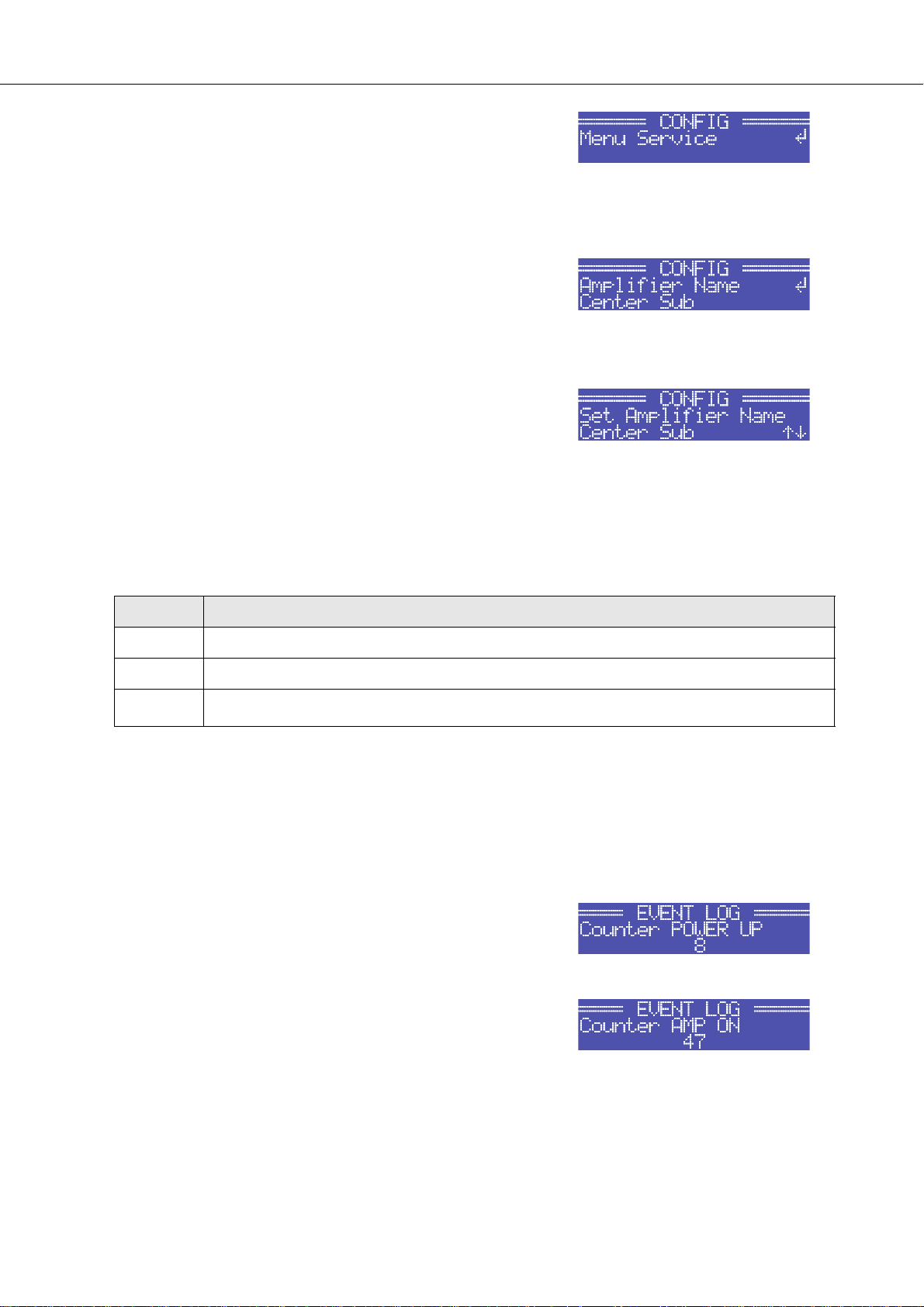
CONFIG/Menu Service: The menu entry Menu Service
branches to the SERVICE submenu. The entries in the SERVICE
menu are explained in detail in paragraph Structure of the
CONFIG/SERVICE menu (see page 26).
CONFIG/Amplifier Name: Displays the name of the power
amplifier. The menu entry only exists when no RCM-26 is installed
in the power amplifier. With a remote control module installed, the
power amplifier has to be named via IRIS-Net™. Pressing the
ENTER button opens the Set Amplifier Name dialog box.
The Set Amplifier Name dialog allows changing the power
amp’s name, which can be composed of a maximum of 20
symbols and consist of all letters a-z, A-Z, the numbers 0-9 and
special characters.
Pressing the Up/Down buttons locates the cursor at the desired
position of the name. Pressing the ENTER button accepts the
desired symbol and moves the cursor to the next character.
Pressing the ENTER button after manipulating the last character,
stores the desired name of the power amplifier in the memory and
the display returns to the CONFIG menu.
PowerH SERIES
The following special characters provide special functions when entering a power amp’s name:
Character Function
↵ Accepts the entered name and returns to the menu.
A
I
Deletes the currently selected symbol and moves the cursor by one character to the right.
Set the cursor by one character to the left.
Table 3.2: Functions of special characters when entering the power amp’s name
Structure of the CONFIG/EVENT LOG menu
CONFIG/EVENT LOG/Counter POWER UP: This menu item
shows how many times the power switch on the front panel has
been used.
CONFIG/EVENT LOG/Counter AMP ON: This menu item shows
how often the power amplifier has been activated from the OFF or
STANDBY state.
Owner’s Manual 23
Page 24
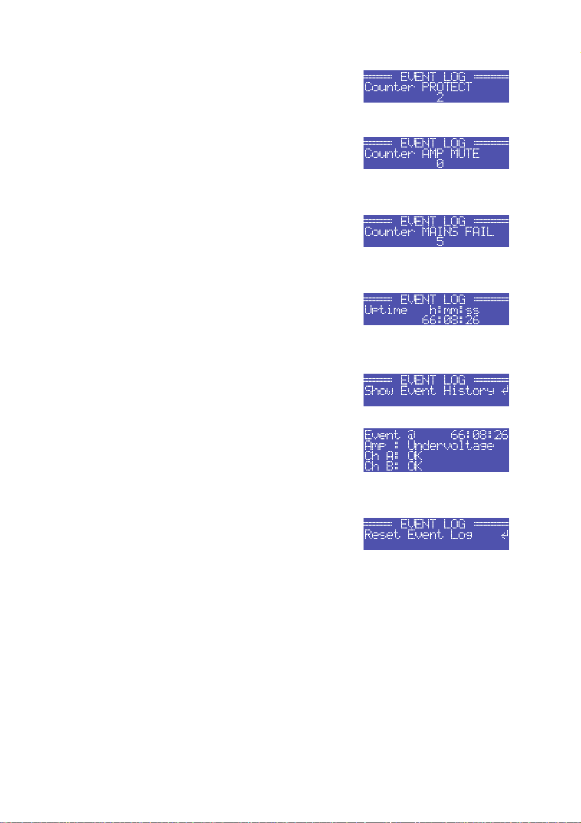
PowerH SERIES
CONFIG/EVENT LOG/Counter PROTECT: This item shows how
many times one of the protections has been activated.
CONFIG/EVENT LOG/Counter AMP MUTE: This menu item
shows how often the power amp’s output signal has been muted by
one of the protections.
CONFIG/EVENT LOG/Counter MAINS FAIL: This menu item
shows how many times over- or undervoltage has been recognized
at the power amp’s power supply unit.
CONFIG/EVENT LOG/Uptime: This menu item shows the total
running time of the power amplifier (not counting standby times)
since the last reset of the Event Log.
CONFIG/EVENT LOG/Show Event History: The Show Event
History menu entry opens a list of all events in chronological order
(last event shown first) that have been registered. Pressing the
ENTER button selects the desired item in the list.
Point in time and cause of the occurrence is shown for each item
in the list. The state of operation of the amplifier (Amp) and the two
output channels (Ch A or Ch B) is indicated for each event.
Pressing the Up/Down buttons lets the user scroll through the list
of entries. Pressing the ENTER button lets one return to the
CONFIG. menu.
CONFIG/EVENT LOG/Reset Event Log: The user can completely
reset the Event Log of the power amplifier in this menu entry. All
counters are reset to zero and the event log is deleted. Pressing
the ENTER button opens a safety dialog box that lets the user
choose between YES or NO by pressing the Up/Down buttons. If
YES has been selected, pressing the ENTER button resets the
Event Log. If the user decides to select NO, the Event Log stays
unchanged and the CONFIG. menu reappears on the display.
24 Owner’s Manual
Page 25
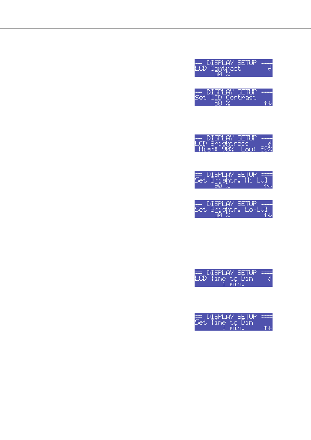
Structure of the CONFIG/DISPLAY SETUP menu
CONFIG/DISPLAY SETUP/LCD Contrast: This menu item
indicates the currently set contrast of the LC display. Pressing the
ENTER button opens the Set LCD Contrast where the user
can select a contrast setting in the range of 0 % to 100 % by using
the Up/Down buttons. Pressing the ENTER button again stores
the selected value for contrast in memory and the CONFIG menu
reappears on the display.
CONFIG/DISPLAY SETUP/LCD Brightness: The currently set
maximum and minimum values for display brightness are
indicated. The maximum value represents the brightness of the
display that is used during normal operation. The minimum value
represents the brightness of the display that it is adjusted to after a
specific period of time, if desired.
PowerH SERIES
Pressing the ENTER button opens the Set Brightn. Hi-Lvl
dialog box, which, by pressing the Up/Down buttons, allows
setting the undimmed display brightness in a range of 50 % to
100 %.
Pressing the ENTER button stores the set brightness value in
memory and the display indication changes to the
Set Brightn. Lo-Lvl dialog box, where pressing the Up/
Down buttons allows setting the dimmed display brightness in a
range of 0 % to 80 %. Pressing the ENTER button again stores
the set brightness value and the display returns to the CONFIG.
menu.
CONFIG/DISPLAY SETUP/LCD Time to Dim: The currently set
time interval, during which the display lights with the maximum
brightness it has been set to, is indicated. After the time interval
has expired the display is dimmed.
Pressing the ENTER button opens the Set LCD Time to Dim
dialog box, where the user can specify the duration after which the
display dimming starts by pressing the Up/Down buttons. The
duration can be set to 4, 8, 16, 32 or 64 minutes. Alternately, the
user can select Autodim off to completely deactivate the
dimming function, which results in the display always lighting at
the set maximum brightness level (Brightn. Hi-Lvl).
For an increased lifetime of the display, activating the dimming
function is recommended. Pressing the ENTER button stores the
settings in memory and the display returns to the CONFIG menu.
Owner’s Manual 25
Page 26
PowerH SERIES
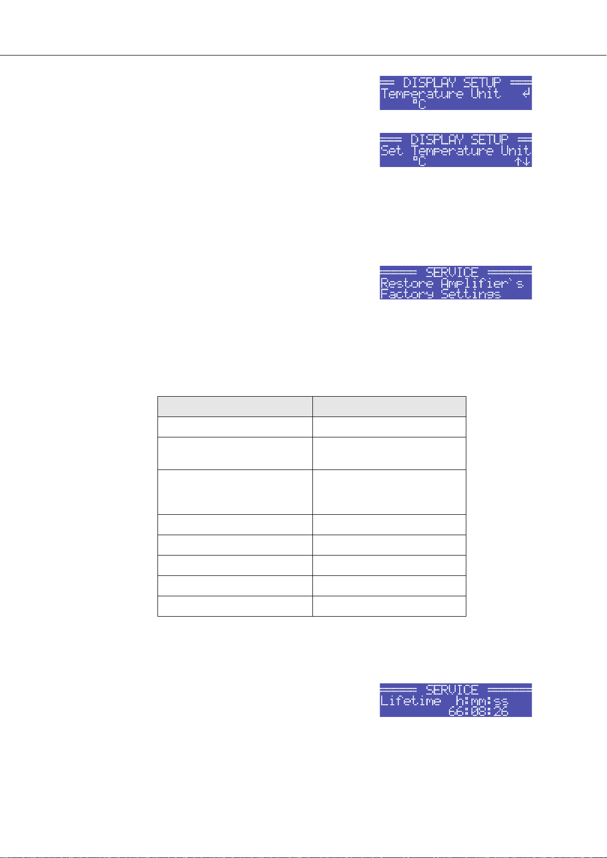
CONFIG/DISPLAY SETUP/Temperature Unit: The currently
selected unit for the indication of temperature values is displayed.
Pressing the ENTER button opens the Set Temperature Unit
dialog box, which allows selecting °C (Degrees Celsius) or °F
(Degrees Fahrenheit) by pressing the Up/Down buttons. Pressing
the ENTER button stores the selected unit in memory and the
CONFIG menu reappears on the display.
Structure of the CONFIG/SERVICE menu
CONFIG/SERVICE/Restore Amplifier’s Factory Settings: The
power amplifier can be reset to factory settings. Pressing the
ENTER button opens a safety dialog box that lets the user choose
between YES or NO by pressing the Up/Down buttons. If YES has
been selected, pressing the ENTER button resets the power
amplifier to its factory settings. If the user selected NO, all power
amp parameters stay unchanged and the display returns to the
CONFIG. menu.
The following table lists all parameters that are affected by a reset:
Parameter Value
Power-On-Delay 0.00 s
Breaker Current (depends on
the supply voltage)
Amplifier Name Dynacord H2500
LCD Contrast 50 %
LCD Brightness High 90 %
LCD Brightness Low 40 %
LCD Time to Dim Autodim off
Temperature Unit °C
Table 3.3: Factory settings of the LC display
16 A (230 V) / 30 A (120 V)
Dynacord H5000
or
CONFIG/SERVICE/Lifetime: This menu item shows the total
running time of the power amplifier (not counting standby times).
26 Owner’s Manual
Page 27
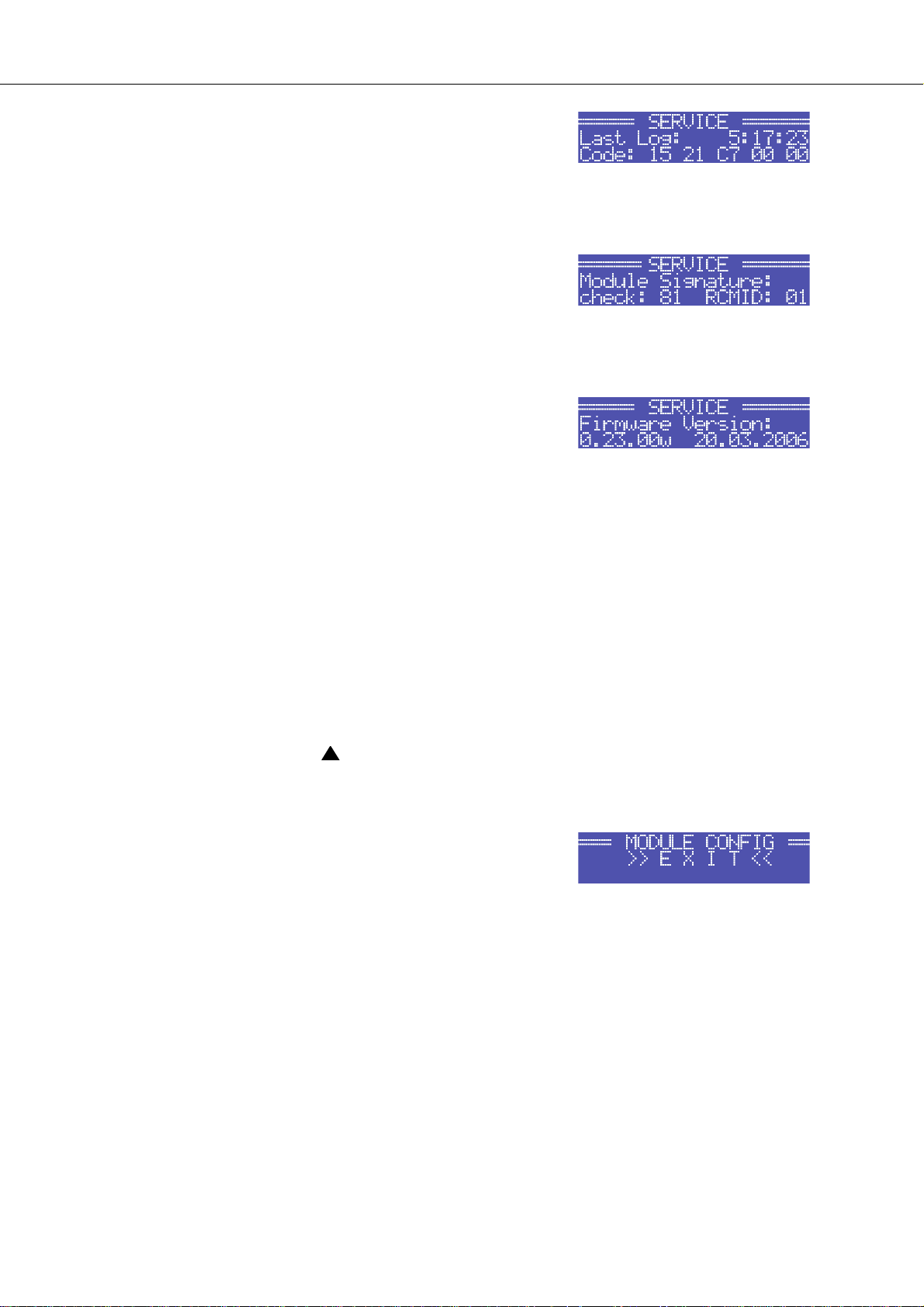
CONFIG/SERVICE/Last Log: Shows point in time and type of the
last entry in the event history. If service is needed, the code shown
here provides relevant detail of what might have caused the
malfunction for your Dynacord Service partner.
CONFIG/SERVICE/Module Signature: In the event of failure or
malfunction, the information shown here provides relevant detail of
what might have caused the malfunction for your Dynacord Service
partner.
CONFIG/SERVICE/Firmware Version: This menu item shows
version and date of the firmware that is actually installed in the
power amplifier.
PowerH SERIES
Structure of the MODULE CONFIG menu
The MODULE CONFIG menu provides access to RCM-26 remote control module settings, which are
available from the LC display of the power amplifier. This menu cannot be accessed during operation of
the power amplifier. Accessing this menu is only possible when the power amp is switched off.
The following steps open the MODULE CONFIG menu:
1. If the power amplifier is powered on or in standby mode, use the mains switch on the front panel to
switch the power amp off.
2. Simultaneously press the and ENTER buttons and keep them pressed.
3. Use the power switch on the front panel to switch the power amplifier on.
The power amp enters standby mode and the MODULE CONFIG
menu appears on the display.
Owner’s Manual 27
Page 28
PowerH SERIES
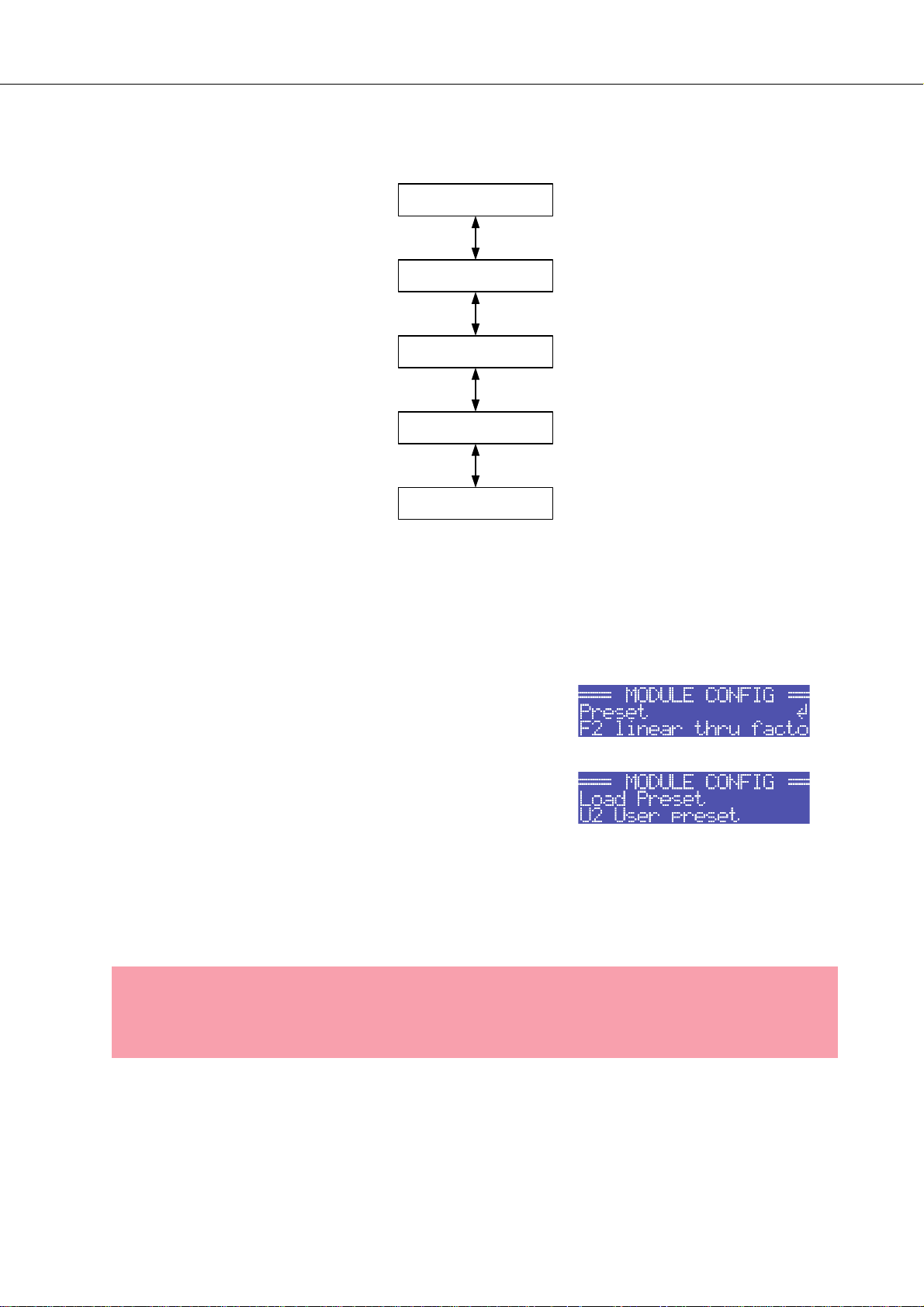
Illustration 3.5 shows the structure of the MODULE CONFIG menu of a PowerH SERIES amplifier
with an installed RCM-26 remote control module.
EXIT
Preset
CAN-Baudrate
Audio-Input
Power
Illustration 3.5: Structure of the Module Config menu (RCM-26)
The following provides detailed information about the individual items of the MODULE CONFIG menu.
MODULE CONFIG/Preset: The name of the currently active
preset is displayed. Pressing the ENTER button opens the
Load Preset dialog box, which allows the user to select a preset
by pressing the Up/Down buttons.
Pressing the ENTER button opens a safety dialog box, which lets
the user select whether he actually wants to load the selected
preset by pressing the Up/Down buttons to either select YES or
NO. When YES has been selected, pressing the ENTER button
loads the selected preset and the display returns to the MODULE
CONFIG menu. When NO has been selected, the selected preset
is not loaded. The power amp’s currently active preset is not
changed and the MODULE CONFIG menu reappears on the
display.
CAUTION:
The selected preset must be suitable for the use with the connected loudspeaker components. A incorrectly adjusted preset or incompatible preset can cause serious damage
to the connected speaker systems.
28 Owner’s Manual
Page 29
PowerH SERIES
MODULE CONFIG/CAN-Baudrate: The currently set CAN baud
rate of the RCM-26 is being indicated. Pressing the ENTER button
opens the Set CAN-Baudrate dialog box, which by pressing the
Up/Down buttons, lets the user select one of the following CAN
baud rates: 10kBaud, 20kBaud, 62.5kBaud, 125kBaud,
250kBaud or 500kBaud.
Pressing the ENTER button stores the selected baud rate in
memory and the display returns to the MODULE CONFIG menu.
CAUTION:
All devices on a specific CAN-BUS must be set to the same baud rate.
MODULE CONFIG/Audio-Input: The currently used audio input
is indicated. Pressing the ENTER button opens the
Select Audio-Input dialog box, which, by pressing the Up/
Down buttons, allows selecting Analog or AES/EBU inputs.
Pressing the ENTER button stores the desired input in memory
and the display returns to the MODULE CONFIG menu.
MODULE CONFIG/Power: The power amp’s actual operating
status after using the mains switch is displayed.
If standby mode has been activated via IRIS-Net™ and the power
amplifier has been switched off using the mains switch, the power
amp automatically restarts into standby mode the next time it is
switched on by pressing the mains switch. This menu item allows
booting the power amplifier out of standby mode, even without
IRIS-Net™.
Pressing the ENTER button opens the Set Power dialog box,
which allows the selection of On or Standby operating states by
pressing the Up/Down buttons. Pressing the ENTER button stores
the desired status in memory and the MODULE CONFIG menu
reappears on the display.
Owner’s Manual 29
Page 30

PowerH SERIES
3.3 Indications
PROTECT
Whenever the PROTECT-LED lights yellow, one of the internal protections has been activated. However, a
lit PROTECT-LED does not necessarily mean that the signal path gets switched off. The differentiated
protections concept of PowerH SERIES power amps results in several protection circuits being
activated one after another, which ensures that under normal circumstances the power amplifier will stay in
the safe and stabile operating range. In case the amplifier needs to be switched off to prevent power
amplifier and connected speaker systems from being damaged, this is indicated by the PROTECT and
MUTE-LEDs being lit simultaneously.
MUTE
The MUTE-LED lights red whenever the power amp’s output signal is being muted, which happens for
example during power-on delay of the speaker systems, when switching the input sensitivity, and when
manually muting the output signal via IRIS-Net™.
-30dB…LIMIT
Level indication is realized via two vertical LED chains on the power amp’s front panel that individually
indicate the actual levels of each channel at -30dB, -20dB, -10dB below full modulation and 0dB as soon
as full modulation is reached. 0 dB indication results from comparing the power amp’s internal ratio of input
to output voltage, which ensures precise indication of the full modulation limit, even before limiting
becomes audible. If the input audio signal is driven above the 0 dB mark, a clipping limiter reliably controls
distortion down to a stable rate of 1 %. The red LIMIT-LED has a dynamic brightness control that makes it
easy to perceive the degree of limiting applied to the signal.
POWER
The POWER-LED lights green when the power amplifier is on. If the POWER-LED does not light, despite
the fact that the amplifier has been switched on, this indicates that the power amp is not connected to the
mains, the primary fuse has blown, or the amplifier is in standby mode (the STANDBY-LED lights yellow).
The POWER-LED blinks whenever the voltage at the MAINS IN is too high (overvoltage) or too low
(undervoltage), which prevents that the power amplifier can be switched on.
STANDBY
The STANDBY-LED lights yellow when the power amp is in standby mode. Standby mode reduces the
amp’s power consumption to an absolute minimum. Activating the standby mode is only possible via IRISNet™. Deactivating the standby mode is possible via IRIS-Net™ as well as directly on the power amplifier.
For deactivating the standby mode, select Power from the Module Setup menu (see page 29).
30 Owner’s Manual
Page 31

PowerH SERIES
IRIS-Net
The IRIS-Net-LED lights blue if an IRIS-Net™-compatible remote control module has been installed in the
power amp’s extension slot and successful data communication has been established. The IRIS-Net-LED
blinks slowly whenever the “Find” function in IRIS-Net™ is being used to locate a power amplifier in the
rack. All other LEDs are deactivated during this time.
3.4 Fan Cooling
The power amplifier has two fans on the front and one on the rear. The fans are switched in five
performance-optimized levels, i.e. they are not running permanently but the running speed of each fan is
individually controlled depending on the ambient temperature. That in return ensures very silent running
during idle state. The temperatures of the power amp’s two channels and of the power supply unit are
registered and monitored separately. The intelligent and processor-controlled fan-control activates a fan to
run exactly at the level that is needed to cool down the corresponding components. This concept
effectively prevents the needless "rev up" of the fans when in idling state as well as the occurrence of a
thermally balanced condition, which causes permanent noise-intensive running of the fans. In other words,
the fans are activated only when it is really necessary because of thermal conditions. During power-on of
the amplifier, all fans run for a short period of time to verify the correct functioning.
3.5 Air Filter
An unrestricted airflow inside of the power amplifier is important for trouble-free operation. This is achieved
through conducting the airflow through cooling tunnels. This optimized routing of airflow has the effect that
in most cases the installation of air filters is not necessary. Installing air filters is only recommended when
using the power amp in an environment where dust exposure is excessively high. With air filters installed,
make sure to regularly check the filters for dust deposit and, if necessary, clean or replace them to protect
the power amplifier against thermal stress and consequently to prevent activation of the Thermal
Protection.
Owner’s Manual 31
Page 32

PowerH SERIES
3.6 Protections
In case one of the power amp’s internal protections responds during operation, a corresponding message
appears on the LC display (or the PROTECT-LED lights) and an entry containing date, time, and protection
type is created in the event log.
True RMS Mains Voltage and Current Measurement
PowerH SERIES amplifiers are consistently informed about the state of the mains network that they
are connected to. The CPU of the power amplifier continually computes the current RMS (Root Mean
Square, effective value) of the mains voltage and the mains current consumption. This genuine RMS
measurement has substantial advantages over the commonly used peak value measurement:
• Mains voltage measurement functions reliably even with non-sinusoidal mains networks, which, for
example, can be found with a generator-powered amplifier or when the mains voltage situation becomes unstable.
• Mains voltage measurement is insusceptible to transient mains interference, as can occur when swit-
ching inductive loads such as large electric motors.
• True mains current RMS measurement allows the precise matching of the power consumption to the
characteristics of a mains circuit breaker. Detailed information about the adjustable Mains Circuit Brea-
ker Protection function is provided in the following paragraph.
RMS measurement permanently protects the power amplifier against mains over or undervoltage. At the
occurrence of extreme mains overvoltage, the power amp switches off to prevent severe damage.
Switching on the power amp is not possible whenever mains overvoltage has been detected. The mains
voltage monitoring protection switches the power amplifier off at the occurrence of extreme mains
undervoltage (less than 70 V AC). In both cases, the blinking POWER-LED indicates the fault condition. In
case of power outage, both output channels are instantly muted then the power amplifier is shut down
within only a few milliseconds.
Mains Circuit Breaker Protection
The power amplifier automatically reduces the output power whenever it is driven at high levels with
extremely low-impedance loads connected resulting in the chance that the mains circuit breaker reacts.
Therefore, adjusting the characteristics of the utilized circuit breaker in Amperes is possible via the LC
display. Especially at extremely high/low ambient temperatures or when connecting the power amplifier
together with other equipment to a single common automatic circuit breaker, it might become necessary to
manually set an Ampere value that differs from the circuit breaker’s nominal value to ensure that the Mains
Circuit Breaker Protection functions optimally. The following table outlines the allowable value ranges and
default settings for the two modes of operation at 120 V and 220-240 V.
Operation Minimum Maximum Factory Settings
120 V 6 A 40 A 30 A
220-240 V 6 A 30 A 16 A
Table 3.4: Mains Circuit Breaker Protection
32 Owner’s Manual
Page 33

PowerH SERIES
The power amp’s CPU is acquainted with the temporal progression of the mains current consumption and
therefore can simulate the typical behavior of a mains circuit breaker. Nevertheless, pulse peaks allow
crest currents that can exceed the nominal value by a multiple. RMS measurement of the mains current
consumption allows the CPU to emulate the temperature curve of a circuit breaker’s thermal trip, which in
return enables the Mains Circuit Breaker Protection to let the power amplifier work till shortly below the
trigger level of the automatic circuit breaker. With typical concepts, especially for those without RMS
current measurement, output power reduction has to be applied much earlier. During the processing of
musical program material, the Mains Circuit Breaker Protection normally does not have to reduce the
power amp’s output power. At most, with settings that are noticeably below the pre-set values of 16 A or 30
A respectively, (which may be reasonable when operating multiple power amps via a single automatic
circuit breaker) output power reduction might become necessary to prevent the mains fuse from blowing.
Power-On Delay and Softstart
A Power-On Delay of up to 6.35 seconds can be programmed for the power amp via the LC display. Upon
pressing the mains switch the power amplifier does not start until the set delay time has elapsed. If several
power amps are operated on the same automatic circuit breaker, cascaded switch-on can be accomplish
by programming individually different power-on delays for the amps. This also prevents the magnetic trip of
an automatic circuit breaker from acting and thus disconnecting the power amplifiers from the mains
supply, when various amps are switched on at the same time. The internal soft-start function additionally
suppresses current peaks during power-on, which ensures trouble-free operation of PowerH
SERIES amplifiers even on very sensitive automatic circuit breakers.
Output Short Circuit Detection
The corresponding output voltage and output current is measured for both output channels as soon as the
power amplifier processes an audio signal. These readings are used to monitor the connected
loudspeaker loads. The power amplifier has the ability to continuously deliver very high output currents.
For example, if, in spite of a low output voltage, the current flow is high as the consequence of a shortcircuit in one of the speaker lines, the power amp detects this fault condition and immediately disables
signal output to protect connectors and cables against damage from overload. This, of course, also
protects the power amplifier itself from being damaged by excessive electrical or thermal overload.
Advanced Thermal Protection
The PowerH SERIES amplifiers are the first to feature the new Advanced Thermal Protection
(ATP). This new system differs in a trend-setting manner from traditional thermal protection measures,
which, as soon as the fans are not any longer capable of dissipating the lost heat, mostly switch off the
entire signal path at a relative early stage. With the ATP system switching off the signal path is last of three
consecutive measures. Prior to making this final step, the system uses two other approaches to limit the
amp’s power, so that it returns to a thermally stable operational range.
The first step is Voltage Limitation. This measure reduces the internal supply voltage of the power amplifier
blocks, which, objectively, is at the expense of reducing the voltage dynamic. During the reproduction of
music or speech, however, this effect is subjectively hardly perceived. Despite the negligible acoustic
influence, the efficiency gained in the power amp is so high that the development of heat is clearly
Owner’s Manual 33
Page 34

PowerH SERIES
reduced. As soon as the power amp’s temperature returns to a non-critical state, the ATP system
imperceptibly switches back to full supply voltage.
Thermal Limiter is the second measure that is only activated if, under extreme conditions, Voltage
Limitation is not sufficient. The thermal limiter circuit unobtrusively reduces the amplification of the power
amplifier. Only if even this measure does not re-establish thermal balance, the ATP system activates
Thermal Mute as the last step to completely switch off the signal path.
This step-by-step functioning of Advanced Thermal Protection enables PowerH SERIES amplifiers
to still be in operation under conditions where various other amps would have ceased operation.
The PROTECT-LED lights immediately to signal any direct intervention in the signal path by limiters and a
corresponding indicator in IRIS-Net™ allows the FOH-engineer to react instantly, even before interference
with the audio performance becomes noticeable.
Monitoring Ambient Temperature
PowerH SERIES amplifiers constantly monitor the temperature of several active electrical
components during operation. In addition, monitoring also includes the temperature of the inlet cooling air
and as a result also the temperature of the power amp’s ambience. If, for any reason the ventilation
louvers are totally blocked or the inlet outer air exceeds the upper temperature limit for effective cooling,
this would inevitably lead to overheating of the power amplifier. This condition can possibly occur even
when the power amplifier is in idling mode, for example when it is installed in a closed rack case.
However, during idling the preventive measures of the Advanced Thermal Protection (see previous
paragraph) show hardly any impact. For this reason the power amplifier enters standby mode once it is
operated under extreme thermal load, which is caused by inadequate cooling. In that case, PROTECTLED and STANDBY-LED blink alternately.
The power amplifier automatically re-starts after approximately 20 minutes. As an alternative, re-starting
the power amplifier manually using the mains switch or via IRIS-Net™ is also possible, if the device has
cooled down sufficiently.
HF-Limiter
If the power amplifier processes high-frequency signals at high levels, amplification is automatically
reduced after a while to protect the output stages against damage. Most of the time such conditions result
from a malfunction in one of the devices that are connected upstream in the signal chain. The situation
becomes particularly critical for power amplifier and connected tweeter cabinets when the signal is still in
the audible range or just above the auditory threshold. Conventional HF-Protection circuits are not
sensitive enough to react within this particular range, since they are primarily targeted at detecting fault
conditions of the power amplifier itself.
Next to conventional HF-Protection, PowerH SERIES amplifiers have also a HF-Limiter, which is
frequency-dependent and permanently monitors the output signal. The HF-Limiter possesses the ability to
reliably differentiate between normal reproduction of music and speech and critical operating conditions.
The power amp’s signal amplification is automatically reduced whenever such a critical operating condition
occurs.
34 Owner’s Manual
Page 35

PowerH SERIES
4 Options
Installing one of the optionally available extension modules in the extension slot on the rear panel lets you
expand the power amp’s functional range. As an example, the following paragraphs describe all aspects of
the RCM-26 Remote Control Module in detail. Please read and follow the instructions provided in the
owner’s manuals that you have received together with each extension module.
4.1 RCM-26
System Description
The RCM-26 Remote Control Module is a two-channel digital controller module for live sound
reinforcement, PA and fixed installation applications. Installing the RCM-26 turns a conventional amp into a
remote amplifier, which, at any time, provides complete overview of the overall system status and control
of all system parameters.
RCM-26 modules allow the integration of PowerH amplifiers into a remote control network with up to
250 units. This offers the possibility to control and monitor an entire PA system from one or more PCs
using the IRIS-Net™ - Intelligent Remote & Integrated Supervision - software package. All operational
states, e.g. power-on status, temperature, modulation, limiting, activation of protections, deviation from the
load impedance, etc., are centrally registered and displayed in IRIS-Net™. This provides the possibility to
react and to selectively intervene even before critical operational states arise. Programming an automatic
reaction, when specific thresholds are being exceeded or fallen below, is also possible.
With an RCM-26 installed, the integrated impedance testing function allows very precise monitoring of the
connected loudspeaker systems. The impedance testing function utilizes the internal test tone signal
generator and voltage/current measuring to determine the impedance of the loudspeaker systems
including crossovers and cables over the entire frequency range. IRIS-Net™ plots an impedance curve of
the measured impedance that can be compared with a formerly stored reference curve at any time. This
reveals even smallest loudspeaker defects or deficiencies instantly. The impedance testing function is
optimized for low impedance loads, like typical loudspeaker cabinets and/or loudspeaker components.
All parameters, like power on/off, level, muting, filters, etc. can be controlled in real-time and stored in the
amplifier. Besides controlling and monitoring amplifiers, the RCM-26 also offers all conventional signal
processing functions, like parametric equalizers, frequency crossovers, delays, compressors and limiters.
Beyond that, linear-phase FIR-filters, zero-latency FIR-filters and digital speaker protection algorithms are
available to optimize the amplifiers and loudspeaker system. All DSP-settings can be freely edited and
stored in user presets directly on the module. In the event of network failure or loss of power, all settings
(filters, delay, level, etc.) stay intact, independent of the control by the network.
Furthermore, the RCM-26 provides a control port with freely programmable control inputs and control
outputs. Control inputs (GPI's) allow the connection of switches. IRIS-Net™ offers the possibility to
program a variety of logic functions for the inputs (e.g. switching to an alarm-preset with maximum energy
in the speech area). Control outputs (GPO's) allow the connection of external components, which, for
example, are used to signal specific states to peripheral equipment. Consequently, an amplifier with a
RCM-26 module installed corresponds to highest safety requirements.
The RCM-26 has been designed with uncompromising audio quality in mind. Analog audio inputs
(internally) and an AES3 (AES/EBU) digital audio input with XLR-type connector are provided. The use of
Owner’s Manual 35
Page 36

PowerH SERIES
the digital audio input offers a dynamic range of 128 dB. Using the analog audio input offers a dynamic
range of 120 dB, which, by the way, is an absolute peak value for digital audio devices.
For further details about configuration, control and monitoring of amps with installed RCM-26 modules,
please refer to the documentation of the IRIS-Net™ software.
Installation Notes
1. Switch the power amp’s power off and pull the mains plug
2. Remove the cover panel from the rear panel (4 screws)
3. Insert the RCM-26 module in the slot and lock it in place on the rear panel using the 4 screws (see
illustration 4.1)
Illustration 4.1: Installation of a RCM-26
4. Set the module’s CAN-address using the ADDRESS selector switches
5. Connect the needed interfaces (CAN, Audio, Control Port, RS-232)
6. Reconnect the mains cord and switch on the power amplifier
7. The power amp automatically recognizes the installed RCM-26 module
IRIS-Net™
Configuring and controlling a remote amplifier
with a RCM-26 module installed is possible
through the use of IRIS-Net™ (Intelligent
Remote & Integrated Supervision) PC-software.
IRIS-Net™ allows programming the RCM-26
module’s complete configuration while the
computer is off-line. All instructions on how to
configure, operate and monitor all RCM-26
functions are included in the IRIS-Net™ help
files.
36 Owner’s Manual
Illustration 4.2: DSP flow diagram of the RCM-26
Page 37

Controls and Connections
PowerH SERIES
Illustration 4.3: Controls and Connections of the RCM-26
1 AES/EBU-IN
A digital AES/EBU input (AES3) is provided in addition to
internal analog inputs. The digital input signal has to be
connected to the AES/EBU IN connector. The AES/EBU
input is a balanced transformer-isolated input. A sampling
rate converter translates the input signal to match the
internal sampling rate. However, the possibility to
synchronize the RCM-26 to an external sampling rate exists
as well. For further details, please refer to the IRIS-Net™
help files. Illustration 4.4 shows the pin-assignment of the
input socket.
2 AES/EBU-OUT
The AES/EBU OUT connector allows looping-through the
digital audio signal to other RCM-26 modules. The digital
input signal gets internally buffered and preprocessed (level
matching / slew rate) before it is output via the OUTconnector. This allows fairly simple wiring between
modules, without the need for AES/EBU distribution amps
as they are usually used.
I l l u s t r a t i o n 4 . 4 : P i n - a s s i g n m e n t
of AES/EBU-IN
The RCM-26 has a bypass-relay, which, in case of damage
(e.g. power outage), connects the AES/EBU IN signal
through to AES/EBU OUT. This ensures trouble-free
operation of downstream remote amps.
I l l u s t r a t i o n 4 . 5 : P i n a s s i g n m e n t
of AES/EBU-OUT
Owner’s Manual 37
Page 38

PowerH SERIES
3 LOCK-LED
The LOCK-LED lights green as soon as the AES/EBU input has been synchronized to the
incoming signal and thus proper audio transmission has been established. The LOCK-LED is
dimmed with no digital audio signal being present at the input or the internal PLL not having
locked on to the incoming signal. The audio signal gets muted when the digital input has been selected.
4 REMOTE CAN BUS Connection
The RCM-26 module provides two Neutrik EtherCon® RJ-45 sockets for connecting to the REMOTE CAN
BUS. These sockets are connected in parallel and serve as inputs as well as for daisy-chaining the devices
on the remote network. Cabling in a rack system can be established using commercially available RJ-45
network cables. However, CAN guidelines have to be observed for longer cable lengths. Both ends of the
CAN-bus must be terminated using 120 Ω terminating plugs. For comprehensive information and
instructions on cabling and bus length, please refer to the “CAN Bus principles“ paragraph, starting on
page 41. Along with the CAN bus, network cabling also carries a balanced audio monitoring signal. This
monitor bus allows software-controlled monitoring of input or output signals of all power amps in the
remote network, without the need for additional wiring. Nominal output level is +6 dBu (1.55 V) and
maximum output level is +21 dBu (8.7 V). The CAN bus allows using different data rates, whereas the data
rate is inversely proportional to the bus length. For smaller network setups, data rates can be as high as
500 kbit/s. For broader networks, reducing the data rate becomes necessary (down to the minimum data
rate of 10 kbit/s). The following table illustrates the relation between data rate and bus length or network
size. The use of CAN repeaters is strongly recommended for busses that exceed 1000 meters in length.
Transfer rate (in kbit/s) Bus length (in m)
500 100
250 250
125 500
62,5 1000
20 2500
10 5000
Table 4.1: Transfer rate and bus length
Illustration 4.6: Pin-assignment of CAN jack
38 Owner’s Manual
Illustration 4.7: Pin-assignment of CAN plug
Page 39

PowerH SERIES
5 STATUS LED
The STATUS-LED is for monitoring the communication on the CAN bus. The LED blinks
rhythmically every 3 seconds, when the module’s address is set to “00“, which means that it
is disconnected from the CAN bus and software control. The LED blinks rhythmically in
intervals of one second, when an address in the range of 01 to 250 has been assigned to the
module and there has not yet been any activity on the CAN bus. As soon as communication
on the CAN bus is recognized, the LED lights for at least 100 ms, when the power amplifier
sends data on the CAN bus.
Pin Name
2 CAN_GND Green Orange
4CAN_H(+) Blue
5 CAN_L (-) Blue striped
7 MONITOR BUS + Brown striped
8 MONITOR BUS - Brown
Table 4.2: Overview CAN plug
T568A T568B
Colour
6 ADDRESS Selector Switch
The two address selector switches are for setting the network address of the RCM-26.
CAN networks support addresses in the range of 01 to 250 (FA hex). Addressing has to
be carried out in the hexadecimal number system. The LOW selector switch sets the
lower digit, while HIGH sets the higher digit.
CAUTION:
Each address may exist only onece in a system. Otherwise, network conflicts may arise
Address 0 (00 hex, delivery status) disables remote communication between the RCM-26 and the bus. The
module does not appear in the system, even though it is physically connected to the CAN-bus. Switching
on the power of an amplifier with an installed RCM-26 that has been assigned address 0 sets all its internal
parameters to 0 or bypass and the signal routing to 2-in-2. The power amplifier behaves absolutely linear,
i.e. signal processing is deactivated.
Owner’s Manual 39
Page 40

PowerH SERIES
HIGH LOW Address
0 0 Stand-alone
0 1...F 1...15
1 0...F 16...31
2 0...F 32...47
3 0...F 48...63
4 0...F 64...79
5 0...F 80...95
6 0...F 96...111
7 0...F 112...127
8 0...F 128...143
9 0...F 144...159
A 0...F 160...175
B 0...F 176...191
C 0...F 192...207
D 0...F 208...223
E 0...F 224...239
F 0...A 240...250
F B...F reserved
Table 4.3: CAN addresses
7 CONTROL PORT
The CONTROL PORT of the RCM-26 provides two control inputs, two control
outputs and reference connections for +5V and ground. The control inputs are
configurable via IRIS-Net™. They can be used for example for switching
between power on / standby modes, switching between presets or to control
parameters. The two control contacts IN1 and IN2 are internally connected via
pull-up resistors and carry +5V (open). The control inputs can be activated using
external switches, pushbuttons or relays to connect them to ground potential (pin 3). The two control
outputs OUT1 and OUT2 are open collector outputs, which are highly resistive in the non-active state (off).
In active state (on) the outputs are connected to ground. The control outputs are configurable via IRISNet™ and are used to signal internal states. LEDs, indicators or relays can be driven directly. The +5V
reference connector provides voltage supply for connected components.
CAUTION:
The maximally allowable current at the +5V output is 200 mA.
40 Owner’s Manual
Page 41

PowerH SERIES
8 RS-232 Interface
The RS-232 interface is for interconnecting the RCM-26 module and multi-media control systems or facility
management systems. All parameters can be controlled and queried via RS-232 interface. Communication
is realized through the use of ASCII-protocol. Implementation of this protocol is rather simple.
Programming notes and a complete protocol description are included in the IRIS-Net™ documentation.
The following illustration shows the pins of the RS-232 interface that the RCM-26 uses. The length of the
RS-232 cable that is employed to connect the RCM-26 to another device should not exceed 15 meters.
Illustration 4.8: Pin-assignment of RS-232 Interface
The following table shows the factory-fixed settings of the RCM-26’s RS-232 interface. The connected
device (e.g. a PC with terminal program, multi-media control software) needs to be identically configured
for data transfer to work properly.
Parameter Value
Data bit 8
Parity bit -
Stop bit 1
Transfer rate 19200 bit/s
Table 4.4: Parameter of RS-232 Interface
CAN Bus Principles
The network topology used by the CAN bus is based on the so-called “bus or line topology”, i.e. all
participants are connected via a single two-wire cable (Twisted-Pair cable, shielded or unshielded) with the
cabling running from one participant on the bus to the next, allowing unlimited communication among all
devices. In general, it does not matter if the bus member is a RCM-26, a USB-CAN converter or another
device. Thus, the RCM-26 can be connected at any place of the CAN bus. In total, up to 100 devices can
be connected to one CAN bus.
The CAN bus has to be terminated with a 120 Ω terminating resistor at both ends. If the termination is
missing or an improper resistor value is used, network errors can occur as a signal is reflected on the bus
at both bus ends. Because of the superposition of the reflection with the original signal, the original signal
is blurred. This may result in the loss of data. In order to prevent or minimize reflections at the bus ends,
terminators are used as they "absorb" the energy of the signal.
Owner’s Manual 41
Page 42

PowerH SERIES
Since the CAN interfaces of all EVI Audio appliances are galvanically separated from the rest of the
circuitry, network cabling also carries a common ground conductor (CAN_GND) ensuring that all CANinterfaces in the network are connected to a common ground potential.
Illustration 4.9: Bus Topology of the CAN bus
By using a CAN bus repeater a connection between two independent and self-contained CAN bus systems
can be created. Thus, the following can be achieved:
• Increase of the max. number of members
A maximum of 100 devices can be connected to one CAN bus. This number can be increased up to
250 by connecting several CAN bus systems. This limitation of exactly 250 devices results from the
addressing scheme used by the CAN bus. The addressing scheme allows the allocation of a maximum
of 250 different CAN device addresses.
• Improvement of signal quality
With CAN bus systems, whose bus length exceeds 1000 meters, a CAN bus repeater should be used.
The CAN bus repeater accomplishes a signal processing and a reinforcement of the bus signals. The
internal running time of the repeaters of approx. 150 ns corresponds to an extension of the bus over
approx. 45 meters.
• Creation of alternative network topologies
By using one or several repeaters, not only the above-mentioned bus topology, but the creation of
other network topologies are also possible.
42 Owner’s Manual
Page 43

PowerH SERIES
System Examples
The following illustrations show examples of the data-bus wiring for different sizes of CAN-bus networks.
Illustration 4.10: System with 5 power amps (with RCM-26) and 1 USB-CAN-Converter. Termination plugs
at the USB-CAN-Converter and the RCM-26 of amp 5
Illustration 4.11: System with 2 amp-racks and 1 USB-CAN-Converter. Termination plugs at amp 6 (first unit
on the bus) and amp 12 (last unit on the bus)
Owner’s Manual 43
Page 44

PowerH SERIES
Performance Specifications
According to the ISO 11898-2 standard, CAN-bus data transfer cabling has to be carried out using TwistedPair cables with or without shielding providing a characteristic impedance of 120 Ω. Both ends of a CAN-
bus need to be terminated with 120 Ω termination-plugs. The maximum bus-length depends on the actual
data transfer rate, the kind of data transfer cable being used, as well as the total number of participants on
the bus. The following table shows the most essential requirements for CAN-networks consisting of up to
64 participants.
Data Transmission Cable
Bus Length
(in m)
0...40 < 70
40...300 < 60
300...600 < 40
600...1000 < 26
Resistance per Unit
Length
(in mΩ/m)
Cable Diameter
0,25...0,34 mm²
AWG23, AWG22
0,34...0,6 mm²
AWG22, AWG20
0,5...0,6 mm²
AWG 20
0,75...0,8 mm²
AWG 18
Termination (in Ω) Max. Data Transfer Rate
124
127
150...300*
150...300*
1000 kbit/s
at 40 m
500 kbit/s
at 100 m
100 kbit/s
at 500 m
62,5 kbit/s
at 1000 m
* With longer cables and many participants on the CAN-bus, termination resistors with higher impedance
than the specified 120 Ω are recommended to reduce the ohmic load of the interface drivers and therefore
the voltage drop between the two cable-ends.
The following table is meant for first assessment of necessary cable diameters for different bus lengths and
bus-participant numbers.
Bus Length (in m)
32 64 100
100 0,25 mm² / AWG24 0,34 mm² / AWG22 0,34 mm² / AWG22
250 0,34 mm² / AWG22 0,5 mm² / AWG20 0,5 mm² / AWG20
500 0,75 mm² / AWG18 0,75 mm² / AWG18 1,0 mm² / AWG17
Additionally, the length of branch lines - for participants that are not directly connected to the CAN-bus - is
also of importance. For data transfer rates of up to 125 kbit/s, the maximum length of a single stub cable
should not exceed 2 meters. For higher bit rates a maximum length of only 0.3 meter is still permissible.
The entire length of all branch lines should not exceed 30 meters.
General Note:
• As long as only short distances (up to 10 meters) are concerned, common RJ-45 patch cables with a
characteristic impedance of 100 Ω (AWG 24 / AWG 26) can be used for the cabling inside of a rack
mounted system.
• The previously outlined guidelines for network cabling are mandatory as far as the rack mounted
shelve interconnection or fixed installations are involved.
Number of Units on the CAN-Bus
44 Owner’s Manual
Page 45

BEDIENUNGSANLEITUNG
H 2500
H 5000
PowerH
SERIES
Page 46

PowerH SERIES
INHALT
Einführung . . . . . . . . . . . . . . . . . . . . . . . . . . . . . . . . . . . . . . . . . . . . . . . . . . . . . . . . . . . . . . . . . 48
Willkommen . . . . . . . . . . . . . . . . . . . . . . . . . . . . . . . . . . . . . . . . . . . . . . . . . . . . . . . . . . . . 48
Auspacken und Inspektion . . . . . . . . . . . . . . . . . . . . . . . . . . . . . . . . . . . . . . . . . . . . . . . . . 48
Lieferumfang und Garantie . . . . . . . . . . . . . . . . . . . . . . . . . . . . . . . . . . . . . . . . . . . . . . . . . 48
Eigenschaften & Beschreibung . . . . . . . . . . . . . . . . . . . . . . . . . . . . . . . . . . . . . . . . . . . . . 49
Verantwortung des Betreibers . . . . . . . . . . . . . . . . . . . . . . . . . . . . . . . . . . . . . . . . . . . . . . 49
Installation . . . . . . . . . . . . . . . . . . . . . . . . . . . . . . . . . . . . . . . . . . . . . . . . . . . . . . . . . . . . . . . . . . 50
Bedienelemente, Anzeigen und Anschlüsse . . . . . . . . . . . . . . . . . . . . . . . . . . . . . . . . . . . 50
Betriebsspannung . . . . . . . . . . . . . . . . . . . . . . . . . . . . . . . . . . . . . . . . . . . . . . . . . . . . . . . 52
Netzschalter . . . . . . . . . . . . . . . . . . . . . . . . . . . . . . . . . . . . . . . . . . . . . . . . . . . . . . . . . . . . 54
Einbau . . . . . . . . . . . . . . . . . . . . . . . . . . . . . . . . . . . . . . . . . . . . . . . . . . . . . . . . . . . . . . . . 55
Kühlung . . . . . . . . . . . . . . . . . . . . . . . . . . . . . . . . . . . . . . . . . . . . . . . . . . . . . . . . . . . . . . . 56
Groundlift . . . . . . . . . . . . . . . . . . . . . . . . . . . . . . . . . . . . . . . . . . . . . . . . . . . . . . . . . . . . . . 56
Anzeige der Betriebsart . . . . . . . . . . . . . . . . . . . . . . . . . . . . . . . . . . . . . . . . . . . . . . . . . . . 57
Wahl der Betriebsart . . . . . . . . . . . . . . . . . . . . . . . . . . . . . . . . . . . . . . . . . . . . . . . . . . . . . . 57
Betrieb . . . . . . . . . . . . . . . . . . . . . . . . . . . . . . . . . . . . . . . . . . . . . . . . . . . . . . . . . . . . . . . . . . . . . 63
Volume Control . . . . . . . . . . . . . . . . . . . . . . . . . . . . . . . . . . . . . . . . . . . . . . . . . . . . . . . . . . 63
Graphisches LC-Display . . . . . . . . . . . . . . . . . . . . . . . . . . . . . . . . . . . . . . . . . . . . . . . . . . . 63
Anzeigen . . . . . . . . . . . . . . . . . . . . . . . . . . . . . . . . . . . . . . . . . . . . . . . . . . . . . . . . . . . . . . 74
Lüfter . . . . . . . . . . . . . . . . . . . . . . . . . . . . . . . . . . . . . . . . . . . . . . . . . . . . . . . . . . . . . . . . . 75
Luftfilter . . . . . . . . . . . . . . . . . . . . . . . . . . . . . . . . . . . . . . . . . . . . . . . . . . . . . . . . . . . . . . . . 75
Schutzschaltungen . . . . . . . . . . . . . . . . . . . . . . . . . . . . . . . . . . . . . . . . . . . . . . . . . . . . . . . 76
Optionen . . . . . . . . . . . . . . . . . . . . . . . . . . . . . . . . . . . . . . . . . . . . . . . . . . . . . . . . . . . . . . . . . . . 80
RCM-26 . . . . . . . . . . . . . . . . . . . . . . . . . . . . . . . . . . . . . . . . . . . . . . . . . . . . . . . . . . . . . . . 80
Specifications/Technische Daten . . . . . . . . . . . . . . . . . . . . . . . . . . . . . . . . . . . . . . . . . . . . . . . 135
Block Diagram / Blockschaltbild . . . . . . . . . . . . . . . . . . . . . . . . . . . . . . . . . . . . . . . . . . . . . . . . 139
Dimensions / Abmessungen . . . . . . . . . . . . . . . . . . . . . . . . . . . . . . . . . . . . . . . . . . . . . . . . . . . 140
Declaration of conformity . . . . . . . . . . . . . . . . . . . . . . . . . . . . . . . . . . . . . . . . . . . . . . . . . . . . . 141
46 Bedienungsanleitung
Page 47

PowerH SERIES
WICHTIGE SICHERHEITSHINWEISE
Das Blitzsymbol innerhalb eines gleichseitigen
Dreiecks soll den Anwender auf nicht isolierte
Leitungen und Kontakte im Geräteinneren hinweisen, an denen hohe Spannungen anliegen,
die im Fall einer Berührung zu lebensgefährlichen Stromschlägen führen können.
Das Ausrufezeichen innerhalb eines gleichseitigen Dreiecks soll den Anwender auf wichtige
Bedienungs- sowie Servicehinweise in der zum
Gerät gehörenden Literatur aufmerksam
machen.
1. Lesen Sie diese Hinweise.
2. Heben Sie diese Hinweise auf.
3. Beachten Sie alle Warnungen.
4. Richten Sie sich nach den Anweisungen.
5. Betreiben Sie das Gerät nicht in unmittelbarer Nähe von Wasser.
6. Verwenden Sie zum Reinigen des Gerätes ausschließlich ein trockenes Tuch.
7. Verdecken Sie keine Lüftungsschlitze. Beachten Sie bei der Installation des Gerätes stets die entsprechenden Hinweise des Herstellers.
8. Vermeiden Sie die Installation des Gerätes in der Nähe von Heizkörpern, Wärmespeichern, Öfen oder anderer Wärmequellen.
9. Achtung: Gerät nur an Netzsteckdose mit Schutzleiteranschluss betreiben. Setzen Sie die Funktion des Schutzleiteran-schlusses des
mitgelieferten Netzanschlusskabels nicht außer Kraft. Sollte der Stecker des mitgelieferten Kabels nicht in Ihre Netzsteckdose passen,
setzen Sie sich mit Ihrem Elektriker in Verbindung.
10. Sorgen Sie dafür, dass das Netzkabel nicht betreten wird. Schützen Sie das Netzkabel vor Quetschungen insbesondere am Gerätestecker
und am Netzstecker.
11. Verwenden Sie mit dem Gerät ausschließlich Zubehör/Erweiterungen, die vom Hersteller hierzu vorgesehen sind.
12. Ziehen Sie bei Blitzschlaggefahr oder bei längerem Nichtgebrauch den Netzstecker.
13. Überlassen Sie sämtliche Servicearbeiten und Reparaturen einem ausgebildeten Kundendiensttechniker. Servicearbeiten sind notwendig,
sobald das Gerät auf irgendeine Weise beschädigt wurde, wie z.B. eine Beschädigung des Netzkabels oder des Netzsteckers, wenn eine
Flüssigkeit in das Gerät geschüttet wurde oder ein Gegenstand in das Gerät gefallen ist, wenn das Gerät Regen oder Feuchtigkeit
ausgesetzt wurde, oder wenn es nicht normal arbeitet oder fallengelassen wurde.
14. Stellen Sie bitte sicher, dass kein Tropf- oder Spritzwasser ins Geräteinnere eindringen kann. Platzieren Sie keine mit Flüssigkeiten
gefüllten Objekte, wie Vasen oder Trinkgefäße, auf dem Gerät.
15. Um das Gerät komplett spannungsfrei zu schalten, muss der Netzstecker gezogen werden.
16. Beim Einbau des Gerätes ist zu beachten, dass der Netzstecker leicht zugänglich bleibt.
17. Stellen Sie keine offenen Brandquellen, wie z.B. brennende Kerzen auf das Gerät.
18. Dieses SCHUTZKLASSE I Gerät muss an eine NETZ-Steckdose mit Schutzleiter-Anschluss angeschlossen werden.
Entsorgung von gebrauchten elektrischen und elektronischen Geräten (Anzuwenden in den Ländern der
Europäischen Union und anderen europäischen Ländern mit einem separaten Sammelsystem für diese
Geräte). Das Symbol auf dem Produkt oder seiner Verpackung weist darauf hin, dass dieses Produkt nicht
als normaler Haushaltsabfall zu behandeln ist, sondern bei einem Telex Händler abgegeben werden muss.
WICHTIGE SERVICEHINWEISE
ACHTUNG: Diese Servicehinweise sind ausschließlich zur Verwendung durch qualifiziertes Servicepersonal. Um die Gefahr eines
1. Bei Reparaturarbeiten im Gerät sind die Sicherheitsbestimmungen nach EN 60065 (VDE 0860) einzuhalten.
2. Bei allen Arbeiten, bei denen das geöffnete Gerät mit Netzspannung verbunden ist und betrieben wird, ist ein Netz-Trenntransformator zu
3. Vor einem Umbau mit Nachrüstsätzen, Umschaltung der Netzspannung oder sonstigen Modifikationen ist das Gerät stromlos zu schalten.
4. Die Mindestabstände zwischen netzspannungsführenden Teilen und berührbaren Metallteilen (Metallgehäuse) bzw. zwischen den
5. Die Mindestabstände zwischen netzspannungsführenden Teilen und Schaltungsteilen, die nicht mit dem Netz verbunden sind (sekundär),
6. Spezielle Bauteile, die im Stromlaufplan mit dem Sicherheitssymbol gekennzeichnet sind, (Note) dürfen nur durch Originalteile ersetzt
7. Eigenmächtige Schaltungsänderungen dürfen nicht vorgenommen werden.
8. Die am Reparaturort gültigen Schutzbestimmungen der Berufsgenossenschaften sind einzuhalten. Hierzu gehört auch die Beschaffenheit
9. Die Vorschriften im Umgang mit MOS-Bauteilen sind zu beachten.
NOTE: SAFETY COMPONENT (MUST BE REPLACED BY ORIGINAL PART)
elektrischen Schlages zu vermeiden, führen Sie keine Wartungsarbeiten durch, die nicht in der Bedienungsanleitung
beschrieben sind, außer Sie sind hierfür qualifiziert. Überlassen Sie sämtliche Servicearbeiten und Reparaturen einem
ausgebildeten Kundendiensttechniker.
verwenden.
Netzpolen betragen 3 mm und sind unbedingt einzuhalten.
betragen 6 mm und sind unbedingt einzuhalten.
werden.
des Arbeitsplatzes.
Bedienungsanleitung 47
Page 48

PowerH SERIES
1 Einführung
1.1 Willkommen
Mit den neuen Endstufen der PowerH SERIES von Dynacord beginnt ein neues Zeitalter in der
Endstufen-Technologie. Die hocheffiziente PowerH-Endstufe liefert kompromisslose
Audioperformance bei geringem Gewicht und höchster Zuverlässigkeit. Durch optionale Remote-ControlModule ist die vollständige Kontrolle und Überwachung der Endstufe über die PC Software IRIS-Net™
möglich.
1.2 Auspacken und Inspektion
Öffnen Sie die Verpackung und entnehmen Sie die Endstufe. Überprüfen Sie die Endstufe auf äußere
Beschädigungen, die während des Transports zu Ihnen aufgetreten sein können. Jede Endstufe wird vor
Verlassen des Werks eingehend untersucht und getestet und sollte in einwandfreiem Zustand bei Ihnen
ankommen. Falls die Endstufe Beschädigungen aufweist, benachrichtigen Sie bitte unverzüglich das
Transportunternehmen. Ein Transportschaden kann nur von Ihnen, dem Empfänger, reklamiert werden.
Bewahren Sie den Karton und das Verpackungsmaterial zwecks Besichtigung durch das
Transportunternehmen auf.
Die Aufbewahrung des Kartons samt Verpackungsmaterial wird auch dann angeraten, wenn die Endstufe
keine Beschädigung aufweist.
ACHTUNG:
Versenden Sie die Endstufe nie ohne das original Verpackungsmaterial.
Wenn Sie die Endstufe verschicken, verwenden Sie stets den Originalkarton und das original
Verpackungsmaterial. Für bestmöglichen Schutz vor Transportschäden verpacken Sie die Endstufe wie
sie ursprünglich im Werk verpackt wurde.
1.3 Lieferumfang und Garantie
• 1 Endstufe H2500/H5000
• 1 Handbuch (dieses Dokument)
• 2 Phoenix-Stecker
•1 Netzkabel
• 2 Befestigungwinkel für Rackeinbau
• 4 Käfigmuttern
• 4 Standfüße
• 1 Garantiekarte
Bewahren Sie zur Garantiekarte auch den Kaufbeleg, der den Termin der Übergabe festlegt, auf.
48 Bedienungsanleitung
Page 49

PowerH SERIES
1.4 Eigenschaften & Beschreibung
Die Endstufe H2500/H5000 gehört zur neuen PowerH SERIES von Dynacord, die einen
Meilenstein in Design und Produktion von Hochleistungs-Endstufen darstellt. Die innovative 3-stufige
Grounded Bridge Class H Topologie mit „Floating“ Schaltnetzteil bietet eine sehr hohe, stabile
Ausgangsleistung bei sehr hohem Wirkungsgrad auf extrem hohem Performance-Niveau und dabei
äußerst geringem Gewicht. Die PowerH-Endstufen sind damit der ideale Antrieb für professionelles
Touring, High-End Concert-Sound sowie Pro-Sound Applikationen.
Neben den klassischen Schutzschaltungen kommt erstmals das mehrstufige ATP-System (Advanced
Thermal Protection) zum Einsatz. Durch dieses System kann in den meisten Fällen ein Abschalten der
Endstufe bei Übertemperatur verhindert werden. Ein Ausfall der Endstufe durch das Auslösen des zur
Absicherung der Endstufe verwendeten Sicherungsautomaten wird durch das neuartige MCS-System
(Mains Current Supervision) verhindert. Hierzu wird unter anderem die hochpräzise Messung des RMSWertes des aufgenommenen Netzstromes verwendet.
Informationen über den Status der Endstufe und der integrierten Schutzschaltungen werden über ein LCDisplay angezeigt. Durch den optionalen Einsatz eines IRIS-Net™ kompatiblen Remote-Control-Moduls
bietet die Endstufe zudem umfangreiche Fernüberwachungs- und Steuerungsfunktionen, sowie einen
universellen 2-kanaligen digitalen Audio-Controller (DSP) einschließlich hochgenauer FIR-Filterung und
digitaler Algorithmen zum Lautsprecherschutz.
1.5 Verantwortung des Betreibers
Beschädigung von Lautsprechern
Die PowerH-Endstufe verfügt über eine sehr hohe Ausgangsleistung und kann sowohl für Menschen
als auch für angeschlossene Lautsprecher eine Gefahr darstellen. Lautsprecher können durch zu hohe
Leistung beschädigt oder zerstört werden, vor allem durch die extrem hohe Leistung der PowerH-
Endstufe im Brückenbetrieb. Informieren Sie sich immer über die Dauer- und Spitzenbelastbarkeit der
anzuschließenden Lautsprecher. Selbst wenn mittels der Eingangspegel-Regler an der Frontseite der
Endstufe die Verstärkung reduziert wird, ist es bei ausreichend hohem Eingangssignal noch immer
möglich, die volle Ausgangsleistung zu erreichen.
Gefahren am Lautsprecherausgang
Die PowerH-Endstufe ist in der Lage, gefährlich hohe Spannungen am Ausgang zu produzieren. Zur
Vermeidung eines Stromschlags berühren Sie keinesfalls blanke Lautsprecherleitungen während des
Betriebs der Endstufe.
Bedienungsanleitung 49
Page 50

PowerH SERIES
2 Installation
2.1 Bedienelemente, Anzeigen und Anschlüsse
Frontseite
Abbildung 2.1: H2500/H5000 Frontseite
LC-Display (mit Bedienelementen)
1
Anzeige Stummschaltung (MUTE) für Kanal A bzw. B
2
Anzeige Schutzschaltung (PROTECT) für Kanal A bzw. B
3
Eingangspegel-Regler (CH A, CH B) für Kanal A bzw. B
4
Pegelanzeige für Kanal A bzw. B
5
Anzeige Betriebsart Audio-Eingang (PARALLEL)
6
Anzeige Betriebsart Leistungsverstärker (BRIDGED)
7
Anzeige Eingangsempfindlichkeit/Gain (0dBu, 35dB, 32dB)
8
Anzeige Remote Amplifier (IRIS-Net)
9
Anzeige Standby (STANDBY)
10
Anzeige Betrieb (POWER)
11
Netzschalter
12
50 Bedienungsanleitung
Page 51

Rückseite
PowerH SERIES
Abbildung 2.2: H2500/H5000 Rückseite
Netzeingang PowerCon® (MAINS IN)
1
Endstufenausgangsbuchsen Speakon™ (CH A, CH B)
2
Endstufenausgangsklemmen (CHANNEL A, CHANNEL B, BRIDGED)
3
Erweiterungssteckplatz
4
Audioeingänge XLR und Phoenix (IN A, IN B)
5
Schalter Eingangsempfindlichkeit/Gain
6
Schalter Betriebsart Audioeingänge (ROUTING)
7
Lüfter
8
Schalter Betriebsart Endstufenausgänge (MODE)
9
Audioausgänge XLR (OUT A, OUT B)
10
Schalter Groundlift (CIRCUIT ⊥ TO CHASSIS SWITCH)
11
Typenschild
12
Bedienungsanleitung 51
Page 52
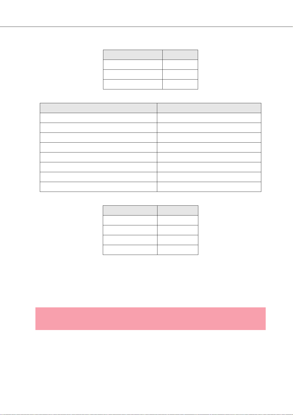
PowerH SERIES
Werkseinstellungen
Bedienelement Einstellung
Netzschalter Aus
CH A Level 0dB
CH B Level 0dB
Tabelle 2.1: Werkseinstellungen Bedienelemente
Parameter Wert
Power-On-Delay 0.00 s
Breaker Current (abhängig vom Leitungsnetz) 16 A (230 V) / 30 A (120 V)
Amplifier Name Dynacord H2500 bzw. Dynacord H5000
LCD Contrast 50%
LCD Brightness High 90%
LCD Brightness Low 40%
LCD Time to Dim Autodim off
Temperature Unit °C
Tabelle 2.2: Werkseinstellungen LC-Display
Bedienelement Einstellung
ROUTING DUAL
MODE NORMAL
SENSITIVITY/GAIN 0dBu
GROUNDLIFT GROUNDED
Tabelle 2.3: Werkseinstellungen Rückseite
2.2 Betriebsspannung
Die Spannungsversorgung der Endstufe erfolgt über den Anschluss MAINS IN, der als Neutrik
PowerCon® ausgeführt ist.
ACHTUNG:
Der Powercon
Powercon
52 Bedienungsanleitung
® ist ein Steckverbinder und keine Steckvorrichtung. Das heißt, der
® darf weder unter Last noch unter Spannung ein- und ausgesteckt werden.
Page 53

PowerH SERIES
Trennen Sie die Endstufe während der Installation immer von der Netzversorgung. Schließen Sie die
Endstufe nur an eine geeignete Netzversorgung an, die den auf dem Typenschild angegebenen
Anforderungen entspricht.
Abbildung 2.3: H2500/H5000 Typenschild
Gerät Spannung Netzfrequenz Leistungsaufnahme
H2500 100-240 V 50-60 Hz 1000 W
H5000 100-240 V 50-60 Hz 1450 W
Tabelle 2.4: Technische Daten Netzteil
Netzbetrieb & Wärmeentwicklung in der Endstufe
Mit Hilfe der folgenden Tabellen können die Anforderungen für Stromversorgung und Zuleitungen
bestimmt werden. Die vom Stromnetz aufgenommene Leistung wird in Ausgangsleistung für die
Lautsprecher und in Wärme umgewandelt. Die Differenz aus aufgenommener Leistung und abgegebener
Leistung nennt man Verlustleistung (P
und muss durch geeignete Maßnahmen abgeleitet werden. Zur Berechnung der Wärmeverhältnisse im
Rack/Schrank bzw. zur Dimensionierung eventuell benötigter Abluftmaßnahmen kann die nachfolgende
Tabelle benutzt werden. Die Spalte P
Spalte BTU/hr zeigt die abgegebene Wärmemenge je Stunde.
H2500
Idle 230 0.7 70 - 70 239
Max. Output Power @ 8 Ω
Max. Output Power @ 4 Ω
1/3 Max. Output Power @ 4 Ω
1/8 Max. Output Power @ 4 Ω
1/8 Max. Output Power @ 4 Ω
1/8 Max. Output Power @ 4 Ω
Normal Mode (-10 dB) @ 4 Ω
Rated Output Power (0 dB) @ 4 Ω
Alert (Alarm) Mode (-3 dB) @ 4 Ω
Max. Output Power @ 2 Ω
1/8 Max. Output Power @ 2 Ω
1/8 Max. Output Power @ 2 Ω
3
3
3
3
4
4 5
3
3
3
3
3
4
). Die durch Verluste entstehende Wärme verbleibt u. U. im Rack
d
zeigt die Verlustleistung bei verschiedenen Betriebszuständen. Die
d
U
in V I
mains
230 15.3 2420 2 x 850 720 2457
230 25.7 4300 2 x 1450 1400 4777
230 14.7 2325 2 x 483 1358 4635
230 6.2 875 2 x 181 513 1749
230 6.7 1000 2 x 181 588 2005
253 7.1 1105 2 x 219 666 2274
230 5.6 775 2 x 145 485 1655
230 23.5 3900 2 x 1200 1500 5118
230 16.7 2665 2 x 600 1465 4999
230 39.6 6920 2 x 2000 2920 9963
230 9.1 1345 2 x 238 870 2969
230 9.1 1335 2 x 238 860 2934
mains
in A P
mains
in W P
out
in W
Pd in W
1
BTU/hr
2
Bedienungsanleitung 53
Page 54

PowerH SERIES
H5000
Idle 230 0.7 78 - 78 266
Max. Output Power @ 8 Ω
Max. Output Power @ 4 Ω
1/3 Max. Output Power @ 4 Ω
1/8 Max. Output Power @ 4 Ω
1/8 Max. Output Power @ 4 Ω
1/8 Max. Output Power @ 4 Ω
Normal Mode (-10 dB) @ 4 Ω
Rated Output Power (0 dB) @ 4 Ω
Alert (Alarm) Mode (-3 dB) @ 4 Ω
Max. Output Power @ 2 Ω
1/8 Max. Output Power @ 2 Ω
1/8 Max. Output Power @ 2 Ω
= Verlustleistung
1.P
d
2.1 BTU = 1055.06 J = 1055.06 Ws
3.Sinusaussteuerung (1 kHz)
4.Rosa Rauschen gemäß EN60065 / 7. Edition
5.10% Netzüberspannung
3
3
3
3
4
4 5
3
3
3
3
3
4
U
in V I
mains
230 24.5 4089 2 x 1500 1089 3716
230 40.9 7137 2 x 2500 2137 7292
230 18.1 2927 2 x 833 1260 4300
230 6.2 877 2 x 313 252 860
230 9.6 1450 2 x 313 806 2750
253 11.6 1944 2 x 378 1188 4053
230 9.2 1368 2 x 250 868 2962
230 37.5 6445 2 x 2100 2245 7660
230 22.7 3760 2 x 1050 1660 5664
230 44.3 8180 2 x 3500 1180 4026
230 15.3 2427 2 x 438 1552 5296
230 13.6 2105 2 x 438 1230 4197
mains
in A P
mains
in W P
out
in W
Pd in W
1
BTU/hr
2
Die Stromaufnahmen für andere Netze können mit folgenden Faktoren direkt proportional umgerechnet
werden: 100 V = 2.3, 120 V = 1.9, 220 V = 1.05, 240 V = 0.97.
2.3 Netzschalter
Der Netzschalter an der Frontseite trennt die Endstufe von
der Netzversorgung. Durch Drücken des Netzschalters wird
das Hochfahren der Endstufe gestartet. Eine SoftstartSchaltung vermeidet dabei Einschaltstromspitzen auf der
Netzleitung. Dadurch wird verhindert, dass der
Leitungsschutzschalter des Stromnetzes beim Einschalten
der Endstufe anspricht.
Die Lautsprecher werden über die Ausgangsrelais um ca. 2
Sekunden verzögert zugeschaltet. Hierdurch werden
etwaige Einschaltgeräusche effektiv unterdrückt, die
ansonsten in den Lautsprechern hörbar wären. Während
dieser Verzögerung leuchtet die MUTE-LED und die Lüfter
sind in Betrieb.
54 Bedienungsanleitung
Page 55

PowerH SERIES
2.4 Einbau
Vordere Befestigung der Endstufe
Die PowerH-Endstufe wurde für den Einbau in ein konventionelles 19-Zoll Rack entwickelt. Befestigen
Sie die Endstufe an der Vorderseite mit 4 Schrauben und Unterlegscheiben wie in Abbildung 2.4
dargestellt.
Abbildung 2.4: Vordere Befestigung der Endstufe bei Rackeinbau
Hintere Befestigung
Wird das Rack, in dem die Endstufe eingebaut ist, transportiert, muss die Rückseite der Endstufe im Rack
befestigt werden. Bei fehlender Befestigung kann sowohl die Endstufe als auch das Rack beschädigt
werden. Die für die Befestigung benötigten Winkel sind im Lieferumfang der Endstufe enthalten.
Befestigen Sie die Endstufe wie in Abbildung 2.5 gezeigt mit Hilfe der vier mitgelieferten Käfigmuttern und
Befestigungsschrauben.
Abbildung 2.5: Hintere Befestigung der Endstufe
Bedienungsanleitung 55
Page 56
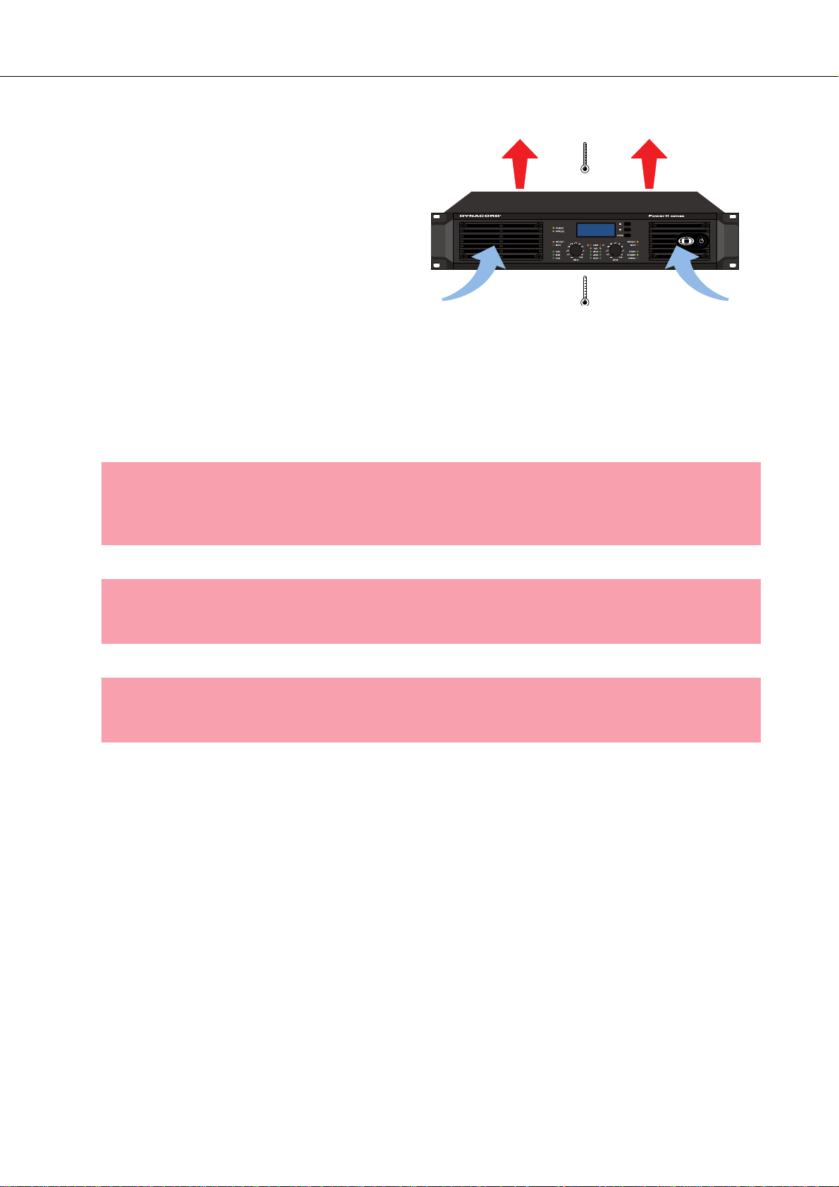
PowerH SERIES
2.5 Kühlung
Bei allen lüftergekühlen Endstufen von
Dynacord strömt die Luft von der Frontseite zur
Rückseite, da kühle Frischluft eher außerhalb
des Racks zur Verfügung steht als innerhalb.
Die Endstufe bleibt kühler und die entstehende
Abwärme kann gezielter abgeführt werden.
Generell ist die Endstufe so aufzustellen oder
zu montieren, dass die Luftzufuhr an der
Frontseite und die Entlüftung an der
Geräterückseite nicht behindert wird. Für den
Einbau in Gehäuse und Racks ist zu beachten,
dass eine ausreichende Belüftung der Endstufe
möglich ist. Zwischen der Endstufen-Rückseite und der Schrank/Rack-Innenseite ist ein freier Luftkanal
von mindestens 60 mm x 330 mm bis zur oberen Rack- oder Schrankentlüftung vorzusehen. Oberhalb des
Schrankes soll ein freier Raum von mindestens 100 mm für die Entlüftung vorgesehen werden. Da
während des Betriebs der Endstufe die Temperatur im Gehäuse- oder Schrank bis zu 40 °C ansteigen
kann, muss die maximal zulässige Umgebungstemperatur der übrigen im Gestellschrank befindlichen
Geräte beachtet werden.
Abbildung 2.6: H2500/H5000 Kühlung
ACHTUNG:
Die Lüftungsöffnungen der Endstufe dürfen nicht blockiert/verschlossen werden. Bei
fehlender Kühlung kann sich die Endstufe automatisch abschalten. Halten Sie alle
Lüftungsöffnungen frei von Staubablagerungen, die den Luftstrom behindern würden.
ACHTUNG:
Betreiben Sie die Endstufe nicht in der Nähe von Wärmequellen wie Heizlüftern, Öfen
oder anderen Geräten, die Hitze abstrahlen.
ACHTUNG:
Die maximale Umgebungstemperatur von +40°C soll für störungsfreien Betrieb nicht
überschritten werden.
Für Installationen mit einem zentralen Kühlluftsystem oder Klimageräten, wie es häufig bei
Festinstallationen in speziellen Geräteräumen verwendet wird, kann es nötig sein die maximale WärmeEmission zu berechnen. Beachten Sie hierzu die Angaben auf Seite 53.
2.6 Groundlift
Mit dem Groundlift-Schalter können Sie Brummschleifen verhindern. Wenn die Endstufe zusammen mit
anderen Geräten in einem Rack betrieben wird, sollte der Schalter in Stellung GROUNDED stehen. Wird
die Endstufe mit Geräten mit unterschiedlichem Erdungspotential betrieben, sollte der Schalter in Stellung
UNGROUNDED stehen.
56 Bedienungsanleitung
Page 57

PowerH SERIES
2.7 Anzeige der Betriebsart
An der Frontseite der Endstufe zeigen zwei LEDs die momentan gewählte Betriebsart der Endstufe an. Die
PARALLEL-LED leuchtet gelb, wenn die Stellung PARALLEL des Schalters ROUTING gewählt ist. Bei
Schalterstellung DUAL leuchtet die PARALLEL-LED nicht. Die BRIDGED-LED leuchtet gelb, wenn die
Stellung BRIDGED des Schalters MODE gewählt ist. Bei Schalterstellung NORMAL leuchtet die
BRIDGED-LED nicht.
2.8 Wahl der Betriebsart
ROUTING
Der Schalter ROUTING an der Rückseite der Endstufe bestimmt die Schaltung der Audioeingänge.
DUAL
In der Betriebsart DUAL arbeiten beide Kanäle der Endstufe unabhängig voneinander. Diese Betriebsart
wird bei allen 2-kanaligen Anwendungen wie Stereobetrieb oder Bi-Amp (Aktivbetrieb) verwendet. Über
die Eingangspegel-Regler an der Frontseite der Endstufe bzw. über ein optionales Remote-Control-Modul
und IRIS-Net™ lässt sich die Verstärkung der Kanäle getrennt justieren.
Abbildung 2.7: Einspeisung an beiden Eingängen bei Betriebsart DUAL
PARALLEL
In der Betriebsart PARALLEL sind die Eingänge der Kanäle A und B direkt elektrisch verbunden (gelinkt).
Das Eingangssignal ist über einen Eingang (XLR oder Phoenix) des Kanals A zuzuführen. Da nur die
Eingänge der beiden Kanäle miteinander verbunden sind, lässt sich weiterhin über die EingangspegelRegler oder IRIS-Net™ die Verstärkung der beiden Endstufenkanäle getrennt einstellen. Die Betriebsart
PARALLEL empfiehlt sich dann, wenn in größeren Anlagen mehrere Endstufenkanäle mit dem gleichen
Signal angesteuert werden sollen, z. B. beim Antrieb von größeren Bassarrays.
Abbildung 2.8: Einspeisung an Eingang A bei Betriebsart PARALLEL
Bedienungsanleitung 57
Page 58

PowerH SERIES
ACHTUNG:
In der Betriebsart PARALLEL kann nur am Eingangskanal A ein Signal eingespeist werden.
MODE
Der Schalter MODE an der Rückseite der Endstufe bestimmt die Betriebsart der Endstufenblöcke und
damit wie ein oder mehrere Lautsprecher angeschlossen werden müssen.
NORMAL
Im Zweikanalbetrieb (NORMAL) arbeiten beide Endstufenblöcke als unabhängige Endstufenkanäle. Die
Verstärkung jedes Kanals kann separat geregelt werden. Die Schaltung der Audio-Eingänge der Endstufe
ist nur von der Stellung des Schalters ROUTING abhängig.
BRIDGED
Im Brückenbetrieb (BRIDGED) arbeitet die Endstufe als einkanalige Mono-Endstufe. In Schalterstellung
DUAL, also getrennten Eingangskanälen, ist das Eingangssignal über einen Eingang (XLR oder Phoenix)
des Kanals A zuzuführen, die Eingänge des Kanals B sind inaktiv. In Schalterstellung PARALLEL ist das
Eingangssignal entweder über einen Eingang des Kanals A oder einen Eingang des Kanals B
zuzuführen. In der Betriebart BRIDGED wird die Endstufe im Kanal A ganz normal angesteuert. Zusätzlich
wird das Signal intern invertiert und auf die Endstufe im Kanal B gelegt. Die Endstufen A und B arbeiten
dann im Gegentakt mit verdoppelter Ausgangsspannung.
Abbildung 2.9: Betriebsart BRIDGED
ACHTUNG:
In der Betriebsart BRIDGED darf die angeschlossene Last 4 Ω nicht unterschreiten. Es
können sehr hohe Spannungen am Ausgang produziert werden. Die angeschlossenen
Lautsprecher müssen für derart hohe Spannungen ausgelegt sein. Beachten Sie unbedingt die Leistungsangaben im Datenblatt des jeweiligen Lautsprechers und vergleichen
Sie diese mit der entsprechenden Ausgangsleistung der Endstufe.
SENSITIVITY/GAIN
Endstufen der PowerH SERIES können entweder mit einer Eingangsempfindlichkeit (Input
Sensitivity) von 0dBu oder mit einer für alle Modelle definierten Verstärkung von 35dB oder 32dB
(Constant Gain) betrieben werden. Die über den Sensitivity/Gain-Schalter an der Rückseite der Endstufe
58 Bedienungsanleitung
Page 59

PowerH SERIES
gewählte Einstellung wird durch grünes Aufleuchten der entsprechend beschrifteten LED an der
Frontblende angezeigt.
HINWEIS:
Bei Verwendung eines Remote-Control-Moduls ist der Sensitivity/Gain-Schalter an der
Endstufe ohne Funktion. Es wird automatisch die Einstellung 35dB festgelegt.
Eine Eingangsempfindlichkeit von 0dBu bedeutet, dass bei einem Eingangssignal von 0 dBu (0.775 V
rms
am Endstufenausgang die Nennleistung (Rated Output Power) abgegeben wird. Diese Einstellung
empfiehlt sich bei Signalquellen, die eine nominale Spannung von 0 dBu liefern.
Alternativ kann die Endstufe auch mit einer festen Verstärkung (Constant Gain) von 35 dB oder 32 dB
betrieben werden. Wenn man in einem Setup alle Endstufen - auch unterschiedlicher Leistungsklassen mit Constant Gain Einstellung betreibt, ist die Justierung von Signalprozessoren besonders einfach. In
diesem Fall kann unabhängig von der tatsächlichen Maximalleistung der einzelnen Endstufen jede
Endstufe beim Erstellen der Gainstruktur mit 35 dB (bzw. 32 dB) berücksichtigt werden. Etwaige Limiter
werden dann auf die maximale Belastbarkeit der Lautsprecherkomponenten justiert.
Audio Verkabelung
Eingang (XLR / Phoenix)
Die Eingänge IN A und IN B sind elektronisch symmetrisch ausgelegt. Die Eingangsempfindlichkeit kann
über den SENSITIVITY-Schalter eingestellt werden. Der Anschluss kann entweder über die XLR-
Eingangsbuchsen oder die hierzu parallelgeschalteten Schraubsteckverbindungen (Phoenix) erfolgen. Die
hierfür benötigten Phoenix-Verbinder sind im Lieferumfang der Endstufe enthalten. Die XLREingangsbuchsen sind nach IEC Norm 268 beschaltet.
2, HOT
COLD, -
)
HOT, +
3, COLD
1, SHIELD
SHIELD
Abbildung 2.10: Symmetrische Beschaltung des Eingangs
Falls möglich, sollte stets ein symmetrisches Audiosignal am Eingang der Endstufe verwendet werden.
Falls das/die Anschlusskabel sehr kurz sind und keine Störsignale in der Umgebung der Endstufe zu
erwarten sind, kann auch ein unsymmetrisches Signal angeschlossen werden. In diesem Fall ist es
zwingend erforderlich eine Brücke im Eingangsstecker zwischen Schirm und dem invertierenden Eingang
zu schalten, da ansonsten ein Pegelverlust von 6 dB auftreten kann. Vergleichen Sie dazu bitte
Abbildung 2.11. Aus Gründen der Störfestigkeit gegenüber externen Störquellen wie z. B. Dimmer,
Bedienungsanleitung 59
Page 60

PowerH SERIES
Netzzuführungen, HF-Steuerleitungen usw. ist jedoch eine symmetrische Verkabelung immer zu
bevorzugen.
3, COLD
2, HOT
JUMPER
FROM COLD
TO SHIELD
JUMPER FROM COLD TO SHIELD
HOT, +
SHIELD
Abbildung 2.11: Unsymmetrische Beschaltung des Eingangs
Zusätzlich zu den Eingängen steht für jeden Kanal jeweils eine parallel geschaltete XLR-Buchse (OUT A
bzw. OUT B) zur Verfügung. Über diese kann das Audiosignal komfortabel zu anderen Geräten
weitergeführt werden (Daisy-Chain).
1, SHIELD
3, COLD
2, HOT
Abbildung 2.12: Symmetrische Beschaltung des Ausgang (Daisy-Chain)
Ausgang (Speakon / Anschlussklemmen) im Normal Mode
Der Anschluss von Lautsprechern an die PowerH-Endstufe unterscheidet sich je nach gewählter
Betriebsart der Endstufenblöcke, also der Stellung des Schalters MODE an der Rückseite der Endstufe. In
der Betriebsart NORMAL können Lautsprecher auf zwei verschiedene Weisen, in typischer Lautsprecherbzw. in Bi-Amp-Verkabelung, angeschlossen werden.
Typische Lautsprecherverkabelung
Die erste Möglichkeit ist die Verwendung beider Speakon-Buchsen, wobei in jeder der Buchsen der
Lautsprecher jeweils an den Anschlüssen 1+ und 1- angeschlossen wird, siehe Abbildung 2.13.
Abbildung 2.13: Lautsprecheranschluss in Betriebsart NORMAL an Speakon A und B
60 Bedienungsanleitung
Page 61
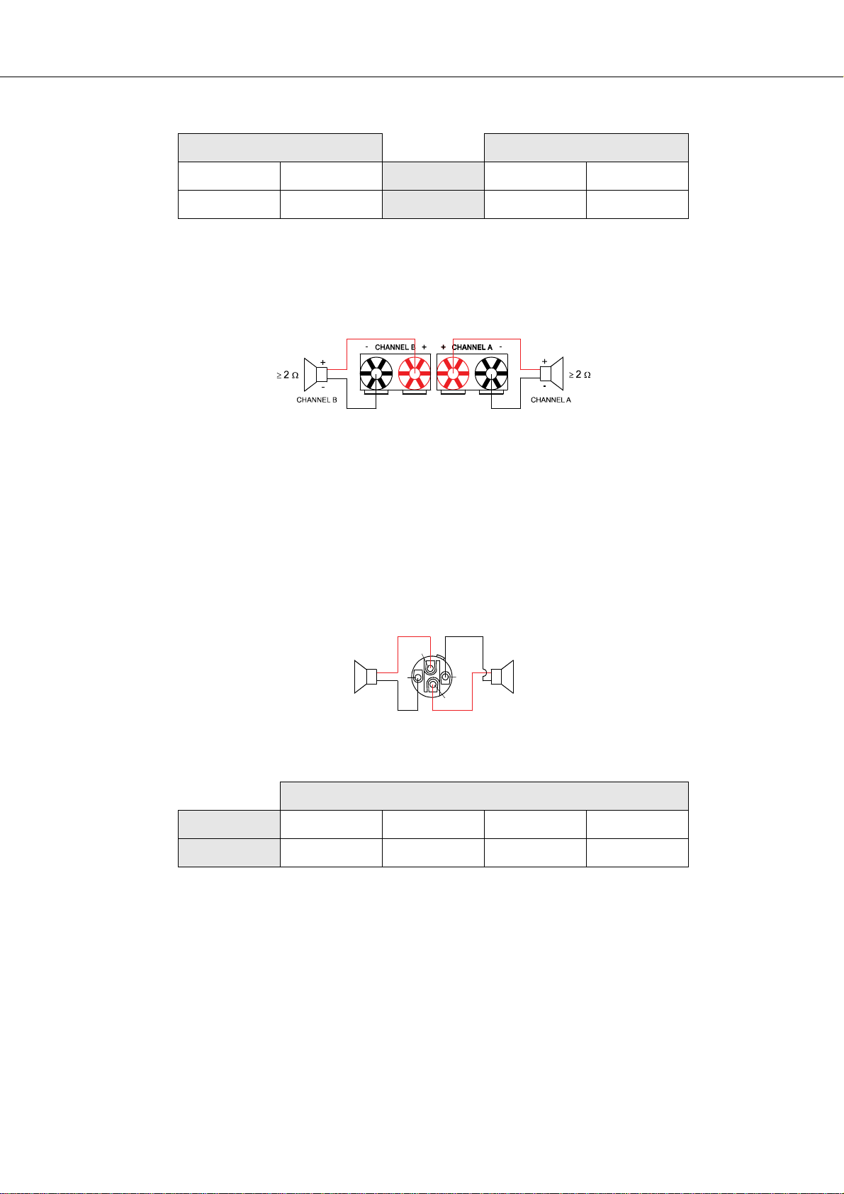
PowerH SERIES
Speakon CH B Speakon CH A
1+ 1-
B+ B-
Anschluss 1+ 1-
Belegung A+ A-
Tabelle 2.5: Lautsprecheranschluss in Betriebsart NORMAL an Speakon A und B
Neben den Speakon-Buchsen stehen für den Anschluss von Lautsprechern auch Anschlussklemmen zur
Verfügung. In der Betriebsart NORMAL werden die Lautsprecher entsprechend folgender Abbildung
angeschlossen.
Abbildung 2.14: Lautsprecheranschluss in Betriebsart NORMAL an Anschlussklemmen
Bi-Amp Verkabelung
Die zweite Möglichkeit zum Anschluss von Lautsprechern an die Endstufe in der Betriebsart NORMAL ist
die alleinige Verwendung der Speakon-Buchse CH A. In dieser kann wie zuvor beschrieben der eine
Lautsprecher an den Anschlüssen 1+ und 1- angeschlossen werden. Der andere Lautsprecher ist
entsprechend Abbildung 2.14 an den Anschlüssen 2+ und 2- anzuschließen. Die Anschlüsse 2+ und 2sind nur im Speakon CH A belegt. Dieses Vorgehen ermöglicht eine einfache Verkabelung von
Lautsprechern, die im aktiv 2-Weg-Betrieb verwendet werden (Bi-Amp).
1+
+
≥ 2 Ω≥ 2 Ω
1-
-
2+
CH ACHANNEL A CHANNEL B
+
2-
-
Abbildung 2.15: Bi-Amp-Lautsprecheranschluss in Betriebsart NORMAL nur an Speakon A
Speakon CH A
Anschluss1+1-2+2-
BelegungA+A-B+B-
Tabelle 2.6: Bi-Amp-Lautsprecheranschluss in Betriebsart NORMAL nur an Speakon A
Bedienungsanleitung 61
Page 62

PowerH SERIES
Ausgang (Speakon / Anschlussklemmen) im Bridged Mode
Läuft die Endstufe durch Wahl der Schalterstellung BRIDGED des Schalters MODE an der Rückseite im
Brückenbetrieb, ist der Lautsprecher an der Speakon-Buchse CH A an den Anschlüssen 1+ und 2+ zu
betreiben, siehe Abbildung 2.15.
Abbildung 2.16: Lautsprecheranschluss in Betriebsart BRIDGED an Speakon A
Speakon CH A
Anschluss 1+ 2+
Belegung Bridged+ Bridged-
Tabelle 2.7: Lautsprecheranschluss in Betriebsart BRIDGED an Speakon A
An den Anschlussklemmen wird in der Betriebsart BRIDGED der Lautsprecher zwischen den roten
Klemmen von CHANNEL A und CHANNEL B angeschlossen. Die korrekte Anschlussweise für diese
Betriebsart ist zusätzlich auf der Endstufe selbst abgebildet.
Abbildung 2.17: Lautsprecheranschluss in Betriebsart BRIDGED an Anschlussklemmen
ACHTUNG:
Die Verwendung von Lamellen-/Büschelsteckern zum Anschluss von Lautsprechern ist
aufgrund der auftretenden Stromstärken nicht zulässig.
62 Bedienungsanleitung
Page 63

PowerH SERIES
3 Betrieb
3.1 Volume Control
In den Betriebsarten DUAL und PARALLEL regeln die Levelsteller CH A bzw. CH B an der Frontseite der
Endstufe die Verstärkung des jeweiligen Kanals. Drehung nach rechts erhöht die Lautstärke, Drehung
nach links verringert die Lautstärke. In der Betriebsart BRIDGED regelt nur der Drehknopf CH A die
Lautstärke der Endstufe. Änderungen der Einstellung des Drehknopfs CH B werden ignoriert.
Ist in die Endstufe ein Remote-Control-Modul eingebaut, können die Drehknöpfe CH A bzw. CH B
deaktiviert sein. Die Verstärkung der Endstufe kann in diesem Fall nur über IRIS-Net™ geregelt werden.
Auf die Deaktivierung der Drehknöpfe wird im LC-Display durch die Anzeige Level Controls Off !
hingewiesen.
Abbildung 3.1: Levelsteller CH A und CH B
3.2 Graphisches LC-Display
Über das graphische LC-Display können detaillierte Informationen über den Zustand der Endstufe
abgerufen werden. Darüber hinaus können diverse Einstellungen an der Endstufe und, falls vorhanden, an
einem Remote-Control-Modul vorgenommen werden.
Abbildung 3.2: LC-Display mit Bedienelementen
1
Tasten Up und Down : Durch Betätigen der Tasten navigieren Sie durch das Menü.
Tas te ENTER: Auswahl des angezeigten Menüeintrags im LC-Display.
2
Bedienungsanleitung 63
Page 64

PowerH SERIES
Menüführung Endstufe
Nach dem Einschalten der Endstufe wird der Startbildschirm mit der Typenbezeichnung der Endstufe
angezeigt. Nach einigen Sekunden wird die Statusanzeige der Endstufe dargestellt. In der obersten Zeile
wird immer die Bezeichnung der Endstufe angezeigt. Die zweite und dritte Zeile liefert einen Überblick
über den aktuellen Zustand der Endstufe. Blinkende Werte in Zeile 2 weisen auf das Erreichen des jeweils
zulässigen Betriebsbereiches hin. Ist in die Endstufe z.B. ein RCM-26 eingebaut, werden zusätzliche
Informationen dargestellt.
Abbildung 3.3: Statusanzeige der Endstufe ohne bzw. mit eingebautem RCM-26 (Beispiel)
Durch Betätigung der Up/Down-Tasten kann in der unteren Zeile der Statusanzeige geblättert werden. In
folgender Tabelle sind die dabei nacheinander angezeigten Informationen zusammengefasst.
Eingestellte CAN-Adresse und CAN-Baudrate
(nur bei eingebautem RCM-26)
Bezeichnung des aktuell verwendeten Presets
(nur bei eingebautem RCM-26)
In Betrieb befindlicher Audioeingang der Endstufe
(nur bei eingebautem RCM-26)
Zustand der Eingangspegel-Regler an der Frontblende
(nur bei eingebautem RCM-26)
Anzeige der Schaltung der Audio-Eingänge, der Betrieb-
sart der Endstufenblöcke und der Parameter der
Schutzschaltung Mains Circuit Breaker Protection falls
dessen Werkseinstellung geändert wurde
(RCM-26 nicht eingebaut)
Anzeige der Einschaltverzögerung der Endstufe
Aktueller Parameter für die Schutzschaltung Mains Cir-
cuit Breaker Protection
Betätigung der ENTER-Taste wechselt in das Konfigura-
tionsmenü CONFIG.
Tabelle 3.1: Übersicht Statusanzeige
64 Bedienungsanleitung
Page 65

PowerH SERIES
Folgende Abbildung stellt die Struktur des Menüs CONFIG (und der zugehörigen Untermenüs) ausgehend
von der Statusanzeige dar. Mit * markierte Menüeinträge sind nur dann verfügbar, wenn kein Remote
Control Modul eingebaut ist.
Status display
EVENT LOG
Counter POWER UP
Counter AMP ON
Counter PROTECT
Counter AMP MUTE
Counter MAINS FAIL
Uptime
Show Event History
Power-On-Delay
Breaker Current
Show Event Log
Menu Display
Menu Service
Amplifier Name*
EXIT
DISPLAY SETUP
LCD Contrast
LCD Brightness
LCD Time to Dim
Temperature Unit
BACK
SERVICE
Restore Amplifier’s
Factory Settings
Reset Event Log
BACK
Lifetime
Last Log
Module Signature
Firmware Version
BACK
Abbildung 3.4: Menüstruktur der Endstufe
Bedienungsanleitung 65
Page 66

PowerH SERIES
Menüstruktur CONFIG
Das Konfigurationsmenü CONFIG erreicht man durch Drücken der ENTER-Taste bei Anzeige des Eintrags
>> CONFIG << im Statusdisplay. Nachfolgend sind die einzelnen Einträge des Konfigurationsmenüs
erläutert.
CONFIG.Power-On-Delay: Es wird die momentan eingestellte
Einschaltverzögerung der Endstufe angezeigt. Durch Drücken der
ENTER-Taste gelangt man in den Dialog Set Power-On-Delay.
Im Dialog Set Power-On-Delay kann durch Drücken der Up/
Down-Tasten die Verzögerung zwischen 0 Sekunden und 6.35
Sekunden eingestellt werden. Drücken der ENTER-Taste
übernimmt die gewählte Verzögerung und führt in das Menü
zurück.
CONFIG.Breaker Current: Es wird der momentan für die
Schutzschaltung Mains Circuit Breaker Protection eingestellte
Stromwert angezeigt. Für die korrekte Funktion dieser
Schutzschaltung muss der hier eingestellte Stromwert der
Absicherung der Endstufe angepasst werden. Bitte beachten Sie
hierzu die Hinweise auf Seite 76. Durch Drücken der ENTER-
Taste gelangt man in den Dialog Set Breaker Current.
Im Dialog Set Breaker Current kann durch Drücken der Up/
Down-Tasten der gewünschte Stromwert eingestellt werden. Die
zulässigen Wertebereiche hängen von der Spannungsversorgung
der Endstufe ab. In der Betriebsart 120 V können Ströme
zwischen 6 A und 40 A eingestellt werden. In der Betriebsart 220240 V können Ströme zwischen 6 A und 30 A eingestellt werden.
Durch Auswahl der jeweils unterhalb von 6 A zur Verfügung
stehenden Option Factory 30 A bzw. Factory 16 A werden
in Abhängigkeit der verwendeten Versorgungsspannung die
jeweiligen Werkseinstellungen gewählt. Drücken der ENTER-
Taste übernimmt den gewählten Stromwert und führt in das Menü
zurück.
HINWEIS:
Es wird empfohlen die Endstufe stets an einem separat abgesicherten Stromkreis zu betreiben.
CONFIG.Show Event Log: Der Menüeintrag Show Event Log
führt in das Untermenü EVENT LOG.
Die einzelnen Einträge des Menüs EVENT LOG sind im Abschnitt
Menüstruktur CONFIG.EVENT LOG (siehe Seite 68) erläutert.
66 Bedienungsanleitung
Page 67

CONFIG.Menu Display: Der Menüeintrag Menu Display führt in
das Untermenü DISPLAY SETUP.
Die einzelnen Einträge des Menüs DISPLAY SETUP sind im
Abschnitt Menüstruktur CONFIG.DISPLAY SETUP (siehe Seite 69)
erläutert.
CONFIG.Menu Service: Der Menüeintrag Menu Service führt in
das Untermenü SERVICE.
Die einzelnen Einträge des Menüs SERVICE sind im Abschnitt
Menüstruktur CONFIG.SERVICE (siehe Seite 70) erläutert.
CONFIG.Amplifier Name: Zeigt die Bezeichnung der Endstufe
an. Dieser Menüpunkt ist nur vorhanden, wenn in die Endstufe
kein RCM-26 eingebaut ist. Falls ein Remote-Control-Modul
vorhanden ist, wird die Bezeichnung der Endstufe über IRIS-Net™
eingegeben. Durch Drücken der ENTER-Taste gelangt man in den
Dialog Set Amplifier Name.
PowerH SERIES
Im Dialog Set Amplifier Name kann die Bezeichnung der
Endstufe geändert werden. Die Bezeichnung kann maximal 20
Zeichen lang sein, es stehen die Buchstaben a-z, A-Z, 0-9 und
Sonderzeichen zur Verfügung.
Durch Drücken der Up/Down-Tasten wird die mit dem Cursor
gewählte Stelle der Bezeichnung bearbeitet. Drücken der ENTER-
Taste übernimmt das gewählte Zeichen und bewegt den Cursor
zur nächsten Stelle. Drücken der ENTER-Taste nach Bearbeitung
der letzten Stelle übernimmt die gewünschte
Endstufenbezeichnung und führt in das Menü zurück.
Folgende Sonderzeichen besitzen während der Eingabe besondere Bedeutung:
Zeichen Bedeutung
↵ Übernimmt die eingegebene Bezeichnung und kehrt in das Menü zurück.
A
I
Löscht das momentan gewählte Zeichen und bewegt den Cursor eine Stelle nach rechts.
Bewegt den Cursor eine Stelle nach links.
Tabelle 3.2: Sonderzeichen bei Eingabe der Endstufenbezeichnung
Bedienungsanleitung 67
Page 68

PowerH SERIES
Menüstruktur CONFIG.EVENT LOG
CONFIG.EVENT LOG.Counter POWER UP: Es wird die Anzahl
der Betätigungen des Netzschalters an der Frontseite angezeigt.
CONFIG.EVENT LOG.Counter AMP ON: Es wird die Anzahl der
Aktivierungen der Endstufe, sowohl aus dem Zustand Aus als auch
aus dem Zustand Standby, angezeigt.
CONFIG.EVENT LOG.Counter PROTECT: Es wird die Anzahl des
Ansprechens einer Schutzschaltung angezeigt.
CONFIG.EVENT LOG.Counter AMP MUTE: Es wird die Anzahl
von Stummschaltungen der Endstufe durch eine Schutzschaltung
angezeigt.
CONFIG.EVENT LOG.Counter MAINS FAIL: Es wird die Anzahl
der Auftretens einer Über- oder Unterspannung der
Spannungsversorgung der Endstufe angezeigt.
CONFIG.EVENT LOG.Uptime: Es wird die Laufzeit der Endstufe
(ohne Standby-Zeiten) seit dem letzten Rücksetzen des Event
Logs angezeigt.
CONFIG.EVENT LOG.Show Event History: Der Menüeintrag
Show Event History führt in die chronologische Liste von
Ereignissen, die in der Endstufe aufgetreten sind. Der erste
Eintrag der Liste ist das zuletzt eingetretene Ereignis. Durch
Drücken der ENTER-Taste gelangt man zu den einzelnen
Einträgen.
Für jeden Eintrag in der Liste wird der Zeitpunkt und die Ursache
des Auftretens angezeigt. Für jedes Ereignis wird der Zustand des
Verstärkers (Amp) und der beiden Ausgangskanäle (Ch A bzw.
Ch B) dargestellt. In den Einträgen der Liste kann durch Drücken
der Up/Down-Tasten geblättert werden. Drücken der ENTER-
Taste führt in das Menü zurück.
68 Bedienungsanleitung
Page 69

CONFIG.EVENT LOG.Reset Event Log: Das Event Log der
Endstufe kann komplett zurückgesetzt werden. Durch das
Rücksetzen werden alle Zähler auf Null gesetzt und die
Ereignisliste wird gelöscht. Durch Drücken der ENTER-Taste
gelangt man zu einer Sicherheitsabfrage. In der Sicherheitsabfrage
kann durch Drücken der Up/Down-Tasten zwischen YES und NO
gewählt werden. Drücken der ENTER-Taste setzt bei Wahl von
YES das Event Log zurück, bei Wahl von NO wird ohne Änderung
des Event Logs in das Menü zurückgekehrt.
Menüstruktur CONFIG.DISPLAY SETUP
CONFIG.DISPLAY SETUP.LCD Contrast: Es wird der momentan
eingestellte Kontrast des LC-Displays angezeigt. Durch Drücken
der ENTER-Taste gelangt man in den Dialog
Set LCD Contrast.
PowerH SERIES
Im Dialog Set LCD Contrast kann durch Drücken der Up/
Down-Tasten der Kontrast zwischen 0 % und 100 % eingestellt
werden. Drücken der ENTER-Taste übernimmt den gewählten
Kontrastwert und führt in das Menü zurück.
CONFIG.DISPLAY SETUP.LCD Brightness: Es wird die
momentan eingestellte obere und untere Grenze der DisplayHelligkeit angezeigt.
Die obere Grenze stellt die Helligkeit des Displays dar, die
während des normalen Betriebs verwendet wird. Die untere
Grenze stellt die Helligkeit des Displays dar, auf die das Display,
falls gewünscht, nach einer bestimmten Zeitdauer zurückgeregelt
wird. Durch Drücken der ENTER-Taste gelangt man in den Dialog
Set Brightn. Hi-Lvl.
Im Dialog Set Brightn. Hi-Lvl kann durch Drücken der Up/
Down-Tasten die ungedimmte Display-Helligkeit zwischen 50 %
und 100 % eingestellt werden. Drücken der ENTER-Taste
übernimmt den gewählten Helligkeitswert und führt in den Dialog
Menü Set Brightn. Lo-Lvl weiter.
Im Dialog Set Brightn. Lo-Lvl kann durch Drücken der Up/
Down-Tasten die gedimmte Display-Helligkeit zwischen 0 % und
80 % eingestellt werden. Drücken der ENTER-Taste übernimmt
den gewählten Helligkeitswert und führt in das Menü zurück.
Bedienungsanleitung 69
Page 70

PowerH SERIES
CONFIG.DISPLAY SETUP.LCD Time to Dim: Es wird die
momentan eingestellte Beleuchtungsdauer des Displays
angezeigt.
Nach Ablauf dieser Zeitdauer wird die Displaybeleuchtung
zurückgedimmt. Durch Drücken der ENTER-Taste gelangt man in
den Dialog Set LCD Time to Dim.
Im Dialog Set Time to Dim kann durch Drücken der Up/DownTasten die Zeitdauer bis zum Dimmvorgang der
Displaybeleuchtung eingestellt werden. Einerseits kann die
Zeitdauer auf 4, 8, 16, 32 bzw. 64 Minuten eingestellt werden,
andererseits kann die Dimmfunktion des Displays über die
Einstellung Autodim off auch deaktiviert werden. In diesem Fall
wird die Displaybeleuchtung immer mit der ungedimmten DisplayHelligkeit (Brightn. Hi-Lvl) betrieben. Um die Lebensdauer
der Displaybeleuchtung zu erhöhen sollte die Dimmfunktion
aktiviert sein. Drücken der ENTER-Taste übernimmt die gewählte
Einstellung und führt in das Menü zurück.
CONFIG.DISPLAY SETUP.Temperature Unit: Es wird die
momentan gewählte Einheit für Temperatur-Angaben im Display
angezeigt. Durch Drücken der ENTER-Taste gelangt man in den
Dialog Set Temperature Unit.
Im Dialog Set Temperature Unit kann durch Drücken der Up/
Down-Tasten zwischen den Einheiten °C (Grad Celsius) und °F
(Grad Fahrenheit) gewählt werden. Drücken der ENTER-Taste
übernimmt die gewünschte Einheit und führt in das Menü zurück.
Menüstruktur CONFIG.SERVICE
CONFIG.SERVICE.Restore Amplifier’s Factory Settings: Die
Endstufe kann auf Werkseinstellungen zurückgesetzt werden.
Durch Drücken der ENTER-Taste gelangt man zu einer
Sicherheitsabfrage. In der Sicherheitsabfrage kann durch Drücken
der Up/Down-Tasten zwischen YES und NO gewählt werden.
Drücken der ENTER-Taste setzt bei Wahl von YES die Endstufe auf
Werkseinstellungen zurück, bei Wahl von NO wird ohne Änderung
der Endstufenparameter in das Menü zurückgekehrt.
70 Bedienungsanleitung
Page 71
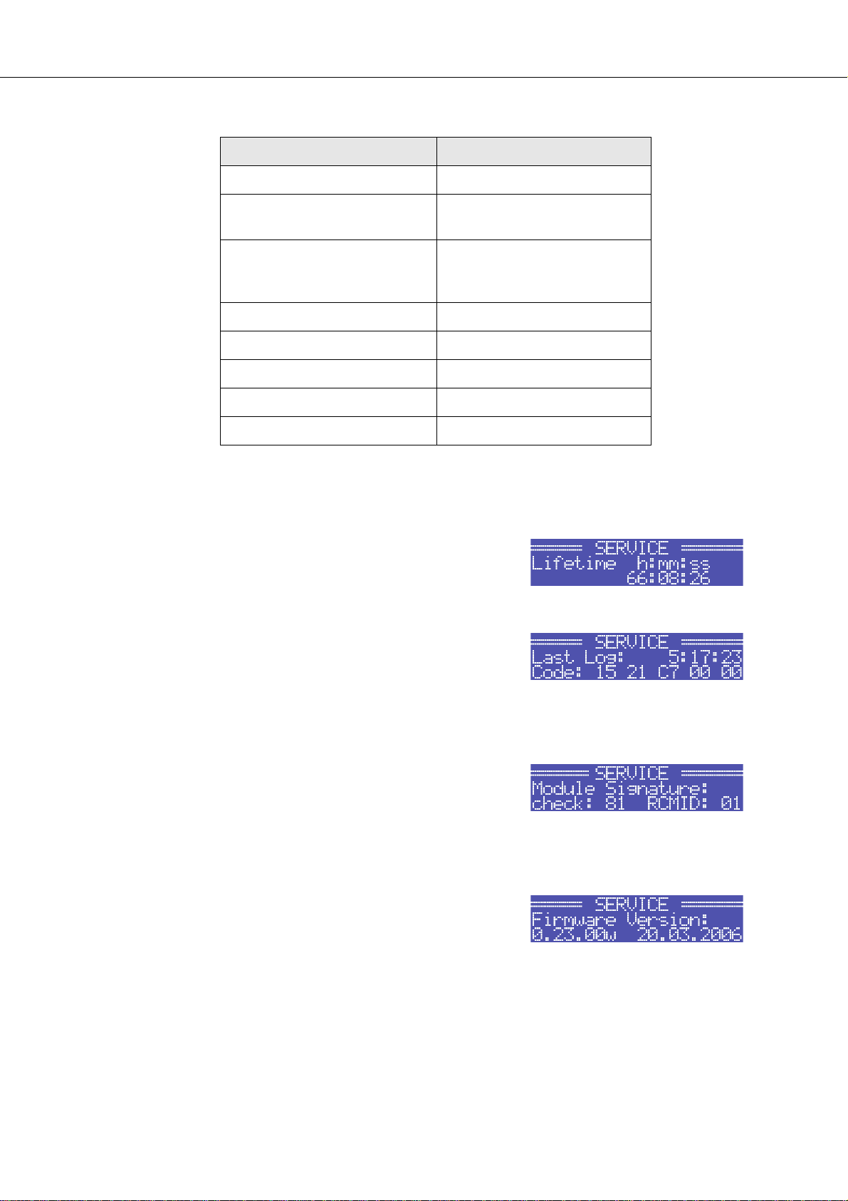
PowerH SERIES
Die durch den Rücksetzvorgang betroffenen Parameter sind in folgender Tabelle zusammengefasst:
Parameter Wert
Power-On-Delay 0.00 s
Breaker Current (abhängig von
Versorgungsspannung)
Amplifier Name Dynacord H2500
LCD Contrast 50%
LCD Brightness High 90%
LCD Brightness Low 40%
LCD Time to Dim Autodim off
Temperature Unit °C
Tabelle 3.3: Werkseinstellungen LC-Display
CONFIG.SERVICE.Lifetime: Zeigt die gesamte Laufzeit der
Endstufe (ohne Standby-Zeit) an.
16 A (230 V) / 30 A (120 V)
Dynacord H5000
bzw.
CONFIG.SERVICE.Last Log: Es wird Zeitpunkt und Art des
letzten Eintrags im Event Log angezeigt. Der angezeigte Code
kann im Fehlerfall Ihrem Dynacord Service-Partner nähere
Hinweise auf die genaue Fehlerursache geben.
CONFIG.SERVICE.Module Signature: Falls ein Remote-Control
Modul eingebaut ist, können die angezeigten Informationen im
Fehlerfall Ihrem Dynacord Service-Partner nähere Hinweise auf
die genaue Fehlerursache geben.
CONFIG.SERVICE.Firmware Version: Zeigt die Version und das
Datum der Firmware der Endstufe an.
Bedienungsanleitung 71
Page 72

PowerH SERIES
Menüstruktur MODULE CONFIG
Alle Einstellmöglichkeiten am Remote-Control-Modul RCM-26 über das LC-Display der Endstufe sind in
einem eigenen Menü MODULE CONFIG zusammengefasst. Dieses Menü ist während des Betriebs der
Endstufe nicht zugänglich. Der Zugang zu diesem Menü ist nur von der ausgeschalteten Endstufe aus
möglich. Folgende Schritte öffnen des Menü MODULE CONFIG:
1. Falls die Endstufe eingeschaltet oder im Standby-Modus ist, schalten Sie die Endstufe über den
Netzschalter an der Frontblende aus.
2. Betätigen Sie gleichzeitig die beiden Tasten Up und ENTER und halten Sie diese gedrückt.
3. Schalten sie die Endstufe über den Netzschalter an der Frontblende ein.
Die Endstufe schaltet in den Standby-Modus und zeigt das Menü
MODULE CONFIG an.
Abbildung 3.5 stellt die Struktur des Menüs MODULE CONFIG einer Endstufe der PowerH SERIES
mit Remote-Control-Modul RCM-26 dar.
EXIT
Preset
CAN-Baudrate
Audio-Input
Power
Abbildung 3.5: Menüstruktur Module Setup (RCM-26)
Nachfolgend sind die einzelnen Einträge des Menüs MODULE CONFIG erläutert.
72 Bedienungsanleitung
Page 73

PowerH SERIES
MODULE CONFIG.Preset: Es wird die Bezeichnung des
momentan aktiven Presets angezeigt. Durch Drücken der ENTER-
Taste gelangt man in den Dialog Load Preset.
Im Dialog Load Preset kann durch Drücken der Up/DownTasten zwischen den verschiedenen Presets gewählt werden.
Drücken der ENTER-Taste führt zu einer Sicherheitsabfrage, ob
das Preset wirklich geladen werden soll. In diesem Dialog kann
durch Drücken der Up/Down-Tasten zwischen YES und NO
gewählt werden. Drücken der ENTER-Taste bei Wahl von YES lädt
das gewählte Preset und kehrt in das Menü zurück. Bei Wahl von
NO wird das gewählte Preset nicht geladen, das aktive Preset der
Endstufe bleibt unverändert und es wird in das Menü
zurückgekehrt.
ACHTUNG:
Das selektierte Preset muss für die Verwendung mit den angeschlossenen Lautprecherkomponenten geeignet sein. Ein falsch justiertes Preset kann zur Zerstörung der Lautsprecher führen.
MODULE CONFIG.CAN-Baudrate: Es wird die momentan
eingestellte CAN-Baudrate des RCM-26 angezeigt. Durch
Drücken der ENTER-Taste gelangt man in den Dialog Set CAN-
Baudrate.
Im Dialog Set CAN-Baudrate kann durch Drücken der Up/
Down-Tasten zwischen den CAN-Baudraten 10kBaud, 20kBaud,
62.5kBaud, 125kBaud, 250kBaud und 500kBaud gewählt
werden. Drücken der ENTER-Taste übernimmt die gewünschte
Baudrate und führt in das Menü zurück.
ACHTUNG:
Alle Geräte an einem CAN-BUS müssen immer dieselbe Baudrate verwenden.
MODULE CONFIG.Audio-Input: Es wird der momentan
verwendete Audioeingang angezeigt. Durch Drücken der ENTER-
Taste gelangt man in den Dialog Select Audio-Input.
Im Dialog Select Audio-Input kann durch Drücken der Up/
Down-Tasten zwischen den Eingängen Analog und AES/EBU
gewählt werden. Drücken der ENTER-Taste übernimmt den
gewünschte Eingang und führt in das Menü zurück.
Bedienungsanleitung 73
Page 74

PowerH SERIES
MODULE CONFIG.Power: Es wird der Zustand der Endstufe
nach Betätigung des Netzschalters angezeigt.
Falls die Endstufe über IRIS-Net™ in den Standby-Modus
geschaltet und über den Netzschalter ausgeschaltet wurde, wird
der Standby-Zustand beim nächsten Einschalten der Endstufe
über den Netzschalter angenommen. Über diesen Menüpunkt
kann eine Endstufe im Standby-Modus auch ohne IRIS-Net™
wieder hochgefahren werden. Durch Drücken der ENTER-Taste
gelangt man in den Dialog Set Power.
In diesem Dialog kann durch Drücken der Up/Down-Tasten
zwischen den Zuständen On und Standby gewählt werden.
Drücken der ENTER-Taste übernimmt den gewünschten Zustand
und führt in das Menü zurück.
3.3 Anzeigen
PROTECT
Wenn die PROTECT-LED gelb aufleuchtet, hat eine der internen Schutzschaltungen der Endstufe
angesprochen. Das Aufleuchten der PROTECT-LED bedeutet jedoch nicht unweigerlich die Abschaltung
des Signalweges. Das gestaffelte Schutzkonzept der PowerH SERIES bewirkt, dass mehrere
Schutzschaltungen nacheinander greifen. Hierdurch wird die Endstufe den sicheren und stabilen
Arbeitsbereich im Normalfall nie verlassen. Sollte dennoch die Abschaltung notwendig werden, um
bleibende Schäden von der Endstufe und den angeschlossenen Lautsprechern fernzuhalten, wird dies
über gleichzeitiges Aufleuchten der PROTECT- und MUTE-LED angezeigt.
MUTE
Die MUTE-LED leuchtet rot auf, wenn die Endstufe stumm geschaltet ist. Dies tritt z.B. während der
Lautsprecher-Einschaltverzögerung, beim Umschalten der Eingangsempfindlichkeit oder bei der
manuellen Stummschaltung über IRIS-Net™ auf.
-30dB…LIMIT
Die Pegelanzeige an der Frontseite der Endstufe erfolgt getrennt für die beiden Kanäle mit den jeweiligen
LEDs -30dB, -20dB, -10dB unter Vollaussteuerung und 0dB sobald die Aussteuerungsgrenze erreicht ist.
Die 0 dB-Anzeige wird endstufenintern aus einem Vergleich von Ausgangsspannung zu
Eingangsspannung gewonnen und zeigt somit präzise die Aussteuerungsgrenze an, noch bevor eine
hörbare Begrenzung auftritt. Wird das Eingangssignal über die 0 dB-Grenze erhöht setzt der Clip-Limiter
ein, der den weiteren Anstieg des Klirrfaktors zuverlässig auf 1 % begrenzt. Die dabei rot aufleuchtende
LIMIT-LED verfügt über eine dynamische Helligkeitssteuerung, wodurch leicht abzulesen ist, wie weit sich
das Signal in der Begrenzung befindet.
74 Bedienungsanleitung
Page 75

PowerH SERIES
POWER
Die POWER-LED leuchtet grün auf, wenn die Endstufe eingeschaltet ist. Falls die POWER-LED trotz
eingeschaltetem Gerät nicht leuchtet, ist das Gerät entweder nicht mit dem Stromnetz verbunden, die
Primärsicherung defekt, oder die Endstufe befindet sich im Standby-Modus (STANDBY-LED leuchtet gelb).
Die POWER-LED blinkt, wenn die Spannung am Eingang MAINS IN entweder zu hoch (Überspannung)
oder zu niedrig (Unterspannung) ist. In diesem Fall lässt sich die Endstufe nicht einschalten.
STANDBY
Die STANDBY-LED leuchtet gelb, wenn sich die Endstufe im Standby-Modus befindet. Im Standby-Modus
ist die Leistungsaufnahme des Gerätes auf ein Minimum reduziert. Die Aktivierung des Standby-Modus ist
nur über IRIS-Net™ möglich. Die Deaktivierung des Standby-Modus ist sowohl über IRIS-Net™, als auch
direkt am Gerät möglich. Zur Deaktivierung des Standby-Modus wählen Sie den Eintrag Power im Menü
Module Setup (siehe Seite 74).
IRIS-Net
Falls ein IRIS-Net™-kompatibles Remote-Control-Modul in den Erweiterungssteckplatz der Endstufe
eingebaut ist, wird die erfolgreiche Datenkommunikation durch blaues Aufleuchten der IRIS-Net-LED
angezeigt. Wird in IRIS-Net™ die Funktion „Find“ zum Auffinden einer Endstufe in einem Rack aktiviert,
blinkt die IRIS-Net-LED langsam. Alle anderen LEDs sind währenddessen deaktiviert.
3.4 Lüfter
Die Endstufe besitzt zwei Lüfter an der Vorderseite und einen Lüfter an der Rückseite. Die Lüfter besitzen
ein fünfstufiges Schaltkonzept mit leistungsoptimierten Stufen. Es erfolgt keine Dauerlüftung der Endstufe
sondern eine temperaturabhängige Geschwindigkeitsregelung der einzelnen Lüfter. Hierdurch wird eine
sehr geringe Geräuschentwicklung im Ruhebetrieb erreicht.
Die Temperaturen der beiden Kanäle der Endstufe und des Netzteils werden getrennt erfasst und
überwacht. Durch die intelligente, prozessorgesteuerte Lüftersteuerung wird genau diejenige Lüfterstufe
aktiviert, die zum Abkühlen der Komponenten erforderlich ist. Dieses Konzept verhindert wirksam das
unnötige "Hochdrehen" der Lüfter im Ruhezustand sowie das Auftreten eines thermischen
Gleichgewichtszustands, der eine geräuschintensive Dauerbelüftung zur Folge hätte. Die Lüfter werden
also erst dann eingeschaltet, wenn es aus thermischen Gründen wirklich erforderlich ist. Während des
Einschaltvorgangs der Endstufen werden alle Lüfter zur Funktionskontrolle kurzzeitig eingeschaltet.
3.5 Luftfilter
Für den Betrieb der Endstufe wird ein freier Luftstrom durch das Gerät benötigt. Der Luftstrom wird im
Inneren der Endstufe durch Kühltunnel geleitet. Aufgrund dieser optimierten Luftführung kann in den
meisten Fällen auf den Einbau von Luftfiltern verzichtet werden.
Bedienungsanleitung 75
Page 76

PowerH SERIES
Bei Betrieb der Endstufe in einem Umfeld mit besonders hoher Staubbelastung wird der Einbau von
Luftfiltern empfohlen. Hierbei ist jedoch eine regelmäßige Überprüfung der Filter auf Staubablagerungen
und, falls notwendig, Reinigung bzw. Austausch der Filter dringend erforderlich. Hierdurch wird einer
unnötigen thermischen Belastung und dem Ansprechen der Thermal Protection vorgebeugt.
3.6 Schutzschaltungen
Wenn während des Betriebs der Endstufe eine der integrierten Schutzschaltungen anspricht, wird im LCDisplay eine entsprechende Meldung angezeigt bzw. die PROTECT-LED des betroffenen Kanals leuchtet
auf. Zusätzlich wird im Event-Log ein Eintrag mit Datum, Uhrzeit und Art der Schutzschaltung angelegt.
True RMS Mains Voltage and Current Measurement
Endstufen der PowerH SERIES sind permanent über den Zustand des speisenden Netzes
informiert. Die CPU der Endstufe berechnet fortwährend den aktuellen RMS-Wert (Root Mean Square,
Effektivwert) der Netzspannung und des aufgenommenen Netzstroms.
Diese echten Effektivwert-Messungen bringen erhebliche Vorteile gegenüber den ansonsten meist
eingesetzten Spitzenwertmessungen mit sich:
• Die Netzspannungsmessung funktioniert auch bei nicht sinusförmigen Netzen zuverlässig, wie sie
zum Beispiel bei Generatorbetrieb oder einer instabilen Netzspannungssituation auftreten können.
• Die Messung der Netzspannung ist unempfindlich gegen transiente Störungen der Netzspannung, wie
sie z.B. beim Schalten von induktiven Lasten wie großen Motoren auftreten können.
• Eine echte Effektivwertmessung des Netzstromes erlaubt es, die Leistungsaufnahme exakt auf die
Charakteristik eines Netzsicherungsautomaten anzupassen. Nähere Informationen zur Funktion der
einstellbaren Mains Circuit Breaker Protection finden Sie im folgenden Abschnitt.
Durch die RMS-Messung wird die Endstufe permanent gegen Netzüberspannung und Netzunterspannung
geschützt. Im Falle von massiver Netzüberspannung schaltet die Endstufe als Schutz vor Zerstörung ab.
Ebenso lässt sich die Endstufe im Falle von Netzüberspannung nicht einschalten. Bei massiver
Netzunterspannung (weniger als 70 V AC) schaltet die Netzspannungsüberwachung die Endstufe ab. In
beiden Fällen dient die blinkende POWER-LED als Hinweise auf den Fehlerfall. Bei einem Netzausfall
werden die Ausgangskanäle sofort stumm geschaltet und die Endstufe innerhalb weniger Millisekunden
kontrolliert heruntergefahren.
Mains Circuit Breaker Protection
Sollte durch massive Aussteuerung der Endstufe an extrem niederohmigen Lasten die Gefahr bestehen,
dass der Netzsicherungsautomat auslöst, reduziert die Endstufe automatisch die Ausgangsleistung. Dazu
lässt sich über das LC-Display die Kenngröße des verwendeten Sicherungsautomaten in Ampere
einstellen. Für die optimale Funktion der Mains Circuit Breaker Protection kann es erforderlich sein, dass
der hier eingestellte Stromwert vom Nennwert des Sicherungsautomaten abweicht. Dies kann
insbesondere bei besonders hohen/niedrigen Umgebungstemperaturen oder Anschluss der Endstufe
zusammen mit anderen Geräten an einem Sicherungsautomaten der Fall sein. Folgende Tabelle fasst für
76 Bedienungsanleitung
Page 77

PowerH SERIES
die beiden Betriebsarten 120 V und 220-240 V die zulässigen Wertebereiche und Voreinstellungen
zusammen.
Betriebsart Minimum Maximum Werkseinstellung
120 V 6 A 40 A 30 A
220-240 V 6 A 30 A 16 A
Tabelle 3.4: Mains Circuit Breaker Protection
Die CPU der Endstufe kennt den zeitlichen Verlauf des aufgenommenen Netzstromes und kann damit das
Verhalten eines typischen Netzsicherungsautomaten simulieren. In den Impulsspitzen werden dabei
durchaus Spitzenströme zugelassen, die ein Mehrfaches des Nennwertes überschreiten können. Durch
die Effektivwertmessung des aufgenommenen Netzstromes kann die CPU die Temperatur des
Thermoauslösers eines Sicherungsautomaten nachbilden. Damit kann die Mains Circuit Breaker
Protection die Endstufe bis knapp an die Auslöseschwelle des Sicherungsautomaten arbeiten lassen. Bei
einfach gehaltenen Konzepten, insbesondere bei solchen ohne Effektivwertmessung des Stromes, müsste
eine wesentliche frühere Leistungsreduktion erfolgen.
Bei Musikaussteuerung muss die Mains Circuit Breaker Protection normalerweise nicht in die
Ausgangsleistung der Endstufe eingreifen. Allenfalls bei Einstellungen deutlich unter den voreingestellten
Werten von 16 A bzw. 30 A, wie sie z.B. bei Betrieb von mehreren Endstufen an einem
Sicherungsautomaten sinnvoll sein können, kann es zu einer Leistungsreduktion der Endstufe als Schutz
vor dem Auslösen der Netzsicherung kommen.
Power-On Delay und Softstart
Über das LC-Display kann in der Endstufe ein Power-On Delay von bis zu 6.35 Sekunden programmiert
werden. Nach Betätigen des Netzschalters schaltet die Endstufe erst nach dem Ablauf dieser eingestellten
Verzögerungszeit ein. Betreibt man mehrere Endstufen an einem Sicherungsautomaten, kann damit durch
Programmierung unterschiedlicher Power-On Delay Zeiten ein kaskadiertes Einschalten der Endstufen
erreicht werden. Damit wird verhindert, dass durch gleichzeitiges Einschalten mehrerer Endstufen der
magnetische Auslöser eines Sicherungsautomaten anspricht und die Endstufen von der
Spannungsversorgung trennt. Um Endstufen der PowerH SERIES auch an besonders
empfindlichen Sicherungsautomaten problemlos einschalten zu können, unterdrückt zusätzlich eine
integrierte Softstartschaltung Stromspitzen während des Einschaltvorgangs.
Output Short Circuit Detection
Sobald die Endstufe ausgesteuert ist, wird für beide Ausgangskanäle die jeweilige Ausgangsspannung
und der Ausgangsstrom gemessen. Mit Hilfe dieser Messwerte erfolgt eine Überwachung der
angeschlossenen Lautsprecherlast. Die Endstufe ist in der Lage sehr hohe Ausgangsströme konstant
abzugeben. Tritt nun jedoch z. B. in Folge eines Kurzschlusses auf einer Lautsprecherleitung trotz einer
geringen Ausgangsspannung ein hoher Stromfluss auf, wird dies von der Endstufe erkannt. Sie schaltet
daraufhin unverzüglich das Signal ab um eine Überlastung der Steckverbinder und Kabel zu verhindern.
Zugleich wird auch die Endstufe selbst vor einer übermäßigen elektrischen und thermischen Belastung
geschützt.
Bedienungsanleitung 77
Page 78

PowerH SERIES
Advanced Thermal Protection
Mit den Endstufen der PowerH SERIES wird das neue System Advanced Thermal Protection (ATP)
eingeführt. Dieses neue System unterscheidet sich richtungsweisend von traditionellen thermischen
Schutzmechanismen. Diese schalten relativ frühzeitig den gesamten Signalpfad ab, sobald die Lüfter nicht
mehr in der Lage sind, die Verlustwäre aus der Endstufe abzuführen.
Das Abschalten des Signalpfades ist im ATP-System erst der letzte von drei aufeinander folgenden
Schritten. Zuvor wird über zwei Maßnahmen zur Leistungsbegrenzung versucht, die Endstufe wieder in
einen thermisch stabilen Arbeitsbereich zu bringen. Als erster Schritt wird die Maßnahme Voltage
Limitation ausgeführt. Hierbei erfolgt eine Einschränkung der internen Versorgungsspannung der
Endstufenblöcke. Dies geht zwar objektiv mit einer Verringerung der Spannungsdynamik einher, ist jedoch
bei Musik- oder Sprachsignalen subjektiv kaum wahrnehmbar. Trotz der kaum vorhandenen akustischen
Beeinflussung ist der erreichte Effizienzgewinn in der Endstufe so hoch, dass die Wärmeentwicklung
deutlich reduziert wird. Sobald die Temperatur der Endstufe wieder unkritische Werte erreicht hat, wird
unmerklich auf die volle Versorgungsspannung zurückgeschaltet. Sollte in Extremsituationen die
Maßnahme Voltage Limitation nicht ausreichend sein, wird als zweiter Schritt die Maßnahme Thermal
Limiter aktiviert. Hierbei wird die Verstärkung der Endstufe dezent reduziert. Erst wenn auch diese
Maßnahme für eine Wiederherstellung eines thermischen Gleichgewichts nicht ausreicht, wird als letzter
Schritt durch die Maßnahme Thermal Mute der Signalpfad komplett abgeschaltet.
Durch die stufenweise Arbeitsweise der Advanced Thermal Protection können Endstufen der PowerH
SERIES in solchen Situationen noch arbeiten, in denen viele andere Endstufen bereits abgeschaltet
hätten. Jeder begrenzende Eingriff in den Signalweg wird dem Anwender unverzüglich durch Aufleuchten
der PROTECT-LED signalisiert. Durch die Anzeige in IRIS-Net™ kann der FoH-Engineer eingreifen, bevor
es zu einer merklichen Beeinträchtigung der Audioperformance kommt.
Monitoring Ambient Temperature
Endstufen der PowerH SERIES messen während des Betriebs ständig die Temperatur an
mehreren aktiven elektrischen Komponenten. Zusätzlich wird auch die Temperatur der angesaugten
Kühlluft, und damit der Umgebung der Endstufe, erfasst. Sollten aus irgendeinem Grund die
Belüftungsöffnungen massiv blockiert sein, oder sollte die angesaugte Außenluft die zur effektiven
Kühlung zulässige Höchsttemperatur überschreiten, würde dies unweigerlich zur Überhitzung der
Endstufe führen. Dieser Zustand kann unter Umständen auch während des Leerlaufs der Endstufe
beispielsweise in einem geschlossenen Rack auftreten. Während des Leerlaufs greifen die
Schutzmaßnahmen der Advanced Thermal Protection (siehe vorheriger Abschnitt) jedoch kaum. Daher
wird bei einer massiven thermischen Belastung der Endstufe aufgrund ungenügender Kühlung diese in
den Standby-Modus geschaltet. In diesem Fall blinken die PROTECT-LED und die STANDBY-LED
abwechselnd. Nach ca. 20 Minuten schaltet sich die Endstufe automatisch wieder ein. Alternativ kann die
Endstufe auch über den Netzschalter bzw. IRIS-Net™ vorzeitig wieder eingeschaltet werden, falls sich das
Gerät genügend abgekühlt hat.
HF-Limiter
Bei Aussteuerung der Endstufe mit hochfrequenten Signalen und gleichzeitig hohem Pegel wird die
Verstärkung nach einiger Zeit automatisch reduziert, um eine Beschädigung der Ausgangsstufe zu
verhindern. Aussteuerungen dieser Art entstehen, wenn bei einem Gerät der vorgeschalteten Signalkette
eine Fehlfunktion auftritt. Besonders kritisch für die Endstufe und daran angeschlossenen
78 Bedienungsanleitung
Page 79

PowerH SERIES
Hochttonlautsprechern ist es, wenn das Signal noch im hörbaren Bereich bzw. knapp über der Hörgrenze
liegt.
Konventionelle HF-Schutzschaltungen reagieren in diesem Bereich nicht empfindlich genug, da sie primär
darauf ausgelegt sind, Fehler der Endstufe selbst zu erkennen. Endstufen der PowerH SERIES
verfügen daher zusätzlich zum konventionellen HF-Schutz über einen HF-Limiter. Dieser HF-Limiter
überwacht permanent frequenzabhängig das Ausgangssignal und besitzt die Fähigkeit kritische
Betriebszustände von normaler Musik- bzw. Sprachaussteuerung sicher zu unterscheiden. Bei Eintreten
eines solchen kritischen Betriebszustandes wird die Signalverstärkung der Endstufe automatisch
reduziert.
Bedienungsanleitung 79
Page 80

PowerH SERIES
4 Optionen
Durch den Einbau eines optionalen Zusatzmoduls in den Erweiterungssteckplatz an der Rückseite kann
der Funktionsumfang der Endstufe erhöht werden. Als Beispiel wird im folgenden das RCM-26 Remote
Control Modul aufgeführt. Bitte beachten Sie bei allen Zusatzmodulen die jeweils mitgelieferte
Bedienungsanleitung.
4.1 RCM-26
Systembeschreibung
Das RCM-26 Remote Control Modul ist ein zweikanaliges Digital-Controller Modul für Live Sound, PA und
Festinstallation. Durch den Einbau des RCM-26 wird aus einer PowerH Endstufe ein Remote Amplifier.
Hierdurch hat man zu jedem Zeitpunkt einen vollständigen Überblick über den gesamten Systemzustand
und die Kontrolle über alle relevanten Systemparameter.
RCM-26 Module erlauben die Integration von PowerH-Endstufen an ein Remote-Control Netzwerk mit
bis zu 250 Geräten. Damit kann ein komplettes PA-System von einem oder mehreren PCs mit Hilfe der
Software IRIS-Net™ - Intelligent Remote & Integrated Supervision - gesteuert und überwacht werden.
Sämtliche Betriebszustände, z.B. Einschaltstatus, Temperatur, Aussteuerung, Limiting, Ansprechen von
Schutzschaltungen, Abweichungen der Lastimpedanz usw., werden in IRIS-Net™ zentral erfasst und
dargestellt. Dadurch kann schon vor dem Auftreten von kritischen Betriebzuständen reagiert und gezielt
eingegriffen werden. Eine automatische Reaktion auf Über- oder Unterschreitung bestimmter Grenzwerte
ist ebenfalls programmierbar.
Der Einbau eines RCM-26 ermöglicht durch die integrierte Impedanz-Messfunktion eine wesentlich
genauere Überprüfung der angeschlossenen Lautsprecher. Die Impedanz-Messfunktion bestimmt mit Hilfe
des internen Signal-Generators und der Strom-/Spannungsmessung die Impedanz der Lautsprecher
inklusive Frequenzweiche und Zuleitung über den gesamten Frequenzbereich. Die gemessene Impedanz
wird in IRIS-Net™ als Impedanzkurve grafisch dargestellt. Diese kann jederzeit mit einer früher
abgespeicherten Referenzkurve verglichen werden, wodurch schon geringste Lautsprecherdefekte oder
Mängel erkennbar sind. Die Impedanz-Messfunktion ist für niederohmige Lasten, wie typische
Lautsprecherkabinette bzw. Lautsprecherkomponenten, optimiert.
Alle Parameter, z. B. Power On/Off, Level, Mute, Filter usw. sind in Echtzeit steuerbar und können in der
Endstufe abgespeichert werden. Neben der Steuerung und Überwachung des Verstärkers bietet das
RCM-26 alle konventionellen Signalverarbeitungsfunktionen, wie parametrische Equalizer,
Frequenzweichen, Delays, Kompressor und Limiter. Darüber hinaus stehen Linear-Phase FIR-Filter, ZeroLatency FIR-Filter und digitale Lautsprecherschutz-Algorithmen zur optimalen Ausnutzung der VerstärkerDynamik zur Verfügung. Sämtliche DSP-Einstellungen sind frei editierbar und können auf dem Modul in
User Memories abgespeichert werden. Unabhängig von der Kontrolle durch das Netzwerk bleiben in
einem Havariefall alle Einstellungen (Filter, Delay, Level usw.) erhalten.
Weiterhin findet sich am RCM-26 ein Control Port mit frei programmierbaren Steuereingängen und
Steuerausgängen. An die Steuereingänge (GPI's) können Schalter angeschlossen werden. In IRIS-Net™
lassen sich beliebige Logikfunktionen für die Eingänge programmieren (z. B. Umschaltung auf ein
Alarmierungs-Preset mit maximaler Energie im Sprachbereich). An den Steuerausgängen (GPO's) können
externe Elemente angeschlossen werden, die etwa zur Signalisierung bestimmter Zustände verwendet
werden können. Damit wird eine Endstufe mit RCM-26-Modul höchsten Sicherheitsanforderungen
gerecht.
Beim Hardware-Design des RCM-26 wurde auf kompromisslose Audioqualität höchster Wert gelegt. Es
stehen sowohl analoge Audioeingänge (intern) als auch ein AES3 (AES/EBU) Digital-Audioeingang mit
XLR-Buchse zur Verfügung. Bei Verwendung des digitalen Audioeingangs beträgt die Dynamik 128 dB.
80 Bedienungsanleitung
Page 81

PowerH SERIES
Der analoge Audioeingang erreicht eine Dynamik von 120 dB, ebenfalls ein absoluter Spitzenwert für
digitale Audiogeräte.
Sämtliche Details zur Konfiguration, Steuerung und Überwachung von Endstufen mit eingebauten RCM-26
Modulen sind in der Dokumentation der Software IRIS-Net™ enthalten.
Installationshinweise
1. Endstufe ausschalten und Netzstecker abziehen
2. Leerblende an Rückwand der Endstufe abschrauben (4 Schrauben)
3. RCM-26-Modul in Slot einschieben und mit 4 Schrauben an Rückwand befestigen (s. Bild)
Abbildung 4.1: Einbau des RCM-26 in eine Endstufe
4. CAN-Adresse des Moduls über ADDRESS Wahlschalter einstellen
5. Anschließen benötigter Schnittstellen (CAN, Audio, Control Port, RS-232)
6. Netzkabel in Endstufe einstecken und Endstufe einschalten
7. Das RCM-26-Modul wird in der Endstufe automatisch erkannt
IRIS-Net™
Zur Konfiguration und Bedienung eines Remote
Amplifiers mit RCM-26 wird die PC-Software
IRIS-Net™ (Intelligent Remote & Integrated
Supervision) verwendet. Die gesamte
Konfiguration des RCM-26 kann hierbei offline
auf dem PC erstellt werden. In den HilfeDateien von IRIS-Net™ finden Sie sämtliche
Hinweise für die Konfiguration, Bedienung und
Überwachung aller RCM-26 Funktionen.
Abbildung 4.2: Bedienpanel und DSP-Flussdiagramm in
IRIS-Net™
Bedienungsanleitung 81
Page 82

PowerH SERIES
Bedienelemente und Anschlüsse
Abbildung 4.3: Bedienelemente und Anschlüsse des RCM-26
1 AES/EBU-IN
Neben den internen Analogeingängen steht ein digitaler
AES/EBU Eingang (AES3) zur Verfügung. Das digitale
Eingangssignal wird an die Buchse AES/EBU IN
angeschlossen. Es handelt sich um einen symmetrischen
Eingang mit Übertrager zur galvanischen Isolierung. Über
einen Sample-Rate-Converter wird das Signal an die
interne Abtastrate angepasst. Es besteht aber auch die
Möglichkeit, das RCM-26 auf die externe Abtastrate zu
synchronisieren. Details hierzu finden Sie in den HilfeDateien von IRIS-Net™. Abbildung 4.4 zeigt die Belegung
der Eingangsbuchse.
2 AES/EBU-OUT
Die Buchse AES/EBU OUT dient zum Durchschleifen des
digitalen Audiosignals zu weiteren RCM-26 Modulen. Das
digitale Eingangssignal wird intern gepuffert und aufbereitet
(Pegelaufholung / Flankensteilheit) und am OUT-Anschluss
wieder zur Verfügung gestellt. Dies ermöglicht eine
einfache Verkabelung von Modul zu Modul wobei auf die
sonst notwendigen AES/EBU Verteilerverstärker verzichtet
werden kann. Für den Havariefall besitzt das RCM-26 ein
Bypass-Relais, welches z. B. bei Stromausfall das Signal
von AES/EBU IN auf AES/EBU OUT durchschaltet und so
den störungsfreien Betrieb der nachfolgenden Remote
Verstärker gewährleistet.
Abbildung 4.4: Belegung AES/EBU-IN
Abbildung 4.5: Belegung AES/EBU-OUT
82 Bedienungsanleitung
Page 83

PowerH SERIES
3 LOCK-LED
Die LOCK-LED leuchtet grün, wenn der AES/EBU-Eingang auf das empfangene Signal
synchronisiert ist und die Audioübertragung in Ordnung ist. Wenn die LOCK-LED nicht
leuchtet, liegt entweder kein digitales Audiosignal an, oder die interne PLL ist nicht auf das
ankommende Signal eingrastet. Falls der Digital-Eingang gewählt ist, wird das Audiosignal in diesem Fall
stumm geschaltet.
4 REMOTE CAN BUS-Anschlüsse
Das RCM-26-Modul besitzt zwei Neutrik EtherCon® RJ-45-Buchsen für den REMOTE CAN BUS. Die
Buchsen sind parallel geschaltet und dienen als Eingang und zum Weiterschleifen des RemoteNetzwerkes. Zur Verkabelung innerhalb des Racks können handelsübliche RJ-45-Netzwerkkabel
verwendet werden. Bei größeren Leitungslängen sind die CAN-Richtlinien zu beachten. Der CAN-Bus
benötigt an beiden Enden einen 120 Ω Abschluss-Stecker. Ausführliche Richtlinien zur Verdrahtung und
Buslänge sind im Abschnitt "Remote-Control-Netzwerk" ab Seite 86 zu finden.
In der Netzwerk-Verkabelung ist neben dem CAN-Bus auch ein symmetrisches Audio-Monitor-Signal
mitgeführt. Dieser Monitorbus ermöglicht das softwaregesteuerte Abhören der Eingangs- oder
Ausgangssignale aller im Remote-Netzwerk vorhandenen Endstufen ohne zusätzlichen
Verdrahtungsaufwand. Der Nenn-Ausgangspegel beträgt +6 dBu (1.55 V), der maximale Ausgangspegel
liegt bei +21 dBu (8.7 V).
Der CAN-Bus erlaubt die Verwendung unterschiedlicher Datenraten, wobei die Datenrate indirekt
proportional zur Buslänge ist. Wenn das Netzwerk nur eine geringe Ausdehnung hat, sind Datenraten bis
zu 500 kbit/s möglich. Bei größeren Ausdehnungen muss die Datenrate herabgesetzt werden (bis zur
minimalen Datenrate von 10 kbit/s). Die folgende Tabelle erläutert den Zusammenhang zwischen
Datenrate und Buslänge bzw. Netzwerkausdehnung. Buslängen über 1000 Meter sollten grundsätzlich nur
mit CAN-Repeatern realisiert werden.
Datenrate (in kbit/s) Buslänge (in m)
500 100
250 250
125 500
62,5 1000
20 2500
10 5000
Tabelle 4.1: Datenrate und Buslänge in CAN-Netzwerken
Abbildung 4.6: Belegung der CAN-Buchse
Bedienungsanleitung 83
Page 84

PowerH SERIES
Abbildung 4.7: Belegung des CAN-Steckers
5 STATUS LED
Die STATUS-LED dient zur Kontrolle der Kommunikation am CAN-Bus. Die LED blinkt
regelmäßig alle 3 Sekunden kurz auf, wenn das Modul mit 00 adressiert und damit
softwaremäßig vom CAN-Bus abgekoppelt ist. Wenn eine Adresse zwischen 01 und 250
eingestellt ist, aber noch keine CAN-Bus Aktivität stattgefunden hat, blinkt die LED
regelmäßig jede Sekunde kurz auf. Sobald eine Kommunikation am CAN-Bus erkannt
wurde, wird die LED immer dann für mindestens 100 ms aktiviert, wenn die Endstufe selbst
Daten auf den CAN-Bus sendet.
Pin Name
2 CAN_GND Grün Orange
4CAN_H(+) Blau
5 CAN_L (-) Blau gestreift
7 MONITOR BUS + Braun gestreift
8 MONITOR BUS - Braun
Tabelle 4.2: Übersicht CAN-Stecker
Kabelfarbe nach
T568A T568B
6 ADDRESS-Wahlschalter
Mit den beiden Adress-Wahlschaltern wird die Netzwerk-Adresse des RCM-26
eingestellt. In einem CAN-Netzwerk können die Adressen 01 bis 250 (FA hex)
verwendet werden. Die Adresseinstellung erfolgt im hexadezimalen Zahlensystem. Der
Wahlschalter LOW ist für das niederwertige Digit, der Schalter HIGH für das
höherwertige Digit.
ACHTUNG:
Jede Adresse darf im System nur einmal vorkommen, da es sonst zu NetzwerkKonflikten kommt.
Die Adresse 0 (00 hex, Auslieferungszustand) sorgt dafür, dass das RCM-26 von der RemoteKommunikation getrennt ist. Das Modul erscheint somit nicht im System, auch wenn es am CAN-Bus
angesteckt ist. Wird eine Endstufe mit einem auf 0 adressiertem RCM-26 eingeschaltet, werden sämtliche
internen Parameter auf 0 bzw. Bypass und das Routing auf 2-in-2 gestellt. Die Endstufe verhält sich dann
völlig linear, die Signalverarbeitungsfunktionen sind deaktiviert.
84 Bedienungsanleitung
Page 85

HIGH LOW Adresse
0 0 Stand-alone
0 1...F 1...15
1 0...F 16...31
2 0...F 32...47
3 0...F 48...63
4 0...F 64...79
5 0...F 80...95
6 0...F 96...111
7 0...F 112...127
8 0...F 128...143
9 0...F 144...159
A 0...F 160...175
B 0...F 176...191
C 0...F 192...207
D 0...F 208...223
E 0...F 224...239
F 0...A 240...250
F B...F reserviert
PowerH SERIES
Tabelle 4.3: CAN-Adressen
7 CONTROL PORT
Der CONTROL PORT des RCM-26 enthält zwei Steuereingänge, zwei
Steuerausgänge und Referenzanschlüsse für +5V und Masse. Die
Steuereingänge sind mit Hilfe von IRIS-Net™ konfigurierbar und können z. B.
zur Power On / Standby Umschaltung, zur Presetumschaltung oder zur
Parameterkontrolle verwendet werden. Die beiden Steuerkontakte IN1 und IN2
liegen intern über Pull-Up Widerstände auf +5V (offen). Zum Aktivieren können
die Steuereingänge über externe Schalter, Taster oder Relais gegen Masse (Pin 3) geschlossen
werden.Die beiden Steuerausgänge OUT1 und OUT2 sind Open Collector Outputs, die im nichtaktiven
Zustand (Off) hochohmig sind. Im aktiven Zustand (On) sind die Ausgänge gegen Masse geschlossen. Die
Steuerausgänge werden über IRIS-Net™ konfiguriert und dienen zur Signalisierung interner Zustände.
LEDs, Kontrollleuchten oder Relais können direkt angesteuert werden. Der +5V Referenzanschluss dient
zur Versorgung der extern angeschlossenen Elemente.
ACHTUNG:
Der maximal zulässige Strom am Ausgang +5V beträgt 200 mA.
Bedienungsanleitung 85
Page 86

PowerH SERIES
8 RS-232 Schnittstelle
Die RS-232 Schnittstelle dient der Verbindung des RCM-26 mit Mediensteuerungssystemen bzw.
Gebäudemanagementsystemen. Über RS-232 können sämtliche Parameter gesteuert und abgefragt
werden. Die Kommunikation erfolgt über ein einfach zu implementierendes ASCII-Protokoll.
Programmierhinweise und eine vollständige Protokollbeschreibung sind in der IRIS-Net™-Dokumentation
enthalten.
In folgender Abbildung sind die im RCM-26 verwendeten Pins der RS-232 Schnittstelle angegeben. Das
zur Verbindung des RCM-26 mit einem anderen Gerät verwendete RS-232-Kabel sollte eine Länge von 15
Meter nicht überschreiten.
Abbildung 4.8: Belegung der RS-232-Schnittstelle
Die RS-232-Schnittstelle im RCM-26 hat eine feste Werkseinstellung, die in folgender Tabelle angegeben
ist. Ein angeschlossenes Gerät (z. B. PC mit Terminalprogramm, Mediensteuerung) muss identisch
konfiguriert sein, damit eine Datenübertragung möglich ist.
Parameter Wert
Datenbits 8
Paritybit Stoppbit 1
Geschwindigkeit 19200 bit/s
Tabelle 4.4: Parameter der RS-232-Schnittstelle
Remote-Control-Netzwerk
Der CAN-Bus verwendet als Netzwerktopologie die so genannte „Bus- oder Linien-Topologie“. Das heißt,
alle Teilnehmer sind an einer einzigen Zweidrahtleitung (Twisted-Pair-Kabel, geschirmt oder ungeschirmt)
angeschlossen, wobei die Verkabelung von einem Busteilnehmer zum nächsten verlaufen muss. Jedes
Gerät kann hierbei uneingeschränkt mit jedem anderen Gerät kommunizieren. Dabei ist es grundsätzlich
egal, ob der Busteilnehmer ein RCM-26, ein USB-CAN-Converter oder ein anderes Gerät ist. Somit kann
das RCM-26 an beliebiger Stelle am CAN-Bus betrieben werden. Insgesamt können bis zu 100 Geräte an
einem CAN-Bus angeschlossen werden.
Der CAN-Bus muss an beiden Enden mit einem 120 Ω Abschlusswiderstand terminiert werden. Bei
fehlender oder falscher Terminierung können Funktionsstörungen auftreten, da ein Signal auf einem Bus
an beiden Bus-Enden reflektiert wird. Durch Überlagerung der Reflexionen mit dem ursprünglichen Signal
wird dieses verzerrt, was zu Datenverlusten führen kann. Zur Verhinderung oder Minimierung von
Reflexionen an den Bus-Ende werden daher Terminatoren verwendet, um die Energie des Signals dort zu
"absorbieren".
86 Bedienungsanleitung
Page 87

PowerH SERIES
Da die CAN-Schnittstelle in allen EVI Audio Geräten galvanisch getrennt von den übrigen Schaltungsteilen
aufgebaut ist, wird auch eine gemeinsame Masseleitung (CAN_GND) in der Netzwerkverkabelung
mitgeführt (siehe folgende Abbildung). Damit ist sichergestellt, dass alle CAN-Schnittstellen im Netzwerk
auf einem gemeinsamen Potential liegen.
Abbildung 4.9: CAN-Bus mit Linien-Topologie
Durch einen CAN-Bus-Repeater kann eine Verbindung zwischen zwei unabhängigen und in sich
abgeschlossenen CAN-Bus-Systemen hergestellt werden. Hierdurch lassen sich folgende Ziele erreichen:
• Erhöhung der maximalen Teilnehmerzahl am CAN-Bus
An einem einzelnen CAN-Bus können maximal 100 Geräte angeschlossen werden, durch die Verbindung mehrerer CAN-Bus-Systeme durch CAN-Bus-Repeater lässt sich diese Zahl auf bis zu 250 erhöhen. Die Beschränkung auf genau 250 Geräte folgt aus dem verwendeten Adressierungsschema des
CAN-Busses, dieses erlaubt die Vergabe von höchstens 250 unterschiedlichen CAN-Geräteadressen.
• Verbesserung der Signalqualität auf dem CAN-BUS
Bei CAN-Bus-Systemen, deren Buslänge 1000 Meter überschreitet, sollte ein CAN-Bus-Repeater verwendet werden. Der CAN-Bus-Repeater führt eine Aufbereitung und Verstärkung der Bussignale
durch. Die dabei auftretende interne Laufzeit des Repeaters von ca. 150 ns entspricht einer Verlängerung des Busses um ca. 45 Meter.
• Bildung alternativer Netztopologien
Durch die Verwendung von einem oder mehreren Repeatern ist neben der oben dargestellten BusTopologie auch der Aufbau anderer Netztopologien, etwa einer Stern-Topologie, möglich.
Bedienungsanleitung 87
Page 88

PowerH SERIES
Systembeispiele
Die folgenden beiden Abbildungen zeigen Beispiele von Systemverdrahtungen eines Remote-ControlNetzwerks. Zur Verbindung des Remote-Control-Netzwerks mit einem PC wird jeweils ein USB-CANConverter verwendet.
Abbildung 4.10: 5 Remote-Amplifier (mit RCM-26) und ein USB-CAN-Converter am Bus-Anfang. Ab-
schluss-Stecker am USB-CAN-Converter und am RCM-26 des Remote-Amplifier 5
Abbildung 4.11: System mit 2 Racks und einem USB-CAN-Converter. Abschluss-Stecker am Remote-Am-
plifier 6 (Bus-Anfang) und Remote-Amplifier 12 (Bus-Ende)
88 Bedienungsanleitung
Page 89

PowerH SERIES
Leitungsspezifikation
Gemäß dem ISO 11898-2 Standard sollten für den CAN-Bus als Datenübertragungskabel vorzugsweise
Twisted-Pair-Leitungen, geschirmt oder ungeschirmt, mit einem Wellenwiderstand von 120 Ω zum Einsatz
kommen. Als Leitungsabschluss muss an beiden Enden ein Abschlusswiderstand von 120 Ω vorgesehen
werden. Die maximale Buslänge ist abhängig von der Datenübertragungsrate, von der Art des
Datenübertragungskabels sowie von der Anzahl der Bus-Teilnehmer. Die folgende Tabelle zeigt die
wesentlichen Zusammenhänge für CAN-Netzwerke mit bis zu 64 Teilnehmern.
Buslänge
(in m)
0...40 < 70
40...300 < 60
300...600 < 40
600...1000 < 26
* Bei langen Leitungen und vielen Geräten am CAN-Bus werden hochohmigere Abschlusswiderstände als
die spezifizierten 120 Ω empfohlen, um die ohmsche Last für die Schnittstellentreiber und damit den
Spannungsabfall von einem zum anderen Leitungsende zu verringern.
Die nächste Tabelle dient zur ersten Abschätzung des erforderlichen Kabelquerschnitts für
unterschiedliche Buslängen und verschiedene Anzahl der Bus-Teilnehmer.
Buslänge (in m)
100 0,25 mm² bzw. AWG24 0,34 mm² bzw. AWG22 0,34 mm² bzw. AWG22
250 0,34 mm² bzw. AWG22 0,5 mm² bzw. AWG20 0,5 mm² bzw. AWG20
500 0,75 mm² bzw. AWG18 0,75 mm² bzw. AWG18 1,0 mm² bzw. AWG17
Datenübertragungskabel
Widerstandsbelag
(in mΩ/m)
Tabelle 4.5: Technische Daten für CAN-Netzwerke
Abschlusswiderstand
Kabelquerschnitt
0,25...0,34 mm²
AWG23, AWG22
0,34...0,6 mm²
AWG22, AWG20
0,5...0,6 mm²
AWG 20
0,75...0,8 mm²
AWG 18
Anzahl der Geräte am CAN-Bus
32 64 100
(in Ω)
124
127
150...300*
150...300*
Datenübertragungsrate
Max.
1000 kbit/s
bei 40 m
500 kbit/s
bei 100 m
100 kbit/s
bei 500 m
62,5 kbit/s
bei 1000 m
Tabelle 4.6: Kabelquerschnitte für CAN-Netzwerke
Wenn ein Teilnehmer nicht direkt am CAN-Bus angeschlossen werden kann, muss eine Stichleitung
(Abzweigleitung) verwendet werden. Da an einem CAN-Bus immer genau zwei Abschlusswiderstände
vorhanden sein müssen, kann eine Stichleitung nicht terminiert sein. Dadurch entstehen wiederum
Reflexionen, die den übrigen Bus beeinträchtigen. Zur Begrenzung dieser Reflexionen sollten diese
Stichleitungen bei Datenübertragungsraten bis zu 125 kbit/s eine Einzellänge von max. 2 Meter und bei
höheren Bitraten von max. 0,3 Meter nicht überschreiten. Die Gesamtlänge aller Abzweigleitungen sollte
30 Meter nicht übersteigen.
Grundsätzlich gilt:
• Für die Rack-Verdrahtung können handelsübliche RJ-45-Patchkabel mit 100 Ω Wellenwiderstand ver-
wendet werden (AWG 24 / AWG 26), wenn es sich nur um kurze Strecken handelt (bis zu 10 Meter).
• Für die Verdrahtung der Racks untereinander und in der Gebäudeinstallation sind unbedingt die oben
genannten Richtlinien für die Netzwerkverkabelung einzuhalten.
Bedienungsanleitung 89
Page 90

PowerH SERIES
90 Bedienungsanleitung
Page 91

MODE D’EMPLOI
H 2500
H 5000
PowerH
SERIES
Page 92

PowerH SERIES
MATIÈRES
Introduction . . . . . . . . . . . . . . . . . . . . . . . . . . . . . . . . . . . . . . . . . . . . . . . . . . . . . . . . . . . . . . . . . 94
Bienvenue . . . . . . . . . . . . . . . . . . . . . . . . . . . . . . . . . . . . . . . . . . . . . . . . . . . . . . . . . . . . . 94
Déballage et inspection . . . . . . . . . . . . . . . . . . . . . . . . . . . . . . . . . . . . . . . . . . . . . . . . . . . 94
Détails de la livraison et garantie . . . . . . . . . . . . . . . . . . . . . . . . . . . . . . . . . . . . . . . . . . . . 94
Fonctions et description . . . . . . . . . . . . . . . . . . . . . . . . . . . . . . . . . . . . . . . . . . . . . . . . . . . 94
Responsibilité de l’utilisateur . . . . . . . . . . . . . . . . . . . . . . . . . . . . . . . . . . . . . . . . . . . . . . . 95
Installation . . . . . . . . . . . . . . . . . . . . . . . . . . . . . . . . . . . . . . . . . . . . . . . . . . . . . . . . . . . . . . . . . . 96
Commandes, témoins et branchements . . . . . . . . . . . . . . . . . . . . . . . . . . . . . . . . . . . . . . . 96
Tension de fonctionnement . . . . . . . . . . . . . . . . . . . . . . . . . . . . . . . . . . . . . . . . . . . . . . . . 98
Interrupteur secteur . . . . . . . . . . . . . . . . . . . . . . . . . . . . . . . . . . . . . . . . . . . . . . . . . . . . . . 100
Montage . . . . . . . . . . . . . . . . . . . . . . . . . . . . . . . . . . . . . . . . . . . . . . . . . . . . . . . . . . . . . . . 101
Ventilation . . . . . . . . . . . . . . . . . . . . . . . . . . . . . . . . . . . . . . . . . . . . . . . . . . . . . . . . . . . . . . 102
Mise à la masse . . . . . . . . . . . . . . . . . . . . . . . . . . . . . . . . . . . . . . . . . . . . . . . . . . . . . . . . . 103
Témoin du mode de fonctionnement . . . . . . . . . . . . . . . . . . . . . . . . . . . . . . . . . . . . . . . . . 103
Choix du mode de fonctionnement . . . . . . . . . . . . . . . . . . . . . . . . . . . . . . . . . . . . . . . . . . . 103
Fonctionnement . . . . . . . . . . . . . . . . . . . . . . . . . . . . . . . . . . . . . . . . . . . . . . . . . . . . . . . . . . . . . 109
Contrôle du volume . . . . . . . . . . . . . . . . . . . . . . . . . . . . . . . . . . . . . . . . . . . . . . . . . . . . . . 109
Écran LCD graphique . . . . . . . . . . . . . . . . . . . . . . . . . . . . . . . . . . . . . . . . . . . . . . . . . . . . . 109
Indications . . . . . . . . . . . . . . . . . . . . . . . . . . . . . . . . . . . . . . . . . . . . . . . . . . . . . . . . . . . . . 120
Refroidissement par ventilateur . . . . . . . . . . . . . . . . . . . . . . . . . . . . . . . . . . . . . . . . . . . . . 121
Filtres à air . . . . . . . . . . . . . . . . . . . . . . . . . . . . . . . . . . . . . . . . . . . . . . . . . . . . . . . . . . . . . 121
Protections . . . . . . . . . . . . . . . . . . . . . . . . . . . . . . . . . . . . . . . . . . . . . . . . . . . . . . . . . . . . . 122
Options . . . . . . . . . . . . . . . . . . . . . . . . . . . . . . . . . . . . . . . . . . . . . . . . . . . . . . . . . . . . . . . . . . . . 125
RCM-26 . . . . . . . . . . . . . . . . . . . . . . . . . . . . . . . . . . . . . . . . . . . . . . . . . . . . . . . . . . . . . . . 125
Specifications/Technische Daten . . . . . . . . . . . . . . . . . . . . . . . . . . . . . . . . . . . . . . . . . . . . . . . 135
Block Diagram / Blockschaltbild . . . . . . . . . . . . . . . . . . . . . . . . . . . . . . . . . . . . . . . . . . . . . . . . 139
Dimensions / Abmessungen . . . . . . . . . . . . . . . . . . . . . . . . . . . . . . . . . . . . . . . . . . . . . . . . . . . 140
Declaration of conformity . . . . . . . . . . . . . . . . . . . . . . . . . . . . . . . . . . . . . . . . . . . . . . . . . . . . . 141
92 Mode d’emploi
Page 93

PowerH SERIES
IMPORTANT INFORMATIONS DE SÉCURITÉ
Le symbole „éclair“ à l’intérieur d’un triangle signale à
l’utilisateur la présence dans l’appareil de câbles et
de contacts qui ne sont pas isolés, dans lesquels circule un courant électrique à haute tension, et qu’on
ne doit en aucun cas toucher afin d’éviter de recevoir
une décharge électrique qui pourrait être mortelle.
Le symbole „point d’exclamation“ à l’intérieur d’un triangle signale à l’utilisateur les consignes importantes
concernant la maintenance et l’emploi de l’appareil, il
vous invite à lire le mode d’emploi accompagnant cet
appareil.
1. Lisez ces instructions.
2. Conservez ces instructions.
3. Tenez compte des avertissements.
4. Respectez toutes les instructions.
5. Ne pas utiliser cet appareil près d’un point d’eau.
6. Nettoyer uniquement à l’aide d’un chiffon sec.
7. Ne bloquez aucun des orifices de ventilation. Installez-le en respectant les instructions du fabricant.
8. Ne l’installez pas près de sources de chaleur telles que radiateurs, poêles, ou autres appareils produisant de la chaleur.
9. Utilisez uniquement les accessoires spécifiés par le fabricant.
10. Adressez-vous toujours à un personnel qualifié pour toutes les réparations. Une révision est nécessaire lorsque l’appareil a
été endommagé d’une manière quelconque: sa prise ou son cordon d’alimentation sont abimés, du liquide a été renversé
ou des objets sont tombés à l’intérieur, l’appareil a été exposé à la pluie ou à l’humidité, son fonctionnement est anormal ou
il a subi une chute.
11. Ne pas exposer cet appareil à la pluie ni aux éclaboussures et veiller à ce qu’aucun récipient, tel que vase, verre, etc., ne
soit posé sur cet appareil.
12. Pour déconnecter complètement cet appareil du secteur, il faut débrancher le cordon d’alimentation.
Gestion du REEE (recyclage des équipements électriques et électroniques) (applicable dans les états membres de l'Union Européenne et autres pays Européens, avec des réglementations nationales spécifiques sur
la gestion du REEE). Le symbole apposé sur le produit ou sur son emballage indique que ce produit ne peut
pas être traité comme un déchet domestique normal, mais doit être conditionné et retourné à son revendeur
d'origine.
INSTRUCTIONS DE RÉPARATION IMPORTANTES
ATTENTION: Ces instructions de maintenance s’adressent uniquement à des techniciens qualifiés. Pour réduire le risque
d’électrocution, n’effectuez aucune opération de maintenance autre que celles contenues dans les instructions
d’utilisation, à moins d’être qualifié pour le faire. Confiez toutes ces interventions à un personnel qualifié.
1. Les règles de sécurité telles qu’elles sont spécifiées par les directives EN 60065 (VDE 0860 / IEC 65) et CSA E65 - 94
doivent être observées lors de la réparation de l’appareil.
2. L’usage d’un transformateur d’isolation est obligatoire pendant la maintenance lorsque l’appareil est ouvert, qu’il doit
fonctionner et est branché sur le secteur.
3. Mettez hors tension avant de brancher toute extension, changer la tension secteur ou celle de sortie en fonction.
4. La distance minimum entre les éléments sous tension secteur et toute pièce de métal accessible (boîtier métallique), doit
être de 3 mm entre phase. Ceci doit être respecté en permanence. La distance minimum entre les éléments sous tension
secteur et tout commutateur ou interrupteur non connecté au secteur (éléments secondaires) doit être de 6 mm. Ceci doit
être respecté en permanence.
5. Le remplacement de composants spéciaux qui sont marqués d’un symbole de sécurité (Remarque) sur le schéma de
principe n’est autorisé qu’en utilisant des pièces d’origine.
6. La modification des circuits sans autorisation ou avis préalable n’est pas permise.
7. Toutes les règlementations concernant la sécurité du travail en vigueur dans le pays où l’appareil est réparé doivent être
strictement observées. Ceci s’applique également aux règlementations concernant le lieu de travail lui-même.
8. Toutes les instructions concernant la manipulation de circuits MOS doivent être respectées.
REMARQUE: COMPOSANT DE SÉCURITÉ (NE DOIT ÊTRE REMPLACÉ QUE PART UNE PIÈCE
D’ORIGINE)
Mode d’emploi 93
Page 94

PowerH SERIES
1 Introduction
1.1 Bienvenue
Les nouveaux amplificateurs de puissance PowerH SERIES Dynacord marquent une ère nouvelle
dans la technologie des amplis de puissance. Les amplificateurs superbement efficaces PowerH combinent des performances audio sans compromis, un poids léger et une fiabilité exceptionnelle. Des modules de télécommande optionnels leur donnent la possibilité d’être totalement contrôlés et monitorés via
IRIS-Net™.
1.2 Déballage et inspection
Ouvrez soigneusement le carton et sortez-en l’amplificateur de puissance. Inspectez le châssis et vérifiez
qu’il n’a subit aucun dommage pendant son transport. Chaque amplificateur est examiné et testé en
détails avant de quitter le site de fabrication pour s’assurer qu’il arrive en parfait état chez vous. Veuillez
informer la société de transport immédiatement, si votre amplificateur de puissance présente le moindre
dommage. En tant que destinataire, vous êtes la seule personne à pouvoir faire des réclamations concernant le transport. Conservez le carton et tous les matériaux d’emballage pour qu’ils puissent être inspectés
par la société de transport.
Conserver le carton et tous les matériaux d’emballage est également recommandé, même si votre amplificateur de puissance ne présente aucun dommage externe.
ATTENTION :
Ne pas expédier l’ampli de puissance dans un emballage autre que celui d’origine.
Si vous devez expédier votre ampli de puissance, utilisez toujours son carton et les matériaux d’emballage
d’origine. Emballez l’amplificateur de puissance comme il l’a été par le fabricant afin de garantir une protection optimum pendant son transport.
1.3 Détails de la livraison et garantie
• 1 Amplificateur de puissance H2 500/H5000
• 1 Mode d’emploi (le présent document)
• 2 Prises de type Phoenix
• 1 Cordon secteur
• 2 Cornières de montage en rack
• 4 Boulons
•4 Pieds
• 1 Certificat de garantie
Conservez en lieu sûr l’original de la facture mentionnant la date d’achat ou de livraison ainsi que le certificat de garantie.
1.4 Fonctions et description
L’ampli de puissance H2500/H5000 fait partie de la nouvelle gamme Dynacord PowerH
SERIES, qui marque d’une pierre blanche la conception et la production d’amplificateurs de puissance
haute performance. Sa topologie «3-stage Grounded Bridge» Classe H innovante avec son unité d’alimentation à mise sous tension “flottante” offre une restitution très puissante et très stable avec une extrême
94 Mode d’emploi
Page 95

PowerH SERIES
efficacité à un fort niveau de performance et pour un poids minimum. Les amplis PowerH sont idéals
pour les grandes tournées, les concerts de qualité et les applications sonores professionnelles.
En plus des protections habituelles, cette nouvelle conception emploie pour la première fois le système
ATP multi-étage (Advanced Thermal Protection), qui dans la plupart des cas évite l’extinction de l’amplificateur de puissance lorsque la température excède un seuil critique. Le tout-nouveau système MCS
(Mains Current Supervision) évite quant à lui les arrêts de l’amplificateur de puissance causés par l’activation du coupe-circuit automatique. C’est pour cela, entre autres, que le système MCS emploie une mesure
extrêmement précise de la valeur RMS de la consommation électrique réelle. Les informations concernant
l’état de l’amplificateur de puissance et de ses protections internes sont affichées sur un écran LCD. En
utilisant le module de télécommande compatible IRIS-Net™, disponible en option, cet l’amplificateur de
puissance offre en plus une télécommande complète du monitoring et des fonctions plus un contrôleur
audio numérique universel à 2 voies (DSP) incluant un filtre FIR très précis et des algorithmes de protection numérique du haut-parleur.
1.5 Responsibilité de l’utilisateur
Dommages causés aux haut-parleurs
Les amplis de puissance PowerH offrent une puissance de sortie extrêmement élevée pouvant être
dangereuse pour l’homme ainsi que pour les haut-parleurs connectés. Les tensions de sorties élevées
peuvent endommager voire même détruire les haut-parleurs connectés, surtout lorsque l’amplificateur
PowerH fonctionne en mode «ponté». Avant de connecter des haut-parleurs, veuillez vérifier les
caractéristiques des haut-parleurs et leur capacité à gérer des puissances continues et des crêtes de puissance. Même si l’amplification a été réduite en diminuant le niveau de sortie depuis la face avant de
l’amplificateur, il est toujours possible d’avoir une sortie à pleine puissance à cause d’un signal d’entrée
trop fort.
Dangers sur les sorties Loudspeaker/Power
Les amplificateurs PowerH sont capables de produire des tensions de sortie très dangereuses qui sont
présentes sur les prises de sortie. Pour vous protéger des chocs électriques, ne touchez aucun câble de
haut-parleur dénudé alors que l’ampli de puissance fonctionne.
Interférences radio
Cet équipement a été testé et satisfait aux caractéristiques d’un appareil numérique de Classe B, selon
l’Alinéa 15 du Règlement FCC. Ces caractéristiques ont été établies afin de fournir une protection raisonable contre les interférences gênantes dans un cadre résidentiel. Cet équipement génère, utilise et peut
émettre des fréquences radio et, s’il n’est pas correctement installé et utilisé selon les instructions, peut
être la cause d’interférences gênantes pour les communications radio, ce qui peut parfois se produire
dans certaines installations particulières. Si cet équipement est la cause d’interférences gênantes pour la
réception de la radio ou de la télévision, ce qui pourra être déterminé en éteignant et en rallumant l’appareil, nous vous conseillons d’essayer de corriger ces interferences en prenant les mesures suivantes :
• Réorienter ou déplacer l’antenne de réception
• Éloigner l’appareil du récepteur
• Brancher l’appareil sur un circuit électrique différent de celui du récepteur
• Consulter un revendeur ou un technicien expérimenté en radio/TV pour être aidé
Mode d’emploi 95
Page 96

PowerH SERIES
2 Installation
2.1 Commandes, témoins et branchements
Face avant
Illustration 2.1 : Face avant du H2500/H5000
Écran LCD (avec commandes)
1
Témoin MUTE pour les canaux A et B
2
Témoin des Protections (PROTECT) pour les canaux A et B
3
Contrôle du niveau d’entrée (CH A, CH B) pour les canaux A et B
4
Témoins de niveau pour les canaux A et B
5
Témoin du mode Entrée Audio (PARALLEL)
6
Témoin de Mode de l’Amplificateur de puissance (BRIDGED)
7
Sensibilité d’entrée/Témoin de Gain (0dBu, 35dB, 32dB)
8
Témoin de Télécommande de l’Amplificateur (IRIS-Net)
9
Témoin Standby (STANDBY)
10
Témoin Marche/Arrêt (POWER)
11
Interrupteur secteur
12
96 Mode d’emploi
Page 97

Arrière
PowerH SERIES
Illustration 2.2 : Arrière du H2500/H5000
Entrée secteur PowerCon® (MAINS IN)
1
Sorties de l’ampli de puissance de type Speakon™ femelle (CH A, CH B)
2
Bornes de sorties de l’ampli de puissance (CHANNEL A, CHANNEL B, BRIDGED)
3
Slot d’extension
4
Entrées Audio de type XLR et Phoenix (IN A, IN B)
5
Sélecteur de Sensibilité d’entrée/Gain
6
Sélecteur de routage des entrées Audio (ROUTING)
7
Ventilateur
8
Sélecteur de mode de sortie de l’ampli de puissance (MODE)
9
Sorties Audio de type XLR (OUT A, OUT B)
10
Commutateur de masse (CIRCUIT ⊥ TO CHASSIS SWITCH)
11
Plaque d’identification
12
Mode d’emploi 97
Page 98

PowerH SERIES
Réglages d’usine
Paramètre Valeur
Délai de mise sous tension 0.00 s
Courant de coupure (en fonction du secteur) 16 A (230 V) / 30 A (120 V)
Nom de l’amplificateur Dynacord H2500 ou Dynacord H5000
Contraste du LCD 50%
Brillance forte du LCD 90%
Contrôle Réglage
Interrupteur secteur off
Niveau CH A 0dB
Niveau CH B 0dB
Tableau 2.1 : Réglages d’usine des commandes
Brillance faible du LCD 40%
Extinction du LCD Autodim off
Unité de Température °C
Tableau 2.2 : Réglages d’usine de l’écran LCD
Contrôle Réglage
ROUTING DUAL
MODE NORMAL
SENSITIVITY/GAIN 0dBu
GROUNDLIFT GROUNDED
Tableau 2.3 : Réglages d’usine des commandes situées à l’arrière
2.2 Tension de fonctionnement
L’amplificateur de puissance est alimenté en courant via la prise secteur MAINS IN, qui est un connecteur
Neutrik PowerCon®.
ATTENTION :
Le connecteur Powercon
sion.
98 Mode d’emploi
® ne doit pas être branché ou débranché quand il est sous ten-
Page 99

PowerH SERIES
Pendant l’installation, toujours débrancher l’amplificateur de puissance du secteur. Connecter l’amplificateur de puissance uniquement sur le réseau électrique principal, correspondant aux spécifications indiquées sur la plaque d’identification.
Illustration 2.3 : Plaque d’identité du H2500/H5000
Appareil Te nsion Fréquence Consommation
H2500 100-240 V 50-60 Hz 1000 W
H5000 100-240 V 50-60 Hz 1450 W
Tableau 2.4 : Caractéristiques de l’unité d’alimentation
Fonctionnement sur le secteur et températures résultantes
Les tableaux suivants vous apporteront une aide précieuse dans la détermination du choix de l'alimentation et des câbles. Le courant secteur est converti en signal de sortie afin d’alimenter les haut-parleurs
connectés mais aussi en chaleur. La différence entre le courant utilisé et la puissance restituée est appelée perte de puissance ou dissipation (P
a tendance à rester prisonnière du rack et doit être expulsée par des moyens appropriés. Le tableau suivant a pour objet de vous aider à calculer les températures à l'intérieur d'une armoire de rack et les
moyens de ventilation nécessaires.
La colonne “P
” indique la dissipation en fonction des différent modes de fonctionnement. La colonne
d
“BTU/hr” indique la quantité de chaleur dispensée par heure.
H2500 U
Au repos 230 0.7 70 - 70 239
Puissance de sortie Max. @ 8 Ω
Puissance de sortie Max. @ 4 Ω
1/3 Puissance de sortie Max. @ 4 Ω
1/8 Puissance de sortie Max. @ 4 Ω
1/8 Puissance de sortie Max. @ 4
1/8 Puissance de sortie Max. @ 4 Ω
Mode Normal (-10 dB) @ 4 Ω
Puissance de sortie nominale (0 dB) @ 4 Ω
Mode Alerte (Alarme) (-3 dB) @ 4 Ω
Puissance de sortie Max. @ 2 Ω
1/8 Puissance de sortie Max. @ 2 Ω
1/8 Puissance de sortie Max.@ 2 Ω
3
3
3
3
4
Ω
4 5
3
3
3
3
4
). La quantité de chaleur résultant de la dissipation de puissance
d
in V I
mains
230 15.3 2420 2 x 850 720 2457
230 25.7 4300 2 x 1450 1400 4777
230 14.7 2325 2 x 483 1358 4635
230 6.2 875 2 x 181 513 1749
230 6.7 1000 2 x 181 588 2005
253 7.1 1105 2 x 219 666 2274
230 5.6 775 2 x 145 485 1655
3
230 23.5 3900 2 x 1200 1500 5118
230 16.7 2665 2 x 600 1465 4999
230 39.6 6920 2 x 2000 2920 9963
230 9.1 1345 2 x 238 870 2969
230 9.1 1335 2 x 238 860 2934
mains
in A P
mains
in W P
out
in W
Pd in W
1
BTU/hr
2
Mode d’emploi 99
Page 100

PowerH SERIES
H5000 U
Au repos 230 0.7 78 - 78 266
Puissance de sortie Max. @ 8 Ω
Puissance de sortie Max. @ 4 Ω
1/3 Puissance de sortie Max. @ 4 Ω
1/8 Puissance de sortie Max. @ 4 Ω
1/8 Puissance de sortie Max. @ 4 Ω
1/8 Puissance de sortie Max. @ 4 Ω
Mode Normal (-10 dB) @ 4 Ω
Puissance de sortie nominale (0 dB) @ 4 Ω
Mode Alerte (Alarme) (-3 dB) @ 4 Ω
Puissance de sortie Max. @ 2 Ω
1/8 Puissance de sortie Max. @ 2 Ω
1/8 Puissance de sortie Max. @ 2 Ω
= Puissance dissipée
1. P
d
2. 1 BTU = 1055.06 J = 1055.06 Ws
3. Modulation sinusoïdale (1 kHz)
4. Bruit rose EN60065 / 7.Edition
5. 10% au-dessus de la tension secteur
3
3
3
3
4
4 5
3
3
3
3
3
4
Les facteurs suivants permettent un calcul proportionnel direct du courant secteur (I
in V I
mains
230 24.5 4089 2 x 1500 1089 3716
230 40.9 7137 2 x 2500 2137 7292
230 18.1 2927 2 x 833 1260 4300
230 6.2 877 2 x 313 252 860
230 9.6 1450 2 x 313 806 2750
253 11.6 1944 2 x 378 1188 4053
230 9.2 1368 2 x 250 868 2962
230 37.5 6445 2 x 2100 2245 7660
230 22.7 3760 2 x 1050 1660 5664
230 44.3 8180 2 x 3500 1180 4026
230 15.3 2427 2 x 438 1552 5296
230 13.6 2105 2 x 438 1230 4197
mains
in A P
mains
in W P
out
in W
mains
1
Pd in W
BTU/hr
) pour différentes
alimentations secteur : 100 V = 2.3, 120 V = 1.9, 220 V = 1.05, 240 V = 0.97.
2
2.3 Interrupteur secteur
L’interrupteur secteur, en face avant, déconnecte l’ampli de
puissance du secteur. Appuyer sur cet interrupteur lance la
phase de démarrage de l’ampli de puissance. Un circuit «soft
start» compense l’appel de courant et évite ainsi au coupe-circuit automatique de réagir lors de la mise sous tension de
l’amplificateur de puissance. La mise sous tension des hautparleurs est retardée d’environ 2 secondes via des relais de sortie, ce qui supprime très efficacement tout bruit éventuel de
mise sous tension, qui sinon serait diffusé par les haut-parleurs.
Le témoin MUTE s’allume et les ventilateurs tournent pendant
ce temps.
100 Mode d’emploi
 Loading...