

Page 1
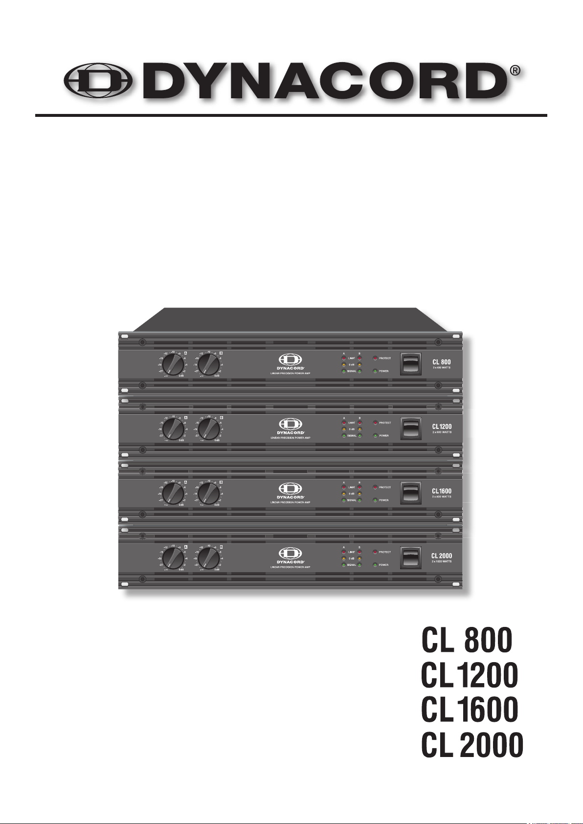
OWNER‘S MANUAL
Page 2

.......................
.......................
.......................
.......................
WICHTIGE SICHERHEITSHINWEISE
WICHTIGE SERVICEHINWEISE
AUSPACKEN & GARANTIE
INSTALLATIONSHINWEISE
TECHNISCHE DATEN
ABMESSUNGEN
Page 3
The lightning ash with arrowhead symbol, within an
to constitute a risk of electric shock to persons.
The exclamation point within an equilateral triangle is
the literature accompanying the appliance.
4.
with one wider than the other. A grounding type plug has two blades and a third grounding prong. The wide
To completely disconnect this equipment from the AC Mains, disconnect the power plug from the AC receptacle.
The mains plug of the power supply cord shall remain readily operable.
These servicing instructions are for use by quali ed personnel only. To reduce the risk of
The minimum distance between parts carrying mains voltage and any accessible metal piece (metal enclosure),
Altering the circuitry without prior consent or advice is not legitimate.
Any work security regulations that are applicable at the location where the appliance is being serviced have to be
All instructions concerning the handling of MOS - circuits have to be observed.
Page 4

With buying a DYNACORD CL-SERIES power ampli er you have chosen an appli-
weight and power dissipation.
fast, signal-dependent operating voltage switching, which results in doubling the regular supply voltage
when needed. Compared to Class-AB power amps, Class-H power amps generate by far less power
the risk of the output transistors being damaged by electrical energy back-feed. The power outputs are
front panel. CL-Series power amps provide the opportunity for retro tting an internal analogue signal
4
Page 5

x 330mm
(up to the cabinet’s top ventilation louvers) for air circulation between the rear of the power
to “MAINS OPERATION AND RESULTING TEMPERATURE”).
warmer environment. In that case operation is only permissible after the appliance has gained the
Page 6
the power amps while input signals are interrupted as well, preventing the connected
Whatever caused the fault – e.g. a short-circuited speaker cable – needs to be reme-
rming the correct operation of the protection circuitry.
Page 7
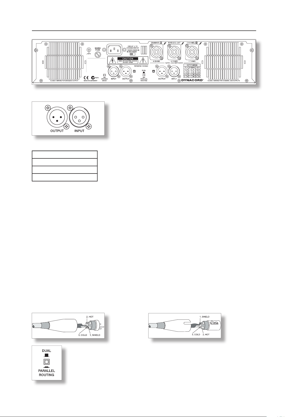
the shield connects all metal enclosure parts and therefore ef ciently eliminates the introduction of ex-
ternal interference – mostly noise and hum.
type connector pin-assignment
XLR (male)
XLR (female)
when the selector switch is set to PARALLEL. However, individually controlling the
volume of both channels is still possible via the corresponding level controls A and B.
If the selector switch is set to DUAL, the audio signals of channels A and B are
independently ampli ed.
If the selector switch is set to DUAL, the audio signals of channels A and B are
Although having XLR-type output connectors, some mixing console models provide unbalanced
to the setting of the Power-ON switch.
Page 8
A plastic cover to prevent inadvertent erroneous
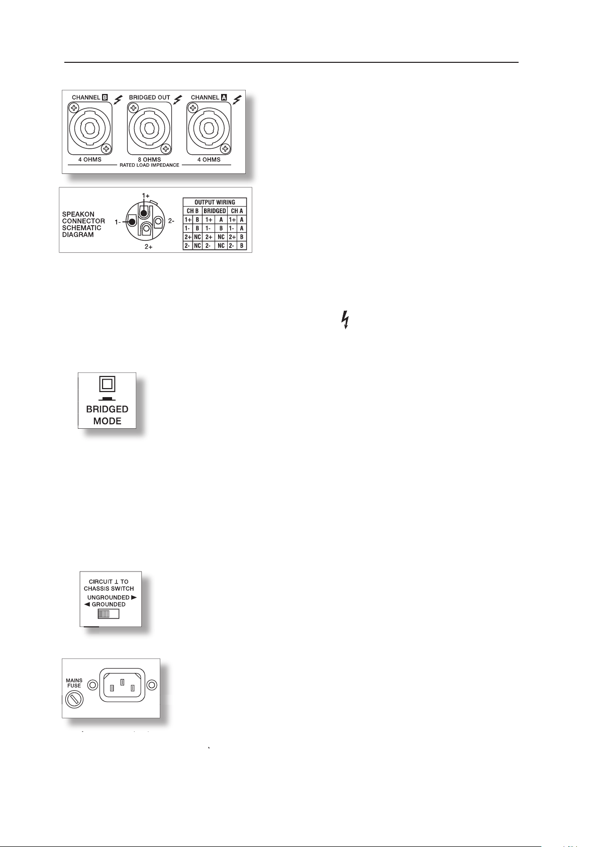
With the BRIDGED-MODE switch being engaged, using the channel A input
for audio signal feed is mandatory, since input B provides no function. While
the ampli er of channel A operates as usual, the audio signal is internally
inverted and routed to the ampli er of channel B. Both amps – A and B – now
work in push-pull operation to provide doubled output voltage at the
BRIDGED-OUT connector.
to its GROUNDED position is recommended. If the power ampli er is operated
together with appliances with differing ground potentials, set the switch to its
type with identical amperage, voltage and blow characteristics. If the mains
to applicable safety regulations, plus that its diameter corresponds to the power
to the mains. Using mains cords with smaller diameters results in higher leakage and consequently re-
At 100V and 120V units the mains fuse is installed internally. This is fore safety reasons. In case of a
fuse blows more often, please contact an authorized service centre.
the cabinets, please make sure to mind the Low- and High channels’ speci c pin-assignments!
WARNING:
terminals are hazardous live and present a risk of electric shock to the user.
Page 9
ventilation efforts necessary.
[V]
[A]
[W]
4,4
495
1/3 Max. Output Power @ 4Ω
4,6
1/8 Max. Output Power @ 4Ω
490
1/8 Max. Output Power @ 4Ω
425
1/8 Max. Output Power @ 4Ω
1/8 Max. Output Power @ 4Ω
430
1/8 Max. Output Power @ 4Ω
404
440
Alert (Alarm) Mode (-3dB) @ 4Ω
4,9
1/8 Max. Output Power @ 2Ω
4,8
1/8 Max. Output Power @ 2Ω
4,2
1/8 Max. Output Power @ 2Ω
4,2
[V]
[A]
[W]
1/3 Max. Output Power @ 4Ω
1/8 Max. Output Power @ 4Ω
400
1/8 Max. Output Power @ 4Ω
455
1/8 Max. Output Power @ 4Ω
1/8 Max. Output Power @ 4Ω
450
1/8 Max. Output Power @ 4Ω
Alert (Alarm) Mode (-3dB) @ 4Ω
4710
1/8 Max. Output Power @ 2Ω
419
1/8 Max. Output Power @ 2Ω
4,1
454
1/8 Max. Output Power @ 2Ω
4,4
494
(2) VDE-Noise
(3) pink-Noise EN60065 / 7. Edition
The following factors allow direct proportional calculation of the mains current Imain for different mains supply voltages:
Page 10
[V]
[A]
[W]
440
1/3 Max. Output Power @ 4Ω
1/8 Max. Output Power @ 4Ω
1/8 Max. Output Power @ 4Ω
1/8 Max. Output Power @ 4Ω
420
1/8 Max. Output Power @ 4Ω
1/8 Max. Output Power @ 4Ω
4,1
455
470
Alert (Alarm) Mode (-3dB) @ 4Ω
4000
1/8 Max. Output Power @ 2Ω
4,5
1/8 Max. Output Power @ 2Ω
1/8 Max. Output Power @ 2Ω
[V]
[A]
[W]
1/3 Max. Output Power @ 4Ω
1/8 Max. Output Power @ 4Ω
4,0
1/8 Max. Output Power @ 4Ω
4,4
446
1/8 Max. Output Power @ 4Ω
4,8
1/8 Max. Output Power @ 4Ω
4,5
1/8 Max. Output Power @ 4Ω
4,8
Alert (Alarm) Mode (-3dB) @ 4Ω
1/8 Max. Output Power @ 2Ω
1/8 Max. Output Power @ 2Ω
1/8 Max. Output Power @ 2Ω
(2) VDE-Noise
(3) pink-Noise EN60065 / 7. Edition
The following factors allow direct proportional calculation of the mains current Imain for different mains supply voltages:
Page 11
Page 12

WICHTIGE SICHERHEITSHINWEISE
WICHTIGE SERVICEHINWEISE
AUSPACKEN & GARANTIE
INSTALLATIONSHINWEISE
Page 13

WICHTIGE SICHERHEITSHINWEISE
führen können.
Verwenden Sie zur Reinigung ausschließlich ein trockenes Tuch.
Achten Sie darauf, dass die Belüftungsöffnungen nicht versperrt sind. Beachten Sie bei der Installation des Geräts die
Anweisungen des Herstellers.
Anschlüssen, das Kabel zu knicken oder einzuklemmen.
Verwenden Sie ausschließlich vom Hersteller dafür vorgesehenes Zubehör und Erweiterungen.
Verwenden Sie zusammen mit dieser Komponente nur vom Hersteller dazu vorgesehene oder andere geeignete Lastkarren,
Trennen Sie das Gerät bei Gewitter oder, wenn Sie es über einen längeren Zeitraum nicht verwenden, vom Stromnetz.
Wenden Sie sich im Servicefall an einen quali zierten Servicebetrieb. In folgenden Fällen sollten Sie sich unbedingt
Trennen Sie den Netzstecker von der Wandsteckdose, um das Gerät komplett vom Stromnetz zu trennen.
WICHTIGE SERVICEHINWEISE
ACHTUNG:
trenntransformator zu verwenden.
Vor einem Umbau mit Nachrüstsätzen, Umschaltung der Netzspannung oder sonstigen Modi kationen ist das Gerät
4.
verbunden sind (sekundär), betragen 6 mm und sind unbedingt einzuhalten.
Page 14

Sie haben sich mit einer Endstufe der CL-SERIE von DYNACORD für ein
triebssicherheit.
wird bei Endstufen mit Class H Technik erheblich weniger Verlustleistung bei gleicher Ausgangsleistung
Ausgangsleistung.
Ausgang geschützt. Eine Beschädigung der Endtransistoren durch Rückeinspeisung elektrischer Energie
wird durch die Back-EMF Schutzschaltung verhindert. Beim Softstart werden die Leistungsausgänge
Ansprechen von Netzsicherungen.
zur Nachrüstung einer analogen Signalprozessorkarte mit Frequenzweichen- und Filterfunktionen.
zu 2 Ohm und im Brückenbetrieb bis zu minimal 4 Ohm eingesetzt werden.
Page 15

AUSPACKEN & GARANTIE
to-Rear“. Geräte mit umgekehrter Luftführung sollen möglichst nicht im gleichen Rack/Schrank verbaut
werden. Für den Einbau in Gehäuse und Gestellschränke ist zu beachten, dass eine ausreichende
vorzusehen. Oberhalb des Schrankes soll ein freier Raum von mindestens 100mm für die Entlüftung zur
Verfügung stehen. Da beim Betrieb die Temperatur im Gehäuse- oder Schrank bis zu 40°C ansteigen
Achtung:
Vibrationen.
Wenn die Endstufe direkt von einem kalten an einen warmen Ort gebracht wird, kann sich Feuchtigkeit
von einer autorisierten Servicestelle überprüfen, bevor Sie es weiterverwenden.
Page 16

zeige nicht leuchtet, ist das Gerät nicht mit dem Stromnetz verbunden, oder die
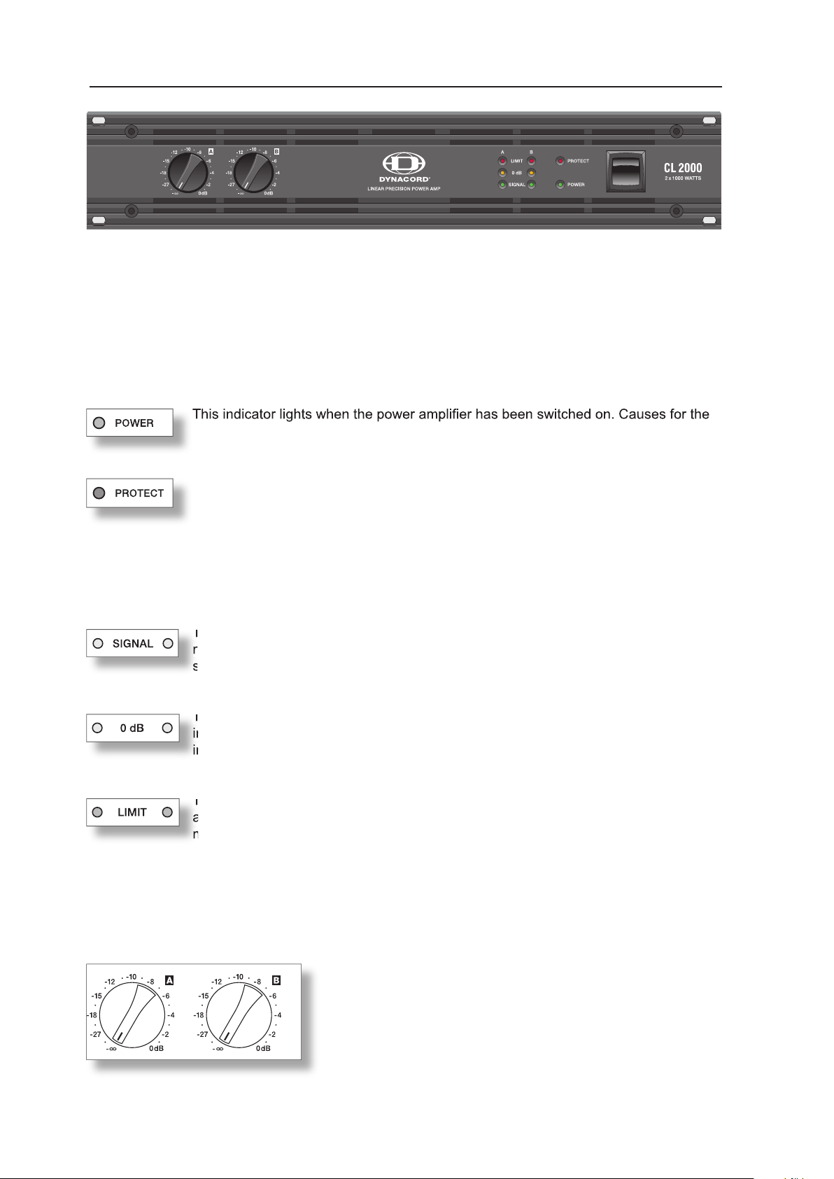
Wenn die PROTECT-Anzeige au euchtet, hat eine der internen Schutzschaltungen
wie Übertemperatur, Kurzschluss, Back-EMF, Hochfrequenz am Ausgang usw, ange-
fe sich selbständig wieder in den normalen Betriebszustand schaltet.
verlischt diese
Anzeige.
Limitern sehr hilfreich sein.
tisch, da der
faktor von ca. 1% ausregeln kann. Leuchtet diese LED jedoch dauerhaft, sollte die
zerrungen in vorgeschalteten Mischpulten sollten diese
werden. Die Beschriftung zeigt unmittelbar die Reglerdämp-
fung mit der die intern festgelegte Verstärkung verändert wird.
rechts auf der Frontblende wird das Gerät eingeschaltet. Eine Softstart-
Während dieser Verzögerung leuchtet die PROTECT LED und die Lüfter laufen mit maximaler Ge-
von Lautsprecherleitungen oder Ansprechen einer Schutzschaltung
trieben wird. Eine höhere Eingangsspannung hat keine Erhöhung der Spitzenausgangs-
spannung zur Folge. Die 0dB Anzeige kann auch bei der Einstellung von externen
Page 17

Ausgangsleistungen können bedenkenlos gegeneinander ausge-
tauscht werden, die Weichen brauchen aufgrund der konstanten
Verstärkung über die gesamte Baureihe, nicht nachjustiert werden.
Als NF-Verbindung wählen Sie am besten symmetrisch ausgelegte Kabel (2 Signaladern + Schirm-
trischer Signalführung alle metallischen Gehäuse und verhindert dadurch lückenlos ein Einkoppeln von
XLR-Steckerbelegung
XLR (male)
XLR (male)
XLR (female)
wird dadurch wesentlich vereinfacht. Endstufen mit unterschiedlichen
Ausgangssteckverbindung XLR Stecker vorgesehen sind. Falls ein Mischpult mit unsymmetrischen
Ausgängen verwendet wird, müssen an den Endstufeneingangsbuchsen PIN1 und PIN3 miteinander
Wird aus unsymmetrisch beschalteten Geräten über PIN3 (b, -, „kalt“) und PIN2 (a, +, „heiß“)
Page 18

Anschlussfehler zu vermeiden. Entfernen Sie den
ACHTUNG!
Zum bequemen Anschluss von 2-Weg Lautsprechern
verbunden.
werden. Der Input B hat dann keine Funktion.Die Endstufe im Kanal A wird
ACHTUNG: Im Bridged-Betrieb können sehr hohe Spannungen am BRIDGED OUT Ausgang
wird, sollte der Schalter in Stellung GROUNDED stehen. Wird die Endstufe
tung zur Folge.
Warnung:
Page 19

Die vom Stromnetz aufgenommene Leistung wird in Ausgangsleistung für die Lautsprecher und in
Wärme umgewandelt. Die Differenz aus aufgenommener Leistung und abgegebener Leistung nennt
zeigt die Verlustleistung bei verschiedenen Betriebszuständen. Die Spalte BTU/hr
zeigt die abgegebene Wärmemenge je Stunde.
[V]
[A]
[W]
4,4
495
1/3 Max. Output Power @ 4Ω
4,6
1/8 Max. Output Power @ 4Ω
490
1/8 Max. Output Power @ 4Ω
425
1/8 Max. Output Power @ 4Ω
474
1/8 Max. Output Power @ 4Ω
430
1/8 Max. Output Power @ 4Ω
404
440
Alert (Alarm) Mode (-3dB) @ 4Ω
4,9
1/8 Max. Output Power @ 2Ω
4,8
1/8 Max. Output Power @ 2Ω
4,2
1/8 Max. Output Power @ 2Ω
4,2
Sinusaussteuerung (1kHz)
VDE-Rauschen
[V]
[A]
[W]
1/3 Max. Output Power @ 4Ω
1/8 Max. Output Power @ 4Ω
400
1/8 Max. Output Power @ 4Ω
455
1/8 Max. Output Power @ 4Ω
1/8 Max. Output Power @ 4Ω
450
1/8 Max. Output Power @ 4Ω
Alert (Alarm) Mode (-3dB) @ 4Ω
4710
1/8 Max. Output Power @ 2Ω
419
1/8 Max. Output Power @ 2Ω
4,1
454
1/8 Max. Output Power @ 2Ω
4,4
494
Page 20

[V]
[A]
[W]
440
1/3 Max. Output Power @ 4Ω
1/8 Max. Output Power @ 4Ω
1/8 Max. Output Power @ 4Ω
1/8 Max. Output Power @ 4Ω
420
1/8 Max. Output Power @ 4Ω
1/8 Max. Output Power @ 4Ω
4,1
455
470
Alert (Alarm) Mode (-3dB) @ 4Ω
4000
1/8 Max. Output Power @ 2Ω
4,5
1/8 Max. Output Power @ 2Ω
1/8 Max. Output Power @ 2Ω
Sinusaussteuerung (1kHz)
VDE-Rauschen
[V]
[A]
[W]
1/3 Max. Output Power @ 4Ω
1/8 Max. Output Power @ 4Ω
4,0
1/8 Max. Output Power @ 4Ω
4,4
446
1/8 Max. Output Power @ 4Ω
4,8
1/8 Max. Output Power @ 4Ω
4,5
1/8 Max. Output Power @ 4Ω
4,8
Alert (Alarm) Mode (-3dB) @ 4Ω
1/8 Max. Output Power @ 2Ω
1/8 Max. Output Power @ 2Ω
1/8 Max. Output Power @ 2Ω
Page 21

Page 22

.......................
.......................
Page 23

triangle équilatéral a pour but d’alerter l’utilisateur
Veuillez lire ces instructions.
4.
fonctionne pas normalement, ou s’il est tombé.
fonctionner en étant branché sur le secteur.
4.
Toutes les instructions concernant la manipulation des circuits MOS doivent être respectées.
Page 24

En achetant un ampli cateur de puissance DYNACORD CL-SERIES, vous avez choisi
fusibles secteur ne sautent.
ventilateurs à trois vitesses (arrêt/lente/rapide) très performants garantissent une stabilité thermique
type SPEAKON. Toujours à l’arrière, se trouve un sélecteur de masse (Ground-Lift), qui aide à éliminer
type SPEAKON. Toujours à l’arrière, se trouve un sélecteur de masse (Ground-Lift), qui aide à éliminer
fonctionnement normal, tous les amplis de puissance CL peuvent gérer des charges aussi faibles que
fonctionnement normal, tous les amplis de puissance CL peuvent gérer des charges aussi faibles que
Page 25

(jusqu’aux ouies de ventilation situées en haut du meuble) pour permettre la circulation de
Attention :
trop élevée, les excès de poussière et les vibrations.
Page 26

jusqu’à une THD (Distorsion harmonique totale) d’approximativement 1%. Par
–6 dB. La graduation en dB donne une indication immédiate
fonction Soft-Start élimine les crêtes provoquées par l’appel de courant à l’allumage, ce qui par la même
tensions de sorties plus fortes. De plus, ce témoin est très pratique lors du réglage
Page 27

XLR (
XLR (femelle)
Les connecteurs d’entrée des canaux A et B sont reliés électriquement en parallèle
lorsque le sélecteur est réglé sur PARALLEL. Toutefois, le contrôle séparé des
lorsque le sélecteur est réglé sur PARALLEL. Toutefois, le contrôle séparé des
deux canaux est toujours possible via le contrôle de niveau A ou B.
Si le sélecteur est réglé sur DUAL, les signaux audio des canaux et A et B sont
ampli és indépendamment.
Page 28

type SPEAKON.
ATTENTION !
Ampli cation) lors de l’utilisation de câbles Speakon à 4
ls.
Si le bouton BRIDGED MODE est engagé, l’utilisation de l’entrée du canal A
pour le signal audio est obligatoire, puisque l’entrée B ne fonctionne pas. Alors
que l’ampli cateur du canal A fonctionne normalement, le signal audio est
inversé en interne et dirigé vers l’ampli cateur du canal B. Les deux amplis,
A et B, fonctionnent alors en push-pull pour fournir une tension de sortie
double sur le connecteur BRIDGED OUT.
ATTENTION : Des tensions très fortes peuvent être présentes sur le connecteur BRIDGED OUT
vente agréé. Le cordon secteur hautes-performances fourni avec votre
teur fourni pour brancher l’ampli de puissance sur le secteur, si c’est possible. L’utilisation d’un cordon
ATTENTION :
Page 29

ALIMENTATION SECTEUR ET TEMPÉRATURE RÉSULTANTE
fonctionnement. La colonne „BTU/h“ indique la chaleur diffusée par heure.
ALIMENTATION SECTEUR ET TEMPÉRATURE RÉSULTANTE
[V]
[A]
[W]
4,4
495
1/3 Max. Output Power @ 4Ω
4,6
1/8 Max. Output Power @ 4Ω
490
1/8 Max. Output Power @ 4Ω
425
1/8 Max. Output Power @ 4Ω
474
1/8 Max. Output Power @ 4Ω
430
1/8 Max. Output Power @ 4Ω
404
440
Alert (Alarm) Mode (-3dB) @ 4Ω
4,9
1/8 Max. Output Power @ 2Ω
4,8
1/8 Max. Output Power @ 2Ω
4,2
1/8 Max. Output Power @ 2Ω
4,2
[V]
[A]
[W]
1/3 Max. Output Power @ 4Ω
1/8 Max. Output Power @ 4Ω
400
1/8 Max. Output Power @ 4Ω
455
1/8 Max. Output Power @ 4Ω
1/8 Max. Output Power @ 4Ω
450
1/8 Max. Output Power @ 4Ω
Alert (Alarm) Mode (-3dB) @ 4Ω
4710
1/8 Max. Output Power @ 2Ω
419
1/8 Max. Output Power @ 2Ω
4,1
454
1/8 Max. Output Power @ 2Ω
4,4
494
(2) Bruit VDE
Page 30

[V]
[A]
[W]
440
1/3 Max. Output Power @ 4Ω
1/8 Max. Output Power @ 4Ω
1/8 Max. Output Power @ 4Ω
1/8 Max. Output Power @ 4Ω
420
1/8 Max. Output Power @ 4Ω
1/8 Max. Output Power @ 4Ω
4,1
455
470
Alert (Alarm) Mode (-3dB) @ 4Ω
4000
1/8 Max. Output Power @ 2Ω
4,5
1/8 Max. Output Power @ 2Ω
1/8 Max. Output Power @ 2Ω
(2) Bruit VDE
ALIMENTATION SECTEUR ET TEMPÉRATURE RÉSULTANTE
[V]
[A]
[W]
1/3 Max. Output Power @ 4Ω
1/8 Max. Output Power @ 4Ω
4,0
1/8 Max. Output Power @ 4Ω
4,4
446
1/8 Max. Output Power @ 4Ω
4,8
1/8 Max. Output Power @ 4Ω
4,5
1/8 Max. Output Power @ 4Ω
4,8
Alert (Alarm) Mode (-3dB) @ 4Ω
1/8 Max. Output Power @ 2Ω
1/8 Max. Output Power @ 2Ω
1/8 Max. Output Power @ 2Ω
Page 31

2 Ω
4 Ω
2 Ω
4 Ω
2 Ω
4 Ω
2 Ω
4 Ω
THD = 1%, 1kHz , Dual Channel
400W
240W
THD < 0,1%, 20Hz … 20kHz
250W
450W
450W
2200W
2700W
480W
270W
410W
THD = 1%, 1kHz
2200W
2000W
THD = 1%, 1kHz
THD =1%, half power @ 4 ohms
Voltage Gain
THD at rated output power
20 kΩ
25 V/µs
Ampli er
A-weighted
Audio limiters, High temperature, DC, HF, Back-EMF,
Ambient Temperature Limits
483 x 88,1 x 386,8
Weight
load in Dual Mode or 4
load in Bridged Mode.
- Ampli er at rated conditions, both channels driven, 8
load, unless otherwise speci ed.
Page 32

Page 33

ABMESSUNGEN / DIMENSIONS
ABMESSUNGEN / DIMENSIONS (in mm)
Page 34

Page 35

Page 36

Telex Communications Inc., 12000 Portland Ave. South, Burnsville, MN 55337, Phone: +1 952-884-4051, FAX: +1 952-884-0043
www.dynacord.de
 Loading...