

Page 1
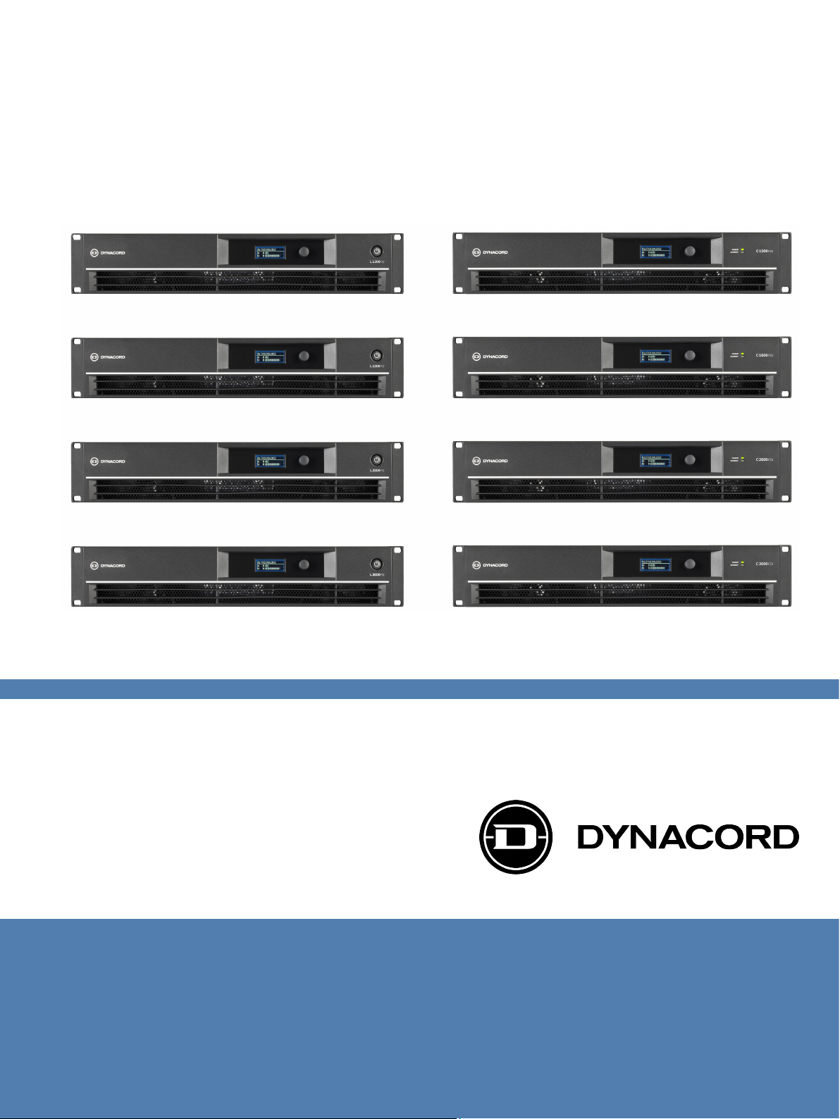
L Series and C Series FIR-Drive Power
Amplifiers
en | Installation manual
Page 2

Page 3

L Series and C Series FIR-Drive Power
Amplifiers
Table of contents
Table of Contents | en 3
1
1.1 Safety messages explained 5
1.2 Important safety instructions 5
1.3 Safety precautions 7
1.4 FCC 8
1.5 Notices 8
2
2.1 Manual purpose 9
2.2 Digital document 9
2.3 Intended audience 9
2.4 Short Information 9
3
3.1 Application area 11
3.2 Features 11
3.3 Unpacking and inspection 11
3.4 Scope of delivery 11
4
5
5.1 Operating voltage 14
5.2 Power 14
5.2.1 L Series 14
5.2.2 C Series 14
5.3 Mounting 15
5.4 Ventilation 15
6
6.1 L Series amplifier 17
6.2 C Series amplifier 18
6.3 Fan cooling 18
6.4 Groundlift 19
6.5 USB B connector 19
6.6 Power remote 19
6.7 Power on delay 19
6.8 GPI/GPO 19
6.9 Power outputs 20
6.9.1 L Series amplifier 20
6.9.2 C Series amplifier 21
6.10 Audio input cabling 22
6.10.1 Audio input cabling for XLR-type connectors 22
6.10.2 Audio input cabling for Euroblock-type connectors 23
7
7.1 Amplifier and DSP control 24
7.2 DSP control menu 24
7.3 Factory presets 26
8
8.1 C Series direct drive load capability 34
8.2 Mains operation & resulting temperature 35
Safety 5
About this manual 9
System overview 11
Planning information 13
Installation 14
Controls, indicators and connections 17
Power amplifier menu navigation 24
Technical data 29
Bosch Sicherheitssysteme GmbH Installation manual 2017.10 | 02 | F.01U.327.801
Page 4

4 en | Table of Contents
L Series and C Series FIR-Drive Power
Amplifiers
8.3 Block diagrams 38
8.4 Dimensions 40
2017.10 | 02 | F.01U.327.801 Installation manual Bosch Sicherheitssysteme GmbH
Page 5
!
!
!
L Series and C Series FIR-Drive Power
Amplifiers
Safety | en 5
1
1.1
Safety
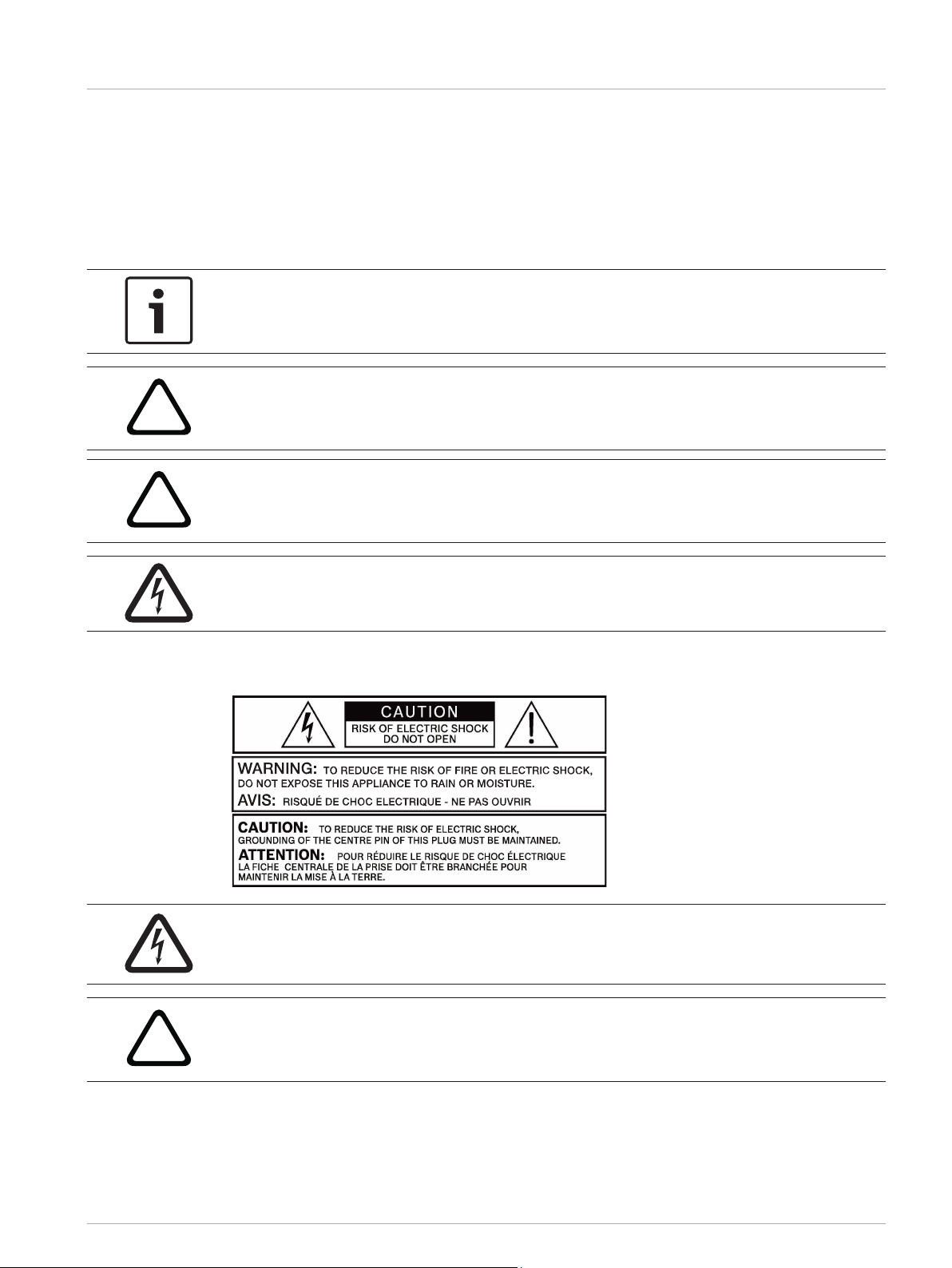
Safety messages explained
Four types of signs can be used in this manual. The type is closely related to the effect that
may be caused if it is not observed. These signs - from least severe effect to most severe
effect - are:
Notice!
Containing additional information. Usually, not observing a ‘notice’ does not result in damage
to the equipment or personal injuries.
Caution!
The equipment or the property can be damaged, or persons can be lightly injured if the alert
is not observed.
Warning!
The equipment or the property can be seriously damaged, or persons can be severely injured
if the alert is not observed.
Danger!
Not observing the alert can lead to severe injuries or death.
1.2
Important safety instructions
Danger!
The lightning symbol inside a triangle notifies the user of high-voltage, uninsulated lines and
contacts inside the devices that could result in fatal electrocution if touched.
Warning!
An exclamation mark inside a triangle refers the user to important operating and service
instructions in the documentation for the equipment.
1. Read these safety notes.
2. Keep these safety notes in a safe place.
Heed all warnings.
3.
4. Observe all instructions.
Bosch Sicherheitssysteme GmbH Installation manual 2017.10 | 02 | F.01U.327.801
Page 6
!
6 en | Safety
L Series and C Series FIR-Drive Power
Amplifiers
5. Do not operate the device in close proximity to water.
6. Use only a dry cloth to clean the unit.
7.
Do not cover any ventilation slots. Always refer to the manufacturer's instructions when
installing the device.
8. Do not install the device close to heaters, ovens, or other heat sources.
9. Note: The device must only be operated via the mains power supply with a safety ground
connector. Do not disable the safety ground connection function of the supplied power
cable. If the plug of the supplied cable does not fit your mains socket, please contact
your electrician.
10. Ensure that it is not possible to stand on the mains cable. Take precautions to ensure the
mains cable cannot become crushed, particularly near the device connector and mains
plug.
11. Only use accessories/extensions for the device that have been approved by the
manufacturer.
12. Unplug the device if there is risk of lightning strike or in the event of long periods of
inactivity. However, this does not apply if the device is to be used as part of an
evacuation system!
13. Have all service work and repairs performed by a trained customer service technician
only. Service work must be carried out immediately following any damage such as
damage to the mains cable or plug, if fluid or any object enters the device, if the device
has been used in rain or become wet, or if the device has been dropped or no longer
works correctly.
14. Please ensure that no dripping water or spray can penetrate the inside of the device. Do
not place any objects filled with fluids, such as vases or drinking vessels, on top of the
device.
15. To ensure the device is completely free of voltage, unplug the device from the power
supply.
16. When installing the device, ensure that the plug is freely accessible.
17. Do not place any sources of open flame, such as lit candles, on top of the device.
18. This PROTECTION CLASS I device must be connected to a MAINS socket with a safety
ground connection.
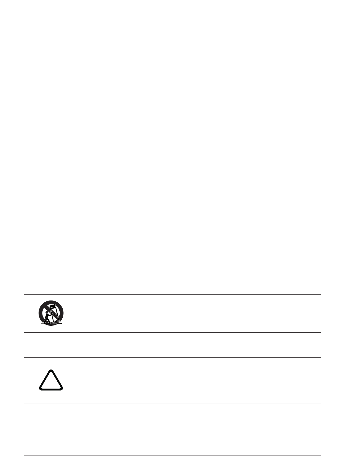
Caution!
Use only manufacturer-approved carts, stands, brackets, or tables that you acquired together
with the device. When using carts to move the device, make sure the transported equipment
and the cart itself cannot tip over or cause injury or material damage.
IMPORTANT SERVICE INFORMATION
Caution!
This service information is for use by qualified service personnel only. To avoid the risk of
electric shock, do not perform any maintenance work that is not described in the operating
instructions unless you are qualified to do so. Have all service work and repairs performed by
a trained customer service technician.
1. Repair work on the device must comply with the safety standards specified in EN 60065
(VDE 0860).
2. A mains isolating transformer must be used during any work for which the opened device
is connected to and operated with mains voltage.
2017.10 | 02 | F.01U.327.801 Installation manual Bosch Sicherheitssysteme GmbH
Page 7
L Series and C Series FIR-Drive Power
Amplifiers
3. The device must be free of any voltage before performing any alterations with upgrade
sets, switching the mains voltage, or performing any other modifications.
4. The minimum distance between voltage-carrying parts and metal parts that can be
touched (such as the metal housing) or between mains poles is 3 mm, and must be
observed at all times.
5.
The minimum distance between voltage-carrying parts and circuit parts that are not
connected to the mains (secondary) is 6 mm, and must be observed at all times.
6. Special components that are marked with the safety symbol in the circuit diagram (note)
must only be replaced with original parts.
7. Unauthorized changes to the circuitry are prohibited.
8. The protective measures issued by the relevant trade organizations and applicable at the
place of repair must be observed. This includes the properties and configuration of the
workplace.
9. Observe the guidelines with respect to handling MOS components.
Danger!
SAFETY COMPONENT (MUST BE REPLACED BY ORIGINAL PART)
Safety | en 7
1.3
Safety precautions
Speaker system damage and protection of human beings
Power amps provide extremely high power output that might be dangerous for human beings
as well as for the connected speaker systems. High output voltages can damage or even
destroy the connected speaker systems, especially, when the amplifier is operated in bridged
mode. Prior to connecting any loudspeakers, make sure to check the speaker system’s
specifications for continuous and peak power handling capacities. Even if amplification has
been reduced through lowering the input level controls on the amplifier’s front panel, it is still
possible to achieve full power output with a sufficiently high input signal.
Danger!
Danger at the loudspeaker/power outputs
Power amplifiers are capable of producing dangerously high voltage output that is present at
the output connectors.
To protect yourself from electric shock, do not touch any blank speaker cables during
operation of the power amp.
Danger!
The terminals marked with a lightning bolt are hazardous live and the external wiring
connected to these terminals requires installation by an instructed person or the use of ready-
made leads of cords.
Danger!
In case of using the amplifier with speakers including a primary tapped transformer, it is
possible that during operation shock hazard voltages may be present at the taps of the
transformer.
Therefore, the taps have to be insulated sufficiently in accordance with applicable safety
regulations.
Bosch Sicherheitssysteme GmbH Installation manual 2017.10 | 02 | F.01U.327.801
Page 8
8 en | Safety
L Series and C Series FIR-Drive Power
Amplifiers
1.4
FCC
IMPORTANT: Do not modify this unit! Changes or modifications not expressly approved by the
manufacturer could void the user’s authority, granted by the FCC, to operate the equipment.
Notice!
This equipment has been tested and found to comply with the limits for a Class B digital
device, pursuant to Part 15 of the FCC Rules. These limits are designed to provide reasonable
protection against harmful interference in a residential installation. This equipment generates,
uses and can radiate radio frequency energy and, if not installed and used in accordance with
the instructions, may cause harmful interference to radio communications. However, there is
no guarantee interference will not occur in a particular installation.
If this equipment does cause harmful interference to radio or television reception or receive
audible interference from radio, television or communications equipment, which can be
determined by turning the equipment off and on. The user is encouraged to try to correct the
interference by one or more of the following measures:
• Reorient or relocate the receiving antenna.
Increase the separation between the equipment and receiver.
•
• Connect the equipment into an outlet on a circuit different from that to which the
receiver is connected.
• Consult the dealer or an experienced radio/TV/communications equipment technician.
1.5
Notices
Old electrical and electronic appliances
Electrical or electronic devices that are no longer serviceable must be collected separately and
sent for environmentally compatible recycling (in accordance with the European Waste
Electrical and Electronic Equipment Directive).
To dispose of old electrical or electronic devices, you should use the return and collection
systems put in place in the country concerned.
Copyright and disclaimer
All rights reserved. No part of this document may be reproduced or transmitted in any form by
any means, electronic, mechanical, photocopying, recording, or otherwise, without the prior
written permission of the publisher. For information on getting permission for reprints and
excerpts, contact Dynacord.
The content and illustrations are subject to change without prior notice.
2017.10 | 02 | F.01U.327.801 Installation manual Bosch Sicherheitssysteme GmbH
Page 9

L Series and C Series FIR-Drive Power
Amplifiers
About this manual | en 9
2
2.1
2.2
2.3
2.4
About this manual
Manual purpose
The purpose of this manual is to provide information required for installing, configuring,
operating and maintaining the L Series FIR-Drive Power Amplifier and C Series FIR-Drive
Power Amplifier hardware products.
Read through this manual to familiarize yourself with the safety information, features, and
applications before you use these products.
Digital document
This manual is available as a digital document in the Adobe Portable Document Format (PDF).
You can find information about Dynacord products on the product related information at
www.dynacord.com.
Intended audience
This manual is intended for installers, operators, and users of L/C series powered amplifier
systems.
Short Information
The following table lists products in a family, with CTN (Commercial Type Number) and
identifying product name DESCRIPTION.
CTN Description
L Series
L1300FD-AU DSP power amplifier 2x650W AU
L1300FD-CN DSP power amplifier 2x650W CN
L1300FD-EU DSP power amplifier 2x650W EU
L1300FD-JP DSP power amplifier 2x650W JP
L1300FD-UK DSP power amplifier 2x650W UK
L1300FD-US DSP power amplifier 2x650W US
L1800FD-AU DSP power amplifier 2x950W AU
L1800FD-CN DSP power amplifier 2x950W CN
L1800FD-EU DSP power amplifier 2x950W EU
L1800FD-JP DSP power amplifier 2x950W JP
L1800FD-UK DSP power amplifier 2x950W UK
L1800FD-US DSP power amplifier 2x950W US
L2800FD-AU DSP power amplifier 2x1400W AU
L2800FD-CN DSP power amplifier 2x1400W CN
L2800FD-EU DSP power amplifier 2x1400W EU
L2800FD-JP DSP power amplifier 2x1400W JP
Bosch Sicherheitssysteme GmbH Installation manual 2017.10 | 02 | F.01U.327.801
Page 10

10 en | About this manual
CTN Description
L2800FD-UK DSP power amplifier 2x1400W UK
L2800FD-US DSP power amplifier 2x1400W US
L3600FD-AU DSP power amplifier 2x1800W AU
L3600FD-CN DSP power amplifier 2x1800W CN
L3600FD-EU DSP power amplifier 2x1800W EU
L3600FD-JP DSP power amplifier 2x1800W JP
L3600FD-UK DSP power amplifier 2x1800W UK
L3600FD-US DSP power amplifier 2x1800W US
C Series
C1300FDi-AU DSP power amplifier 2x650W, install AU
C1300FDi-CN DSP power amplifier 2x650W, install CN
C1300FDi-EU DSP power amplifier 2x650W, install EU
L Series and C Series FIR-Drive Power
Amplifiers
C1300FDi-JP DSP power amplifier 2x650W, install JP
C1300FDi-UK DSP power amplifier 2x650W, install UK
C1300FDi-US DSP power amplifier 2x650W, install US
C1800FDi-AU DSP power amplifier 2x950W, install AU
C1800FDi-CN DSP power amplifier 2x950W, install CN
C1800FDi-EU DSP power amplifier 2x950W, install EU
C1800FDi-JP DSP power amplifier 2x950W, install JP
C1800FDi-UK DSP power amplifier 2x950W, install UK
C1800FDi-US DSP power amplifier 2x950W, install US
C2800FDi-AU DSP power amplifier 2x1400W, install AU
C2800FDi-CN DSP power amplifier 2x1400W, install CN
C2800FDi-EU DSP power amplifier 2x1400W, install EU
C2800FDi-JP DSP power amplifier 2x1400W, install JP
C2800FDi-UK DSP power amplifier 2x1400W, install UK
C2800FDi-US DSP power amplifier 2x1400W, install US
C3600FDi-AU DSP power amplifier 2x1800W, install AU
C3600FDi-CN DSP power amplifier 2x1800W, install CN
C3600FDi-EU DSP power amplifier 2x1800W, install EU
C3600FDi-JP DSP power amplifier 2x1800W, install JP
C3600FDi-UK DSP power amplifier 2x1800W, install UK
C3600FDi-US DSP power amplifier 2x1800W, install US
2017.10 | 02 | F.01U.327.801 Installation manual Bosch Sicherheitssysteme GmbH
Page 11
!
L Series and C Series FIR-Drive Power
Amplifiers
System overview | en 11
3
3.1
3.2
3.3
System overview
Application area
The L Series and C Series power amplifier are designed to power professional loudspeaker
system in live and fix installed audio applications such as concerts, clubs, sports venues,
HOWs and many other applications.
Features
L Series
•
Live performance DSP amplifier
Fully integrated professional speaker processing with FIR Drive technology
•
• Market leading acoustic performance and rock solid reliability
• True 2 ohm stability
• Intuitive system control software, makes setup and control easy
C Series
• Installation DSP amplifier, Euroblock connectors
• Fully integrated professional speaker processing with FIR Drive technology
• Market leading acoustic performance and rock solid reliability
• Low Z and 70/100V operation and power saving standby mode
• Intuitive system control software, makes setup and control easy
Unpacking and inspection
3.4
Carefully open the packaging and take out the power amplifier. Inspect the power amp’s
enclosure for damages that might have happened during transportation. Each amplifier is
examined and tested in detail before leaving the manufacturing site to ensure that it arrives in
perfect condition at your place. Please inform the transport company immediately, if the
power amplifier shows any damage. Being the addressee, you are the only person who can
claim damages in transit. Keep the cardboard box and all packaging materials for inspection
by the transport company.
Keeping the cardboard box including all packing materials is also recommended, if the power
amplifier shows no external damages.
Caution!
Do not ship the power amp in any other but its original packaging.
When shipping the power amp, make sure to always use its original box and packaging
materials. Packing the power amplifier like it was packed by the manufacturer guarantees
optimum protection from transport damage.
Scope of delivery
Quantity Component
1 DSP amplifier
1 Mains cord
1 USB cable
Bosch Sicherheitssysteme GmbH Installation manual 2017.10 | 02 | F.01U.327.801
Page 12

12 en | System overview
Quantity Component
1 Installation manual
1 Safety instruction card
Table 3.1: L Series
Quantity Component
1 DSP amplifier
1 Mains cord
1 USB cable
1 Euroblock GPIO connector 6 pole
1 Euroblock output connector 4 pole
2 Euroblock input connectors 3 pole
1 Power remote connector 2 pole
1 Installation manual
L Series and C Series FIR-Drive Power
Amplifiers
1 Safety instruction card
Table 3.2: C Series
Keep the original invoice that states the purchase/delivery date in a safe place.
2017.10 | 02 | F.01U.327.801 Installation manual Bosch Sicherheitssysteme GmbH
Page 13

L Series and C Series FIR-Drive Power
Amplifiers
Planning information | en 13
4
Planning information
Ensure the following:
• You make use of manufacturer specified installation materials.
•
No liquids can spill into or on the products.
• Installation is in a clean environment free of dust.
• The ventilation airflow of the 19" units is not obstructed.
• There is a mains power outlet of sufficient rating close to the intended location of the
products.
• Sufficient free space and access at the rear of the 19" units for connectors and wiring.
To find current user documentation, firmware, or software visit our product related
information at www.dynacord.com.
Bosch Sicherheitssysteme GmbH Installation manual 2017.10 | 02 | F.01U.327.801
Page 14
14 en | Installation
L Series and C Series FIR-Drive Power
Amplifiers
5
5.1
5.2
5.2.1
Installation
Operating voltage
The power amplifier receives its power supply via the MAINS IN connector. Only the provided
power cord may be used. During installation, always separate the power amplifier from the
mains. Connect the power amplifier only to a mains network, which corresponds to the
requirements indicated on the type plate.
Power
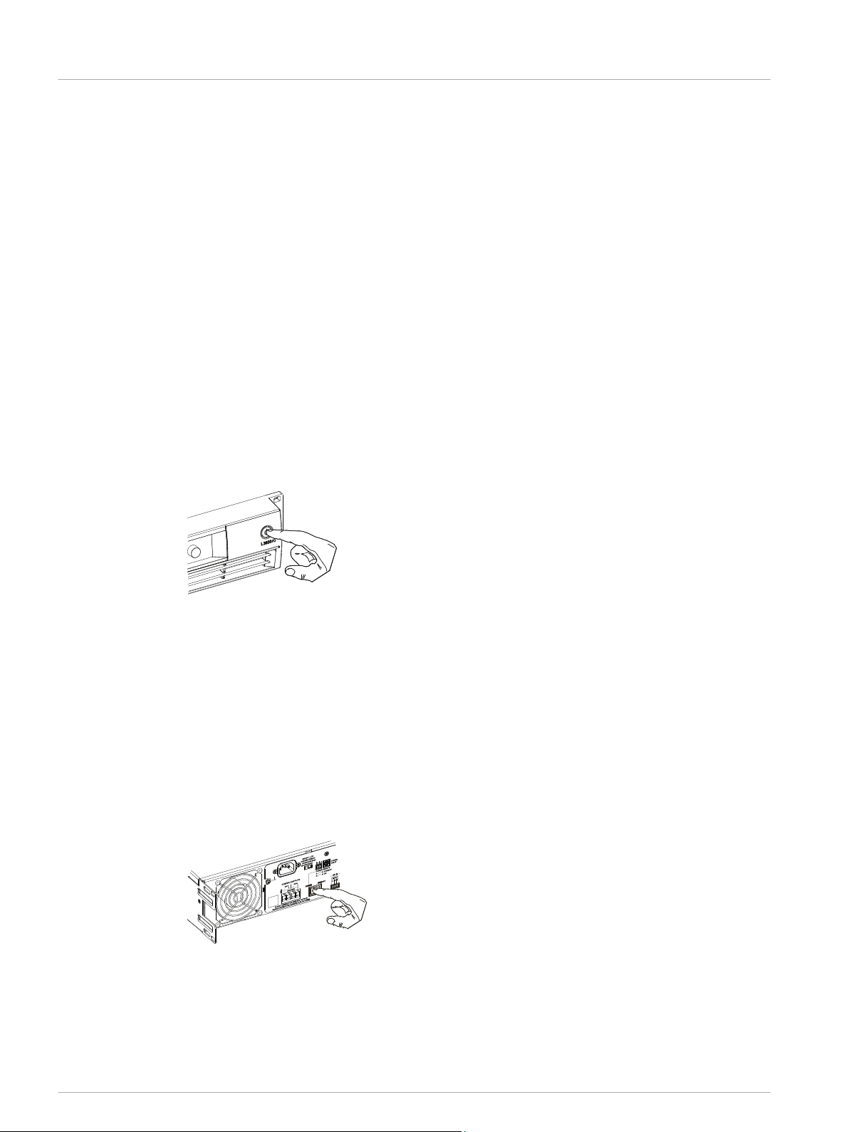
The L Series power button is located on the front of the amplifier panel. The C Series power
switch is located on the rear of the amplifier panel.
L Series
The Power button on the front panel separates the power amp from the mains. Pressing the
Power button turns on the power amp. A soft start circuit compensates mains inrush current
peaks and thus prevents triggering AC mains fuse when switching on the amplifier. Speaker
system switch-on is delayed by approximately two seconds via output relays, effectively
suppressing any possible power-on noise, which otherwise might be heard through the
loudspeakers.
5.2.2
Figure 5.1: Power button on the front panel (L Series)
C Series
The Power/Standby switch on the rear panel is used to turn on the power to the amplifier or
put the amplifier into standby mode. To separate the amplifier from the mains it is required to
disconnect the mains power connection. A soft start circuit compensates mains inrush current
peaks and thus prevents the automatic cutout of the mains from reacting when switching on
the power amplifier. Speaker system switch-on is delayed by approximately two seconds via
output relays, effectively suppressing any possible power-on noise, which otherwise might be
heard through the loudspeakers. PROTECT-LED lights up and fans are at high speed during
this delay. This indicates all protections are working fine.
Figure 5.2: Mains switch on the rear panel (C Series)
2017.10 | 02 | F.01U.327.801 Installation manual Bosch Sicherheitssysteme GmbH
Page 15

L Series and C Series FIR-Drive Power
Amplifiers
Installation | en 15
5.3
5.4
Mounting
L Series and C Series amplifiers have been designed for installation in a conventional 19-inch
rack case. Attach the power amp with its frontal rack mount ears using four screws and
washers as shown in the illustration.
Additionally securing the amplifier at the rear becomes necessary, if the rack case in which the
power amplifier has been installed will be transported. Failure to do so may result in damage
to the power amplifier as well as to the rack case. Attach the power amp as shown in the
illustration using four case nuts and screws. Brackets for securing the power amplifier are
available as accessories.
Figure 5.3: Mounting powered an amplifier in a rack, front (left) and rear (right) showing optional RMK-15
Ventilation
As with all Dynacord
obviously because there is more cold air outside of the rack case than inside. The power
amplifier remains cooler and dissipating the developing waste heat in a specific direction gets
easier. In general, setting up or mounting the power amplifier has to be done in a way that
fresh air can enter unhindered at the front and exhausted air can exit at the rear. When
installing the power amp in a case or rack system, attention should be paid to these details to
provide sufficient ventilation. Allow for an air duct of at least 60 mm x 330 mm between the
rear panel of the power amplifier and the inner wall of the cabinet/rack case. Make sure that
the duct reaches up to the cabinets or the rack case’s top ventilation louvers. Leave room of at
least 100 mm above the cabinet/rack case for ventilation. Since temperatures inside of the
cabinet/rack case can easily rise up to 40 °C during operation of the power amp, it is
mandatory to bear in mind the maximum allowable ambient temperature for all other
appliances installed in the same cabinet/rack case.
Figure 5.4: Power amplifier ventilation
power amps with fan cooling, the airflow direction is front-to-rear,
Bosch Sicherheitssysteme GmbH Installation manual 2017.10 | 02 | F.01U.327.801
Page 16

!
16 en | Installation
L Series and C Series FIR-Drive Power
Caution!
Blocking/closing the power amp's ventilation louvers is not permissible. Without sufficient
cooling/ventilation, the power amplifier may automatically enter protect mode.
Keep ventilation louvers free from dust to ensure unhindered airflow.
Notice!
Do not use the power amplifier near heat sources, like heater blowers, stoves, or any other
heat radiating devices.
Notice!
Do not use
or exceed +40°C.
Dynacord power amplifiers in an environment where temperatures are below 0°C
Amplifiers
For fixed amplifier installations in a device control room that incorporate a central air-cooling
system or air conditioners, calculating the maximum heat emission may be necessary.
See also
– Mains operation & resulting temperature, page 35
2017.10 | 02 | F.01U.327.801 Installation manual Bosch Sicherheitssysteme GmbH
Page 17

1
2
3
2
3
4
5
6
Bosch Security Systems BV
Torenallee 49, NL-5617BA Eindhofen
Quality by Bosch
Made in China
S/N: PPBTTTTDDDLLLLSSSS
TL-1.3K2-EU
Mat/N: F01U312382
N633
230V~50-60 Hz / 550W
1
77
6
L Series and C Series FIR-Drive Power
Amplifiers
Controls, indicators and connections | en 17
6
6.1
Controls, indicators and connections
L Series amplifier
Front view
1. LCD - LCD control and monitoring interface.
2.
Encoder knob - Scroll through the DSP menu and select the available choices. Push the
encoder knob to enter the DSP menu.
3. POWER - AC button for turning the power ON or OFF. The LCD screen lights up when the
power is turned on.
Rear view
1. FAN - Exhaust air vent for amplifier cooling. Do not obstruct!
2.
MAINS IN - AC mains input socket.
3. Groundlift switch (CIRCUIT ⊥ TO CHASSIS SWITCH) - Switch allows eliminating hum
noise loops.
4. USB type B connector.
5. Power amp outputs Speakon (CHANNEL A, CHANNEL B)
6. Audio inputs (INPUT A, INPUT B) directly linked to the outputs.
7. Audio outputs (OUTPUT A, OUTPUT B) directly linked to the inputs.
Bosch Sicherheitssysteme GmbH Installation manual 2017.10 | 02 | F.01U.327.801
Page 18

1 2 3
4
1 2 3 4 5 6 7
8 9
10
HIGH-Z MODE
BRIDGET
1 x 70 V
1 x 900 W
Bosch Security Systems BV
Tor
enallee 49, NL-5617BA Eindhofen
Quality by Bosch
Made in China
S/N: PPBTTTTDDDLLLLSSSS
RC-1.3K2-EU
Mat/N: F01U314181
N633
230V~50-60 Hz / 550W
18 en | Controls, indicators and connections
L Series and C Series FIR-Drive Power
Amplifiers
6.2
C Series amplifier
Front view
1. LCD - LCD control and monitoring interface.
2. Encoder knob - Scroll through the DSP menu and select the available choices. Push the
encoder knob to enter the DSP menu.
3. POWER - Power on/off indicator.
4. STANDBY - standby indicator.
Rear view
6.3
1. FAN - Exhaust air vent for amplifier cooling. Do not obstruct!
2. MAINS IN - AC mains input socket.
3.
Groundlift switch (CIRCUIT ⊥ TO CHASSIS SWITCH) - Switch allows eliminating hum
noise loops.
4. POWER REMOTE connector
5. POWER ON DELAY - power on delay selection switch.
6. USB type B connector.
7. GPI/GPO
8. POWER OUTPUTS
9. POWER/STANDBY switch
10. INPUT - audio inputs for channels A or B (CH A, CH B).
Fan cooling
The power amplifier has two fans. The fans are switched in three performance-optimized
levels, for example they are not running permanently but the speed of the fans is controlled
The temperatures of the power amp's channels are supervised and monitored individually.
depending on the temperature. That in return ensures very silent operation during idle state.
2017.10 | 02 | F.01U.327.801 Installation manual Bosch Sicherheitssysteme GmbH
Page 19

L Series and C Series FIR-Drive Power
Amplifiers
Controls, indicators and connections | en 19
6.4
6.5
6.6
Groundlift
The ground lift switch allows eliminating hum noise loops. When operating the power amplifier
together with other equipment in a rack case, setting the switch to the GROUNDED position is
recommended. Set the switch to UNGROUNDED, when the power amplifier is operated
together with appliances with differing ground potentials.
USB B connector
The USB B connector is used for remote control configuration and firmware updates. With the
included USB AB cable you can connect the amplifier directly to a PC. To connect multiple
amplifiers use an external USB-hub or range extender.
For firmware updates, amplifier control software, and product related information visit our
website: www.dynacord.com/software
.
Power remote
POWER REMOTE (standby mode) provides a simple way to remotely power-on/off the power
amplifier. Leaving the pins of POWER REMOTE socket open the appliance power is switched
on. When connecting the pins the appliance enters standby mode.
6.7
6.8
Power on delay
The ON DELAY switch at the amplifier rear panel allows selecting the power on delay time.
The On delay table shows possible switch settings and corresponding delay times.
ON DELAY Delay time (in s) ON DELAY Delay time (in s)
0 0.52 8 1.05
1 0.59 9 1.15
2 0.63 A 1.25
3 0.69 B 1.40
4 0.75 C 1.49
5 0.84 D 1.55
6 0.90 E 1.61
7 0.95 F 1.69
Table 6.1: On delay
GPI/GPO
C Series amplifiers include two GPIs and one GPO.
Bosch Sicherheitssysteme GmbH Installation manual 2017.10 | 02 | F.01U.327.801
Page 20

20 en | Controls, indicators and connections
GPI:
The GPI is used to change between two internal device presets. If the GPI 1 or GPI 2 is set to
GND potential, the preset is switched from the original selected preset to the preset set for
GPI 1 or GPI 2.
GPO:
The GPO is designed as a potential-free changeover switch (relay).
If power is on, GPO pin 3 and GPO pin 1 are shorted.
If the amplifier is turned off or a fault condition appears, GPO pin 3 and GPO pin 2 are
shorted.
L Series and C Series FIR-Drive Power
Amplifiers
6.9
6.9.1
Power outputs
L Series amplifier
Cabling with two Speakon-type connectors in Normal mode
The first possibility in Normal mode is to use the two Speakon-type connectors, whereas
speakers have to be connected to pins 1+ and 1– of the sockets. The correct connection is
also indicated at the amplifiers rear panel.
Figure 6.1: Normal mode
Bi-Amp cabling in Normal mode with Speakon-type connector
The second possibility for connecting the speakers when the power amplifier is operated in
Normal mode is to only use the Speakon-type connector CHANNEL A and to connect one
speaker cabinet to pins 1+ and 1–, as described above and the second cabinet to pins 2+ and
2–. Pins 2+ and 2– are only assigned at Speakon-type connector of CHANNEL A. Proceeding
like this facilitates the cabling of speaker systems that are used in active 2-way operation (BiAmp). The correct connection is also indicated at the amplifiers rear panel.
Figure 6.2: Bi-Amp cabling in Normal mode
Speakon CHANNEL B Speakon CHANNEL A
1+ 1- Connector 1+ 1- 2+ 2-
B+ B- Signal A+ A- B+ B-
Table 6.2: Speaker connection using Speakon A and B connectors
2017.10 | 02 | F.01U.327.801 Installation manual Bosch Sicherheitssysteme GmbH
Page 21

!
L Series and C Series FIR-Drive Power
Amplifiers
Cabling with Speakon-type connector in Bridged mode
In Bridged mode both amp channels work in push-pull operation to provide doubled output
voltage.
In bridged mode operation speaker connection has to be established using pins 1+ and 2- of
the Speakon socket CHANNEL A. The correct connection is also indicated at the amplifiers
rear panel.
Figure 6.3: Bridged mode
Speakon CHANNEL A
Connector 1+ 2-
Controls, indicators and connections | en 21
6.9.2
Signal Bridged+ Bridged-
Table 6.3: Speaker connection using Speakon A
Caution!
In Bridged mode operation, it is not allowable for the load connected to all below a value of 4
ohms. Extremely high voltages can be present at the output. The connected speaker systems
must be able to handle such voltages. Make sure to completely read and fully observe power
rating specifications of the speaker systems to be used and to check them against the output
power capacity of the power amp.
Property damage and/or personal injury may occur.
C Series amplifier
Cabling with Euroblock-type connector in Normal mode
See illustration for connecting speakers in Normal mode. The correct connection is also
indicated at the amplifiers rear panel.
Figure 6.4: Normal mode
Cabling with Speakon-type connector in Bridged mode
In Bridged mode both amp channels work in push-pull operation to provide doubled output
voltage.
Bosch Sicherheitssysteme GmbH Installation manual 2017.10 | 02 | F.01U.327.801
Page 22

!
1, SHIELD
3,
COLD
2, HOT
22 en | Controls, indicators and connections
In Bridged mode operation speaker connection has to be established using pins 1+ and 2-, see
illustration. The correct connection is also indicated at the amplifiers rear panel.
Figure 6.5: Bridged mode
Caution!
In Bridged mode operation, it is not allowable for the load connected to all below a value of 4
ohms. Extremely high voltages can be present at the output. The connected speaker systems
must be able to handle such voltages. Make sure to completely read and fully observe power
rating specifications of the speaker systems to be used and to check them against the output
power capacity of the power amp.
Property damage and/or personal injury may occur.
L Series and C Series FIR-Drive Power
Amplifiers
6.10
6.10.1
Audio input cabling
Audio input cabling for XLR-type connectors
Inputs INPUT A and INPUT B are electronically balanced. The pin-assignment of XLRF-type
connectors is in accordance with the IEC standard 268.
Figure 6.6: Balanced connection of input
Whenever possible, using balanced audio signal feeds at the input of the power amplifier is
always preferred. Unbalanced connections should only be used if the cables are very short and
no interfering signals are to be expected in the vicinity of the power amplifier. In this case,
bridging the screen (shielding) and the pin of the inverting input inside of the connector is
mandatory. Otherwise, a 6 dB drop in level could result. Due to their immunity against
external interference sources, such as dimmers, mains connections, HF-control lines, etc.,
using balanced cabling and connections is always preferable.
2017.10 | 02 | F.01U.327.801 Installation manual Bosch Sicherheitssysteme GmbH
Page 23

TO SHIELD
3, COLD
2,
HOT
JUMPER
FRO
M COLD
3, COLD 2, HOT
1, SHIELD
L Series and C Series FIR-Drive Power
Amplifiers
Figure 6.7: Unbalanced connection of input
Next to its input connector, each channel provides an individual XLR-type connector (OUTPUT
A or OUTPUT B), which is connected in parallel to allow for comfortably daisy-chaining the
audio signal for the connection of additional audio equipment.
Controls, indicators and connections | en 23
6.10.2
Figure 6.8: Balanced connection of output (Daisy-Chain)
Audio input cabling for Euroblock-type connectors
Inputs are electronically balanced. Whenever possible, using balanced audio signal feeds at
the input of the power amplifier is always preferred. Unbalanced connections should only be
used if the cables are very short and no interfering signals are to be expected in the vicinity of
the power amplifier. In this case, bridging the screen (shielding) and the pin of the inverting
input inside of the connector is mandatory. Otherwise, a 6 dB drop in level could result. Due
to their immunity against external interference sources, such as dimmers, mains connections,
HF-control lines, etc., using balanced cabling and connections is always preferable.
Figure 6.9: Balanced/unbalanced connection of input
Bosch Sicherheitssysteme GmbH Installation manual 2017.10 | 02 | F.01U.327.801
Page 24

24 en | Power amplifier menu navigation
L Series and C Series FIR-Drive Power
Amplifiers
7
7.1
Power amplifier menu navigation
Amplifier and DSP control
An integrated amplifier and DSP control menu allows the user to select multiple system
settings on the power amplifier. When the power amplifier is powered on the home screens
appears.
Figure 7.1: LCD control and monitoring interface
Preset No: Preset Name
A: 0 dB (Default) Range: Mute, -80 dB to 0 dB
B: 0 dB (Default) Range: Mute, -80 dB to 0 dB
Table 7.1: Home screen
Preset No: Preset Name: If a recalled preset is edited the letter E is shown. Edited presets
can be stored in one of the 50 User Presets.
Channel A or B: Icons in the home screen lines 2 and 3 indicate that the original loaded preset
has been modified.
G = GEQ (Graphical Equalizer) in use
• E = EQ/PEQ (Parametric Equalizer) in use
D = Delay in use
•
Accessing the amplifier DSP control menu
To access the amplifier DSP controls menu, do the following:
1. Push the encoder knob.
The DSP Control menu appears.
2. Turn the encoder knob to scroll through the menu items.
3. Push the encoder knob to select the menu item you want to modify.
The focus advances to the next parameter set.
4. Turn the encoder knob to scroll through the parameters.
5. Using the encoder knob, adjust the parameters to the desired value.
6. Push the encoder knob to confirm the modified parameter.
The parameter is changed to the current setting.
7. Repeat steps 2 through 6 to modify additional DSP and system settings.
8. Select EXIT to return to the home screen.
7.2
DSP control menu
In the DSP menu structure "U_" indicates user defined presets and "F_" indicates factory
settings. When firmware is updated the factory settings may change. Refer to the latest
release notes for further information.
2017.10 | 02 | F.01U.327.801 Installation manual Bosch Sicherheitssysteme GmbH
Page 25

Preset F1 --- F8/10**
Store Preset
U1 --- U50 U1 --- U50
Startup:
Last
F1 -- F8/10*
U1 --- U50
AMP Setup
Mode:
Normal
Bridged
Routing A:
In A In A
Routing B:
In B In A In B
In B In A+B
In A+B
DSP Edit
EQ A
EQ B
Delay A: 0 ms 0 --- 650 ms 0 --- 680 ft
Delay B: 0 ms
0 --- 207 m
GEQ A: OFF ON
GEQ B: OFF
LP/HP/Xover Freq. 30 - 300 Hz
Parameter: Unlinked Linked
GPI Config* I1:
None
*C Series
I2: U1 (Linear Dual)
None F1 --- F8/10** only!
F1 --- F8/10** U1 --- U50
U1 --- U50
Load Monitor
Imp. A:
Imp. B:
Lock
Front Control On / Off
Preset On / Off
AMP Setup On / Off
DSP Edit On / Off
USB On / Off
Reset On / Off
Lock
Pin Code:
0 0 0 0
Options
Name: Untitled
Brightness: 100%
Dim Level: 50%
Dim-Time: Off
Contrast: 5
Delay unit: ms
Ambient: 20 °C / 68 °F
Reset
Default settings? NO
YES NO
YES
Info
Name: Untitled
Model: L / C Series
Firmware: x.x.xx
Ontime: h:m
Standby time*: h:m
-20 °C --- +60 °C
Erase User Presets?
Meter - Feet - ms
days : h, after 1000 h
Load Preset
0 --- 100 %
0 --- 10
0 --- 100 %
Off / 10 --- 60 sec.
x.x Ohm / Open / Shorted / Invalid
x.x Ohm / Open / Shorted / Invalid
U1 (Linear Dual)
** See preset table
Dependent on preset
EQ 1-5: Enable (On/Off), Type (PEQ, Loshelv, Hishelv, Hipass, Lopass),
Frequency (20Hz - 20kHz), Gain (-18dB - +12dB), Quality (0.4 - 40.0), Slope
(6dB/Oct, 12dB/Oct)
L Series and C Series FIR-Drive Power
Amplifiers
Power amplifier menu navigation | en 25
Figure 7.2: DSP control menu
Bosch Sicherheitssysteme GmbH Installation manual 2017.10 | 02 | F.01U.327.801
Page 26

26 en | Power amplifier menu navigation
Notice!
Controlling multiple amplifiers via Dynacord control software: It is recommend to use a powered
USB hub if the user wishes to control amplifiers with one cable to their computer. USB range
extenders can also be used to remotely position the software control interface longer distances
from the amplifiers.
Due to the great number of USB hubs and extenders, it is not possible to verify and test all
brands and models for use with this product.
To find current user documentation, firmware, or software visit our product related
information at www.dynacord.com.
L Series and C Series FIR-Drive Power
Amplifiers
7.3
Factory presets
L Series and C Series amplifiers have a selection of factory presets on board. These are
generic settings to be used as a starting point for configuration that do not require a
dedicated speaker setting, but only some basic sound adjustments. The following content is
based on the first release, future firmware updates might include additional or updated
settings.
Name Input Routing Parameters
F01 Linear Dual In A > Out A In B >Out B All flat, no links
F02 Linear Mono A In A > Out A In A >Out B All flat, no links
F03 Stereo Linked In A > Out A In B >Out B All flat, CH A & B linked
F04 Sub & Top #1 In A > Out A In A > Out B BW18dB x-over @ 100Hz
F05 Sub Stereo #1 In A > Out A In B >Out B BW18dB Lo-Pass @ 100Hz
F06 Top Stereo #1 In A > Out A In B > Out B BW18dB Hi-Pass @ 100Hz
F07 Sub & Top #2 In A > Out A In A > Out B LR24dB x-over @ 100Hz
F08 Sub Stereo #2 In A > Out A In B > Out B LR24dB Lo-Pass@ 100Hz
F09 Top Stereo #2 In A > Out A In B > Out B LR24dB Hi-Pass @ 100Hz
F10 LPN Stereo In A > Out A In B > Out B LPN filter for enhanced LF
Table 7.2: L Series factory presets
Name Input Routing Parameters
F01 Linear Dual In A > Out A In B >Out B All flat, no links
F02 Linear Mono A In A > Out A In A >Out B All flat, no links
F03 Stereo Linked In A > Out A In B >Out B All flat, CH A & B linked
F04 HP50Hz-Dual In A > Out A In B >Out B Hi-Pass 18dB @ 50Hz
F05 HP50Hz-Mono In A > Out A In A >Out B Hi-Pass 18dB @ 50Hz
F06 HP50Hz-Stereo In A > Out A In B >Out B Hi-Pass 18dB @ 50Hz, CH A &
B linked
F07 LPN Stereo In A > Out A In B >Out B LPN filter for enhanced LF
C1300FDi
2017.10 | 02 | F.01U.327.801 Installation manual Bosch Sicherheitssysteme GmbH
Page 27

L Series and C Series FIR-Drive Power
Amplifiers
Name Input Routing Parameters
F08 70V Single In A > Out A&B Bridged Mode! Hi-Pass 18dB @ 50Hz
C1800FDi
F08 70V Dual In A > Out A In B > Out B Hi-Pass 18dB @ 50Hz
F09 70V Mono In A > Out A In A > Out B Hi-Pass 18dB @ 50Hz
F10 100V Single In A > Out A&B Bridged Mode! Hi-Pass 18dB @ 50Hz
C2800FDi and C3600FDi
F08 70V Dual In A > Out A In B > Out B Hi-Pass 18dB @ 50Hz
F09 70V Mono In A > Out A In A > Out B Hi-Pass 18dB @ 50Hz
F10 100V Dual In A > Out A In B > Out B Hi-Pass 18dB @ 50Hz
Table 7.3: C Series factory presets
Edit factory preset: When a factory preset is recalled and edited this is marked with an E.
Edited presets can be stored in one of the 50 User Presets.
Bridged configuration: If the amplifier is used in a bridged configuration, only channel A is
shown.
Preset: Is used to load or store a device preset. In addition to 10 factory presets there are also
50 user presets available.
AMP Setup: Is used to select between normal operation and bridged operation.
Power amplifier menu navigation | en 27
Notice!
Bridge operation requires different cabling.
Routing: Is used to select input signal routing for channels A and B: A, B, or A+B (sum).
DSP Edit:
EQ (Equalizer) for channel A & B: five band adjustable parameters are as shown in table.
Delay set the audio delay per channel A or B individually up to 650 ms. Units can be selected
in ms, meters, and feet in the Options.
GEQ this allows to bypass the Graphic EQ.
Notice!
The GEQ is only adjustable via remote control software.
LP/HP/Xover Freq: Factory presets with preset Hi-Pass/Lo-Pass or x-over frequencies is used
to modify the frequency parameter in the range of 30 Hz to 300 Hz.
Parameters: Select between channels A&B to be linked (all changes on CH A affect CH B) or
unlinked (changes on CH A do not affect CH B).
GPI Config (C Series only): Determines the two presets which can be toggled in-between
using the GPI contact.
Load Monitor: When signal is present the actual impedance per channel is displayed. Open
indicates that no speaker is connected. Shorted indicates a short circuit in the cabling. If the
signal is too low for a measurement it indicates Invalid.
Bosch Sicherheitssysteme GmbH Installation manual 2017.10 | 02 | F.01U.327.801
Page 28

28 en | Power amplifier menu navigation
Lock menu: Restricts unauthorized access by locking access to the amplifier in different
options. Using the lock feature affects changes to Front Control, Preset, AMP Setup, DSP Edit,
USB and Reset function with a 4-digit pin code. Use the encoder knob to view the menu/
function you want to lock.
Notice!
Keep your password in a safe place.
To unlock the amplifier if you've forgotten your password requires a service center activity.
L Series and C Series FIR-Drive Power
Amplifiers
Hint: If you lock the front panel control, all menus and parameters that could be accessed are
blocked. The amp can still be accessed from a computer via the USB port. Changes via GPI are not
affected by locking.
Notice!
If the amplifier is controlled via remote control software the first line in the display is showing
Remote Control and the front panel access is locked.
Options: User preferences for brightness, dim levels, contrast, delay units and ambient
temperature (for delay calculation) can be selected.
Reset: Returns the amplifier to the original factory settings. The option Erase User Presets
allows the user to keep or erase the user presets within the reset. Available options for this
selection are: No or YES.
Notice!
Performing a reset erases the user customized settings saved under the Store Preset option.
The 50 user customized settings in the Store Preset option return to <EMPTY>.
Info: Displays the name of the amplifier, the amplifier model (e.g. L3600FD), firmware version
and current ontime. C Series amplifiers have an additional parameter: Standby time.
For firmware updates, amplifier control software, and product related information visit our
website: www.dynacord.com/software
.
2017.10 | 02 | F.01U.327.801 Installation manual Bosch Sicherheitssysteme GmbH
Page 29

L Series and C Series FIR-Drive Power
Amplifiers
Technical data | en 29
8
Amplifier model L1300FD/C1300FDi
Load Impedance 2 Ω 2.6 Ω 4 Ω 8 Ω
Maximum Output Power, Single Channel 1100 W 950 W 660 W 350 W
Maximum Output Power, Dual Channel 1000 W 850 W 600 W 320 W
Maximum Output Power, Bridged - - 2000 W 1200 W
Maximum RMS Voltage Swing
THD = 1%, 1 kHz
Voltage Gain
Ref.1 kHz
THD at 450 W/4
MBW = 80 kHz, 1 kHz
IMD-SMPTE,
60 Hz, 7 kHz
DIM30,
3.15 kHz, 15 kHz
Maximum Input Level +21 dBu
Technical data
Ω
55.3 V
32.0 dB
< 0.05%
< 0.1%
< 0.05%
Crosstalk
ref. 1 kHz, at 100 W/4
Frequency Response
ref. 1 kHz
Input Impedance,
Active Balanced
Signal to Noise Ratio Amplifier,
A-weighted, ref to Max. Output Power @ 8
Output Noise
A-weighted
Output Stage Topology Class AB
Power Requirements 240 V, 230 V, 120 V or 100 V; 50 Hz to 60 Hz (factory configured)
Power Consumption
1/8 Maximum Output Power @ 4
Mains Fuse 240 V/230 V: T10AH; 120 V/100 V: T20AH
Protection Audio limiters, high temperature, DC, HF, Back-EMF, Peak current
,
Ω
,
Ω
Ω
limiters, Inrush current limiters, Turn on delay
10 Hz to 21 kHz (±1 dB)
< -80 dB
20 k Ω
>104 dB
< -68 dBu
550 W
Cooling Front-to-rear, 3-stage-fans
Ambient Temperature Limits +5°C to +40°C (40°F to +105°F)
Safety Class I
Bosch Sicherheitssysteme GmbH Installation manual 2017.10 | 02 | F.01U.327.801
Page 30

30 en | Technical data
L Series and C Series FIR-Drive Power
Amplifier model L1300FD/C1300FDi
Color Black
Dimensions (W x H x D), mm 483 x 88 x 462.4
Weight 12.9 kg (28.4 lb)
Amplifiers
Remote Power ON /GPIO
(C Series only)
Power remote via switch, delay time selectable
Floating relay contacts (show protect mode)
Inputs for preset selection
Signal Processing FIR Filters, Audio Limiters
Output delay per channel,
31 band GEQ per channel,
PEQ per channel,
Load impedance
Accessories RMK15 (rear rack mount kit), Multi Amplifier Remote Control
(MARC) software
Test signal for max. output power according IHF-A-202 (Dynamic-Headroom, burst 1 kHz/20
ms on/480 ms off/low level -20 dBu).
Amplifier model L1800FD/C1800FDi
Load Impedance 2 Ω 2.6 Ω 4 Ω 8 Ω
Maximum Output Power, Single Channel 1600 W 1300 W 950 W 480 W
Maximum Output Power, Dual Channel 1400 W 1200 W 850 W 450 W
Maximum Output Power, Bridged - - 2800 W 1700 W
Maximum RMS Voltage Swing
65.1 V
THD = 1%, 1 kHz
Voltage Gain
32.0 dB
Ref.1 kHz
THD at 600 W/4
Ω
< 0.05%
MBW = 80 kHz, 1 kHz
IMD-SMPTE,
< 0.1%
60 Hz, 7 kHz
DIM30
,
< 0.05%
3.15 kHz, 15 kHz
Maximum Input Level +21 dBu
Crosstalk
ref. 1 kHz, at 100 W/4
Frequency Response
Ω
,
10 Hz to 21 kHz (±1 dB)
< -80 dB
ref. 1 kHz
Input Impedance,
20 k Ω
Active Balanced
2017.10 | 02 | F.01U.327.801 Installation manual Bosch Sicherheitssysteme GmbH
Page 31

L Series and C Series FIR-Drive Power
Amplifiers
Amplifier model L1800FD/C1800FDi
Technical data | en 31
Signal to Noise Ratio Amplifier,
>105 dB
A-weighted, ref to Max. Output Power @ 8 Ω
Output Noise
,
< -68 dBu
A-weighted
Output Stage Topology Class AB
Power Requirements 240 V, 230 V, 120 V or 100 V; 50 Hz to 60 Hz (factory configured)
Power Consumption
1/8 Maximum Output Power @ 4
Ω
700 W
Mains Fuse 240 V/230 V: T12AH; 120 V/100 V: T25AH
Protection Audio limiters, high temperature, DC, HF, Back-EMF, Peak
current limiters, Inrush current limiters, Turn on delay
Cooling Front-to-rear, 3-stage-fans
Ambient Temperature Limits +5°C to +40°C (40°F to +105°F)
Safety Class I
Color Black
Dimensions
(W x H x D), mm 483 x 88 x 462.4
Weight 15.2 kg (33.5 lb)
Remote Power ON/GPIO
(C Series only)
Power remote via switch, delay time selectable
Floating relay contacts (show protect mode)
Inputs for preset selection
Signal Processing FIR Filters, Audio Limiters
Output delay per channel,
31 band GEQ per channel,
PEQ per channel,
Load impedance
Accessories RMK15 (rear rack mount kit), Multi Amplifier Remote Control
(MARC) software
Test signal for max. output power according IHF-A-202 (Dynamic-Headroom, burst 1 kHz/20
ms on/480 ms off/low level -20 dBu).
Amplifier model L2800FD/C2800FDi
Load Impedance 2 Ω 2.7 Ω 4 Ω 8 Ω
Maximum Output Power, Single Channel 2300 W 2000 W 1400 W 700 W
Maximum Output Power, Dual Channel 2200 W 1800 W 1300 W 650 W
Maximum Output Power, Bridged - - 4400 W 2600 W
Maximum RMS Voltage Swing
78.8 V
THD = 1%, 1 kHz
Bosch Sicherheitssysteme GmbH Installation manual 2017.10 | 02 | F.01U.327.801
Page 32

32 en | Technical data
L Series and C Series FIR-Drive Power
Amplifier model L2800FD/C2800FDi
Amplifiers
Voltage Gain
32.0 dB
Ref.1 kHz
THD at 900 W/4 Ω
< 0.05%
MBW = 80 kHz, 1 kHz
IMD-SMPTE,
< 0.1%
60 Hz, 7 kHz
DIM30
,
< 0.05%
3.15 kHz, 15 kHz
Maximum Input Level +21 dBu
Crosstalk
ref. 1 kHz, at 100 W/4
Frequency Response
Ω
,
10 Hz to 21 kHz (±1 dB)
< -80 dB
ref. 1 kHz
Input Impedance,
20 k Ω
Active Balanced
Signal to Noise Ratio Amplifier,
A-weighted, ref to Max. Output Power @ 8
Output Noise
,
Ω
>107 dB
< -68 dBu
A-weighted
Output Stage Topology Class H
Power Requirements 240 V, 230 V, 120 V or 100 V; 50 Hz to 60 Hz (factory configured)
Power Consumption
1/8 Maximum Output Power @ 4
Ω
700 W
Mains Fuse 240 V/230 V: T15AH; 120 V/100 V: T25AH
Protection Audio limiters, high temperature, DC, HF, Back-EMF, Peak current
limiters, Inrush current limiters, Turn on delay
Cooling Front-to-rear, 3-stage-fans
Ambient Temperature Limits +5°C to +40°C (40°F to +105°F)
Safety Class I
Color Black
Dimensions
(W x H x D), mm 483 x 88 x 462.4
Weight 16.2 kg (35.7 lb)
Remote Power ON/GPIO
(C Series only)
Power remote via switch, delay time selectable
Floating relay contacts (show protect mode)
Inputs for preset selection
2017.10 | 02 | F.01U.327.801 Installation manual Bosch Sicherheitssysteme GmbH
Page 33

L Series and C Series FIR-Drive Power
Amplifiers
Technical data | en 33
Amplifier model L2800FD/C2800FDi
Signal Processing FIR Filters, Audio Limiters
Output delay per channel,
31 band GEQ per channel,
PEQ per channel,
Load impedance
Accessories RMK15 (rear rack mount kit), Multi Amplifier Remote Control
(MARC) software
Test signal for max. output power according IHF-A-202 (Dynamic-Headroom, burst 1 kHz/20
ms on/480 ms off/low level -20 dBu).
Amplifier model L3600FD/C3600FDi
Load Impedance 2 Ω 2.7 Ω 4 Ω 8 Ω
Maximum Output Power, Single Channel 3200 W 2700 W 1800 W 950 W
Maximum Output Power, Dual Channel 3000 W 2500 W 1700 W 900 W
Maximum Output Power, Bridged - - 6000 W 3400 W
Maximum RMS Voltage Swing
90.6 V
THD = 1%, 1 kHz
Voltage Gain
32.0 dB
Ref.1 kHz
THD at 1200 W/4
Ω
< 0.05%
MBW = 80 kHz, 1 kHz
IMD-SMPTE,
< 0.1%
60 Hz, 7 kHz
DIM30
,
< 0.05%
3.15 kHz, 15 kHz
Maximum Input Level +21 dBu
Crosstalk
ref. 1 kHz, at 100 W/4
Frequency Response
Ω
,
10 Hz to 21 kHz (±1 dB)
< -80 dB
ref. 1 kHz
Input Impedance,
20 k Ω
Active Balanced
Signal to Noise Ratio Amplifier,
A-weighted, ref to Max. Output Power @ 8
Ω
>109 dB
Output Noise
,
< -68 dBu
A-weighted
Output Stage Topology Class H
Power Requirements 240 V, 230 V, 120 V or 100 V; 50 Hz to 60 Hz (factory configured)
Bosch Sicherheitssysteme GmbH Installation manual 2017.10 | 02 | F.01U.327.801
Page 34

34 en | Technical data
L Series and C Series FIR-Drive Power
Amplifier model L3600FD/C3600FDi
Amplifiers
Power Consumption
850 W
1/8 Maximum Output Power @ 4 Ω
Mains Fuse 240 V/230 V: T15AH; 120 V/100 V: T30AH
Protection Audio limiters, high temperature, DC, HF, Back-EMF, Peak current
limiters, Inrush current limiters, Turn on delay
Cooling Front-to-rear, 3-stage-fans
Ambient Temperature Limits +5°C to +40°C (40°F to +105°F)
Safety Class I
Color Black
Dimensions
(W x H x D), mm 483 x 88 x 462.4
Weight 18.2 kg (40.1 lb)
Remote Power ON/GPIO
(C Series only)
Power remote via switch, delay time selectable
Floating relay contacts (show protect mode)
Inputs for preset selection
Signal Processing FIR Filters, Audio Limiters
Output delay per channel,
31 band GEQ per channel,
PEQ per channel,
Load impedance
Accessories RMK15 (rear rack mount kit), Multi Amplifier Remote Control
(MARC) software
Test signal for max. output power according IHF-A-202 (Dynamic-Headroom, burst 1 kHz/20
ms on/480 ms off/low level -20 dBu).
8.1
C Series direct drive load capability
The direct drive load capability is a measure for the total wattage that can be driven in 70
V/100 V operation mode. A load capability value of 1250 watts means that this amplifier can
drive e.g. 50 loudspeakers at a voltage tab of 25 watts. The dB value in parentheses indicates
the delta to maximum modulation. In cases where the maximum modulation is not required
you can use the smaller amplifier model.
Model Load Capability Dual Channel Load Capability Bridge Mode
70V Operation 100V Operation 70V Operation 100V Operation
C3600FDi Not
recommended
C2800FDi 2 x 1250 W
(0.0 dB)
2 x 2500 W
1
(-1.5 dB)
2 x 2500 W
(-3.0 dB)
Not recommended
Not
recommended
1 x 1250 W
1
(0.0 dB)
1
2017.10 | 02 | F.01U.327.801 Installation manual Bosch Sicherheitssysteme GmbH
Page 35

L Series and C Series FIR-Drive Power
Amplifiers
Model Load Capability Dual Channel Load Capability Bridge Mode
C1800FDi 2 x 1250 W
C1300FDi Not available
Table 8.1: C Series direct drive load capability
1
This operation mode is not recommended due to the efficiency reasons. Please use the next
smaller amplifier for this mode.
2
Direct drive mode not available for this configuration.
Notice!
100 V: 2 x 2500 W means each channel of the amplifier may be loaded with a maximum 2500
W loudspeaker loads.
For example, 50x loudspeakers per channel, each loudspeaker with a power rating of 50
W/100 W.
(-1.5 dB)
Not available
2
2
Not
recommended
1 x 625 W
(0.0 dB)
Technical data | en 35
1 x 1250 W
1
(-1.5 dB)
Not available
2
8.2
Mains operation & resulting temperature
The power drawn from the mains network is converted into output power to feed the
connected loudspeaker systems and into heat. The difference between power consumption
and dispensed power is called power dissipation (Pd). The amount of heat resulting from
power dissipation might remain inside of a rack-shelf and needs to be diverted using
appropriate measures.
Mains operation & resulting temperature tables allow the determination of power supply and
cabling requirements. The tables are meant as auxiliary means for calculating temperatures
inside of a rack-shelf system/cabinet and the ventilation efforts necessary.
The column Pd lists the leakage power in relation to different operational states. The column
BTU/hr lists the dispensed heat amount per hour. Power consumption is direct proportional
for other mains voltages. The following conversion factors are meant for easy conversion: 100
V = 2.3; 120 V = 1.9; 240 V = 0.96.
Power consumption
C1300FDi
Output Power
Idle 230 0.5 43 - 43 146
1/8 Max. Output Power @ 8Ω
1/8 Max. Output Power @ 4Ω
U
mains
[V]
(2)
230 2.1 330 2 x 40 250 853
(2)
230 3.5 572 2 x 75 420 1435
I
mains
[A]
(5)
P
mains
[W]
P
out
[W]
Pd
[W]
(4)
BTU/hr
(3)
1/8 Max. Output Power @
(2)
2,66Ω
1/8 Max. Output Power @ 2Ω
1/8 Max. Output Power @ 4Ω
Rated Output Power @ 8Ω
(1)
230 4.7 808 2 x 10⁶ 596 2036
(2)
230 5.4 980 2 x 125 730 2490
(1)
230 3.9 630 2 x 75 480 1638
230 4.4 730 2 x 200 330 1126
Bosch Sicherheitssysteme GmbH Installation manual 2017.10 | 02 | F.01U.327.801
Page 36

36 en | Technical data
L Series and C Series FIR-Drive Power
Amplifiers
C1300FDi
Output Power
Rated Output Power @ 4Ω
(1)
1/8 70V/625W (8Ω) Bridged
(2)
Mode
Table 8.2: C1300FDi power consumption
C1800FDi
Output Power
Idle 230 0.4 51 - 51 174
1/8 Max. Output Power @ 8Ω
1/8 Max. Output Power @ 4Ω
(2)
(2)
1/8 Max. Output Power @
(2)
2,66Ω
1/8 Max. Output Power @ 2Ω
1/8 Max. Output Power @ 4Ω
Rated Output Power @ 8Ω
Rated Output Power @ 4Ω
(2)
(1)
(1)
(1)
U
mains
[V]
I
mains
[A]
(5)
P
mains
[W]
P
out
[W]
Pd
[W]
(4)
BTU/hr
230 7.6 1400 2 x 400 600 2047
230 2.7 438 1 x 78 360 1228
U
mains
[V]
I
mains
[A]
(5)
P
mains
[W]
P
out
[W]
Pd
[W]
(4)
BTU/hr
230 3.0 472 2 x 56 360 1230
230 4.8 780 2 x 10⁶ 568 1938
230 6.6 1118 2 x 150 818 2792
230 7.5 1325 2 x 175 975 3326
230 5.3 880 2 x 10⁶ 668 2279
230 5.8 970 2 x 250 470 1604
230 10.1 1830 2 x 500 830 2832
(3)
(3)
1/8 70V/1250W (4Ω) Dual
Channel
(2)
1/8 100V/1250W (8Ω) Bridged
(2)
Mode
Table 8.3: C1800FDi power consumption
C2800FDi
Output Power
Idle 230 0.4 51 - 51 174
1/8 Max. Output Power @ 8Ω
1/8 Max. Output Power @ 4Ω
(2)
(2)
1/8 Max. Output Power @
(2)
2,66Ω
1/8 Max. Output Power @ 2Ω
1/8 Max. Output Power @ 4Ω
Rated Output Power @ 8Ω
Rated Output Power @ 4Ω
(2)
(1)
(1)
(1)
230 5.7 940 2 x 156 628 2145
230 4.3 693 1 x 156 537 1832
U
mains
[V]
I
mains
[A]
(5)
P
mains
[W]
P
out
[W]
Pd
[W]
(4)
BTU/hr
230 3.0 445 2 x 81 283 966
230 5.3 828 2 x 163 503 1716
230 6.7 1120 2 x 225 670 2289
230 8.2 1446 2 x 275 896 3057
230 4.3 696 2 x 163 371 1266
230 8.1 1400 2 x 400 600 2047
230 14.5 2720 2 x 800 1120 3822
(3)
1/8 70V/1250W (4Ω) Dual
Channel
2017.10 | 02 | F.01U.327.801 Installation manual Bosch Sicherheitssysteme GmbH
(2)
230 5.1 835 2 x 156 524 1788
Page 37

L Series and C Series FIR-Drive Power
Amplifiers
Technical data | en 37
C2800FDi
Output Power
1/8 70V/2500W (4Ω) Dual
Channel
(2)
1/8 100V/1250W (8Ω) Bridged
(2)
Mode
Table 8.4: C2800FDi power consumption
C3600FDi
Output Power
Idle 230 0.5 57 - 57 194
1/8 Max. Output Power @ 8Ω
1/8 Max. Output Power @ 4Ω
(2)
(2)
1/8 Max. Output Power @
(2)
2,66Ω
1/8 Max. Output Power @ 2Ω
1/8 Max. Output Power @ 4Ω
Rated Output Power @ 8Ω
Rated Output Power @ 4Ω
(2)
(1)
(1)
(1)
U
mains
[V]
I
mains
[A]
(5)
P
mains
[W]
P
out
[W]
Pd
[W]
(4)
BTU/hr
230 7.9 1344 2 x 313 718 2449
230 3.2 492 1 x 156 336 1146
U
mains
[V]
I
mains
[A]
(5)
P
mains
[W]
P
out
[W]
Pd
[W]
(4)
BTU/hr
230 3.7 565 2 x 113 340 1160
230 6.8 1100 2 x 213 675 2300
230 8.9 1655 2 x 313 1030 3515
230 10.8 1945 2 x 375 1195 4075
230 5.4 850 2 x 213 425 1450
230 10.7 1850 2 x 550 750 2560
230 19.1 3600 2 x 1100 1400 4780
(3)
(3)
1/8 100V/2500W (4Ω) Dual
Channel
Table 8.5: C3600FDi power consumption
(1)
Sine Signal Modulation (1 kHz)
(2)
Pink Noise according to EN60065/7.Edition
(3)
1BTU = 1055.06J = 1055.06Ws
(4)
Pd = Power dissipation
(5)
The following conversion factors are meant for easy conversion of mains current: 100V = 2.3;
(2)
230 8.7 1426 2 x 313 800 2730
120V = 1.9; 240V = 0.96
Power consumption is direct proportional for other mains voltages.
See also
– Operating voltage, page 14
– Ventilation, page 15
Bosch Sicherheitssysteme GmbH Installation manual 2017.10 | 02 | F.01U.327.801
Page 38

38 en | Technical data
L Series and C Series FIR-Drive Power
Amplifiers
8.3
Block diagrams
Figure 8.1: L Series amplifier block diagram
2017.10 | 02 | F.01U.327.801 Installation manual Bosch Sicherheitssysteme GmbH
Page 39

L Series and C Series FIR-Drive Power
Amplifiers
Technical data | en 39
Figure 8.2: C Series amplifier block diagram
Bosch Sicherheitssysteme GmbH Installation manual 2017.10 | 02 | F.01U.327.801
Page 40

462.4 mm [18.20”]
483 mm [19.02”]
88 mm
[3.47”]
438 mm [17.24”]
418.2 mm
[16.47”]
462.4 mm
[18.20”]
438 mm [17.24”]
462.4 mm [18.20”]
40 en | Technical data
L Series and C Series FIR-Drive Power
Amplifiers
8.4
Dimensions
Figure 8.3: L Series and C Series amplifier dimensions (L Series shown)
2017.10 | 02 | F.01U.327.801 Installation manual Bosch Sicherheitssysteme GmbH
Page 41

Page 42

Page 43

Page 44

Bosch Security Systems, Inc.
130 Perinton Parkway
Fairport, NY 14450
USA
www.dynacord.com
© Bosch Security Systems, Inc., 2017
 Loading...