

Page 1
Disassembly Instructions - 0.4 hp, Dynafile II Slow Speed
Model: 40381
Notice: Use these instructions along with tool manual. See also, Dynafile II, 0.4 hp
Motor, found under Repair Tutorials on the Dynabrade website.
Important:
Shut off air supply and depress throttle lever to deplete air.
Disconnect tool from air supply hose.
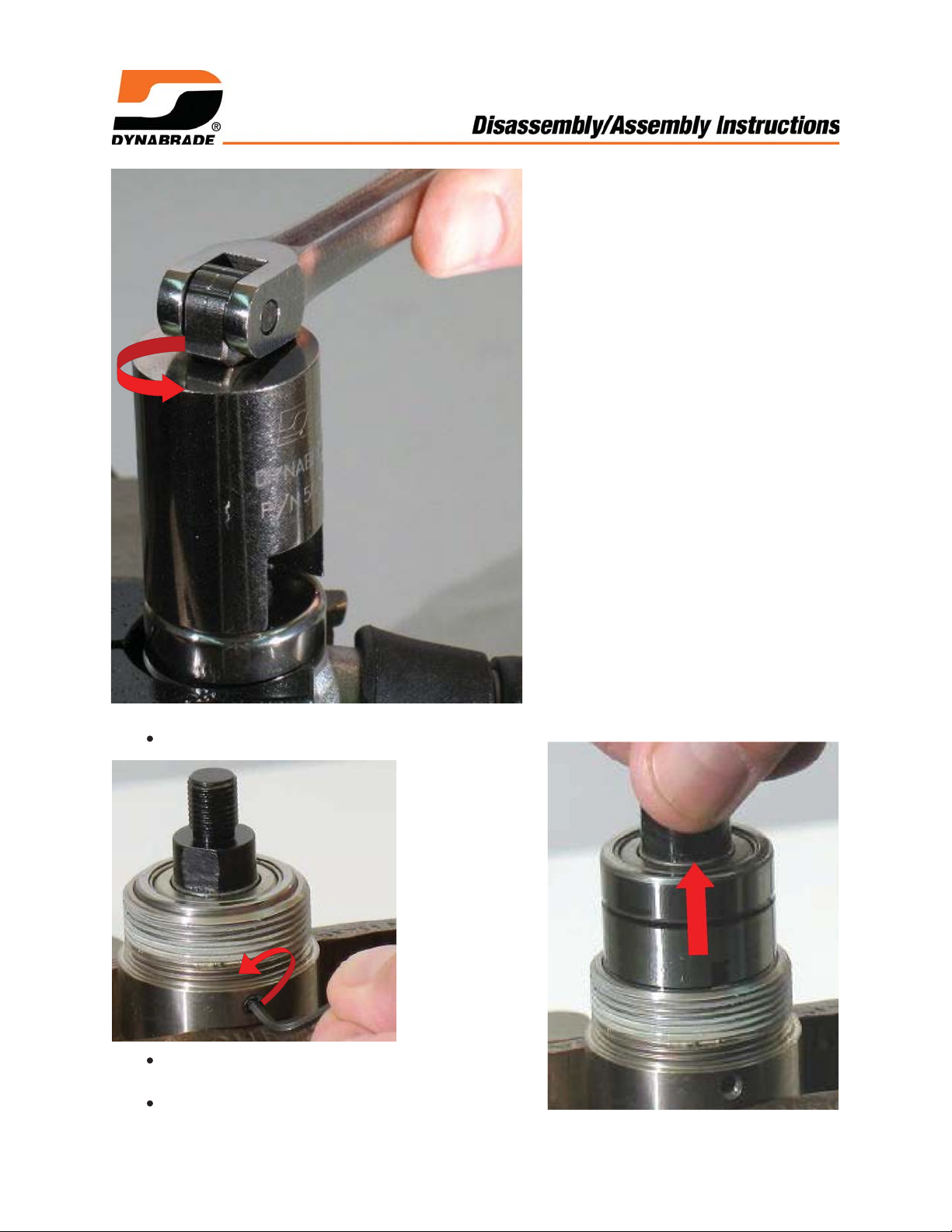
Use 3 mm hex key to loosen 95311 Screw and remove motor from belt housing.
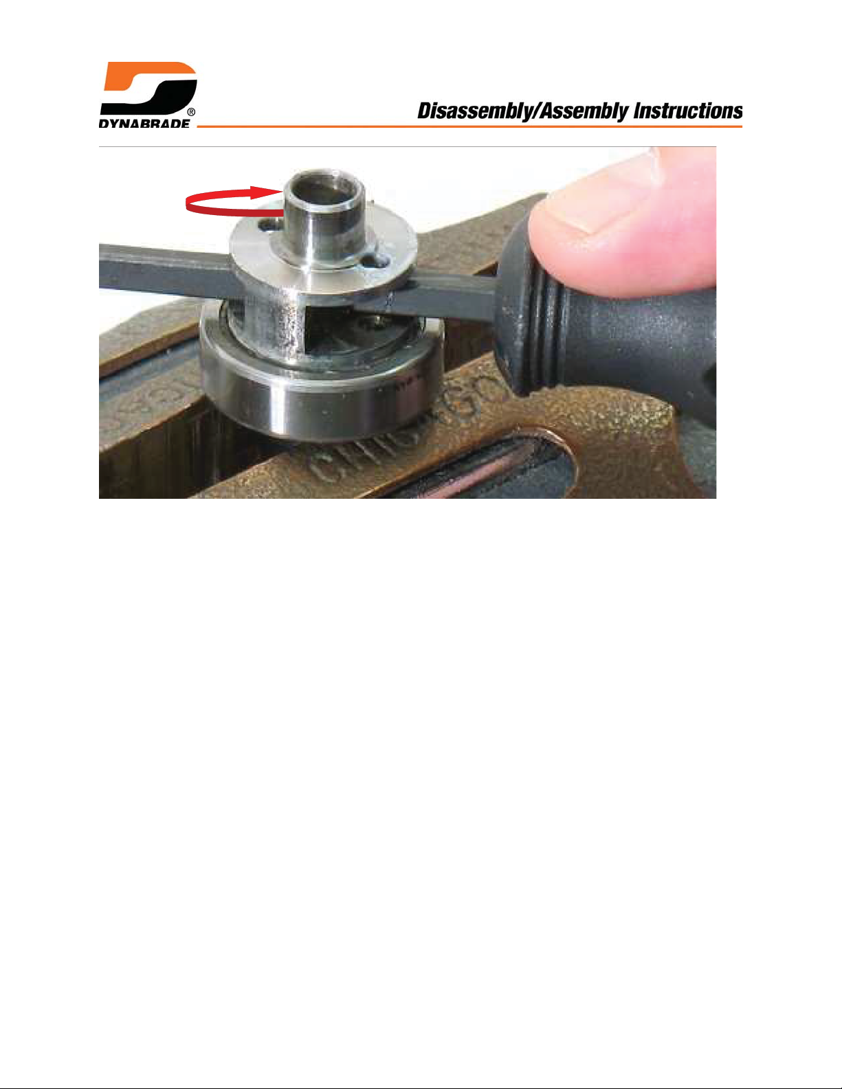
Use a small adjustable wrench to hold 40358 Adapter stationary. By hand remove
40375 Drive Wheel. Turn counterclockwise.
Motor Disassembly:
Planetary Gear Disassembly:
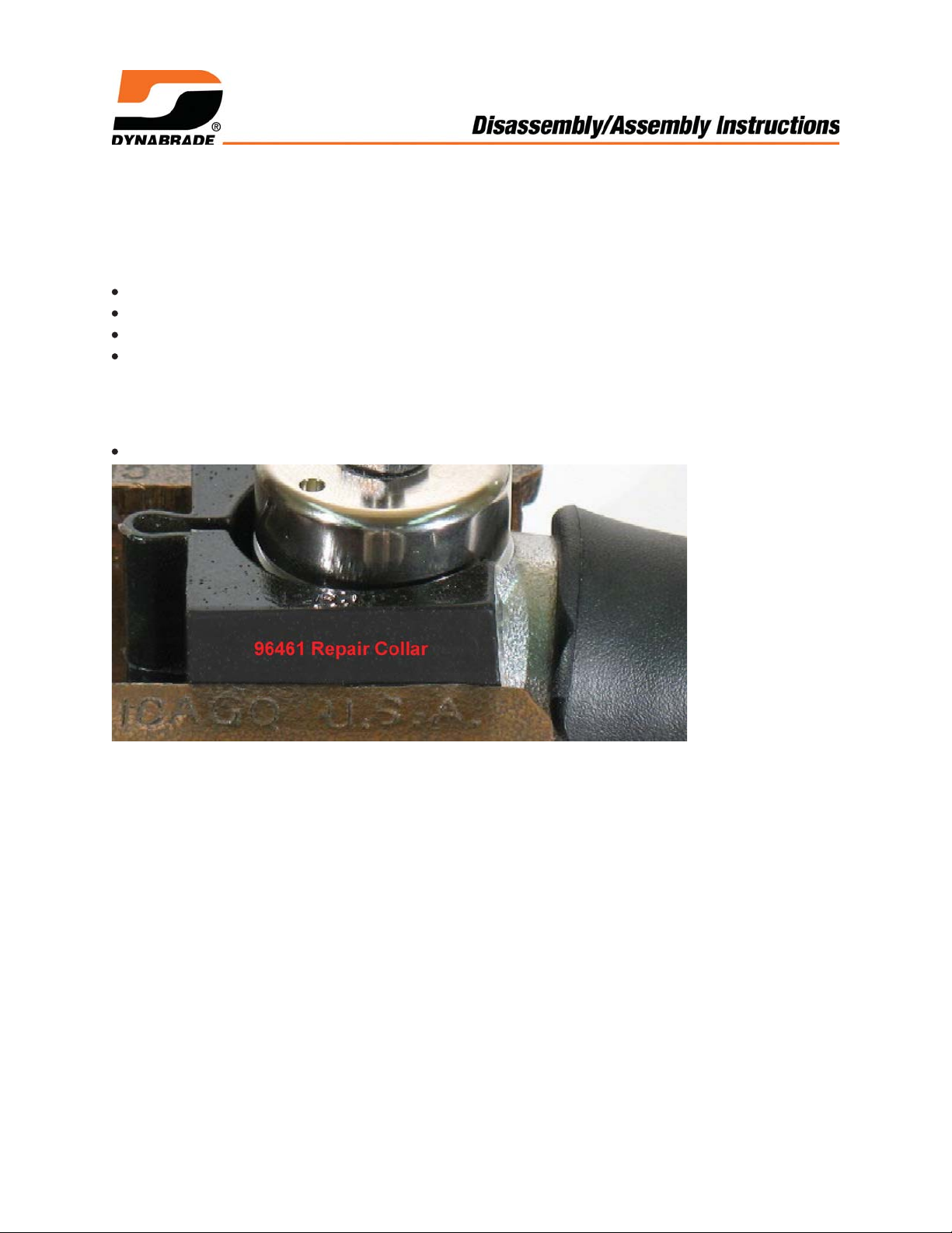
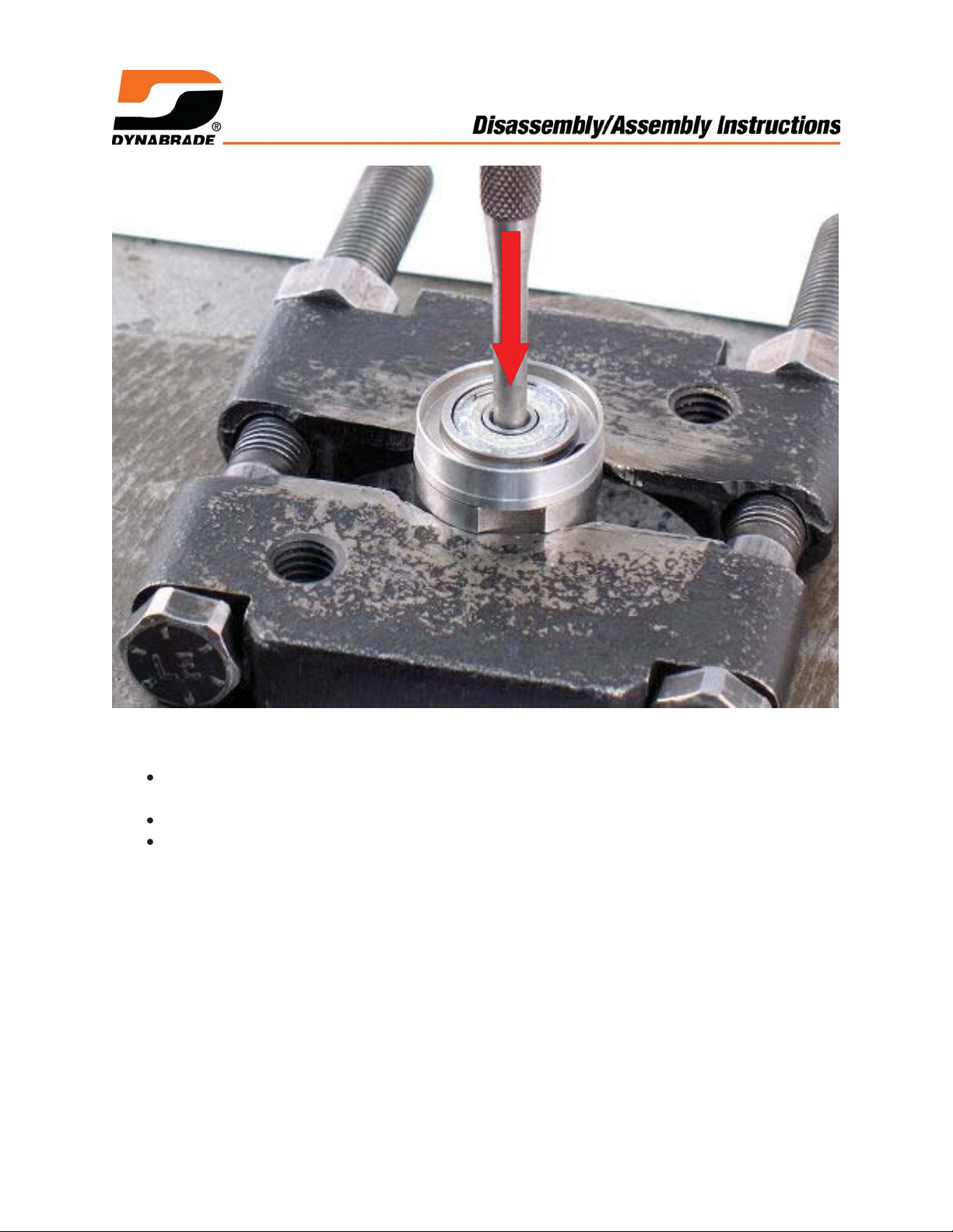
96461 Repair Collar
1. Use 96461 Repair Collar to hold housing in a vise with 40358 Adapter pointing up.
Page 2
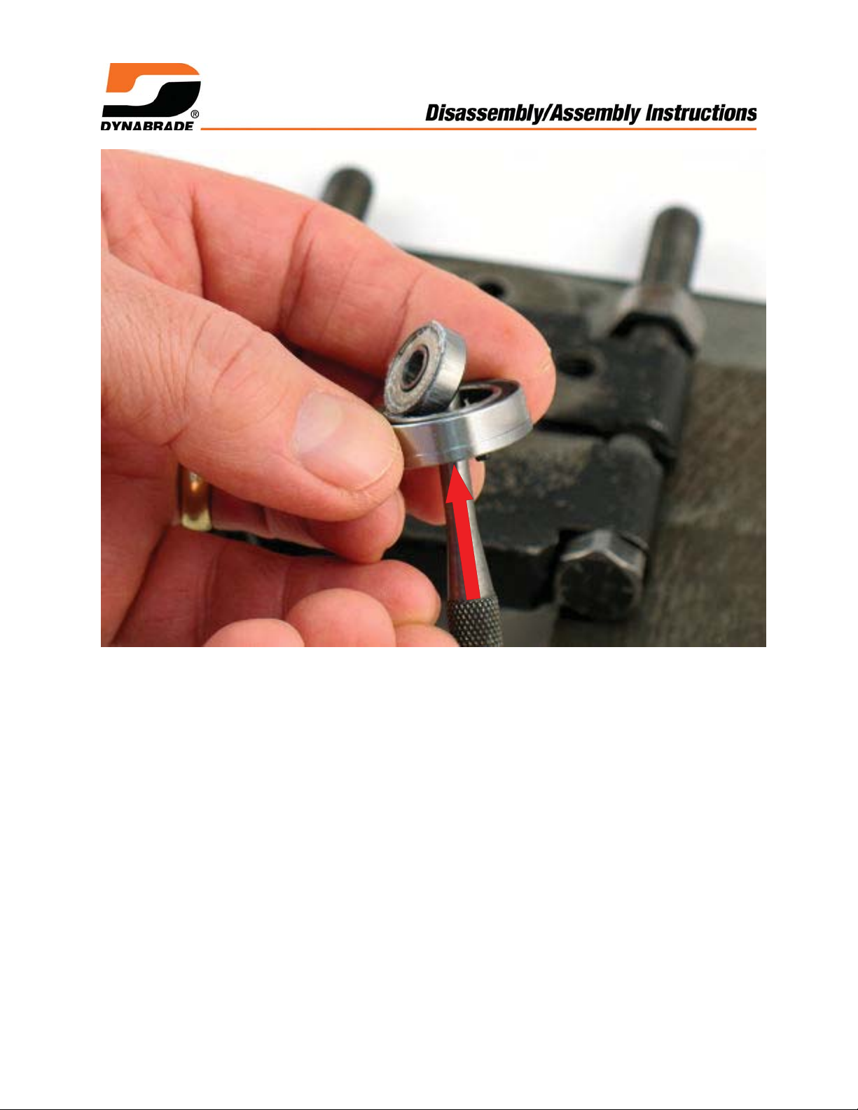
2. Use 50971 Lock Ring Tool to remove 40359 Exhaust Cover.
Turn counterclockwise.
Use a 2 mm hex key to remove 50784 Set
Screw.
Remove planetary gear assembly.
Page 3
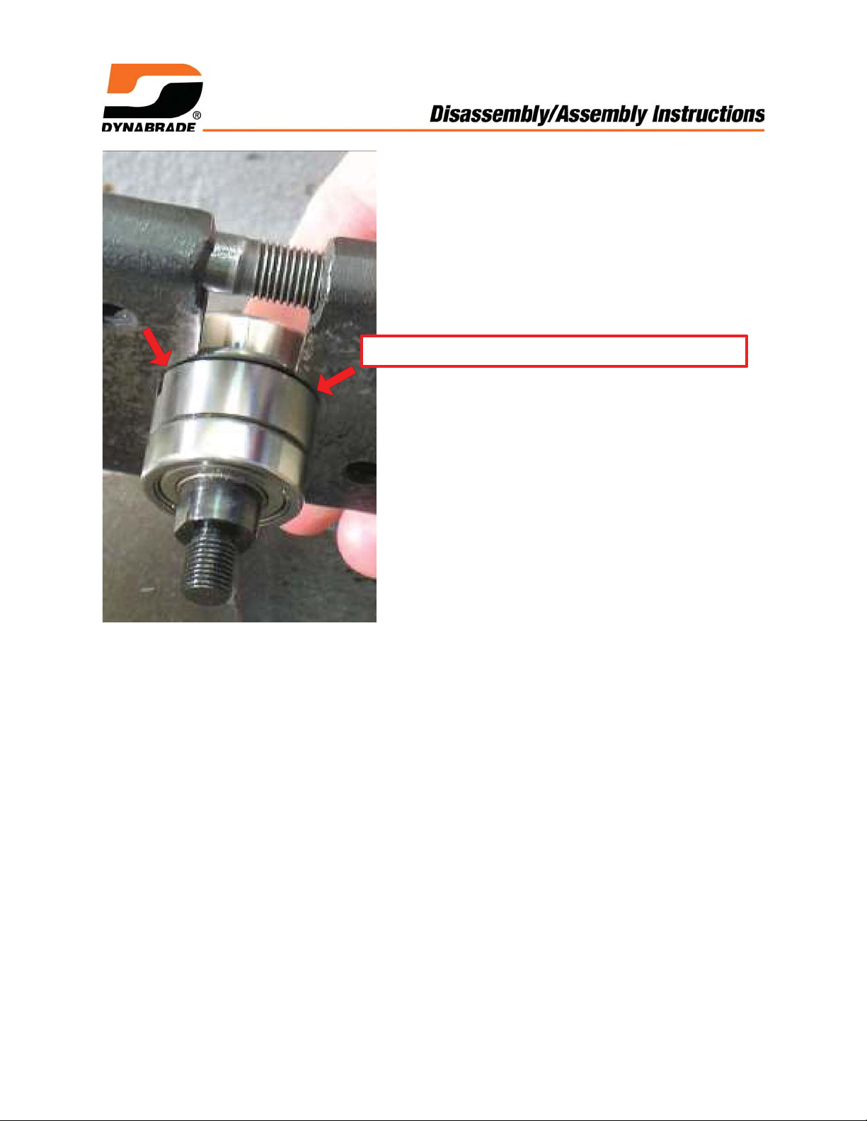
Flat side of 96346 Separator toward ring gear.
3. Fasten 96346 Bearing Separator between bearing and ring gear. Face flat side of
separator toward ring gear and bevel side toward bearing.
Page 4
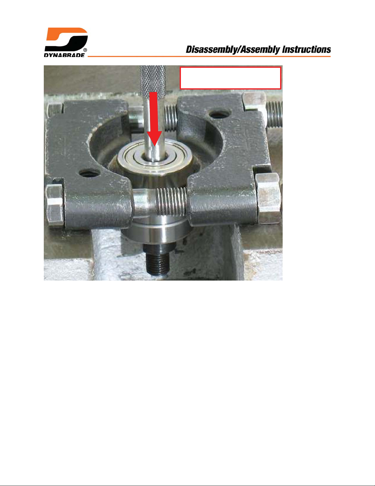
5/16" flat-end Drive Punch
and 96232 Arbor Press
4. Use a 5/16" flat-end drive punch as a press tool and 96232 Arbor Press to push the
planetary carrier out of the 54552 Bearing.
Page 5

5. Remove the ring gear.
To remove shafts and planet gears, gently tap the carrier on a hard surface.
The shafts and gears will fall out.
Page 6
6. With planetary carrier pointing up, carefully fasten 40358 Adapter in vise with
aluminum or bronze jaws.
Insert a screwdriver through carrier and turn counterclockwise to remove adapter.
Page 7
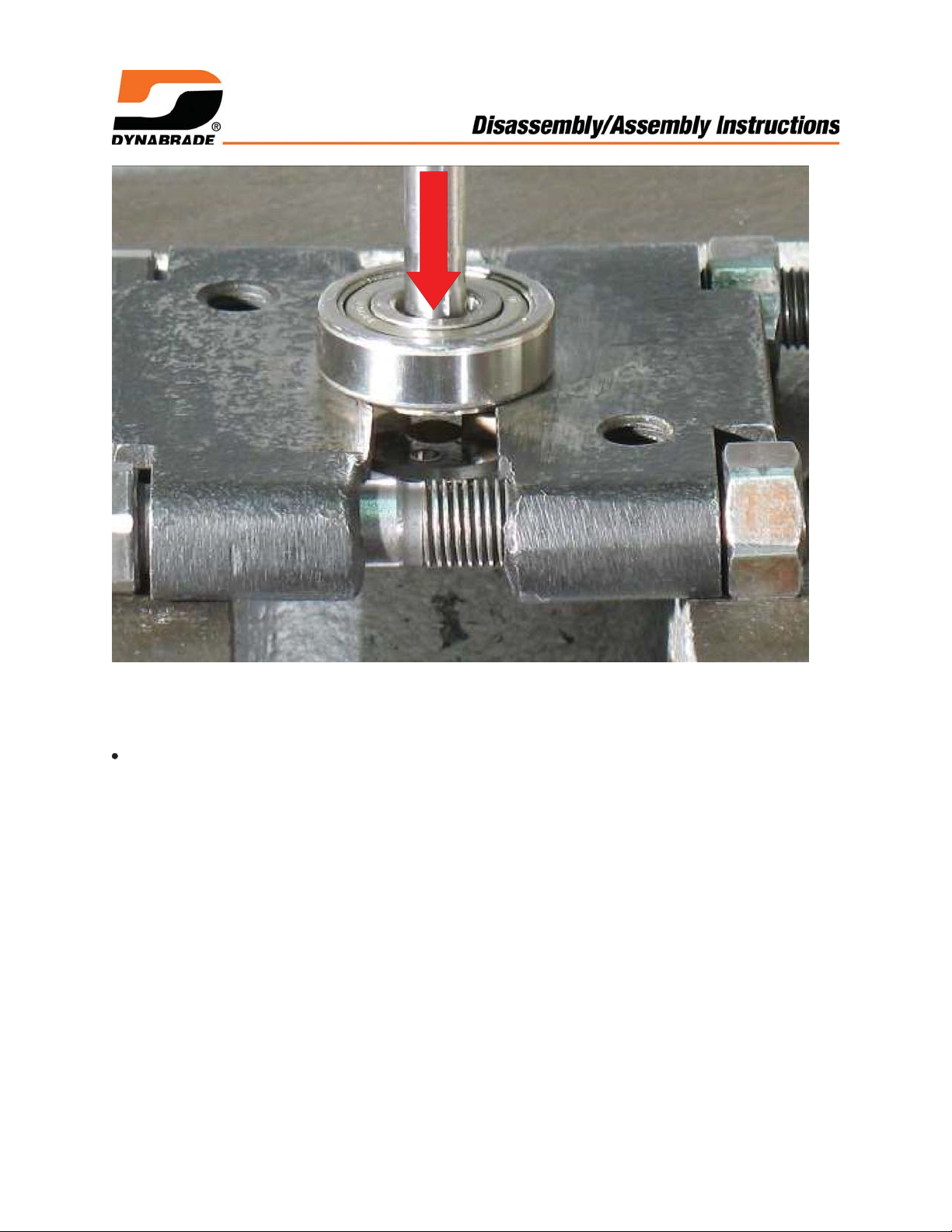
7. Use arbor press and 5/16" flat-end drive punch as a press tool to push the planetary
carrier out of the remaining 54552 Bearing.
Planetary gear disassembly completed.
Important: Clean and inspect parts before assembling.
Page 8
Motor Disassembly:
1. Pull motor from housing.
Page 9
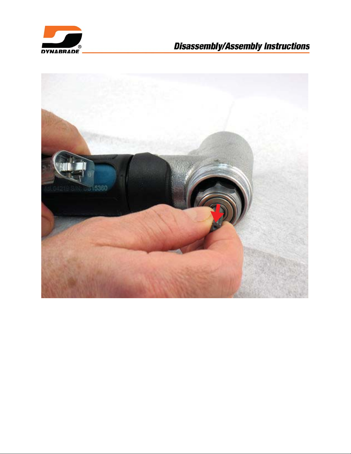
2. Remove 02679 Shield from 02696 Bearing.
Page 10
3. Fasten 96346 Bearing Separator (2") around 01476 Cylinder.
Place bearing separator and motor in 96232 Arbor Press (#2) with pinion
pointing down.
Use a Ø 3/16" or ~4 mm flat-end drive punch to push rotor out of bearing.
Remove cylinder and vanes.
Page 11
4. By hand, use Ø 3/16" or ~4 mm flat-end drive punch to push 02696 Bearing (slip-fit)
out of 02673 Rear Plate.
Page 12

5. With pinion gear pointing up, use arbor press to push rotor out of 02649 Bearing.
Page 13

6. Remove 02649 Bearing, front plate, shims and 01479 Spacer.
Motor disassembly completed.
Important: Clean and inspect parts before assembling.
Page 14

Assembly Instructions - 0.4 hp, Dynafile II Slow Speed
Motor Assembly:
02649 Bearing
01478 Front Plate
01479 Spacer
1. Install 01479 Spacer onto rotor.
Select .003" (~0.08 mm) shim thickness from 54529 Shim Pack.
Install shims into front plate.
Install 02649 Bearing into front plate.
54553 Rotor
Page 15

2. Use arbor press and RAISED INSIDE DIAMETER of the 96240 Bearing Press
Tool to install 02649 Bearing with bearing plate onto rotor.
Page 16

.001"-.0015"
(~0.03-0.04 mm)
3. By hand, move front plate forward away from rotor and check the amount of
clearance between rotor and front plate.
Use a .001" (~0.03 mm) thick feeler gauge. Notice: The clearance should be
.001"-.0015" (~0.03-0.04 mm). If rotor/plate clearance needs adjustment, repeat
steps 1 and 2. - Remove or add shims as required.
Page 17

Oil
4. Oil vanes with 95842 Dynabrade Air Lube 10W/NR or equivalent, and install.
Page 18

5. Install 01476 Cylinder and 02673 Rear Plate so that air inlet openings line-up.
Page 19

96242 Bearing Press Tool
Just Touch
6. Use RAISED INSIDE DIAMETER of 96242 Bearing Press Tool and arbor press to
install 02696 Bearing and rear plate.
Important: Press bearing and plate down until the rear plate just touches the
cylinder. This will produce a close fit between the bearing plates and cylinder.
Page 20

02679 Shield
AIR INLET
CLEAN GREASE
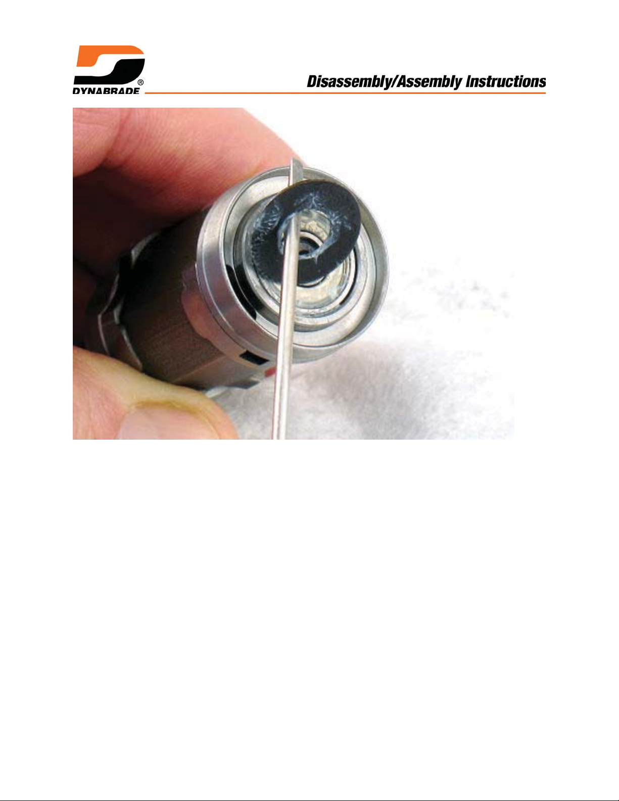
7. Apply a small amount of clean grease on shield of 02696 Bearing.
Stick 02679 Shield against bearing.
Notice: The 02673 Rear Plate channels the inlet air. It is not necessary to line-up
motor air inlet with housing air inlet.
Page 21

50778 SPACER
BEVELED SIDE UP
8. Install motor into housing.
Install 50778 Spacer with flat side toward motor and beveled side facing up.
Page 22

Planetary Gear Assembly:
THREAD AT FRONT OF CARRIER
PRESS RAM
1. Use the RAISED INSIDE DIAMETER of the 96239 Bearing Press Tool and the
arbor press to install the 54552 Bearing onto the front of the planetary carrier.
Page 23

Loctite #271
2. Apply a small amount of Loctite #271 (or equivalent) to the adapter thread.
Page 24

T to 17 N•m/~150 lbs. in.
3. Carefully hold planetary carrier in vise with aluminum or bronze jaws and install the
adapter onto carrier. (T to 17 N•m/~150 lbs. in.)
Page 25

4. Apply 95542 Grease (or equivalent) to the needle bearings in the planet gears. Install
gears and 54472 Shafts into carrier.
Page 26

5. Install 54468 Ring Gear so that openings line-up with the lubricant and set screw
holes in housing.
Page 27

PRESS RAM
96239 BEARING
PRESS TOOL
JUST TOUCH
6. Use RAISED INSIDE DIAMETER of 96239 Bearing Press Tool and the arbor
press to install 54552 Bearing onto planetary carrier.
IMPORTANT: Carefully press bearing to just touch the ring gear. This will
produce a close fit between the bearings and ring gear.
Page 28

Loctite #567
7. Install planetary gear assembly into housing.
Apply Loctite #567 (or equivalent) to the 50784 Set Screw and install.
Planetary gear assembly completed.
Page 29

Loctite #567
8. Apply a small amount of Loctite #567 to threads of housing.
Page 30

Torque to 34 N•m/~300 lbs. in.
9.
Use 50971 Lock Ring Tool and torque wrench to fasten exhaust cover.
(Torque to 34 N•m/~300 lbs. in.)
Motor assembly completed.
Final Assembly:
See: Disassembly and Assembly for Rear Exhaust, 7° Off-Set Throttle Body.
Notice: To disassemble and assemble valve components, muffler, and belt housing
assembly, see exploded view found in tool manual.
1. Important: Without an accessory installed, check spindle speed of tool with max.
90 PSIG or 6.2 Bar operating air pressure at air inlet of tool.
Use a tachometer to check RPM. Notice: Unless otherwise stated, the no-load
speed should not exceed the maximum rated speed.
Install drive wheel and, install motor into belt housing.
Final assembly completed.
Page 31

Disassembly Instructions - Throttle Body, Valve and Muffler - 7° Off-Set
1. Use 96461 Repair Collar to fasten 7° Off-Set Housing in a vise with with motor
spindle pointing down.
2. Pull 01558 Collar back onto throttle body housing.
Use 96460 Wrench to loosen throttle body lock nut from 7° Off-Set Housing.
Turn clockwise. Left Hand Thread
Page 32

3. Fasten 94523 Inlet Adapter in a vise with aluminum or bronze jaws, with throttle
body pointing up.
Use 96393 Throttle Body Socket to remove throttle body from muffler assembly.
Turn counterclockwise.
4. To disassemble muffler and valve components, see exploded view in tool manual.
Throttle Body, valve and muffler disassembly completed.
Assembly Instructions - Throttle Body, Valve and Muffler - 7° Off-Set
1. To assemble valve and muffler components, see exploded view in tool manual.
2. Install air control ring onto 94523 Inlet Adapter.
Apply a small amount of Loctite #567 to male thread of inlet adapter.
By hand, install muffler assembly onto the throttle body.
Page 33

T to 28 N•m/~250 in. lbs.
3. Fasten 94523 Inlet Adapter vise with throttle body pointing up.
Use 96393 Throttle Body Socket and torque wrench to throttle body onto muffler
assembly. Turn clockwise. (Torque to 28 N•m/~250 in. lbs.)
Apply Clean Grease
4. Apply a small amount of clean grease to 95523 O-Ring and install it onto the throttle
body.
Page 34

Loctite #567
5. Apply Loctite Primer #7649 to threads of 7° Off-Set housing.
Apply a small amount of Loctite #567 to threads.
T to 45 N•m/~400 in. Lbs.
6. Install throttle body onto .
Notice: Hold throttle lever in the desired position. Use 96460 Wrench and a
torque wrench to fasten throttle body assembly onto the 7° Off-Set housing.
Turn counterclockwise. Left Hand Thread (Torque to 45 N•m/~400 in. Lbs.)
Throttle Body, valve and muffler assembly completed.
 Loading...