


Mini-Dynafile® II
Parts Page Reorder No. PD06•19
Effective July, 2006
Supersedes PD05•32
For Serial No. 6B1660 and Higher
Air Tool Manual – Safety, Operation and Maintenance
SAVE THIS DOCUMENT, EDUCATE ALL PERSONNEL
Models:
15003 – Basic Tool
 WARNING
Read and understand this tool manual before operating your air tool. Follow all safety rules for the protection of operating personnel as well as adjacent areas. Always operate, inspect and maintain this tool in accordance with the American National Safety Institute (ANSI) Safety Code for Portable Air Tools – B186.1. For additional safety information, refer to Safety Requirements for the Use, Care and Protection of Abrasive Wheels – ANSI B7.1, Code of Federal Regulation – CFR 29 Part 1910, European Committee for Standards (EN) Hand Held Non-Electric Power Tools – Safety Requirements and applicable State and Local Regulations.
SAFETY LEGEND
|
|
|
WARNING |
|
|
|
WARNING |
|
|
|
Read and understand tool manual before |
|
Practice safety requirements. Work alert, |
||||
|
|
work starts to reduce risk of injury to |
|
have proper attire, and do not operate tools under |
||||
|
|
operator, visitors, and tool. |
|
the influence of alcohol or drugs. |
||||
 WARNING
Eye protection must be worn at all times, eye protection to conform to ANSI Z87.1.
 WARNING
Ear protection to be worn when exposure to sound, exceeds the limits of applicable Federal, State or local statues, ordinances and/or regulations.
|
WARNING |
|
|
|
WARNING |
|
Respiratory protection to be used when exposed to contaminants that exceed the applicable threshold limit values required by law.
Air line hazard, pressurized supply lines and flexible hoses can cause serious injury. Do not use damaged, frayed or deteriorated air hoses and fittings.
 WARNING
Some dust created by sanding, grinding, drilling, and other construction activities contain chemicals known to cause cancer, birth defects or other reproductive harm. Some examples of these chemicals are:
•Lead from lead-based paints
•Crystalline silica from bricks and cement and other masonry products
•Arsenic and chromium from chemically treated lumber
Your risk from these exposures varies, depending on how often you do this type of work. To reduce your exposure to these chemicals: work in a well ventilated area, and work with approved safety equipment, such as those dust masks that are specially designed to filter out microscopic particles.
SAFETY INSTRUCTIONS
Carefully Read all instructions before operating or servicing any Dynabrade® Abrasive Power Tool.
Products offered by Dynabrade are not to be modified, converted or otherwise alerted from the original design without expressed written consent from Dynabrade, Inc.
Tool Intent: Dynafile® abrasive belt machine replaces tedious hand filing and sanding and can be used for grinding, deburring, blending and polishing. Tool can be used on most materials including metal, plastic, fiberglass, composites, rubber, glass and stone.
Do not use tool for anything other than its intended applications.
This power tool is not intended for use in potentially explosive atmospheres and is not insulated against contact with electrical power.
Training: Proper care, maintenance, and storage of your tool will maximize its performance.
• Employer's Responsibility – Provide Dynafile® operators with safety instructions and training for safe use of tools and accessories.
Accessory Selection:
•Abrasive/accessory RPM (speed) rating MUST be approved for AT LEAST the tool RPM rating.
•Before mounting an accessory, visually inspect for defects. Do not use defective accessories.
•Mount only recommended accessories. See manual and Dynabrade catalog.
•Follow tool specifications before choosing size and type of accessory.
•Only use recommended fittings and air line sizes. (See tool Machine Specifications table.)
(continued on next page)
OPERATING INSTRUCTIONS
Warning: Always wear eye protection. Operator of tool is responsible for following: accepted eye, face, respiratory, hearing and body protection. Caution: Hand, wrist and arm injury may result from repetitive work, motion and overexposure to vibration.
•Only use recommended fittings and air line sizes. Air supply hoses and air hose assemblies must have a minimum working pressure rating of 150 PSIG (10 Bars, g) or 150 percent of the maximum pressure produced in the system, whichever is higher. (See tool Machine Specifications table.)
•Keep hand and clothing away from working end of the air tool.
•Be sure that any loose clothing, hair and all jewelry is properly restrained.
•Secure inlet bushing on air tool with a wrench before attempting to install the air fitting to avoid damaging housing assembly.
•Check tool RPM (speed) with tachometer with air pressure set at 90 PSIG while the tool is running. If tool is operating at a higher speed than the RPM marked on the tool housing, or operating improperly, the tool must be serviced and corrected before use.
Caution: Tool RPM must never exceed abrasive/accessory RPM rating. Check accessory manufacturer for details on maximum operating speed or special mounting instructions.
•Disconnect air hose from tool when changing belts and contact arms.
•Connect air tool to power source. Be careful NOT to depress throttle lever in the process. Do not expose air tool to inlet pressure above 90 PSIG or (6.2 Bars). Caution: After installing the accessory, before testing or use and/or after assembling tool, the Dynafile® must be started at a reduced speed to check for good balance.
Gradually increase tool speed. DO NOT USE if tool vibration is excessive. Correct cause, and retest to insure safe operation.
•Make sure that work area is uncluttered, and visitors are at a safe range from the tools and debris.
•Use a vise or clamping device to hold work piece firmly in place.
•Do not apply excessive force on tool or apply “rough” treatment to it.
•Always work with a firm footing, good posture and proper lighting.
•Make sure that work area is uncluttered, and visitors are at a safe range from the tools and debris. Potentially explosive atmospheres can be caused by dust and fumes resulting from sanding or grinding. Always use dust extraction or suppression systems which are suitable for the material being processed.
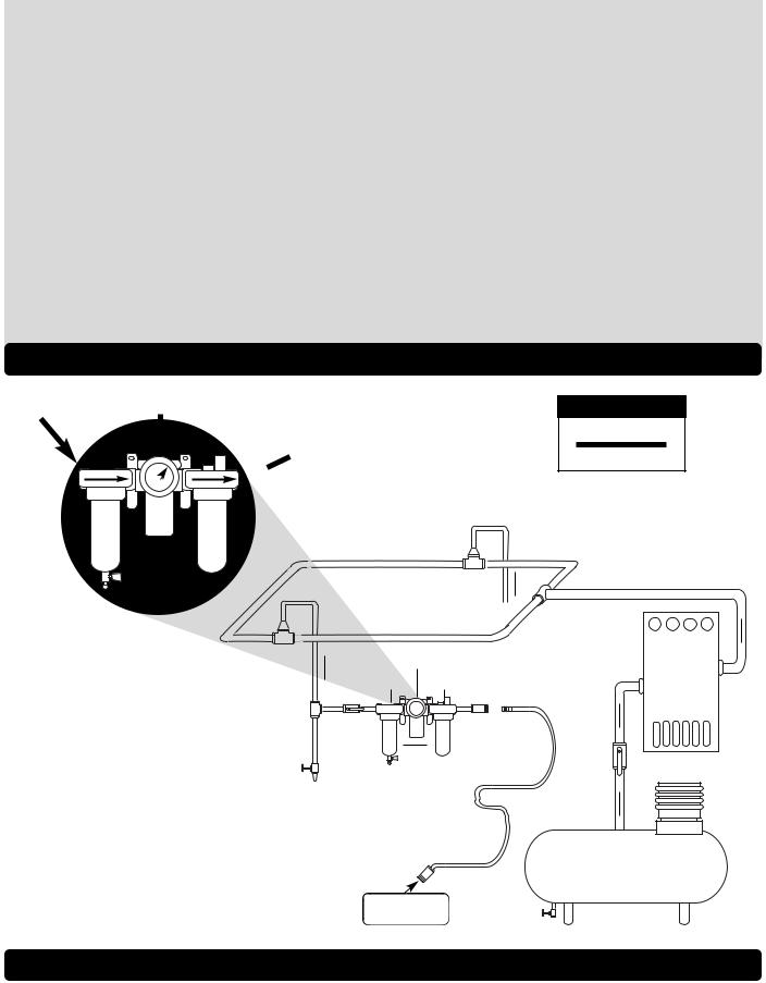
Air System
Filter Regulator
 Lubricator
LUBRICATOR SETTING
1DROP/MIN.
10 SCFM
90 PSIG
(6.2 Bar)
Closed Loop Pipe System |
Air Flow |
|
|
||
|
Machine Specifications
Model |
Motor |
Motor |
Max. SFPM |
Sound |
Air Flow Rate |
Abrasive Belt Size |
Weight |
Length |
Height |
Number |
HP (W) |
RPM |
(SMPM) |
Level |
CFM/SCFM (LPM) |
Inch (mm) |
Pound (kg) |
Inch (mm) |
Inch (mm) |
All Models |
.4 (298) |
25,000 |
4,890 (1,486) |
78 dB(A) |
3/20 (566) |
1/8"-1/2" (3-13)W x 12" (305)L |
1.8 (.82) |
10-3/4 (275) |
3-1/2 (89) |
|
|
|
|
|
|
|
|
|
|
Additional Specifications: Air Inlet Thread 1/4" NPT • Hose I.D. Size 1/4" or 8mm • 90 PSIG (6.2 Bars)
2

Maintenance Instructions
Important: A Preventative Maintenance Program is recommended whenever portable power tools are used.
•Use only genuine Dynabrade replacement parts to insure quality. To order replacement parts, specify Model #, Serial # and RPM of your air tool.
•It is strongly recommended that all Dynabrade rotary vane air tools be used with a Filter-Regulator-Lubricator to minimize the possibility of misuse due to unclean air, wet air or insufficient lubrication. Dynabrade recommends the following: 11405 Air Filter-Regulator-Lubricator (FRL) – Provides for air pressure regulation, two stage filtration of water and contaminants. Operates 40 SCFM/1,133 LPM @ 100 PSIG with 3/8" NPT female ports.
•Dynabrade recommends one drop of air lube per minute for every 10 SCFM (example: if the tool specification states 40 SCFM, set the drip rate on the filter-lubricator to 4 drops per minute). Dynabrade Air Lube (P/N 95842: 1 pt 473 ml) is recommended.
Routine Preventative Maintenance: Check free speed of Dynafile® using a tachometer.
•Mineral spirits are recommended when cleaning the tool and parts. Do not clean tool or parts with any solvents or oils containing acids, esters, ketones, chlorinated hydrocarbons or nitro carbons.
•DO NOT clean or maintain tools with chemicals that have a low flash point (example: WD-40®).
•A Motor Tune-Up Kit (P/N 96074) is available which includes high wear and medium wear motor parts.
•Air tool labels must be kept legible at all times, if not, reorder label(s) and replace. User is responsible for maintaining specification information i.e.: Model #, S/N, and RPM. (See Assembly Breakdown)
•Blow air supply hose out prior to initial use.
•Visually inspect air hoses and fittings for frays, visible damage and signs of deterioration. Replace damaged or worn components.
•Refer to Dynabrade's Warning/Safety Operating Instructions Tag (Reorder No. 95903) for safety information.
After maintenance is performed on tool, add a few drops of Dynabrade Air Lube (P/N 95842) to the air line and start the tool a few times to lubricate air motor. Check for excessive tool vibration.
Handling and Storage:
•Use of tool rests, hangers and/or balancers is recommended.
•Protect tool inlet from debris (see Notice below).
•DO NOT carry tool by air hose.
•Protect abrasive accessories from exposure to water, solvents, high humidity, freezing temperature and extreme temperature changes.
•Store accessories in protective racks or compartments to prevent damage.
Notice
All Dynabrade motors use the highest quality parts and metals available and are machined to exacting tolerances. The failure of quality pneumatic motors can most often be traced to an unclean air supply or the lack of lubrication. Air pressure easily forces dirt or water contained in the air supply into motor bearings causing early failure. It often scores the cylinder walls and the rotor blades resulting in limited efficiency and power. Our warranty obligation is contingent upon proper use of our tools and cannot apply to equipment which has been subjected to misuse such as unclean air, wet air or a lack of lubrication during the use of this tool.
One Year Warranty
Following the reasonable assumption that any inherent defect which might prevail in a product will become apparent to the user within one year from the date of purchase, all equipment of our manufacture is warranted against defects in workmanship and materials under normal use and service. We shall repair or replace at our factory, any equipment or part thereof which shall, within one year after delivery to the original purchaser, indicate upon our examination to have been defective. Our obligation is contingent upon proper use of Dynabrade tools in accordance with factory recommendations, instructions and safety practices. It shall not apply to equipment which has been subject to misuse, negligence, accident or tampering in any way so as to affect its normal performance. Normally wearable parts such as bearings, contact wheels, rotor blades, etc., are not covered under this warranty.
Abrasive Belt and Contact Arm Assembly Change / Housing Angle Adjustment
To Change Abrasive Belts:
1.Disconnect the tool from the power source.
2.Loosen the 15119 Captive Screw and remove the 15103 Guard Assembly.
3.Pull back the 15101 Tension Arm and remove the abrasive belt.
4.Install a new abrasive belt, and the 15103 Guard Assembly.
5.Connect the tool to the power source and adjust the belt tracking by turning the 15108 Knob.
To Change Contact Arm Assemblies:
1.Disconnect the tool from the power source.
2.Loosen the 15119 Captive Screw and remove the 15103 Guard Assembly.
3.Pull back the 15101 Tension Arm and remove the abrasive belt.
4.Loosen the 15108 Knob to remove the contact arm assembly.
5.Install the desired contact arm assembly so that the tab on the end of the arm faces toward the 15101 Tension Arm.
6.Fasten the contact arm assembly in place with the 15108 Knob.
7.Install a new abrasive belt, and the 15103 Guard Assembly.
8.Connect the tool to the power source and adjust the belt tracking by turning the 15108 Knob.
Housing Angle Adjustment:
1.To pivot the 15115 Housing Assembly, use a 3mm hex key to loosen the 01788 Motor Lock Screw.
2.Pivot the housing assembly and fasten it to the desired position.
3
 Loading...