

Page 1
SAFETY INSTRUCTIONS
Carefully Read all instructions before operating or servicing any Dynabrade
®
Abrasive Power Tool. Products offered by Dynabrade are not to be modified, converted
or otherwise altered from the original design without expressed written consent from Dynabrade, Inc.
Tool Intent: 5" Random Orbital Buffers are ideal for buffing and polishing.
Do not use tool for anything other than intended applications.
This power tool is not insulated against contact with electrical power source.
Training: Proper care, maintenance, and storage of your tool will maximize their performance.
• Employer's Responsibility – Provide 5" Random Orbital Buffer operators with safety instructions and training for safe use of tools and accessories.
Accessory Selection:
• Abrasive/accessory RPM (speed) rating MUST be approved for AT LEAST the tool RPM rating.
• Before mounting an accessory, visually inspect for defects. Do not use defective accessories.
• Use only recommended accessories. See back page of manual and Dynabrade catalog.
• Follow tool specifications before choosing size and type of accessory.
• Only use recommended fittings and air line sizes. Air supply hoses and air hose assemblies must have a minimum working pressure rating of 150 PSIG (10 Bars, g) or 150
percent of the maximum pressure produced in the system, whichever is higher. (See tool Machine Specifications table.)
OPERATING INSTRUCTIONS
Warning: Always wear eye protection. Operator of tool is responsible for following: accepted eye, face, respiratory, hearing and body protection.
Caution: Hand, wrist and arm injury may result from repetitive work, motion and overexposure to vibration.
• Keep hand and clothing away from working end of the air tool. Be sure that any loose clothing, hair and all jewelry is properly restrained.
(continued on next page)
Parts Page Reorder No. APD08•03
Effective July, 2008
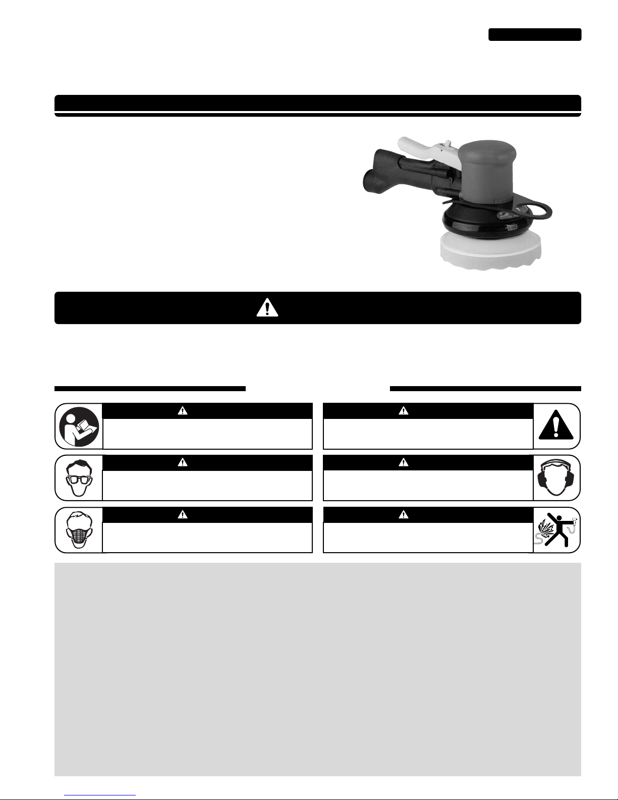
5" Random Orbital Buffer
Air Tool Manual – Safety, Operation and Maintenance
Model:
10746 – 10,000 RPM
– Non-Vac
– Front Exhaust
– w/Hanger
SAFETY LEGEND
G
Read and understand tool manual before
work starts to reduce risk of injury to
operator, visitors, and tool.
Eye protection must be worn at all times,
eye protection to conform to ANSI Z87.1.
Respiratory protection to be used when exposed to
contaminants that exceed the applicable threshold
limit values required by law.
Practice safety requirements. Work alert,
have proper attire, and do not operate tools under
the influence of alcohol or drugs.
Ear protection to be worn when exposure to sound,
exceeds the limits of applicable Federal, State or
local statues, ordinances and/or regulations.
Air line hazard, pressurized supply lines and flexible
hoses can cause serious injury. Do not use damaged,
frayed or deteriorated air hoses and fittings.
Read and understand this tool manual before operating your air tool. Follow all safety rules for the protection of operating personnel
as well as adjacent areas. Always operate, inspect and maintain this tool in accordance with the American National Safety Institute
(ANSI) Safety Code for Portable Air Tools – B186.1. For additional safety information, refer to Code of Federal Regulation – CFR 29
Part 1910, European Committee for Standards (EN) Hand Held Non-Electric Power Tools – Safety Requirements and applicable State
and Local Regulations.
SAVE THIS DOCUMENT, EDUCATE ALL PERSONNEL
AUTOMOTIVE
WARNIN
WARNING
WARNING
WARNING
WARNING
WARNING
WARNING
Page 2
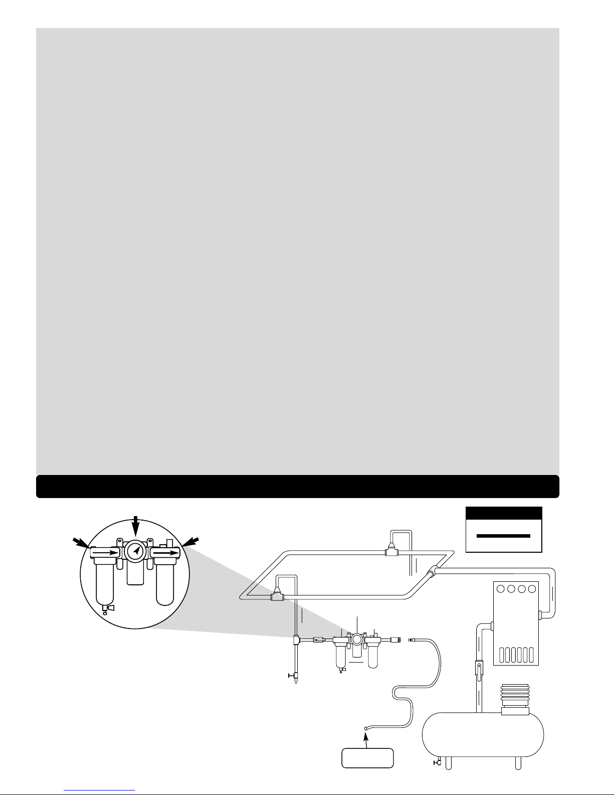
Filter
Regulator
Lubricator
90 PSIG
(6.2 Bar)
To Tool Station
Closed Loop Pipe System
(Sloped in the direction of air flow)
Ball
Valve
Ball
Valve
Filter
Regulator
Lubricator
Air Flow
Drain
Valve
Drain
Valve
Air Tool
Air Compressor
and Receiver
Drain
Valve
Air Hose
90 PSIG MAX
(6.2 Bar)
Air Flow
Refrigerated
Air Dryer
2
OPERATING INSTRUCTIONS (continued)
• Secure inlet bushing on air tool with a wrench before attempting to install the air fitting to avoid damaging housing assembly.
• BEFORE MOUNTING AN ACCESSORY, after all tool repairs and whenever a 5" Random Orbital Buffer is issued for use, check tool RPM (speed) with tachometer with air
pressure set at 90 PSIG while the tool is running. If tool is operating at a higher speed than the RPM marked on the tool housing, or operating improperly, the tool must be
serviced and corrected before use.
• Caution: Tool RPM must never exceed abrasive/accessory RPM rating. Check accessory manufacturer for details on maximum operating speed or special
mounting instructions.
• With power source connected at the air tool relieve hose of air pressure and disconnect tool from air supply when changing recommended accessories.
• Connect air tool to power source. Be careful NOT to depress throttle lever in the process.
• Do not expose air tool to inlet pressure above 90 PSIG or (6.2 Bars).
• Caution:After installing the accessory, before testing or use and/or after reassembling tool, the 5" Random Orbital Buffer must be started at a reduced speed to check for
good balance. Gradually increase tool speed. DO NOT USE if tool vibration is excessive. Correct cause, and retest to insure safe operation.
• Use only coated abrasive sanding discs or sheets properly secured to the backing pad provided with the air sander. Ensure that self-fixing sanding discs
are mounted concentrically.
• Make sure that work area is uncluttered, and visitors are at a safe range from the tools and debris. Potentially explosive atmospheres can be caused
by dust and fumes resulting from sanding or grinding. Always use dust extraction or suppression systems which are suitable for the
material being processed.
• Proceed with caution in unfamiliar surroundings. Hidden hazards may exist, such as electricity or other utility lines.
• Air tools are not intended for use in explosive atmospheres and are not insulated for contact with electric power sources.
• Use a vise or clamping device to hold work piece firmly in place.
• Caution:This tool is not to be run at free speed for any length of time. The tool is specifically designed to be low in vibration under load. Running the tool at free speed may
cause the buffing pad to become dislodged from the back-up pad.
• All initial set-up and maintenance to the tool should be done with the air line disconnected from the tool.
• Install air fitting into inlet bushing of tool. The inlet bushing is a 1/4" NPT, for optimal performance of the tool. Either directly couple the air line to the tool or use a quick
couple fitting with a large inlet hole such as Dynabrade’s P/N 95675. Important: Secure inlet bushing of tool with a wrench before attempting to install the air fitting to avoid
damaging valve body housing.
• While there may be other applications suited for this tool it has been specifically designed for the automotive market to be used as the second step of a special two step
operation to remove paint imperfections in the clear coat of automotive finishes. The correct back-up pad and buffing pad are required to correctly operate the tool. Attach a
back-up pad to the tool that is compatible with the paint system. A variety of 3M 5" Hook-It pads with a 5/16"-24 male stud have been successful as well as Dynabrade pads,
for best results contact a Dynabrade or 3M representative.
• A waffle pad such as 3M P/N 01912 is required to be attached to the back-up pad. Pre-condition a virgin pad thoroughly with 3M Final Finish Finesse-It Compound 3M P/N
82876 before attaching it to the tool. Once the pad has been conditioned this process need not be done until a new waffle pad is required either due to wear or the com
pound has been allowed to set up rendering the pad useless.
• Apply a small (15mm) dab of Final Finish on the repaired area, and position tool on the repair surface. Apply approximately a 10 pound load on the pad before throttling the
tool on. Adjust the force on the pad as required to feel the “sweet spot” (low vibration). Buff 10-12 seconds flat followed by 2-3 seconds with the tool tipped up on an angle.
Release the throttle lever and then remove the tool from the work piece.
• Installing a new waffle pad can be safely accomplished when the tool is connected to the air line if when holding the tool upside down the operator places their fingers
between the housing and the lever. Holding the tool in this manner eliminates any possibility of the tool turning on during the pad changing operation. It is recommended to
practice this grip with the air line disconnected from the tool to become comfortable with the procedure before performing operation with the air line connected.
• When carrying the tool which is still connected to the air line the operator should insert their thumb between the handle and lever to eliminate possibility of activating the tool.
• Work may generate hazardous dust.
• Do not apply excessive force on tool or apply “rough” treatment to it.
• Always work with a firm footing, posture and proper lighting.
• Ensure that debris resulting from work do not create a hazard.
• This tool is rear exhaust. Exhaust may contain lubricants, vane material, bearing grease, and other materials flushed thru the tool.
Report to your supervisor any condition of the tool, accessories, or operation you consider unsafe.
Air System
1 DROP/MIN.
20 SCFM
LUBRICATOR SETTING
•
Dynabrade Air Power Tools are designed to
operate at 90 PSIG (6.2 Bar/620 kPa) maximum
air pressure at the tool inlet, when the tool is
running. Use recommended regulator to control
air pressure.
•
Ideally the air supply should be free from moisture.
To facilitate removing moisture from air supply,
the installation of a refrigerated air dryer after the
compressor and the use of drain valves at each
tool station is recommended.
➤
➤
➤
➤
➤
➤
Page 3

Maintenance Instructions
Important: A preventative maintenance program is recommended whenever portable power tools are used. The program should include inspection of air supply lines, air line
pressure, proper lubrication and repair of tools. Refer to ANSI B186.1 for additional maintenance information.
•
Use only genuine Dynabrade replacement parts to insure quality. To order replacement parts, specify Model#, Serial# and RPM of your air tool.
•
It is strongly recommended that all Dynabrade rotary vane air tools be used with a Filter-Regulator-Lubricator to minimize the possibility of misuse due to unclean air, wet
air or insufficient lubrication. Dynabrade recommends the following: 11405 Air Filter-Regulator-Lubricator (FRL) – Provides accurate air pressure regulation and two stage
filtration of water contaminants. Operates 40 SCFM @ 100 PSIG with 3/8" NPT female ports.
•
Dynabrade recommends one drop of air lube per minute for each 20 SCFM (example: if the tool specification states 40 SCFM, set the drip rate on the filter-lubricator to 2
drops per minute). Dynabrade Air Lube (P/N 95842: 1 pt 473 ml) is recommended.
Routine Preventative Maintenance:
•
Check tool speed regularly with a tachometer. A Magnetic Tachometer such as Dynabrade P/N 96368 is the simplest way to perform this operation. There are two test
conditions to assure that the tool is running properly, these conditions being free speed and under load. The free speed is a simple check to quickly determine if the tool is
out of specification. Checking under load requires additional test equipment but assures the proper operation of the tool. All speed testing must be done with 90 psig of air
at the inlet bushing, a Pressure Gage such as Dynabrade P/N 94315 is required. The tool should run between 9,000 RPM and 11,000 RPM free speed with 90 psig at the
tool inlet bushing. If the tool is running outside these speeds it should be serviced to correct the cause before use. The under load condition can be checked by outfitting
the tool with the proper back-up pad, waffle pad and buffing cream as outlined in the operating instructions. Apparatus is also required to monitor the load applied to the
work surface. Dynabrade offers a Load Cell P/N 80025 that allows the tool to be tested on a a bench. First zero out the scale by adjusting the knob on the side of the load
cell to read zero when the tool, back-up pad, and waffle are resting on the wear plate of the load cell while connected to the air line. Apply a 10 pound load to the load cell
and using the digital tachometer check the operating speed of the tool. The tool should be running 5,500 RPM minimum. If the tool is running outside this range it should be
serviced to correct the cause before use.
•
Mineral spirits are recommended when cleaning the tool and parts. Do not clean tool or parts with any solvents or oils containing acids, esters, ketones, chlorinated
hydrocarbons or nitro carbons.
•
DO NOT clean or maintain tools with chemicals that have a low flash point (example: WD-40
®
).
•
A Motor Tune-Up Kit (P/N 98220) is available which includes high wear and medium wear motor parts.
•
Air tool labels must be kept legible at all times, if not, reorder label(s) and replace. User is responsible for maintaining specification information i.e.: Model #, S/N, and RPM
(See Assembly Breakdown)
•
Blow air supply hose out prior to initial use.
•
Visually inspect air hoses and fittings for frays, visible damage and signs of deterioration. Replace damaged or worn components.
•
Refer to Dynabrade's Warning/Safety Operating Instructions Tag (Reorder No. 95903) for safety information.
After maintenance is performed on tool, add a few drops of Dynabrade Air Lube (P/N 95842) to the air line and start the tool a few times to lubricate air motor.
Check for excessive tool vibration.
Handling and Storage:
•
Follow the handling instructions outlined in the operating instructions when carrying the tool and when changing buff pads.
•
Use of tool rests, hangers and/or balancers is recommended.
•
Protect tool inlet from debris (see Notice below).
•
DO NOT carry tool by air hose, or near the tool throttle lever.
•
Protect abrasive accessories from exposure to water, solvents, high humidity, freezing temperature and extreme temperature changes.
•
Store accessories in protective racks or compartments to prevent damage.
•
Air tools are not intended for use in explosive atmospheres and are not insulated for contact with electrical power sources. It is the employers responsibility to notify the
user of acceptable dust levels. It is the users responsibility to make sure the work area is free of flammable materials.
•
Tool should not be running for extended periods of time free speed as it is not balanced for this condition. Avoid running the tool at free speed with a buffing pad installed
onto the back-up pad as it may dislodge from the tool.
•
Always disconnect the air line before changing the back-up pad or making machine adjustments.
•
Warning: Never run the tool without shroud properly adhered to tool.
Notice
All Dynabrade motors use the highest quality parts and materials available and are machined to exacting tolerances. The failure of quality pneumatic motors can most often be
traced to an unclean air supply or the lack of lubrication. Air pressure easily forces dirt or water contained in the air supply into motor bearings causing early failure. It often
scores the cylinder walls and the rotor blades resulting in limited efficiency and power. Our warranty obligation is contingent upon proper use of our tools and cannot apply to
equipment which has been subjected to misuse such as unclean air, wet air or a lack of lubrication during the use of this tool.
One Year Warranty
Following the reasonable assumption that any inherent defect which might prevail in a product will become apparent to the user within one year from the date of purchase, all
equipment of our manufacture is warranted against defects in workmanship and materials under normal use and service. We shall repair or replace at our factory, any
equipment or part thereof which shall, within one year after delivery to the original purchaser, indicate upon our examination to have been defective. Our obligation is contingent
upon proper use of Dynabrade tools in accordance with factory recommendations, instructions and safety practices. It shall not apply to equipment which has been subject to
misuse, negligence, accident or tampering in any way so as to affect its normal performance. Normally wearable parts such as bearings, contact wheels, rotor blades, etc., are
not covered under this warranty.
Machine Specifications
3
Model Motor Motor Pad Dia. Sound Maximum Air Flow Hose I.D. Air Inlet Weight Length Height
Number hp (W) RPM Inch (mm) Level SCFM (LPM) Size Thread Pound (kg) Inch (mm) Inch (mm)
10746 .3 (224) 10,000 5 (127) 80 dB(A) 16 (453) 1/4" or 8mm 1/4" NPT 2.8 (1.3) 11 (277) 4-3/4 (122)
Additional Specifications: Air Pressure 90 PSIG (6.2 Bar)
Page 4

5" Random Orbital Buffer, Front Exhaust
Complete Assembly
4
1 56320 Backing Pad
2 57069 Balancer Shaft
3 95630 Snap Ring
4 95628 Bearing Shield
5 56053 Bearing Seal
6 56052 Bearing
7 57323 Motor Shaft Balancer
8 54673 Key
9 56046 Lock Ring
10 02695 Bearing
11 54630 Front Bearing Plate
12 54705 Rotor/Blade Set (5/pkg.)
13 56595 Cylinder Assembly
(Includes: 95865 Pin)
14 01020 O-Ring
15 54629 Rear Bearing Plate
16 01206 Bearing
17 95626 Retaining Ring
18 57369 Lip Seal Shroud
19 13187 Housing Assy. (Incld.)
13160 Housing Grip
20 95627 Pin
21 56592 Hang Plate
22 56582 Safety Throttle Lever
23 98459 O-Ring
24 56579 Valve Stem
25 56578 Regulator
26 01025 O-Ring (3)
27 56598 Seal
28 51944 Tip Valve
29 51943 Spring
30 51368 Felt Silencer
31 56469 Exhaust Gasket
32 96459 O-Ring
33 56468 Handle Housing Assy.
(Includes 51938 Screen)
34 96469 Screw (2)
35 96454 Screw (2)
36 56597 Muffler
37 56596 Muffler Clip
38 57384 Warning Label
39 51369 Muffler Disc
40 51373 Muffler Clip
41 51372 Seal
Index Key
No. Part # Description
Adhesive: A
2
= Loctite #271
Torque: N•m x 8.85 = In. - lbs.
Oil: O
1
= Air Lube
O
A
T
KEY
O
1
O
1
O
1
O
1
O
1
O
1
A
2
A
2
1
5
4
3
9
10
11
12
13
15
17
16
18
19
38
20
21
22
25
24
27
28
29
30
31
33
36
37
8
7
34 N•m
T
3 N•m
T
3 N•m
T
39
40
2
6
14
32
23
26
34
35
41
Page 5

Disassembly/Assembly Instructions
Important: The manufactures warranty is void if the tool is disassembled before the warranty expires. Use these instructions in conjunction with the Part Number
57260 Tool Repair Kit. This kit includes special tooling for the proper disassembly/assembly of the Dynorbital Buffer. This Tooling will be referred to in these
instructions. An air motor Tune-Up Kit, Part Number 98220 is also available. It contains the high and medium wear components that most
commonly need replacement.
Motor Disassembly:
1. Disconnect the sander from the air supply.
2. Use the 57092 Repair Collar to hold the sander in a vise. Position the sander so that the sanding pad is facing up. Note: Do not tighten the collar and sander in the vise.
Only hold the sander snugly, so that the motor lock ring can be removed easily.
3. Use the 50679 26mm Open End Wrench to remove the sanding pad from the sander by holding the 57069 Balancer Shaft stationary and turning the pad counterclockwise.
4. Use the 56058 Lock Ring Tool to remove the 56046 Lock Ring by turning it counterclockwise.
5. Pull the air motor assembly out of the sander housing.
6. Use the retaining ring pliers to remove the 95626 Retaining Ring.
7. Remove the 01020 O-Ring from the 56595 Cylinder and fasten a 2" bearing separator around the part of the cylinder that is closest to the 54629 Rear Bearing Plate.
8. Place the air motor with the bearing separator attached onto the 96232, #2 Arbor Press so that the counter-balance is hanging down from the table of the arbor press.
9. Use a 5/16" dia. flat end drive punch as a press tool to push the motor shaft balancer out of the 01206 Bearing. Use 96213 Bearing Removal Tool to push the
01206 Bearing out of the 54629 Rear Bearing Plate.
10. Remove the cylinder, rotor, vanes, key and the 54630 Front Bearing Plate.
11. Use a 2" bearing separator and arbor press to remove the 02695 Bearing.
12. Fasten the counterweight of the motor shaft balancer in a vise with aluminum or bronze jaws so that the 57069 Balancer Shaft is pointing up.
13. Use a small flat blade screwdriver to remove the 95630 Snap Ring.
14. Use the 56056 Bearing Puller to remove the balancer bearing assembly.
15. Fasten the separator between the 57069 Balancer Shaft and the 95628 Washer.
16. Place the bearing separator on the table of the arbor press so that the hex end of the 57069 Balancer Shaft is pointing down. Use the 5/16" flat end drive punch as a
press tool to push the balancer shaft out of the 56052 Bearing. Remove the 56053 Bearing Seal and the 95628 Bearing Shield.
Motor Disassembly Complete.
Motor Assembly:
Important: Clean and inspect all motor parts for wear or defect.
1. Balancer Assembly:
a.) Install the 95630 Snap Ring onto the 57069 Balancer Shaft.
b.) Install the 95628 Bearing Shield onto the balancer shaft so that the convex side is toward the hex portion of the balancer shaft.
c.) Install the 56053 Bearing Seal so that it fits down completely over the shaft step.
d.) Apply a small amount of the Loctite #271 (or equivalent) to the bearing surface of the 57069 Balancer Shaft.
e.) Orient the seal side of the 56052 Bearing toward the hex portion of the balancer shaft. Use the large end of the 57091 Bearing Press Tool along with the 96232,
#2 Arbor Press to push the 56052 Bearing onto the balancer shaft until it fits against the shaft step. (Drawing 1)
2. Fasten the counterweight of motor shaft balancer in a vise with aluminum or bronze jaws so that the bearing pocket is pointing up.
3. Apply a small amount of the Loctite #271 (or equivalent) to the outside diameter of the 56052 Bearing. Slide the balancer shaft/bearing assembly all the way into the
bearing pocket of the motor shaft balancer. Secure this assembly in the motor shaft balancer by squeezing the 95630 Snap Ring into the groove in the
motor shaft balancer.
4. Install the 56046 Lock Ring onto the motor shaft balancer so that the “OFF” inscription is toward the counterweight of the shaft.
5. Use the small end of the 57091 Bearing Press Tool and the arbor press to install the 02695 Bearing all the way onto the motor shaft balancer. (Drawing 2)
6. Install the 54630 Front Bearing Plate onto the 02695 Bearing and check it for smooth rotation. (Drawing 3)
7. Install the 54673 Key and 54705 Rotor/Blade Set (5) onto the motor shaft balancer.
8. Apply the 95842 Dynabrade Air Lube (10W/NR or equivalent) to the blades.
9. Install the 56595 Cylinder over the rotor so that the short line-up pin fits into the front bearing plate.
10. Place the 54629 Rear Bearing Plate over the shaft so that the long line-up pin fits through the hole in the rear bearing plate. Use the small end of the 57091 Bearing
Press Tool to install the 01206 Bearing onto the motor shaft balancer and into the 54629 Rear Bearing Plate. Use the press tool and the arbor press to install these so
that there is a snug fit between the bearing plates and the cylinder. Note: Carefully press the 01206 Bearing onto the motor shaft balancer. (Drawing 4)
11. Use retaining ring pliers to install the 95626 Retaining Ring so that the concave side of the ring is toward the motor assembly.
Note: Be sure that the retaining ring is completely pressed down into the groove on the shaft.
12. Use the 57092 Repair Collar to hold the housing in a vise so that the opening for the motor is facing up.
13.
Apply a small amount of petroleum lubricant to the 01020 O-Ring and install the o-ring into the air inlet hole in the cylinder.
14. Install the motor assembly into the housing making sure to align the line-up pin with the line-up hole that is on the inside of the housing.
15. Use the 56058 Lock Ring Tool to secure the motor in the housing. (Torque to 34 N·m/300 in. lbs.)
16. Install the appropriate shroud and weight-mated sanding pad.
Motor Assembly Complete.
Handle and Valve Disassembly:
1. Place the 57092 Repair Collar around the housing so that the handle is pointing up.
2. Use a Phillips screwdriver to remove the four screws that fasten the handle to the housing. Carefully pull the handle from the housing. This provides access to the tip
valve components, also the handle; o-ring, gasket, muffler clip, muffler disc and felt silencer.
3. Use a 1/8" dia. flat end drive punch to remove the 95627 Pin and the 56582 Safety Throttle Lever Assembly.
4. Pull the 56578 Regulator and valve stem out of the housing.
Handle and Valve Disassembly Complete.
Handle and Valve Assembly:
1. Place the 57092 Repair Collar around the housing so that the handle mounting area is facing up.
2. Install the 01025 O-Rings (3) onto the 56578 Regulator, apply a small amount of petroleum lubricant to the o-rings and insert the regulator assembly into
the housing. Note: Be careful that the o-rings do not get caught and pulled out of the o-ring grooves.
(continued text and diagrams on next page)
Page 6

3. Install the 98459 O-Ring onto the 56579 Valve Stem, apply a small amount of petroleum lubricant to the o-ring and insert the shortest portion (from the end to the o-ring)
of the valve stem assembly into the speed regulator.
4. Install the 56582 Safety Throttle Lever Assembly onto the housing and secure it in place with the 95627 Pin.
5. Install the 56598 Seal into the air inlet passage of the housing.
6. Install the 51368 Felt Silencer, 51369 Muffler Disc and 51373 Muffler Clip into the exhaust passage of the housing. (See Exploded View)
7. Use needle-nose pliers to grasp and install the 51944 Tip Valve so that it fits under the 56579 Valve Stem.
8. Install the large end of the 51943 Spring into the air inlet passage of the handle.
9. Install the 56469 Gasket onto the mounting surface of the handle.
10. Apply a small amount of petroleum lubricant to the 96459 O-Ring and install it onto the outside diameter of the air inlet passage at the location of the first shoulder.
11. Connect the handle to the housing and secure it in place with the four screws. (Torque to 3 N•m/26 in.- lbs.)
Note: The two longer screws, Part Number 96454 (2) also secure the 13160 Grip to the housing.
12. Install 51372 Seal and 56597 Muffler, secure it in place with the 56596 Muffler Clip. (See Exploded View)
Handle and Valve Assembly Complete. Tool Assembly Complete. Please allow 30 minutes for adhesives to cure before operating tool.
Important: Motor should now be tested for proper operation at 90 PSIG. If motor does not operate properly or operates at a higher RPM than marked on the tool, the tool should
be serviced to correct the cause before use. Before operating, place 2-3 drops of Dynabrade Air Lube (P/N 95842) directly into air inlet with throttle lever depressed. Operate tool
for 30 seconds to determine if tool is operating properly and to allow lubricating oils to properly penetrate motor.
Loctite®is a registered trademark of Loctite Corp.
Special Repair Tools
96232 (#2) Arbor Press
•
This arbor press is ideal for the disassembly
and assembly of air motors.
96346 2" Bearing Separator
•
Use the separator to remove gears
and bearings.
57091 Bearing Press Tool
•
This tool is used to install press-fit bearings.
96405 Motor Repair Kit:
•
Contains special tools for
disassembly/assembly of machine.
96213 Bearing Removal Tool
•
This tool is used to pass through the I.D.
of the bearing plate and to push against
the I.D. of the bearing.
96343 Retaining Ring Pliers
•
Internal/external retaining ring pliers.
Tip diameter - 0.038" (0.96mm)
6
Diagrams
Balancer Shaft
Shaft Step
Bearing Seal and
Bearing Shield
Drawing 1
Balancer Shaft
Motor Shaft
Balancer
02695 Bearing
57091
Bearing Press Tool
Drawing 2
57091
Bearing Press Tool
Balancer Shaft
Motor Shaft
Balancer
02695 Bearing
Front Bearing Plate
Drawing 3
57091
Bearing Press Tool
Front Bearing Plate
(with 02695 Bearing)
54629 Rear Bearing Plate
(with 01206 Bearing)
Cylinder Assembly
(w/ rotor and vanes)
Line-Up Pin
Drawing 4
56052 Bearing
57091
Bearing Press Tool
Motor Shaft Balancer
Balancer Shaft
Important: Lock Ring must now be placed
over sub-assembly. Not shown in drawings.
Page 7

This service chart is published as a guide to expectant life of component parts. The replacement levels are based on average tool
usage over one year. Dynabrade Inc. considers one year usage to be 1,000 hours.
Parts Common to all Models:
Preventative Maintenance Schedule
For All 5" Random Orbital Buffer
Index Part Description Number High Wear Medium Wear Low Wear Non-Wear
# Number Required 100% 70% 30% 10%
1 Backing Pad: Not Included 1 X
2 57069 Balancer Shaft 1 X
3 95630 Snap Ring 1 T
4 95628 Bearing Shield 1 X
5 56053 Bearing Seal 1 T
6 56052 Bearing 1 T
7 57323 Motor Shaft Balancer 1 X
8 54673 Key 1 T
9 56046 Lock Ring 1 X
10 02695 Bearing 1 T
11 54630 Front Bearing Plate 1 X
12 54705 Rotor/Blade Set (5/pkg.) 1 T
13 56595 Cylinder Assembly 1 X
14 01020 O-Ring 1 T
15 54629 Rear Bearing Plate 1 X
16 01206 Bearing 1 T
17 95626 Retaining Ring 1 T
18 57369 Lip Seal Shroud 1 X
19 13187 Housing Assembly 1 X
20 95627 Pin 1 T
21 56592 Hang Plate 1 X
22 56582 Safety Throttle Lever 1 X
23 98459 O-Ring 1 T
24 56579 Valve Stem 1 T
25 56578 Regulator 1
X
26 01025 O-Ring 3 T
27 56598 Seal 1 T
28 51944 Tip Valve 1 T
29 51943 Spring 1 T
30 51368 Felt Silencer 1 X
31 56469 Exhaust Gasket 1 T
32 96459 O-Ring 1 T
33 56468 Handle Housing Assembly 1 X
34 96469 Screw 2 X
35 96454 Screw 2 X
36 56597 Muffler 1 T
37 56596 Muffler Clip 1 L
39 51369 Muffler Disc 1 X
40 51373 Muffler Clip 1 L
41 51372 Seal 1 L
98220 – Motor Tune-Up Kit
LEGEND
T Included in Tune-Up Kit
X Type of wear, no other
comments apply.
L Easily lost. Care during
assembly/disassembly.
D Easily damaged during
assembly/disassembly.
R Replace each time tool is
disassembled.
7
Page 8

DYNABRADE
®
DYNABRADE, INC.,
8989 Sheridan Drive •Clarence, NY 14031-1490 •Phone: (716) 631-0100 •Fax: 716-631-2073 •International Fax: 716-631-2524
DYNABRADE EUROPE S.àr.l.,
Zone Artisanale •L-5485 Wormeldange—Haut, Luxembourg •Telephone: 352 76 84 94 1 •Fax: 352 76 84 95 1
© DYNABRADE, INC., 2008 PRINTED IN USA
Visit Our Web Site: www.dynabrade.com Email: Customer.Service@Dynabrade.com
98220 Motor Tune-Up Kit
•
Includes assorted parts to
help maintain and repair motor.
Dynabrade Air Lube
•
Formulated for pneumatic equipment.
•
Absorbs up to 10% of its weight in water.
•
Prevents rust and formation of sludge.
•
Keeps pneumatic tools operating longer
with greater power and less down time.
95842: 1pt. (473 ml)
95843: 1 gal. (3.8 L)
Optional Accessories
80030 Training and Maintenance Test Equipment Kit:
•
80025 Load Cell measures tool RPM under load and
useful for training operators for proper buffing
pressure/operation. Electronic tachometer pick-up
fastens to wear plate.
•
94315 Pressure Gage to monitor operating air pressure.
•
95842 Air Lube formulated for pneumatic tools. Prevents
rust and formation of gum/sludge for longer tool operation.
•
96368 Tachometer used to measure tool's RPM.
Reference Contact Information
1. American National Standards Institute – ANSI
25 West 43
rd
Street
Forth Floor
New York, NY 10036
Tel: 1 (212) 642-4900
Fax: 1 (212) 398-0023
2. Government Printing Office – GPO
Superintendent of Documents
Attn. New Orders
P.O. Box 371954
Pittsburgh, PA 15250-7954
Tel: 1 (202) 512-1803
3. European Committee for Standardization
Rue de Stassart 36
B - 1050 Brussels, Belgium
 Loading...