

Page 1

PD16.19
July, 2016
Filter-Regulator-Lubricator
1/2" NPT Inlet/Outlet Ports
To reduce risk of
injury, everyone using,
installing, repairing,
maintaining, changing
accessories on, a
working near this tool MUST read
and understand these instructions
before performing any such task.
DO NOT DISCARD – GIVE TO USER.
3
1
2
4
3/8" Reducer Bushings
The enclosed bushings (2) are supplied to
reduce the 1/2" NPT openings of the enclosed
Filter-Regulator-Lubricator to 3/8" NPT.
(Use only if required)
IMPORTANT
Do Not Overtighten
the Bushings!
The bushings will not
engage entirely into
the 1/2" NPT opening
after tightening.
Refer to recommended
tightening torque chart
on page 6.
.475"
(12 mm)
Inlet/Outlet
Port
Max.
Air Pressure
Max.
Air Flow
Max. Air
Temperature
1/2" NPT
150 PSIG
(10.3 Bars)
106 SCFM
(3,000 LPM)
150˚ F
(65˚ C)
Index Key
Item Part No. Description
1
10645 Filter Element (5 Micron)
2
10684 Baffle
3
10692 Bowl O-Ring
4
10693 Bowl Assembly
5
10640 Valve Assembly
6
10641 Diaphragm Assembly
7
10642 Valve Guide Assembly
8
10698 Lubrication Plug Assembly
9
10658 Damper Retainer Assembly
10
10668 Bowl Assembly
11
10659 Damper Assembly
12
10656 Slight Dome Assembly
13
10665 Mounting Bracket (2)
14
10667 Seal
—
10697 Dual Pressure Guage
(Not Shown)
Machine Parts & Operating Instructions – Save This Document and Educate All Personnel
Model No. Description
10685
Filter
10694
Regulator
10687
Lubricator
10688
Filter-Regulator
10689
Regulator-Lubricator
10690
Filter-Regulator-Lubricator
14
13
12
11
9
3
10
7
5
6
FILTER
REGULATOR
LUBRICATOR
14
13
8
WARNING
Always follow the safety instructions provided in this manual. They are intended to prevent a hazardous situation
and / or equipment damage. Refer to Dynabrade's Pneumatic tool safety & operating guidelines. For additional
safety, be sure to observe ISO 4414 - General rules and safety requirements for systems and their components.
Page 2
Important Installation, Operating, and Maintenance Instructions
Carefully read all instructions before operating or servicing any Dynabrade Accessories.
Installation Instructions:
Notice: Close the air line system by turning off the air pressure in the area where the FRL unit will be installed.
1. Be sure to select a proper site for the FRL unit by locating the area of the air line system that is as close to the actual work area as possible.
Note: This site should be free of direct sunlight, excessively high temperatures, and hazardous chemicals.
2. Mount the FRL unit, or individual units, in the air line system with the arrows on the unit pointed in the direction of the air flow within the air system. Failure to
do so can damage components(s).
3. How to reduce from the 1/2" NPT openings to 3/8"- If required, use the two reducer bushings shipped with this item. (See front page for further details).
4. Fill the oil bowl with air tool oil. Please see the section below on lubrication.
5. Open the air line system and check for leaks around the FRL unit.
Standard Operating Instructions:
Filter (Filtration)
1. If the water level exceeds the maximum limit on the filter bowl, drain the filter. This is done by rotating the silver nut on the bottom of the filter bowl
counterclockwise (left hand thread). Turn nut clockwise by hand to reseal bowl.
Regulator (Regulation)
Warning: Set the regulator while verifying the displayed values of the inlet and outlet pressure gauges. Turning the knob excessively can cause damage to the
internal parts. Pressure regulator knob should be adjusted by hand only. Do not use tools.
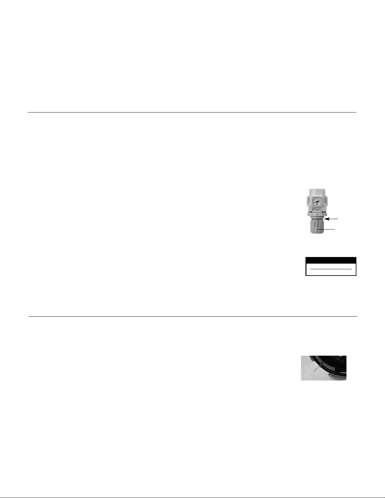
1. Regulation of air pressure is controlled by the knob found on the regulator portion of the FRL unit. The air pressure is measured by the gauge on the front.
2. To increase the air pressure, be sure to unlock the knob before adjusting. Pull the pressure regulator knob to unlock.
(You can visually verify this with the “orange mark” that appears in the gap). To decrease the air pressure, turn the knob
counterclockwise. Once the proper air pressure is established push the pressure regulator knob to lock. When the knob is
not easily locked, turn it left and right a little and then push it (when the knob is locked, the “orange mark,” i.e., the gap
will disappear).
3. Maximum operating air pressure is 150 PSIG.
Lubricator (Lubrication)
1. Oil fill port; An internal check valve allows oil to be added to the Lubricator oil reservoir bowl without shutting off the air supply and interruption to work operations.
2. Remove the fill cap plug by turning it counterclockwise.
3. Fill the bowl to the fill line with air tool oil. Use Dynabrade Air Lube 95842 or equivalent air tool oil (10W/NR).
4. Replace the fill plug by turning in clockwise.
5. After filling Lubricator bowl with oil, Oil Flow Adjustment Control, allows for easy, fast and accurate dispensing of oil.
6. Oil feed sight dome; Allows visible adjustment in the amount of dispensed oil (dropped) into the flow of compressed air.
7. Turn the sight dome valve clockwise to decrease oil drop rate and turn counterclockwise to increase oil drop rate. The higher the air flow (SCFM) rate, the
more the oil drop rate needs to be. With tool running, adjust to 1 drop per minute for each 20 SCFM of air flow. Flow rates for individual tools are supplied by
tool manufacture.
Maintenance Instructions:
Other than when adding oil to the lubricator, always turn off air pressure and discharge all air inside FRL unit before performing any maintenance procedures.
Filter:
1. Remove the filter bowl by sliding the silver lock button downward. Then rotate bowl clockwise or counterclockwise.
2. Remove filter module by visually noting the small locking feature visible through the view portion the top of the filter module.
The locking feature is a protrusion on the filter module and a groove in the metal bowl of the filter. Grip the filter module and
rotate it clockwise or counterclockwise such that the lock rotates out of the groove, rotate until you can see a wide clearance
notch completely fill the viewport then slide the filter module out of the metal bowl.
3. Inspect the filter assembly and check the amount of debris that may be collected on the filter cartridge itself. To remove filter element, rotate bottom of baffle
assembly counter clockwise quarter turn. Clean the filter with soap and water. If the filter is damaged or contains heavy debris, it must be replaced. Refer to
the parts breakdown for more information. Replace the element every 2 years or when the pressure drop becomes 15 PSIG (1 Bar), whichever comes first,
to prevent damage to the element.
4. Clean the filter bowl with soap and water. Replace bowl o-ring if damaged. Re-install bowl by rotating until the lock button locks into place.
Regulator:
1. No maintenance expected.
Lubricator:
1. Fill oil as required to fill line on bowl.
Products offered by Dynabrade should not be converted or otherwise altered from original design.
Orange mark
LUBRICATOR SETTING
1 DROP PER MINUTE
20 SCFM (566 LPM)
2
Knob
Page 3
Filter 10685
Regulator 10694
Lubricator 10687
Standard Specifications
Port Size 1/2"
Fluid Air
Proof Pressure 218 PSIG (15 Bar)
Max Operating Pressure 150 PSIG (10.3 Bar)
Ambient & Fluid Temperature 23 to 140˚F (-5 to 60˚C) [with no freezing]
Normal Filtration Rating 5µm
Bowl Material Zinc
Drain Capacity 1.52 oz. (45 cm
3
)
Weight 1.2 lb. (0.54 kg)
Standard Specifications
Port Size 1/2"
Fluid Air
Proof Pressure 218 PSIG (15 Bar)
Max Operating Pressure 150 PSIG (10.3 Bar)
Set Pressure Range 7 to 123 PSIG (8.5 bar)
Pressure Gauge Port Size N/A
Relief Pressure Set Pressure +7 PSIG (.5 Bar)
Ambient and Fluid Temperature 23 to 140˚F (-5 to 60˚C) [with no freezing]
Construction Relieving Type
Weight 1 lb. (0.44 kg)
Flow Characteristics
(Representative values)
Flow Characteristics
(Representative values)
Condition
Inlet Pressure: 102 PSIG (7 Bar)
Pressure Characteristics
(Representative values)
Condition
Inlet Pressure: 102 PSIG
Outlet Pressure: 29 PSIG
Flow Rate: .7 SCFM (20 L/Min.)
Standard Specifications
Port Size 1/2"
Fluid Air
Proof Pressure 218 PSIG (15 Bars)
Max Operating Pressure: 150 PSIG (10.3 Bars)
Oil Capacity 4.6 oz. (135 cm
3
)
Recommended Lubricant Dynabrade Air Lube (10W/NR)
Ambient and Fluid Temperature 23 to 140˚F (-5 to 60˚C)
[with no freezing]
Bowl Material Zinc
Weight 1.2 lb. (0.56 kg)
Flow Characteristics
(Representative values)
Condition
Inlet Pressure: 102 PSIG (7 Bar)
3
Page 4

Exemption from Liability
1. Dynabrade, Inc. is exempted from liability for any damages caused by operations not contained
in the catalogs and/or instruction manuals, and operations outside of the specification range.
2. Dynabrade, Inc. is exempted from liability for any loss or damage whatsoever caused by
malfunctions of its products when combined with other devices or software.
4
Safety Instructions
These safety instructions are intended to prevent hazardous situations and/or
equipment damage. These instructions indicate the level of potential hazard with
the labels of “Caution,” “Warning” or “Danger.” They are all important notes for
safety and must be followed in addition to International Standards (ISO/IEC)
1)
and other safety regulations.
,
Caution indicates a hazard with a low level of risk
Caution:
Warning
Danger :
which, if not avoided, could result in minor or
moderate injury.
Warning indicates a hazard with a medium level of
risk which, if not avoided, could result in death or
:
serious injury.
Danger indicates a hazard with a high level of risk
which, if not avoided, will result in death or serious
injury.
Warning
The compatibility of the product is the responsibility of the
person who designs the equipment or decides its specifications.
Since the product specified here is used under various operating conditions, its
compatibility with specific equipment must be decided by the person who designs
the equipment or decides its specifications based on necessary analysis and test
results. The expected performance and safety assurance of the equipment will be
the responsibility of the person who has determined its compatibility with the
product. This person should also continuously review all specifications of the
product referring to its latest catalog information, with a view to giving due
consideration to any possibility of equipment failure when configuring the
equipment.
Only personnel with appropriate training should operate
machinery and equipment.
The product specified here may become unsafe if handled incorrectly. The
assembly, operation and maintenance of machines or equipment including our
products must be performed by an operator who is appropriately trained and
experienced.
Do not service or attempt to remove product and machinery/
equipment until safety is confirmed.
The inspection and maintenance of machinery/equipment should only be
performed after measures to prevent falling or runaway of the driven objects
have been confirmed.
When the product is to be removed, confirm that the safety measures as
mentioned above are implemented and the power from any appropriate source
is cut, and read and understand the specific product precautions of all relevant
products carefully.
Before machinery/equipment is restarted, take measures to prevent
unexpected operation and malfunction.
Contact $YNABRADE)NC beforehand and take special
consideration of safetymeasures if the product is to be used
in any of the following conditions.
Conditions and environments outside of the given specifications, or use
outdoors or in a place exposed to direct sunlight.
Installation on equipment in conjunction with atomic energy, railways, air
navigation, space, shipping, vehicles, military, medical treatment, combustion
and recreation, or equipment in contact with food and beverages, emergency
stop circuits, clutch and brake circuits in press applications, safety equipment
or other applications unsuitable for the standard specifications described in the
product catalog.
An application which could have negative effects on people, property, or
animals requiring special safety analysis.
Use in an interlock circuit, which requires the provision of double interlock for
possible failure by using a mechanical protective function, and periodical
checks to confirm proper operation.
1) ISO 4414: Pneumatic fluid power – General rules relating to systems.
ISO 4413: Hydraulic fluid power – General rules relating to systems.
IEC 60204-1: Safety of machinery – Electrical equipment of machines.
(Part 1: General requirements)
ISO 10218-1: Manipulating industrial robots – Safety.
etc.
Caution
1. The product is provided for use in manufacturing industries.
The product herein described is basically provided for peaceful use in
manufacturing industries.
If considering using the product in other industries, consult $YNABRADE)NC
beforehand and exchange specifications or a contract if necessary.
If anything is unclear, contact your nearest sales branch.
Page 5

F.R.L. Unit Precautions 1
Be sure to read before handling
Design
Warning
1. The sight dome for the lubricator is made of polycarbonate.
Do not use in an environment where they are exposed to, or
come in contact with organic solvents, chemicals, cutting oil,
synthetic oil, alkali, and thread lock solutions.
2. Consult with Dynabrade, Inc. if the intended application calls for
absolutely zero leakage due to special atmospheric requirements,
or if the use of a fluid other than air is required.
3.
Regulator and Filter-Regulator
Be sure to install a safety device to prevent damage of malfunction
of the outlet side components when the output pressure exceeds
the set pressure value.
Selection
Warning
1. The mineral grease used on internal sliding parts and seals may
run down to outlet side components.
2. Regulator and Filter-Regulator
a. Residual pressure release (outlet pressure release) is not
complete by releasing the inlet pressure. To release residual
pressure, select a model with a back flow mechanism. Using a
model without a back flow mechanism makes for inconsistent
residual pressure release (i.e. residual pressure may or may not
be released) depending on the operating conditions.
b. Contact Dynabrade, Inc. if air will not be consumed in the
system for a long period of time, or if the outlet side will be used
with a sealed circuit and a balanced circuit, as this may cause
the set pressure of the outside to fluctuate.
c. Set the regulating pressure range for the outlet pressure of the
regulator in a range that is 85% or less of the inlet pressure. If
set to above 85%, the outlet pressure will be easily affected by
fluctuations in the flow rate and inlet pressure and become
unstable.
d. A safety margin is calculated into the maximum regulating
pressure range appearing in the catalog’s specification table.
However, the outlet pressure may exceed the set pressure due
to a delay in the valve’s closing.
e. Contact Dynabrade, Inc. when a circuit requires the use of a
regulator having relief sensitivity with high precision and
setting accuracy.
3. Lubricator
a. Contact Dynabrade, Inc. when the lubricator is used in high
frequency operations, such as in a press.
b. Lubrication cannot be properly performed if the operating flow
rate is too low. Select proper size lubricator by referring to the
minimum dripping flow rate provided in this catalog.
c. Avoid the use of a lubricator that causes back flow as this may
cause damage to internal parts.
d. Use a check valve to prevent the lubricant from back flowing
when redirecting the piping on the side.
5
Page 6

F.R.L. Unit Precautions 2
Be sure to read before handling
Mounting
Caution
1. To avoid reversed connections of the air inlet/outlet, make
connections after confirming the “IN/OUT” mark or arrows that
indicate the direction of air flow. Reversed connections can cause
malfunction.
2. Components with a bowl, e.g., air filter, filter regulator, lubricator,
must be installed vertically with the bowl downward so that faulty
drain discharge and dripping can be verified.
3. Ensure sufficient top, bottom, and front clearance for maintenance
and operation of each component. Refer to the dimensions section
for the minimum clearance for each component.
4. Regulator and Filter-Regulator
Be sure to unlock the knob before adjusting the pressure and to
lock it after the pressure is set.
5. When the bowl is installed on the air filter and/or lubricator, install
them so that the lock button lines up to the groove of the front
(or the back) of the body to avoid drop or damage of the bowl.
Adjustment
Warning
1. Regulator and Filter regulator
a. Set the regulator while verifying the displayed values of the inlet
and outlet pressure gauges. Turning the knob excessively can
cause damage to the internal parts.
b. Do not use a tool on the pressure regulator knob as this can
cause damage. It must be operated manually.
Caution
1. Regulator and Filter-Regulator
a. Be sure to check the inlet pressure before setting the outlet
pressure.
b. To set the pressure using the knob, turn the knob in the
direction that increases pressure and lock the knob after the
pressure is set. If this is done in the direction that decreases
pressure, the pressure may drop from the original set pressure.
Turning the knob clockwise increases the outlet pressure, and
turning it counterclockwise reduces the pressure.
Piping
Warning
1. To screw piping materials into components, tighten with a
recommended tightening torque while holding the female thread
side. If the minimum tightening torque is not observed, this can
cause a looseness and seal failure. On the other hand, excess
tightening torque can cause damage to the threads. Furthermore,
tightening without holding the female thread side can cause
damage due to the excess force that is applied directly to the
piping bracket.
Recommended tightening torque Unit: lb.- ft.
Connection Thread 3/8" 1/2"
Torque 16.2 to 17.7 20.6 to 22.1
* Alternatively tighten by hand, then tighten further approximately 1/6
turn using a tightening tool.
2. Avoid excessive torsional moment or bending moment other than
those caused by the equipment’s own weight as this can cause
damage. Support external piping separately.
3. Piping materials without flexibility such as steel tube piping are
prone to be affected by excess moment load and vibration from the
piping side. Use flexible tubing in between to avoid such an effect.
6
Lock Button
Page 7

Maintenance
Warning
1. When disassembly or installation is required during the
maintenance, repair, or replacement of a device, be sure to follow
the instructions provided in the instruction manual or safety
instructions in this catalog.
2. Perform periodical inspections to detect any cracks, scratches, or
other deterioration of the transparent sight dome of the lubricator.
Replace sight dome when any kind of deterioration is found,
otherwise this can cause damage.
3. Perform periodical inspections to detect dirt on the air filter, filter
regulator, and lubricator or the sight dome of the lubricator. When
you find dirt on any of the above devices, clean with a mild
household cleanser. Do not use other cleaning agents, otherwise
this can cause damage.
4.
Air Filter
a. Replace the element every 2 years or when the pressure drop
becomes 15 PSIG (1 Bar), whichever comes first, to prevent
damage to the element.
b. Release accumulated condensate periodically before it reaches
the maximum capacity. Condensate that flows out to the outlet
side can cause malfunctions.
Caution
1. Perform periodical inspections of the filter element and replace it
as necessary. Check the element whenever the outlet pressure
drops below normal or air does not flow smoothly during
operation.
2.
Regulator and Filter-Regulator
Check the sliding part or seat of the internal valve when a setting
malfunction or relief leakage occurs and temporary or emergency
repairs need to be made.
3.
Lubricator
Check the dripping amount once a day. Drip failure can cause
damage to the components being lubricated.
F.R.L. Unit Precautions 3
Be sure to read before handling
Piping
Caution
1. Lubricator
Try to avoid riser piping and branch lines as much as possible on
the outlet side, otherwise proper lubrication will be compromised.
Air Supply
Caution
1. When there is excessive condensate, install a device that
eliminates water such as a dryer or water separator (drain catch)
on the inlet side of the air filter.
7
Page 8

DYNABRADE, INC.,
8989 Sheridan Drive •Clarence, NY 14031-1490 •Phone: 716-631-0100 •Fax: 716-631-2073 •International Fax: 716-631-2524
© DYNABRADE, INC., 2016
Visit Our Web Site: www.dynabrade.com Email: Customer.Service@Dynabrade.com
Filter
Five-micron filter element is standard.
Manually rotate drain plug to discharge
contaminants.
Part No. 10685
Filter-Regulator
Unit has modular connections with
mounting brackets for easy installation.
Part No. 10688
Filter-Regulator-Lubricator
Unit has modular connections with
mounting brackets for easy installation.
Part No. 10690
Regulator-Lubricator
Unit has modular connections with
mounting brackets for easy installation.
Part No. 10689
Regulator
Compensation built into unit responds faster
to changes in incoming pressure and flow.
Built-in dual PSIG/Bar pressure dial guage.
Part No. 10694
Lubricator
Built-in check valve permits tool to be filled
with oil without having to turn off air pressure.
Adjustable oil drop to meter amount of oil
into air system.
Part No. 10687
Each unit includes two bushings for easy conversion to 3/8" NPT.
Additional Specifications: Maximum Operating Pressure
See Standard Specification Tables (Page 3).
Cost-Effective Maintenance for Air Supply Systems
Filter-Regulator-Lubricator
FRL Flow Characteristics (90 PSIG)
Flow
Pressure Drop
Across FRL
SCFM LPM PSIG Bar
15 425
0 —
30 850
2.0 0.14
45 1,274
2.0 0.14
60 1,699
4.0 0.28
75 2,124
5.0 0.34
DYNABRADE
®
 Loading...