

Page 1
MAINTENANCE 1
T
able Of Contents
SUBJECT PAGE NO.
1.1 General . . . . . . . . . . . . . . . . . . . . . . . . . . . . . . . . . . . . . . . . . . . . . . . . . . . . . . 1-1
1.2 Fuel and Oil . . . . . . . . . . . . . . . . . . . . . . . . . . . . . . . . . . . . . . . . . . . . . . . . . . . 1-5
1.3 Maintenance Schedule . . . . . . . . . . . . . . . . . . . . . . . . . . . . . . . . . . . . . . . . . . 1-6
1.4 Engine Oil and Filter . . . . . . . . . . . . . . . . . . . . . . . . . . . . . . . . . . . . . . . . . . . . 1-9
1.5 Battery Maintenance . . . . . . . . . . . . . . . . . . . . . . . . . . . . . . . . . . . . . . . . . . . . 1-12
1.6 Brakes . . . . . . . . . . . . . . . . . . . . . . . . . . . . . . . . . . . . . . . . . . . . . . . . . . . . . . . 1-15
1.7 Bleeding Brakes . . . . . . . . . . . . . . . . . . . . . . . . . . . . . . . . . . . . . . . . . . . . . . . 1-17
1.8 Brake Pads and Discs . . . . . . . . . . . . . . . . . . . . . . . . . . . . . . . . . . . . . . . . . . . 1-18
1.9 Tires and Wheels . . . . . . . . . . . . . . . . . . . . . . . . . . . . . . . . . . . . . . . . . . . . . . . 1-23
1.10 Primary Chain . . . . . . . . . . . . . . . . . . . . . . . . . . . . . . . . . . . . . . . . . . . . . . . . 1-25
1.11 Primary Chaincase Lubricant . . . . . . . . . . . . . . . . . . . . . . . . . . . . . . . . . . . . 1-26
1.12 Clutch . . . . . . . . . . . . . . . . . . . . . . . . . . . . . . . . . . . . . . . . . . . . . . . . . . . . . . 1-28
1.13 Transmission Lubricant . . . . . . . . . . . . . . . . . . . . . . . . . . . . . . . . . . . . . . . . . 1-30
1.14 Rear Belt Deflection . . . . . . . . . . . . . . . . . . . . . . . . . . . . . . . . . . . . . . . . . . . . 1-31
1.15 Rear Belt and Sprockets . . . . . . . . . . . . . . . . . . . . . . . . . . . . . . . . . . . . . . . . 1-33
1.16 Suspension Adjustments . . . . . . . . . . . . . . . . . . . . . . . . . . . . . . . . . . . . . . . . 1-35
1.17 Steering Head Bearings . . . . . . . . . . . . . . . . . . . . . . . . . . . . . . . . . . . . . . . . 1-36
1.18 Front Fork Oil . . . . . . . . . . . . . . . . . . . . . . . . . . . . . . . . . . . . . . . . . . . . . . . . . 1-37
1.19 Spark Plugs . . . . . . . . . . . . . . . . . . . . . . . . . . . . . . . . . . . . . . . . . . . . . . . . . . 1-38
1.20 Air Cleaner Filter . . . . . . . . . . . . . . . . . . . . . . . . . . . . . . . . . . . . . . . . . . . . . . 1-39
1.21 Cable and Chassis Lubrication . . . . . . . . . . . . . . . . . . . . . . . . . . . . . . . . . . . 1-41
1.22 Throttle Cables . . . . . . . . . . . . . . . . . . . . . . . . . . . . . . . . . . . . . . . . . . . . . . . 1-42
1.23 Engine Mounts . . . . . . . . . . . . . . . . . . . . . . . . . . . . . . . . . . . . . . . . . . . . . . . . 1-44
1.24 Headlamp Alignment . . . . . . . . . . . . . . . . . . . . . . . . . . . . . . . . . . . . . . . . . . . 1-45
1.25 Critical Fasteners . . . . . . . . . . . . . . . . . . . . . . . . . . . . . . . . . . . . . . . . . . . . . . 1-47
1.26 Storage . . . . . . . . . . . . . . . . . . . . . . . . . . . . . . . . . . . . . . . . . . . . . . . . . . . . . 1-48
1.27 Troubleshooting . . . . . . . . . . . . . . . . . . . . . . . . . . . . . . . . . . . . . . . . . . . . . . . 1-50
Page 2

Page 3

HOME
11WARNING1WARNING
1
GENERAL 1.1
SERVICING A NEW
SHOP PRACTICES
MOTORCYCLE
Repair Notes
NOTE
General maintenance practices are given in this section.
11WARNING1WARNING
Perform the service and maintenance operations as indicated in the regular service interval table. Lack of regular
maintenance at the recommended intervals can affect
the safe operation of your motorcycle, which could result
in death or serious injury. (00010a).
Service operations to be performed before customer delivery
are specified in the applicable model year PREDELIVERY
AND SETUP MANUAL.
The performance of new motorcycle initial service is required
to keep warranty in force and to ensure proper emissions systems operation.
After a new motorcycle has been driven its first 1000 miles
(1600 km), and at every 5000 mile (8000 km) interval thereafter, have a Harley-Davidson dealer perform the service operations listed under 1.3 MAINTENANCE SCHEDULE.
SAFE OPERATING
MAINTENANCE
CAUTION
●
Do not attempt to retighten engine head bolts.
Retightening can cause engine damage.
●
Repair = Disassembly/Assembly.
●
●
Replace = Removal/Installation.
All special tools and torque values are noted at the point of
use.
All required parts or materials can be found in the appropriate
PA RTS CATALOG.
Safety
Safety is always the most important consideration when performing any job. Be sure you have a complete understanding
of the task to be performed. Use common sense. Use the
proper tools. Protect yourself and bystanders with approved
eye protection. Don’t just do the job – do the job safely.
Removing Parts
Always consider the weight of a part when lifting. Use a hoist
whenever necessary. Do not lift heavy parts by hand. A hoist
and adjustable lifting beam or sling are needed to remove
some parts. The lengths of chains or cables from the hoist to
the part should be equal and parallel and should be positioned directly over the center of the part. Be sure that no
obstructions will interfere with the lifting operation. Never
leave a part suspended in mid-air.
During the initial 1000 mile (1600 km) break-in
●
period, use only Harley-Davidson 20W50 engine oil.
Failure to use the recommended oil will result in
improper break-in of the engine cylinders and piston
rings.
A careful check of certain equipment is necessary after periods of storage, and frequently between regular service intervals, to determine if additional maintenance is required.
Check:
1. Tires for abrasions, cuts and correct pressure.
2. Secondary drive belt for proper tension and condition.
3. Brakes, steering and throttle for responsiveness.
4. Brake fluid level and condition. Hydraulic lines and fittings for leaks. Also, check brake pads and rotors for
wear.
5. Cables for fraying, crimping and free operation.
6. Engine oil and transmission fluid levels.
7. Headlamp, passing lamp, tail lamp, brake lamp, horn and
turn signal operation.
Always check the capacity rating and condition of
hoists, slings, chains or cables before use. Failure to do
so could lead to an accident which could result in death
or serious injury.
Always use blocking or proper stands to support the part that
has been hoisted. If a part cannot be removed, verify that all
bolts and attaching hardware have been removed. Check to
see if any parts are in the way of the part being removed.
When removing hoses, wiring or tubes, always tag each part
to ensure proper installation.
Cleaning
If you intend to reuse parts, follow good shop practice and
thoroughly clean the parts before assembly. Keep all dirt out
of parts; the unit will perform better and last longer. Seals, filters and covers are used in this vehicle to keep out environmental dirt and dust. These items must be kept in good
condition to ensure satisfactory operation.
Clean and inspect all parts as they are removed. Be sure all
holes and passages are clean and open. After cleaning,
cover all parts with clean lint-free cloth, paper or other material. Be sure the part is clean when it is installed.
2006 Dyna: Maintenance 1-1
Page 4

HOME
Always clean around lines or covers before they are removed.
Plug, tape or cap holes and openings to keep out dirt, dust
and debris.
Always verify cleanliness of blind holes before assembly.
Tightening a screw with dirt, water or oil in the hole can cause
castings to crack or break.
Disassembly and Assembly
Always assemble or disassemble one part at a time. Do not
work on two assemblies simultaneously. Be sure to make all
necessary adjustments. Recheck your work when finished.
Be sure that everything is done.
Operate the vehicle to perform any final check or adjustments. If all is correct, the vehicle is ready to go back to the
customer.
REPAIR AND REPLACEMENT
PROCEDURES
Hardware and Threaded Parts
Install helical thread inserts when inside threads in castings
are stripped, damaged or not capable of withstanding specified torque.
Replace bolts, nuts, studs, washers, spacers and small common hardware if missing or in any way damaged. Clean up or
repair minor thread damage with a suitable tap or die.
Replace all damaged or missing lubrication fittings.
Use Teflon pipe sealant on pipe fitting threads.
Coat bearings with clean oil. Wrap bearings in clean paper.
Be sure that the chamfered side of the bearing always faces
the shoulder (when bearings installed against shoulders).
Lubricate bearings and all metal contact surfaces before
pressing into place. Only apply pressure on the part of the
bearing that makes direct contact with the mating part.
Always use the proper tools and fixtures for removing and
installing bearings.
Bearings do not usually need to be removed. Only remove
bearings if necessary.
Bushings
Do not remove a bushing unless damaged, excessively worn
or loose in its bore. Press out bushings that must be replaced.
When pressing or driving bushings, be sure to apply pressure
in line with the bushing bore. Use a bearing/bushing driver or
a bar with a smooth, flat end. Never use a hammer to drive
bushings.
Inspect the bushing and the mated part for oil holes. Be sure
all oil holes are properly aligned.
Gaskets
Always discard gaskets after removal. Replace with
kets. Unless otherwise instructed, never use the same gasket
twice. Be sure that gasket holes match up with holes in the
mating part. But be aware that sections of a gasket may be
used to seal passages.
new
gas-
Lip Type Seals
Wiring, Hoses and Lines
Replace hoses, clamps, electrical wiring, electrical switches
or fuel lines if they do not meet specifications.
Instruments and Gauges
Replace broken or defective instruments and gauges.
Replace dials and glass that are so scratched or discolored
that reading is difficult.
Bearings
Anti-friction bearings must be handled in a special way. To
keep out dirt and abrasives, cover the bearings as soon as
they are removed from the package.
Wash bearings in a non-flammable cleaning solution. Knock
out packed lubricant inside by tapping the bearing against a
wooden block. Wash bearings again. Cover bearings with
clean material after setting them down to dry. Never use compressed air to dry bearings.
Lip seals are used to seal oil or grease and are usually
installed with the sealing lip facing the contained lubricant.
Seal orientation, however, may vary under different applications.
Seals should not be removed unless necessary. Only remove
seals if required to gain access to other parts or if seal damage or wear dictates replacement.
Leaking oil or grease usually means that a seal is damaged.
Replace leaking seals to prevent overheated bearings.
Always discard seals after removal. Do not use the same seal
twice.
O-Rings (Preformed Packings)
Always discard O-rings after removal. Replace with
rings. To prevent leaks, lubricate the O-rings before installation. Apply the same type of lubricant as that being sealed.
Be sure that all gasket, O-ring and seal mating surfaces are
thoroughly clean before installation.
new
O-
1-2 2006 Dyna: Maintenance
Page 5

HOME
Gears
Always check gears for damaged or worn teeth.
Lubricate mating surfaces before pressing gears on shafts.
Shafts
If a shaft does not come out easily, check that all nuts, bolts
or retaining rings have been removed. Check to see if other
parts are in the way before using force.
Shafts fitted to tapered splines should be very tight. If shafts
are not tight, disassemble and inspect tapered splines. Discard parts that are worn. Be sure tapered splines are clean,
dry and free of burrs before putting them in place. Press mating parts together tightly.
Clean all rust from the machined surfaces of new parts.
Part Replacement
Always replace worn or damaged parts with
new
parts.
CLEANING
Part Protection
Before cleaning, protect rubber parts (such as hoses, boots
and electrical insulation) from cleaning solutions. Use a
grease-proof barrier material. Remove the rubber part if it
cannot be properly protected.
Cleaning Process
Any cleaning method may be used as long as it does not
result in parts damage. Thorough cleaning is necessary for
proper parts inspection. Strip rusted paint areas to bare metal
before repainting.
Rust or Corrosion Removal
TOOL SAFETY
Air Tools
Always use approved eye protection equipment when
●
performing any task using air-operated tools.
●
On all power tools, use only recommended accessories
with proper capacity ratings.
●
Do not exceed air pressure ratings of any power tools.
●
Bits should be placed against work surface before air
hammers are operated.
Disconnect the air supply line to an air hammer before
●
attaching a bit.
Never point an air tool at yourself or another person.
●
●
Protect bystanders with approved eye protection.
Wrenches
Never use an extension on a wrench handle.
●
●
If possible, always pull on a wrench handle and adjust
your stance to prevent a fall if something lets go.
●
Never cock a wrench.
Never use a hammer on any wrench other than a STRIK-
●
ING FACE wrench.
Discard any wrench with broken or battered points.
●
●
Never use a pipe wrench to bend, raise or lift a pipe.
Pliers/cutters/prybars
Plastic- or vinyl-covered pliers handles are not intended
●
to act as insulation; don’t use on live electrical circuits.
Don’t use pliers or cutters for cutting hardened wire
●
unless they were designed for that purpose.
●
Always cut at right angles.
●
Don’t use any prybar as a chisel, punch or hammer.
Remove rust and corrosion with a wire brush, abrasive cloth,
sand blasting, vapor blasting or rust remover. Use buffing crocus cloth on highly polished parts that are rusted.
Bearings
Clean open bearings by soaking them in a petroleum cleaning solution. Never use a solution that contains chlorine.
Let bearings stand and dry. Do not dry using compressed air.
Do not spin bearings while they are drying.
2006 Dyna: Maintenance 1-3
Page 6

HOME
Hammers
●
Never strike one hammer against a hardened object,
such as another hammer.
Always grasp a hammer handle firmly, close to the end.
●
Strike the object with the full face of the hammer.
●
●
Never work with a hammer which has a loose head.
Discard hammer if face is chipped or mushroomed.
●
Wear approved eye protection when using striking tools.
●
●
Protect bystanders with approved eye protection.
Punches/Chisels
●
Never use a punch or chisel with a chipped or mushroomed end; dress mushroomed chisels and punches
with a file.
Hold a chisel or a punch with a tool holder if possible.
●
●
When using a chisel on a small piece, clamp the piece
firmly in a vise and chip toward the stationary jaw.
●
Wear approved eye protection when using these tools.
Protect bystanders with approved eye protection.
●
Screwdrivers
●
Don’t use a screwdriver for prying, punching, chiseling,
scoring or scraping.
Use the right type of screwdriver for the job; match the tip
●
to the fastener.
Don’t interchange POZIDRIV®, PHILLIPS® or REED
●
AND PRINCE screwdrivers.
Screwdriver handles are not intended to act as insula-
●
tion; don’t use on live electrical circuits.
Don’t use a screwdriver with rounded edges because it
●
will slip – redress with a file.
Ratchets and Handles
●
Periodically clean and lubricate ratchet mechanisms with
a light grade oil. Do not replace parts individually; ratchets should be rebuilt with the entire contents of service
kit.
●
Never hammer or put a pipe extension on a ratchet or
handle for added leverage.
●
Always support the ratchet head when using socket
extensions, but do not put your hand on the head or you
may interfere with the action of its reversing mechanism.
●
When breaking loose a fastener, apply a small amount of
pressure as a test to be sure the ratchet’s gear wheel is
engaged with the pawl.
Sockets
●
Never use hand sockets on power or impact wrenches.
Select the right size socket for the job.
●
●
Never cock any wrench or socket.
●
Select only impact sockets for use with air or electric
impact wrenches.
Replace sockets showing cracks or wear.
●
Keep sockets clean.
●
●
Always use approved eye protection when using power
or impact sockets.
Storage Units
Don’t open more than one loaded drawer at a time.
●
Close each drawer before opening up another.
Close lids and lock drawers and doors before moving
●
storage units.
●
Don’t pull on a tool cabinet; push it in front of you.
●
Set the brakes on the locking casters after the cabinet
has been rolled to your work.
1-4 2006 Dyna: Maintenance
Page 7

HOME
FUEL AND OIL 1.2
FUEL
11WARNING1WARNING
Use care when refueling. Pressurized air in fuel tank can
force gasoline to escape through filler tube. Gasoline is
extremely flammable and highly explosive, which could
result in death or serious injury. (00029a)
11WARNING1WARNING
Avoid spills. Slowly remove filler cap. Do not fill above bottom of filler neck insert, leaving air space for fuel expansion. Secure filler cap after refueling. Gasoline is
extremely flammable and highly explosive, which could
result in death or serious injury. (00028a)
Use a good quality unleaded gasoline (91 pump octane or
higher). Octane ratings are usually shown on the gas pump.
GASOLINE BLENDS
ENGINE OIL
Use the proper grade of oil for the lowest temperature
expected before the next oil change.
If it is necessary to add oil and Harley-Davidson oil is not
available, use an oil certified for diesel engines. Acceptable
diesel engine oil designations include:
CF-4
●
●
CG-4
●
CH-4
CI-4
●
The preferred viscosities for the diesel engine oils, in
descending order, are:
●
20W-50
●
15W-40
10W-40
●
At the first opportunity, see a Harley-Davidson dealer to
change back to 100 percent Harley-Davidson oil.
See 1.4 ENGINE OIL AND FILTER for all service information.
WINTER LUBRICATION
CAUTION
Using gasoline that has an alcohol additive, such as
methanol, may cause fuel system rubber components’
failure and/or engine damage.
Harley-Davidson motorcycles were designed to give the best
performance using unleaded gasoline. Some fuel suppliers
sell gasoline/alcohol blends as a fuel. The type and amount of
alcohol added to the fuel is important.
●
DO NOT USE GASOLINES CONTAINING METHANOL.
Using gasoline/methanol blends will result in starting and
driveability deterioration and damage to critical fuel system components.
●
ETHANOL is a mixture of 10% ethanol (Grain alcohol)
and 90% unleaded gasoline. Gasoline/ethanol blends
can be used in your motorcycle if the ethanol content
does not exceed 10%.
REFORMULATED OR OXYGENATED GASOLINES
●
(RFG): “Reformulated gasoline” is a term used to
describe gasoline blends that are specifically designed to
burn cleaner than other types of gasoline. Your motorcycle will run normally using this type of gas.
Combustion in an engine produces water vapor. During starting and warm-up in cold weather, especially in freezing temperatures, the vapor condenses to water before the
crankcase is hot enough to exhaust it through the breather
system. If the engine is run long enough for the crankcase to
become thoroughly heated, the water returns to vapor and is
then exhausted.
An engine used for only short trips, and seldom allowed to
thoroughly warm up, accumulates increasing amounts of
water in the oil pan. Water mixed with oil forms a sludge that
causes accelerated engine wear. In freezing temperatures,
the water becomes slush or ice, which may clog oil lines and
result in engine failure.
Always change the engine oil more often in winter. If the
engine is used for short runs, change the oil even more frequently. The farther below freezing the temperature drops the
more often the oil should be changed.
You may find that some gasoline blends adversely affect the
starting, driveability or fuel efficiency of your bike. If you experience one or more of these problems, we recommend you try
a different brand of gasoline or gasoline with a higher octane
rating.
2006 Dyna: Maintenance 1-5
Page 8
HOME
MAINTENANCE SCHEDULE 1.3
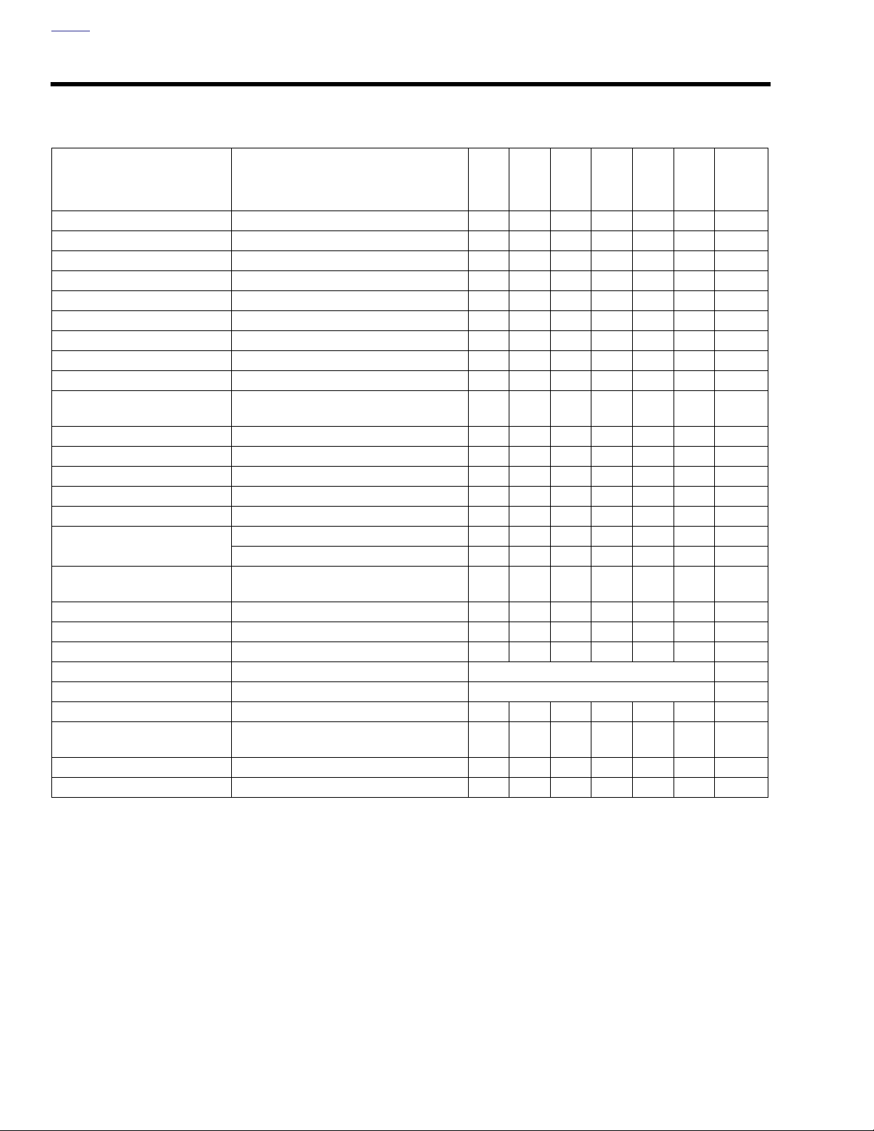
Table 1-1. Regular Service Intervals For Dyna Models
1000
5000
10,000
15,000
20,000
mi
mi
mi
km
mi
24,000
km
ITEM SERVICED PROCEDURE
1600
km
8000
km
16,000
Engine oil and filter Replace XXXXXX
Oil lines and brake system Inspect for leaks XXXXXX 1
Air cleaner Inspect, service as required XXXXXX
Tires Check pressure, inspect tread XXXXXX
Wheel spokes Check tightness X X X 1, 4
Primary chaincase lubricant Replace XXXXXX
Tr ansmission lubricant Replace XXXXXX
Clutch Check adjustment XXXXXX 1
Rear belt and sprockets Inspect, adjust belt XXXXXX 1
Throttle, brake and clutch con-
Check, adjust and lubricate XXXXXX1, 4
trols
Jiffy stand Inspect and lubricate X X X 1
Fuel lines and fittings Inspect for leaks XXXXXX1, 4
Fuel tank filter screen Replace X 1
Brake fluid Check levels and condition XXXXXX 5
Brake pads and discs Inspect for wear XXXXXX
Spark plugs Inspect X X X X
Replace X X
Electrical equipment and
Check operation XXXXXX
switches
Engine idle speed Check adjustment XXXXXX 1
Front fork oil Replace X 1
Steering head bearings Adjust X X X 1, 2
Rear fork bearings Inspect every 30,000 mi (48,000 km) 1
Primary chaincase bearing Replace every 15,000 mi (24,000 km) 6
Critical fasteners Check tightness X X X 1
Engine mounts and stabilizer
Inspect X X 1
links
Battery Check battery and clean connections 3
Road test Verify component and system functions XXXXXX
mi
32,000
km
25,000
mi
40,000
km
NOTES
NOTES:
1. Should be performed by an authorized Harley-Davidson dealer, unless you have the proper tools, service data and are
mechanically qualified.
2. Disassemble, lubricate and inspect every 30,000 miles (48,000 km).
3. Perform annually.
4. Not all vehicles are equipped with spoke wheels. Consult appropriate topic in service manual.
5. Replace D.O.T. 4 HYDRAULIC BRAKE FLUID and flush system every two years.
6. See an authorized Harley-Davidson dealer.
1-6 2006 Dyna: Maintenance
Page 9
HOME
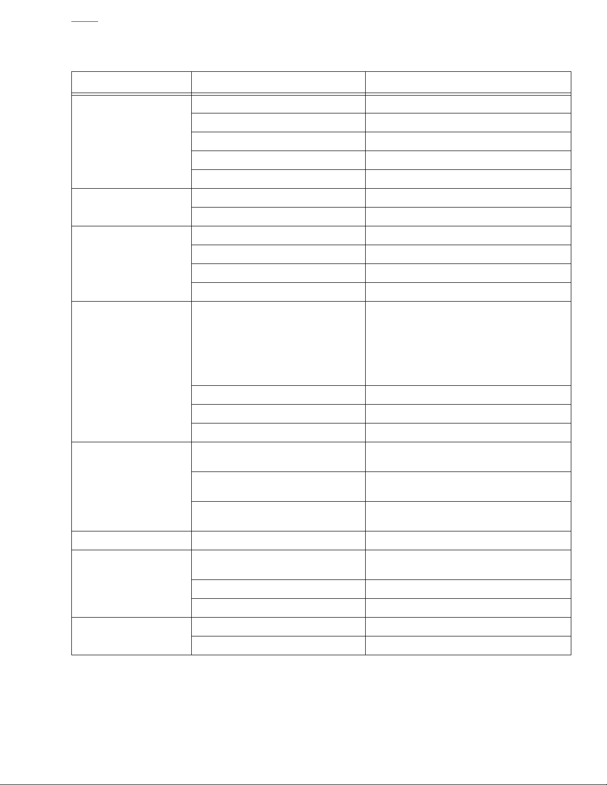
Table 1-2 Quick Reference Maintenance Chart
ITEM SERVICED SPECIFICATION DATA
Drain plug torque 14-21 ft-lbs (19.0-28.5 Nm)
Oil capacity 3 qt. (2.4 L)
Engine oil and filter
Primary chain lubricant
Clutch adjustment
Tr ansmission lubricant
Filter Hand tighten 1/2-3/4 turn after gasket contact
Chrome filter part number 63798-99
Black filter part number 63731-99
Lubricant capacity 32 oz. (0.95 liters)
Primary chaincase drain plug torque 36-60
Free play at adjuster screw 1/2-1 turn
Adjuster screw locknut torque 72-120
Free play at hand lever 1/16-1/8 (1.6-3.2 mm)
Clutch inspection cover torque 84-108
Lubricant level Check with motorcycle at normal operating tem-
Lubricant capacity 32 oz (0.95 liters)
Tr ansmission drain plug torque 14-21 ft-lbs (19.0-28.5 Nm)
in-lbs
(4.1-6.8 Nm)
in-lbs
(8.1-13.6 Nm)
in-lbs
(9.5-12.2 Nm)
perature and parked on jiffy stand. Remove and
wipe off dipstick. Place dipstick in filler hole with
filler plug resting on threads and remove. Lubricant level should be between upper and lower
ends of the oil level indicator marks on the dipstick.
Filler/check plug torque 25-75
Pressure for solo rider Front: 30 psi (207 kPA)
Rear: 36 psi (248 kPA)
Tire condition and pressure
Wheel spokes Spoke nipple torque 40-50
Brake fluid reservoir level
Brake pad linings and discs
Pressure for rider and passenger Front: 30 psi (207 kPA)
Rear: 40 psi (276 kPA)
Wear Replace tire if 1/32 in. (0.8 mm) or less of tread
pattern remains
D.O.T. 4 hydraulic brake fluid part numbers
Proper fluid level 1/8-1/4 in. (3.2-6.4 mm) below gasket surface
Master cylinder reservoir cover torque 6-8
Minimum brake pad thickness 0.04 in. (1.02 mm)
Minimum brake disc thickness See stamp on side of disc
99953-99A (12 oz.)
in-lbs
in-lbs
(2.8-8.5 Nm)
in-lbs
(4.5-5.6 Nm)
(0.7-0.9 Nm)
2006 Dyna: Maintenance 1-7
Page 10
HOME
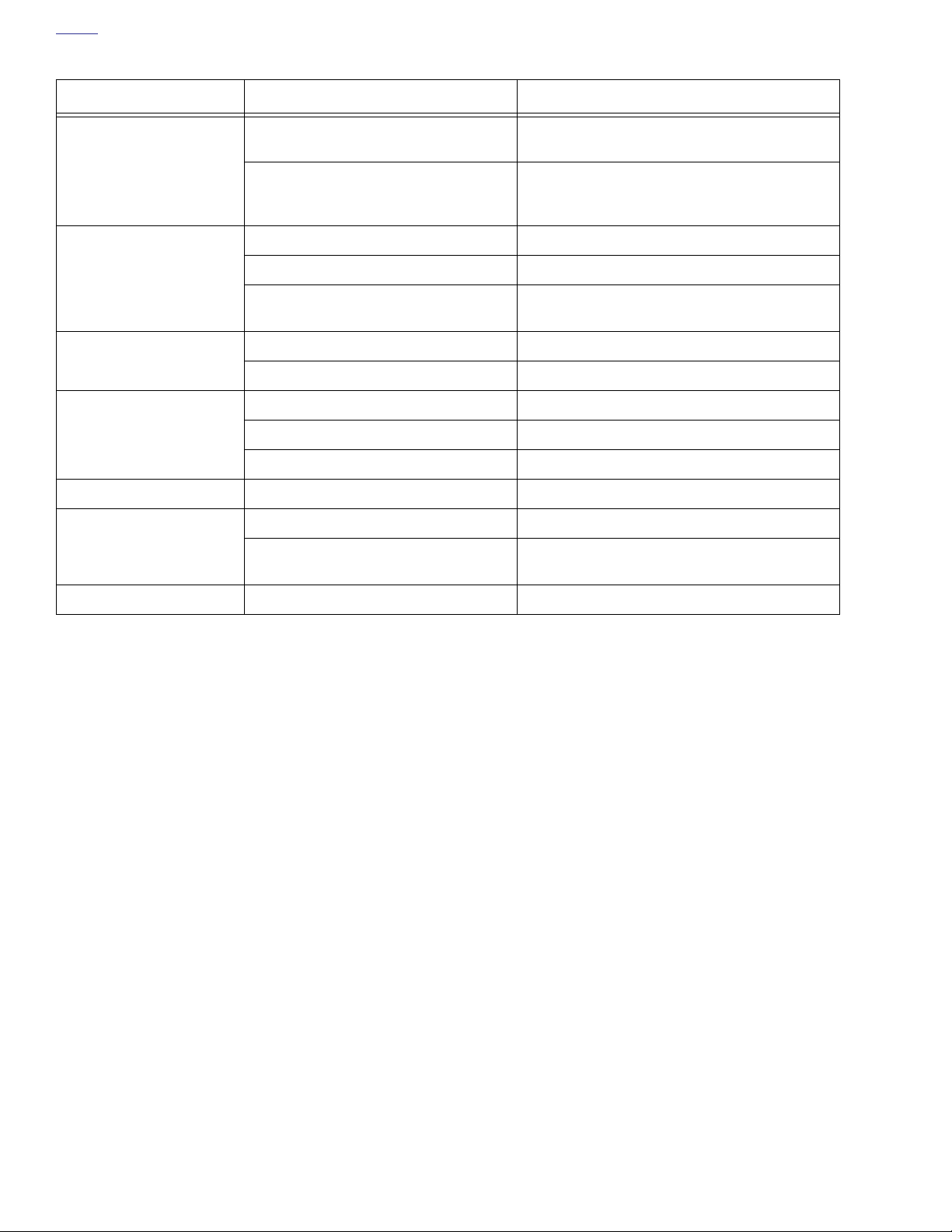
Table 1-2 Quick Reference Maintenance Chart
ITEM SERVICED SPECIFICATION DATA
Upward measurement force applied at
midpoint of bottom belt strand
Drive belt
Air cleaner
Clutch and throttle cables
Spark plugs
Engine idle speed Idle speed 950-1050 RPM
Front fork oil
Measure belt deflection with motorcycle
cold and the approximate weight of the
owner on motorcycle.
Air cleaner cover bracket screw torque 20-40
Air cleaner cover screw torque 36-60
Adhesive for air cleaner cover screw LOCTITE THREADLOCKER 243
Lubricant SUPER OIL Part No. 94968-85TV (1/4 fl. oz.)
Handlebar switch housing screw torque 35-45
Type HD-6R12
Gap 0.038-0.043 in. (0.97-1.09 mm)
Torque 12-18 ft-lbs (16.3-24.4 Nm)
Amount See section
Type
10 lb. (4.5 kg)
5/16-3/8 in. (7.9-9.5 mm)
in-lbs
(2.3-4.5 Nm)
in-lbs
(4.1-6.8 Nm)
Part No. 99642-97 (6 ml)
in-lbs
(4.0-5.1 Nm)
2.18 FRONT FORK
HYDRAULIC FORK OIL (TYPE E)
Part No. 99884-80 (16 oz.)
Battery Battery terminal torque 60-96
in-lbs
(6.8-10.9 Nm)
1-8 2006 Dyna: Maintenance
Page 11
11570
1
HOME
ENGINE OIL AND FILTER 1.4
CHECKING AND ADDING OIL
CAUTION
Oil level cannot be accurately measured on a cold
engine. For pre-ride inspection, with motorcycle leaning
on jiffy stand on level ground, oil should register on dipstick between arrows when engine is cold. Do not add oil
to bring the level to the FULL mark on a COLD engine.
(00185a)
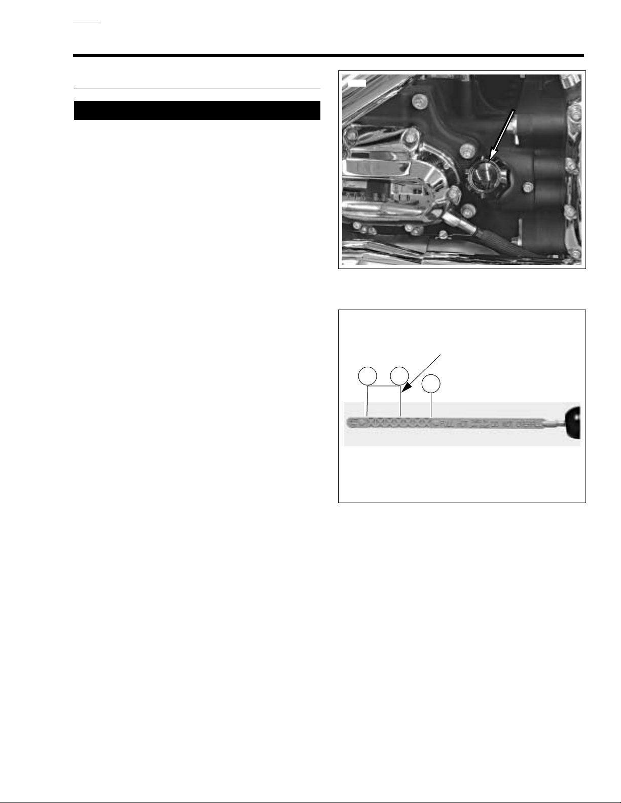
See Figure 1-1. Check engine oil level:
●
As part of the pre-ride inspection.
At each fuel fill
●
●
At every scheduled service interval.
Type of Oil
Refer to Ta ble 1-3. Use the proper grade of oil for the lowest
temperature expected before the next oil change. See 1.2
FUEL AND OIL for specific information regarding winter
needs.
If it is necessary to add oil and Harley-Davidson oil is not
available, use an oil certified for diesel engines. Acceptable
diesel engine oil designations include CF-4, CG-4, CH-4 and
CI-4. The preferred viscosities for the diesel engine oils, in
descending order, are 20W-50, 15W-40 and 10W-40. At the
first opportunity, see a Harley-Davidson dealer to change
back to 100 percent Harley-Davidson oil.
Checking With Cold Engine
1. See Figure 1-1. Unscrew and remove engine oil filler cap
with attached dipstick. Wipe dipstick clean.
2. Reinstall filler cap. Turn filler cap clockwise until it stops.
3. See Figure 1-2. Again, unscrew and remove filler cap
and check oil level on dipstick. If oil level in pan is below
lower mark on dipstick, add enough Harley-Davidson oil
to bring level up between lower mark (1) and cold check
level (2) on dipstick.
4. Replace filler cap and screw in securely.
Figure 1-1. Checking Engine Oil Level
11571a
For cold check level do not exceed
this point when filling with oil.
1 2
1. Lower arrow (add oil)
2. Cold check level
3. Upper arrow (hot check level)
Figure 1-2. Engine Oil Dipstick
3
NOTE
2006 Dyna: Maintenance 1-9
Page 12
HOME
Checking With Warm Engine
Ride motorcycle until engine is warmed up to operating
temperature, then do the following.
1. Idle motorcycle on jiffy stand for 1-2 minutes.
2. Shut motorcycle off and with motorcycle leaning on jiffy
stand on level ground, unscrew and remove engine oil
filler cap with attached dipstick. Wipe dipstick clean.
3. Reinstall filler cap. Turn filler cap clockwise until it stops.
4. See Figure 1-2. Again, unscrew and remove filler cap
and check oil level on dipstick. If oil level in pan is below
lower mark on dipstick, add enough Harley-Davidson oil
to bring level up between lower mark (1) and cold check
level (2) on dipstick.
5. Replace filler cap and screw in securely.
6. Add oil, if required, to FULL mark (3). Do not overfill.
CHANGING OIL AND FILTER
PART NO.
HD-42311 or
HD-44067
Oil filter wrench
SPECIALTY TOOL
Front of motorcycle
d0442x3x
1
2
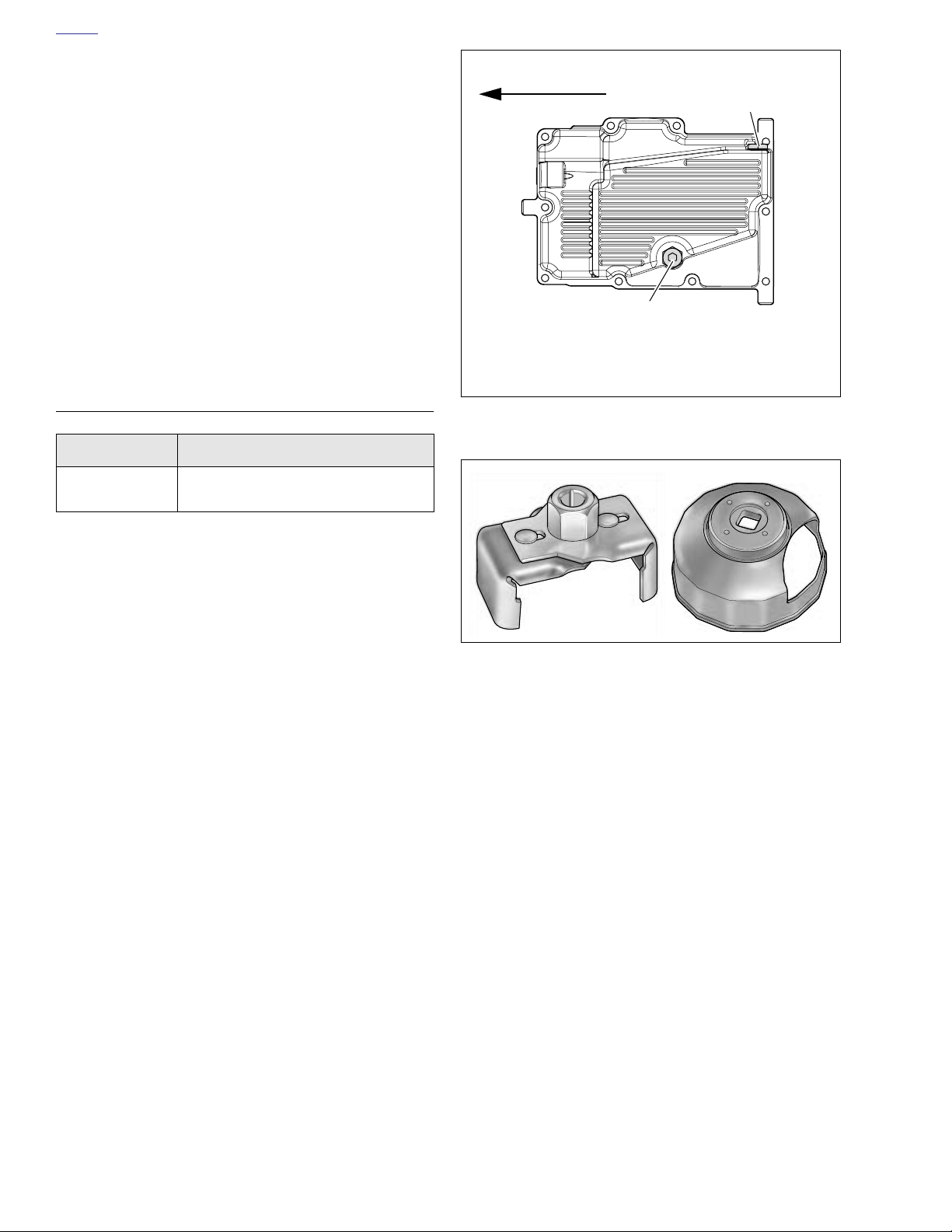
1. Engine oil drain plug and O-ring
@ 14-21 ft-lbs (19.0-28.5 Nm)
2. Transmission drain plug
Figure 1-3. Oil Pan
h42311 hd44067
NOTES
●
If the motorcycle is ridden hard, under dusty conditions,
or in cold weather, the oil and filter should be changed
more often.
●
All Dyna models are shipped from the factory with SAE
20W50 Harley-Davidson 360 Motor Oil.
●
All Dyna models come equipped from the factory with a
premium 5 micron synthetic media oil filter, Part No.
63798-99 (Chrome) or 63731-99 (Black). These are the
only recommended replacement filters.
1. Ride motorcycle until engine is warmed up to normal
operating temperature.
2. See Figure 1-1. Unscrew and remove engine oil filler cap
with attached dipstick.
3. See Figure 1-3. Remove the engine oil drain plug with Oring (1). Allow oil to drain into a suitable container.
Figure 1-4. Oil Filter Wrench
Part No. HD-42311 (left), HD-44067 (right)
1-10 2006 Dyna: Maintenance
Page 13
HOME
d0384x1x
CAUTION
Use Harley-Davidson oil filter wrench for filter removal,
which can prevent damage to crankshaft position sensor
and/or sensor cable.
Note
On vehicles equipped with forward controls, shift linkage may
have to be removed to provide enough clearance to remove
and install oil filter.
4. See Figure 1-4. Remove the oil filter using the OIL FIL-
TER WRENCH. Clean the oil filter mount flange of any
old gasket material.
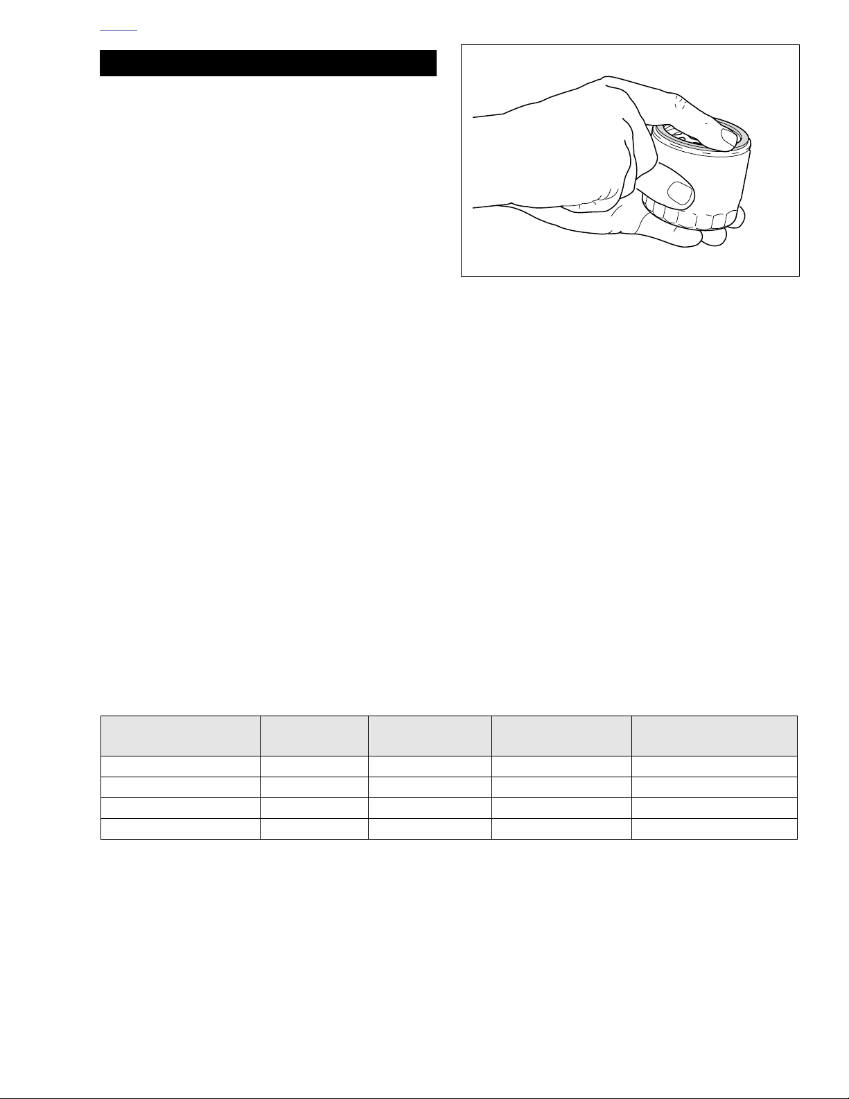
5. See Figure 1-5. Lube the gasket on
engine oil and install
to 3/4 turn after gasket contacts filter mounting surface.
Do NOT use oil filter wrench for oil filter installation.
6. See Figure 1-3. Install oil pan drain plug (1).
a. Inspect O-ring for tears or damage. Replace if
required. Wipe any foreign material from plug.
b. Install O-ring and drain plug. Tighten to 14-21 ft-lbs
(19.0-28.5 Nm).
7. See Figure 1-1. Fill oil pan with the correct amount of oil.
Use the proper grade of oil for the lowest temperature
expected before next oil change. Refer to Ta ble 1-3.
a. Use 2.5 quarts (2.4 liters) of engine oil for a wet
capacity refill.
b. Use 3.0 quarts (2.7 liters) for a dry capacity refill.
Use wet capacity for engines that have just had the oil
drained. Use dry capacity for engines that have been disassembled, cleaned in solvent and dried.
8. Check engine oil level using cold check procedure.
9. Start engine and carefully check for oil leaks around
drain plug and oil filter.
10. Check engine oil level using hot check procedure.
new
filter. Hand tighten oil filter 1/2
NOTE
new
oil filter with
Figure 1-5. Lubing New Oil Filter
Table 1-3. Recommended Oil Grades
HARLEY-DAVIDSON
TYPE
VISCOSITY
HARLEY-DAVID-
SON RATING
H.D. Multi-Grade SAE 10W40 HD 360 Below 40° F (4° C) Excellent
H.D. Multi-Grade SAE 20W50 HD 360 Above 40° F (4° C) Good
H.D. Regular Heavy SAE 50 HD 360 Above 60° F (16° C) Poor
H.D. Extra Heavy SAE 60 HD 360 Above 80° F (27° C) Poor
LOWEST AMBIENT
TEMP °F
2006 Dyna: Maintenance 1-11
COLD WEATHER STARTS
BELOW 50°F
Page 14
HOME
BATTERY MAINTENANCE 1.5
GENERAL
11WARNING1WARNING
Never remove warning label attached to top of battery.
Failure to read and understand all precautions contained
in warning, could result in death or serious injury.
(00064a)
11WARNING1WARNING
Batteries contain sulfuric acid, which could cause severe
burns to eyes and skin. Wear a protective face shield,
rubberized gloves and protective clothing when working
with batteries. KEEP BATTERIES AWAY FROM CHILDREN. (00063a)
All AGM batteries are permanently sealed, maintenance-free,
valve-regulated, lead/calcium and sulfuric acid batteries. The
batteries are shipped pre-charged and ready to be put into
service. Do not attempt to open these batteries for any reason.
d0424x1x
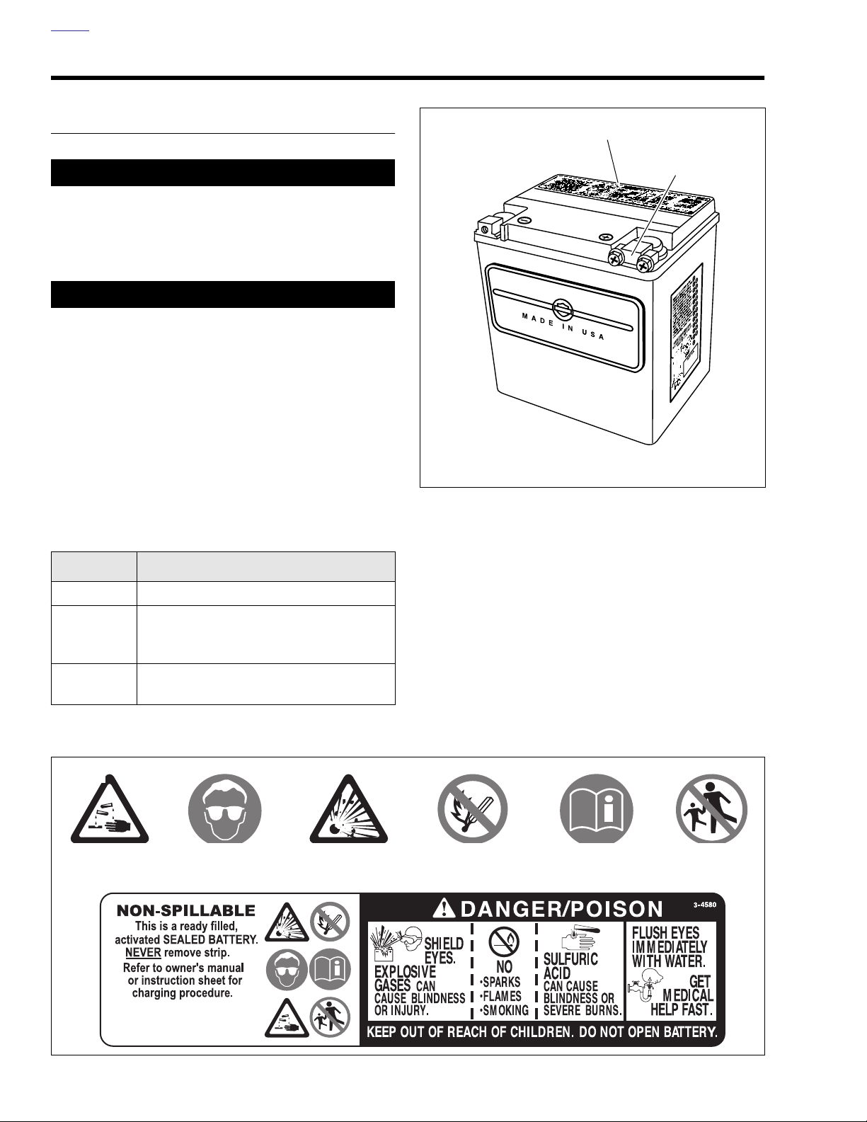
1. Warning label
2. Positive terminal cover
Figure 1-6. Battery
1
2
Table 1-4. Battery Electrolyte Antidotes
CONTACT
External Flush with water.
Internal Drink large quantities of milk or water,
followed by milk of magnesia, vegetable oil
or beaten eggs. Call doctor immediately.
Eyes Flush with water, get immediate medical
attention.
d0425a1x
Contents
are Corrosive.
Safety Glasses.
SOLUTION
Wear
Contents
are Explosive.
NOTE
See 8.12 BATTERY for charging and testing information.
Keep
Flames Away.
Read
Instructions.
Keep Away
From Children.
1-12 2006 Dyna: Maintenance
Figure 1-7. Battery Warning Label
Page 15
HOME
11WARNING1WARNING
DISCONNECTION AND REMOVAL
1. Remove seat.
11WARNING1WARNING
Disconnect negative (-) battery cable first. If positive (+)
cable should contact ground with negative (-) cable connected, the resulting sparks can cause a battery explosion, which could result in death or serious injury.
(00049a)
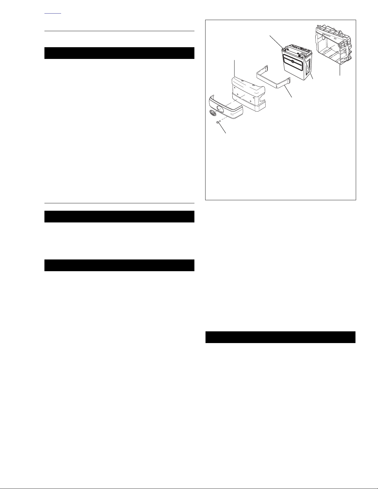
2. See Figure 1-8. Remove lower fastener (1).
3. Pivot cover (2) outward and lift to disengage slots on
cover from projections on battery tray (3).
4. Unthread and remove battery negative cable from nega-
tive battery terminal (4).
5. Unbolt and remove battery positive cable from positive
(+) battery terminal (5).
6. Remove battery strap (6).
7. Remove battery from tray.
INSTALLATION AND
CONNECTION
k00471g
4
2
1
1. Screw
2. Cover
3. Battery tray
4. Negative battery terminal
5. Positive battery terminal
6. Battery strap
7. Battery terminal cover
Figure 1-8. Battery Assembly
MADE IN
E
D
e
g
Y
r
C
a
I
h
L
c
O
O
t
P
u
T
o
N
N
h
t
E
i
M
r
w
T
o
d
S
s
l
e
U
a
c
J
i
C
f
r
a
D
l
e
o
A
t
p
a
e
e
D
t
O
r
e
a
m
N
t
e
d
A
a
n
i
b
d
Y
l
m
l
e
T
i
o
v
m
r
i
N
w
f
t
o
A
r
c
f
y
s
R
6
e
E
r
f
h
s
R
r
t
e
e
t
h
e
A
n
t
e
l
t
d
t
l
S
f
o
i
h
n
a
W
e
t
A
b
o
w
m
b
f
.
s
o
m
2
y
e
i
o
r
t
s
1
s
h
6
e
a
d
h
t
T
r
p
t
h
t
i
n
o
n
c
a
h
u
r
o
U
e
s
b
u
o
s
f
n
m
p
e
a
a
f
n
d
i
r
2
A
h
h
o
e
t
m
e
c
1
t
g
r
k
,
d
n
r
r
u
e
e
e
a
u
o
h
p
s
t
s
h
o
w
a
e
c
a
c
l
n
h
-
i
r
b
c
e
i
c
h
e
r
t
h
h
Y
p
s
i
t
i
u
e
a
-
w
h
v
p
r
h
J
t
s
e
c
r
r
n
u
r
v
r
e
e
u
t
b
o
u
n
t
p
,
n
f
e
e
s
l
o
u
w
e
f
r
h
b
o
h
o
o
t
f
t
a
c
n
f
o
r
s
-
d
o
o
h
e
e
e
U
f
t
n
m
h
d
n
a
s
m
t
i
US
-
o
o
J
n
t
i
r
d
r
a
e
e
e
m
,
r
e
c
t
v
h
f
s
t
a
p
r
t
l
o
o
t
o
o
p
r
e
t
a
e
n
e
a
h
r
e
t
b
n
s
c
Y
e
i
r
e
i
m
.
r
b
v
o
y
u
e
f
p
t
u
j
s
n
r
n
y
e
u
l
M
a
r
e
a
l
b
n
r
f
h
u
a
r
t
o
A
o
g
r
a
r
e
e
o
e
r
w
s
v
t
e
u
c
s
i
d
h
e
e
t
l
P
e
h
t
h
g
T
t
a
e
r
.
y
n
N
o
y
b
t
,
r
e
p
n
t
d
O
a
y
e
l
r
d
1
r
o
i
S
a
o
tr
0
v
c
w
AA
2
D
e
s
l
i
I
e
3
d
r
V
5
n
e
M
a
p
I
A
o
r
1234567890
.
p
D
A
W
-
m
i
Y
.
,
E
S
E
E
.
F
E
L
U
K
N
R
I
U
A
E
A
D
H
A
A
W
J
M
L
I
M
.
O
N
T
R
A
P
3
5
6
CAUTION
Do not over-tighten bolts on battery terminals. Use recommended torque values. Over-tightening battery terminal bolts could result in damage to battery terminals.
(00216a)
11WARNING1WARNING
Connect positive (+) battery cable first. If positive (+)
cable should contact ground with negative (-) cable connected, the resulting sparks can cause a battery explosion, which could result in death or serious injury.
(00068a)
NOTE
Check that battery is fully charged before installation.
1. See Figure 1-8. With battery terminals facing outward,
place battery in battery tray and install battery strap.
2. Insert fastener through battery positive cable terminal
and into threaded hole of battery positive (+) terminal (5).
Tighten fastener to 60-96
in-lbs
(6.8-10.9 Nm). Place
battery terminal cover over positive battery terminal.
3. Insert fastener through battery negative cable terminal
into threaded hole of battery negative (–) terminal (4).
Tighten fastener to 60-96
in-lbs
(6.8-10.9 Nm).
4. Apply a light coat of petroleum jelly or corrosion retardant
material to both battery terminals.
5. Place slots on battery cover (2) on projections on battery
tray (3). Install screw (1) to secure cover.
After installing seat, pull upward on front of seat to be
sure it is in locked position. While riding, a loose seat can
shift causing loss of control, which could result in death
or serious injury. (00070a)
6. Install seat.
2006 Dyna: Maintenance 1-13
Page 16
HOME
INSPECTION
1. Battery top must be clean and dry. Dirt and electrolyte on
top of the battery can cause battery to self-discharge.
Clean battery top with a solution of baking soda (sodium
bicarbonate) and water (5 teaspoons baking soda per
quart or liter of water). When the solution stops bubbling,
rinse off the battery with clean water.
2. Clean cable connectors and battery terminals using a
wire brush or sandpaper. Remove any oxidation.
3. Inspect the battery screws, clamps and cables for breakage, loose connections and corrosion. Clean clamps.
4. Check the battery posts for melting or damage caused
by overtightening.
5. Inspect the battery for discoloration, raised top or a
warped or distorted case, which might indicate that the
battery has been frozen, overheated or overcharged.
6. Inspect the battery case for cracks or leaks.
STORAGE
11WARNING1WARNING
Batteries contain sulfuric acid, which could cause severe
burns to eyes and skin. Wear a protective face shield,
rubberized gloves and protective clothing when working
with batteries. KEEP BATTERIES AWAY FROM CHILDREN. (00063a).
d0426x1x
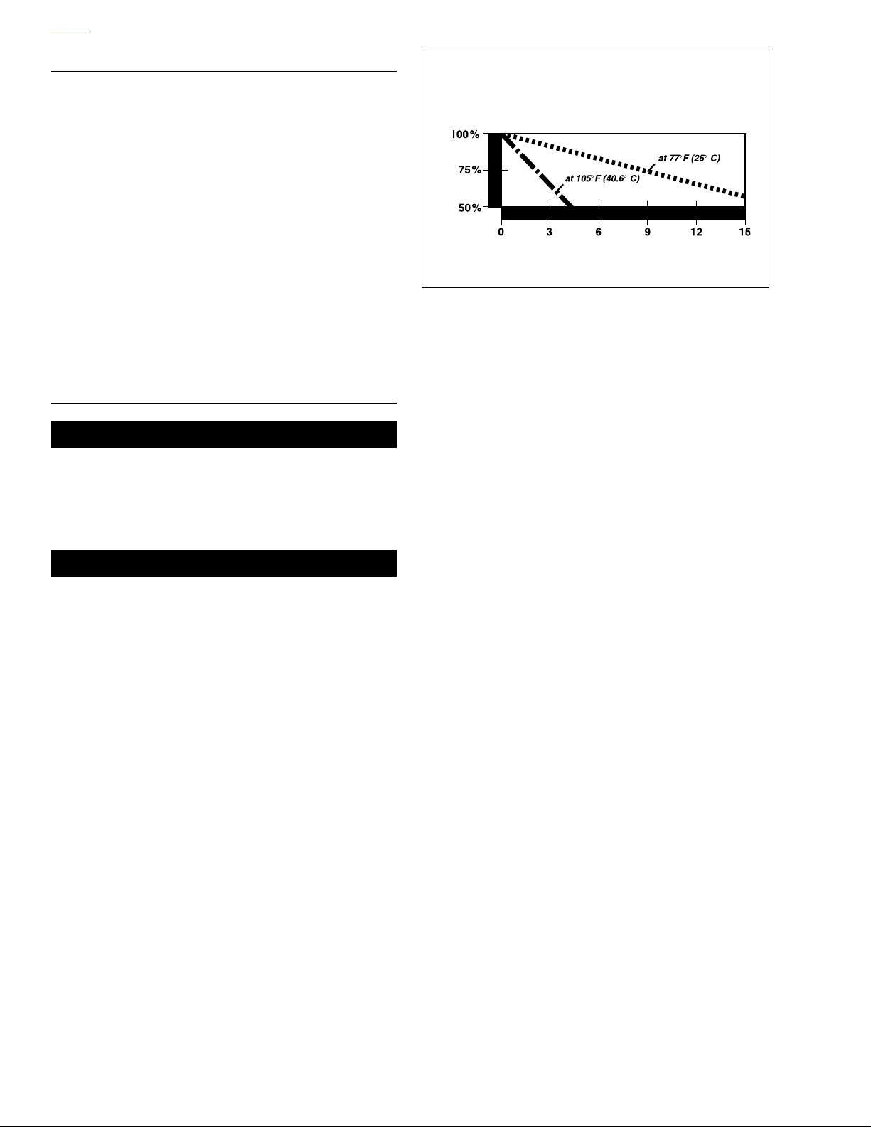
Effect of temperature on
battery self-discharge rate
C
a
p
a
c
i
t
y
Months of stand
Figure 1-9. Battery Self-Discharge Rate
CAUTION
Do not allow battery to completely discharge. The electrolyte in a discharged battery will freeze. The more discharged a battery is, the more easily it can freeze and
crack the battery case. (00218a)
If the motorcycle will not be operated for several months,
such as during the winter season, remove the battery from
the motorcycle and fully charge. See 8.12 BATTERY.
See Figure 1-9. Self-discharge is a normal condition and
occurs continuously at a rate that depends on the ambient
temperature and the battery’s state of charge. Batteries discharge at a faster rate at higher ambient temperatures. To
reduce the self-discharge rate, store battery in a cool (not
freezing), dry place.
Charge the battery every month if stored at temperatures
below 60˚ F (16˚ C). Charge the battery more frequently if
stored in a warm area above 60˚ F (16˚ C).
NOTES
The GLOBAL BATTERY CHARGER (Part No. 99863-01A)
may be used to maintain battery charge for extended periods
of time without risk of overcharging or boiling.
When returning a battery to service after storage, refer to the
instructions under 8.12 BATTERY.
1-14 2006 Dyna: Maintenance
Page 17
HOME
d0678x1x
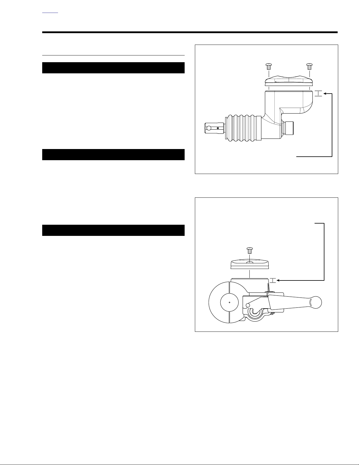
Fluid level should be
1/8-1/4 in. (3.2-6.4 mm) below
gasket surface
d0597x1x
Fluid level should be
1/8-1/4 in. (3.2-6.4 mm) below
gasket surface
BRAKES 1.6
FLUID INSPECTION
1CAUTION
Direct contact of D.O.T. 4 brake fluid with eyes can cause
irritation. Avoid eye contact. In case of eye contact flush
with large amounts of water and get medical attention.
Swallowing large amounts of D.O.T. 4 brake fluid can
cause digestive discomfort. If swallowed, obtain medical
attention. Use in well ventilated area. KEEP OUT OF
REACH OF CHILDREN. (00240a)
1. See Figure 1-10. Check level in rear brake master cylinder reservoir. Level should be 1/8-1/4 in. (3.2-6.4 mm)
below the gasket surface.
CAUTION
Do NOT allow dirt or debris to enter the master cylinder
reservoir. Dirt or debris in the reservoir can cause
improper operation and equipment damage. (00205b)
2. See Figure 1-11. Check level in front brake master cylinder reservoir. Level should be 1/8-1/4 in. (3.2-6.4 mm)
below the gasket surface.
3. Install gaskets and covers. Tighten reservoir cover
screws to 6-8
in-lbs
(0.7-0.9 Nm).
Figure 1-10. Rear Brake Master Cylinder Reservoir
11WARNING1WARNING
After repairing the brake system, test brakes at low
speed. If brakes are not operating properly, testing at
high speeds can cause loss of control, which could
result in death or serious injury. (00289a)
4. Front brake hand lever and rear brake foot pedal must
have a firm feel when applied. If not, bleed system using
only D.O.T. 4 BRAKE FLUID. See 1.7 BLEEDING
BRAKES.
Figure 1-11. Front Brake Master Cylinder Reservoir
2006 Dyna: Maintenance 1-15
Page 18
HOME
REAR PEDAL HEIGHT
The rear brake pedal should not require adjustment. If minor
pedal height adjustment is desired:
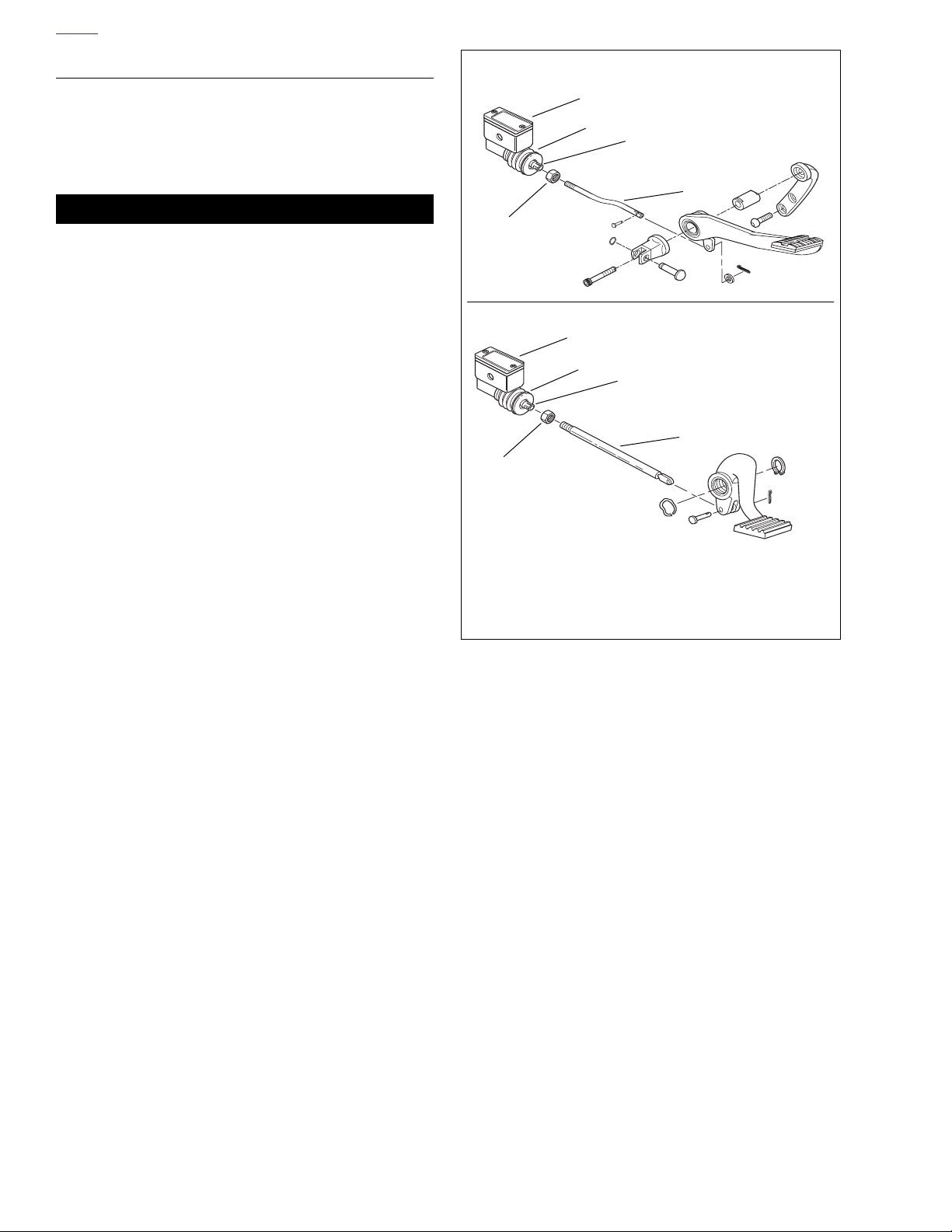
1. See Figure 1-12. Brake rod (5) is threaded into push rod
(3) in rear brake master cylinder (1), and locked in place
with jam nut (4). Loosen jam nut.
11WARNING1WARNING
When adjusting brake control rod, never allow more than
six threads to be exposed between control rod and jam
nut. If more than six threads are exposed, brake rod can
come apart resulting in loss of rear brake, which could
cause death or serious injury. (00306a)
2. Using an open-end wrench on the push rod flats, turn the
push rod in the direction which will correct pedal height.
When correct pedal height is obtained, tighten jam nut.
3. Verify that water drain hole in rubber boot (2), which covers rear brake push rod, is positioned to bottom.
NOTE
Brake pedal freeplay is built into master cylinder and no
adjustment is required. When pedal is pushed down with
hand, a small amount of freeplay must be felt.
FXDWG model
4
4
d0431b1x
1
2
3
5
All models but FXDWG
1
2
3
5
1. Rear brake master cylinder
2. Rubber boot
3. Push rod
4. Jam nut
5. Brake rod
Figure 1-12. Rear Brake Pedal Height
1-16 2006 Dyna: Maintenance
Page 19
HOME
11WARNING1WARNING
7400
7425
BLEEDING BRAKES 1.7
GENERAL
1CAUTION
Direct contact of D.O.T. 4 brake fluid with eyes can cause
irritation. Avoid eye contact. In case of eye contact flush
with large amounts of water and get medical attention.
Swallowing large amounts of D.O.T. 4 brake fluid can
cause digestive discomfort. If swallowed, obtain medical
attention. Use in well ventilated area. KEEP OUT OF
REACH OF CHILDREN. (00240a)
Front brake hand lever and rear brake foot pedal must have a
firm feel when brakes are applied. If not, bleed system as
described.
PROCEDURE
Figure 1-13. Front Brake Bleeder Valve
NOTE
Hydraulic brake fluid bladder-type pressure equipment can be
used to fill brake master cylinder through the bleeder valve.
Remove master cylinder reservoir cover so that system cannot pressurize. Do not use pressure bleeding equipment
when the hydraulic system is sealed with master cylinder reservoir cover and gasket in place.
1. Remove bleeder valve cap. Install end of a length of clear
plastic tubing over caliper bleeder valve; place other end
in a clean container. Stand motorcycle upright.
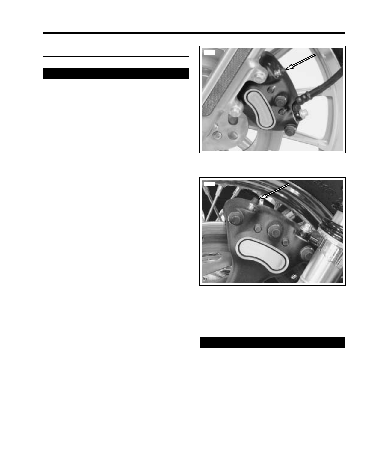
a. Front brake bleeder valve-see Figure 1-13.
b. Rear brake bleeder valve-see Figure 1-14.
2. Add D.O.T. 4 BRAKE FLUID to master cylinder reservoir.
Fluid level should be 1/8-1/4 in. (3.2-6.4 mm) below the
gasket surface. Depress and hold brake lever/pedal to
build up hydraulic pressure.
3. Open bleeder valve slowly about 1/2-turn counterclockwise; brake fluid will flow from bleeder valve and through
tubing. When brake lever/pedal has moved its full range
of travel, close bleeder valve (clockwise). Allow brake
lever/pedal to return slowly to its released position.
Figure 1-14. Rear Brake Bleeder Valve
4. Repeat Steps 2-3 until all air bubbles are purged.
5. Tighten bleeder valve to 80-100
Install bleeder valve cap.
6. Verify master cylinder fluid level as described in Step 2.
After repairing the brake system, test brakes at low
speed. If brakes are not operating properly, testing at
high speeds can cause loss of control, which could
result in death or serious injury. (00289a)
7. Attach covers to master cylinder reservoirs. Tighten
screws on covers to 6-8
in-lbs
in-lbs
(9.0-11.3 Nm).
(0.7-0.9 Nm).
2006 Dyna: Maintenance 1-17
Page 20
HOME
BRAKE PADS AND DISCS 1.8
INSPECTION
Check brake pads and discs:
●
At every scheduled service interval.
Whenever the components are removed during service
●
procedures.
Brake Pads
11WARNING1WARNING
Always replace brake pads in complete sets for correct
and safe brake operation. Improper brake operation
could result in death or serious injury. (00111a)
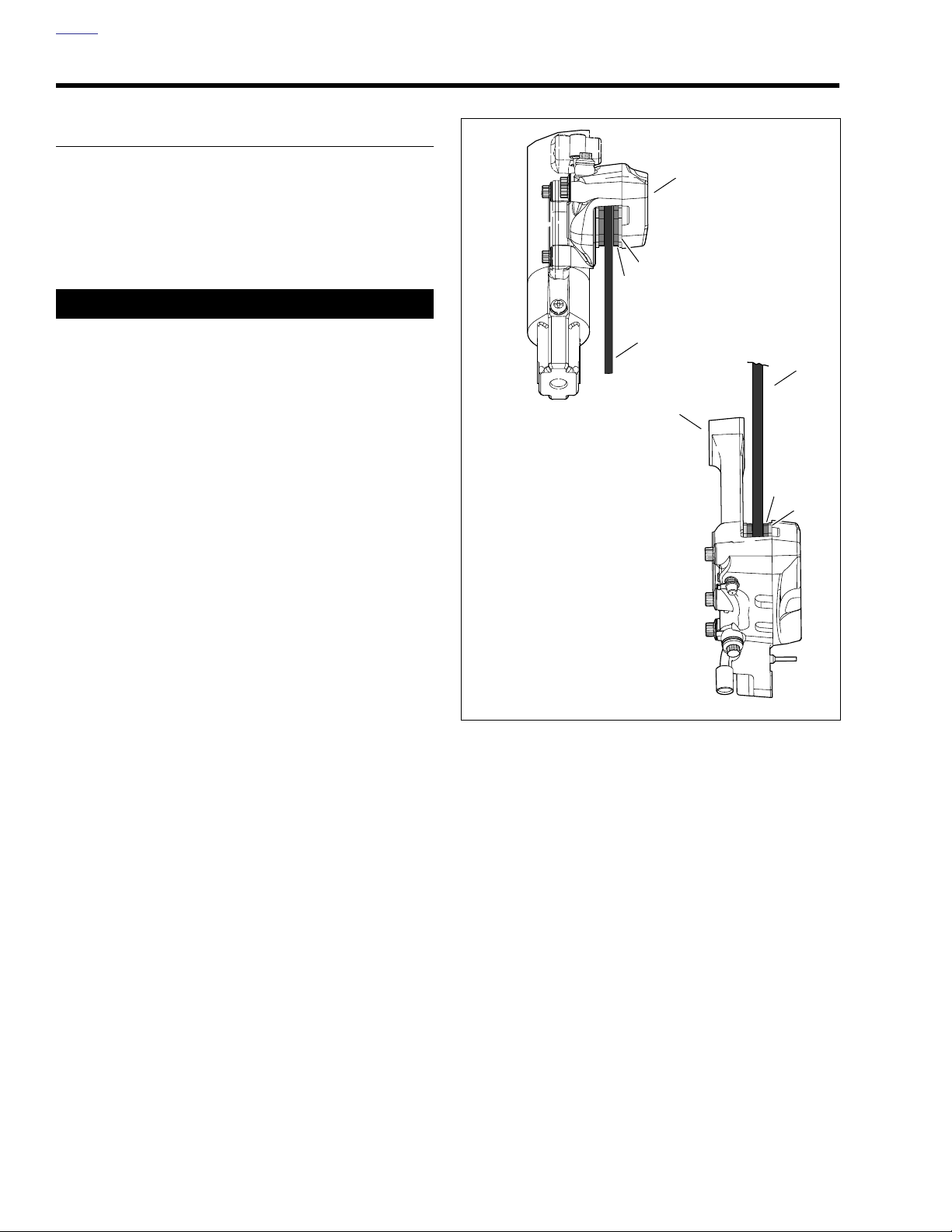
See Figure 1-15. Replace brake pads (3) if brake pad friction
material on either the front or rear caliper is worn to 0.04 in.
(1.02 mm) or less above the backing plate (4). Always replace
both pads in a caliper as a set. See BRAKE PAD REPLACE-
MENT below.
When checking the brake pads and discs, inspect the brake
hoses for correct routing and any signs of damage.
Brake Disc Thickness
The minimum brake disc (2) thickness is stamped on the side
of the disc. Replace disc if badly scored.
Brake Disc Lateral Runout and Warpage
Maximum brake disc lateral runout and warpage is 0.008 in.
(0.2 mm) when measured near the outside diameter.
d0396x1x
1
4
3
2
2
5
3
4
1. Front brake caliper
(viewed from below)
2. Brake disc
3. Brake pads
4. Backing plate
5. Rear brake caliper
(viewed from above)
Figure 1-15. Brake Pad Inspection
1-18 2006 Dyna: Maintenance
Page 21
HOME
7425
d0558a2x
1. Two tabs on backing plate
2. Single square tab on backing plate
3. Curved portion
1
2
3
BRAKE PAD REPLACEMENT
Rear Brake Caliper
1. If present, remove right saddlebag.
2. Remove the rear master cylinder reservoir cap. As the
pistons are pushed back into the caliper, fluid level may
rise more than 1/8 in. (3.2 mm). You may have to remove
fluid to allow for this.
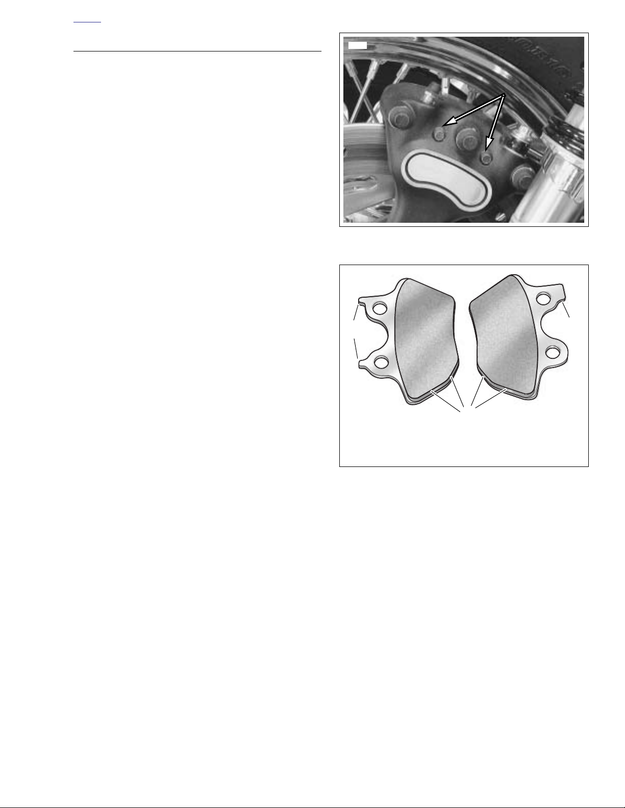
3. See Figure 1-16. Loosen, but do not remove, both pad
pins (12 pt/0.25 in.).
4. Pry the inside pad back. Use steady pressure to prevent
scoring the brake disc. Pry between the pad and the
brake disc in order to push the caliper pistons back into
their bores.
NOTE
Do not completely pull pad pins from caliper during the next
step. Completely removing pad pins at this time will cause difficulty during assembly.
5. Once the pistons have been fully retracted into their
bores, pull pad pins part way until the inside pads drop
free. Note the pad’s original orientation for replacement
purposes.
NOTE
See Figure 1-17. The front left, front right (not present on all
vehicles) and rear brake calipers use the same exact brake
pad set. Install pad with two tabs (1) on the inboard side of
the rear caliper.
6. Install
7. Install pad pins until the pins snap into place with an
8. Pump brake pedal lever to move inside pistons out until
9. Pry the outside pad back. Pry between the pad and the
10. Verify that inside pads are captured between brake disc
new
inside brake pad using the same orientation
as the pad previously removed. Curved portion of pad
must face rear of motorcycle.
audible click. Do not fully tighten at this time.
they contact inside brake pads.
brake disc in order to push the caliper pistons back into
their bores.
and pistons. Completely remove pad pins to free outside
brake pad. Note the pad’s original orientation for replacement purposes.
Figure 1-16. Pad Retaining Pins
(Rear Caliper Shown)
Figure 1-17. Brake Pad Orientation
2006 Dyna: Maintenance 1-19
Page 22
HOME
11. Inspect pad pins for grooving and wear. Measure the pad
pin diameter in an unworn area, and then in the area of
any grooving or wear. If wear is more than 0.015 in. (0.38
mm), replace both pins.
12. Install
13. Install both pad pins through holes in inner and outer
new
outside brake pad using the same orientation
as the pad previously removed. If the inside pad moved
during the previous step, reinstall. Curved portion of pad
must face rear of motorcycle.
brake pads. Tighten to 180-200
in-lbs
(20.3-22.6 Nm).
11WARNING1WARNING
After servicing brakes and before moving motorcycle,
pump brakes to build brake system pressure. Insufficient
pressure can adversely affect brake performance, which
could result in death or serious injury. (00279a)
14. Pump brake pedal to move pistons out until they contact
both brake pads. Verify piston location against pads.
15. Check brake fluid level in master cylinder. Fill to proper
level if necessary using D.O.T. 4 BRAKE FLUID. Install
master cylinder reservoir cap. Tighten reservoir cap
screws to 6-8
16. Install right saddlebag if necessary.
in-lbs
(0.7-0.9 Nm).
7400
2
3
1
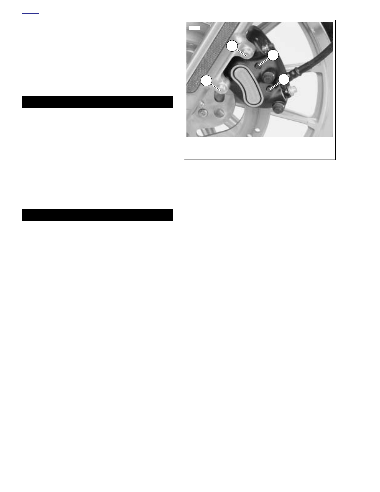
1. Short mounting bolt (12 pt/10 mm)
2. Long mounting bolt (12 pt/10 mm)
3. Pad pins (12 pt/0.25 in)
Figure 1-18. Front Brake Caliper
(Left Side Shown)
3
11WARNING1WARNING
After repairing the brake system, test brakes at low
speed. If brakes are not operating properly, testing at
high speeds can cause loss of control, which could
result in death or serious injury. (00289a)
17. Test brake system.
a. Turn ignition switch ON. Pump brake pedal to verify
operation of the brake lamp.
b. Test ride the motorcycle. If the brakes feel spongy,
bleed the system. See 1.7 BLEEDING BRAKES.
NOTE
Avoid making hard stops for the first 100 miles (160 km). This
allows the
discs.
new
pads to become conditioned to the brake
1-20 2006 Dyna: Maintenance
Page 23
HOME
12206
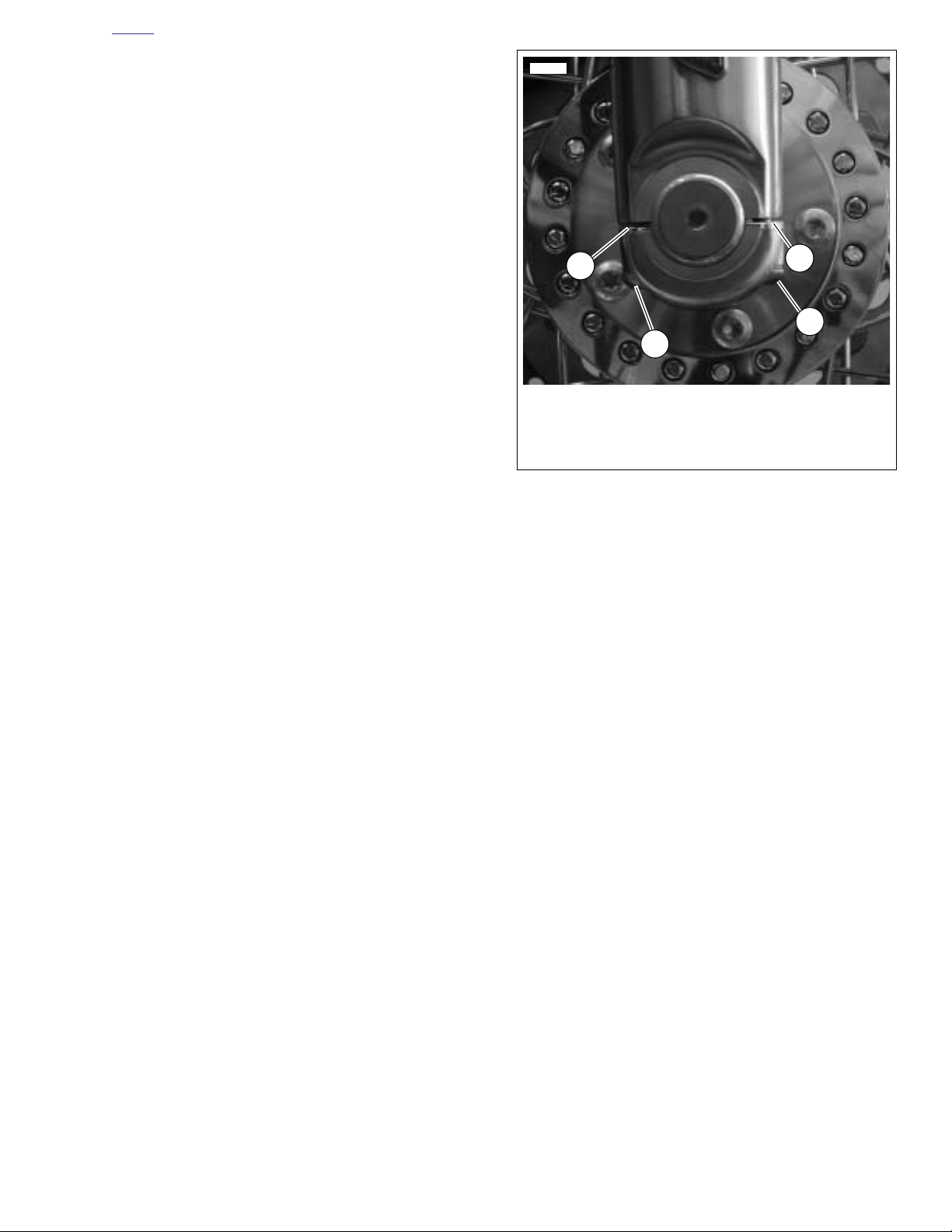
1. Cast in spacer
2. Rear axle cap fastener
3. Front axle cap fastener
4. gap
4
1
2
3
Front Brake Caliper
1. Remove the front master cylinder reservoir cap. As the
pistons are pushed back into the caliper, fluid level may
rise more than 1/8 in. (3.2 mm). You may have to remove
fluid to allow for this.
2. See Figure 1-18. Loosen, but do not remove, both pad
pins (3) (12 pt/0.25 in.).
3. Remove both caliper mounting bolts (1, 2) (metric).
Detach caliper from front forks and brake disc.
4. Pry the pads back to force all four caliper pistons into
their bores.
5. With the pistons retracted, remove the pad pins and
brake pads.
6. Inspect pad pins for grooving and wear. Measure the pad
pin diameter in an unworn area, and then in the area of
any grooving or wear. If wear is more than 0.015 in. (0.38
mm), replace both pins.
NOTES
See Figure 1-17. The front and rear brake calipers use
●
the same exact brake pad set.
The pad with two tabs (1), installs on the outboard side of
●
the caliper.
Figure 1-19. Axle cap
7. Install
8. Loosely install the pad pins until you hear an audible
9. Attach caliper to front fork.
new
pads into caliper. Curved portion of pad must
face rear of motorcycle.
click.
a. See Figure 1-18. Place caliper over brake disc with
bleeder valve facing upwards.
b. Loosely install long mounting bolt (2) (12 pt/10 mm)
into top hole on fork leg.
c. Install short mounting bolt (1) (12 pt/10 mm) into
bottom hole on fork leg. Tighten bottom mounting
bolt to 28-38 ft-lbs (38.0-51.5 Nm).
d. Final tighten the top mounting bolt to 28-38 ft-lbs
(38.0-51.5 Nm).
e. Final tighten both pad pins to 180-200
22.6 Nm).
f. See Figure 1-19. With cast in spacer (1) of axle cap
facing rear of vehicle, tighten rear axle cap fastener
(2) to 12 ft-lbs (16.3 Nm) while holding slider against
7/16 drill bit if necessary.
g. While holding slider against 7/16 drill bit if neces-
sary, tighten front axle cap fastener to 12 ft-lbs (16.3
Nm). Remove drill bit.
in-lbs
(20.3-
2006 Dyna: Maintenance 1-21
Page 24

HOME
11WARNING1WARNING
After servicing brakes and before moving motorcycle,
pump brakes to build brake system pressure. Insufficient
pressure can adversely affect brake performance, which
could result in death or serious injury. (00279a)
10. Pump brake hand lever to move pistons out until they
contact both brake pads. Verify piston location against
pads. If the front wheel is off the ground, rotate wheel to
check for excessive brake pad drag.
11. Check brake fluid level in master cylinder. Fill to proper
level if necessary using D.O.T. 4 BRAKE FLUID. Install
master cylinder reservoir cap. Tighten reservoir cap
screws to 6-8
in-lbs
(0.7-0.9 Nm).
11WARNING1WARNING
After repairing the brake system, test brakes at low
speed. If brakes are not operating properly, testing at
high speeds can cause loss of control, which could
result in death or serious injury. (00289a)
12. Test brake system.
a. Turn ignition switch ON. Pump brake hand lever to
verify operation of the brake lamp.
b. Test ride the motorcycle. If the brakes feel spongy,
bleed the system. See 1.7 BLEEDING BRAKES.
NOTE
Avoid making hard stops for the first 100 miles (160 km). This
allows the
discs.
new
pads to become conditioned to the brake
1-22 2006 Dyna: Maintenance
Page 25
HOME
o0250x0x
o0249x0x
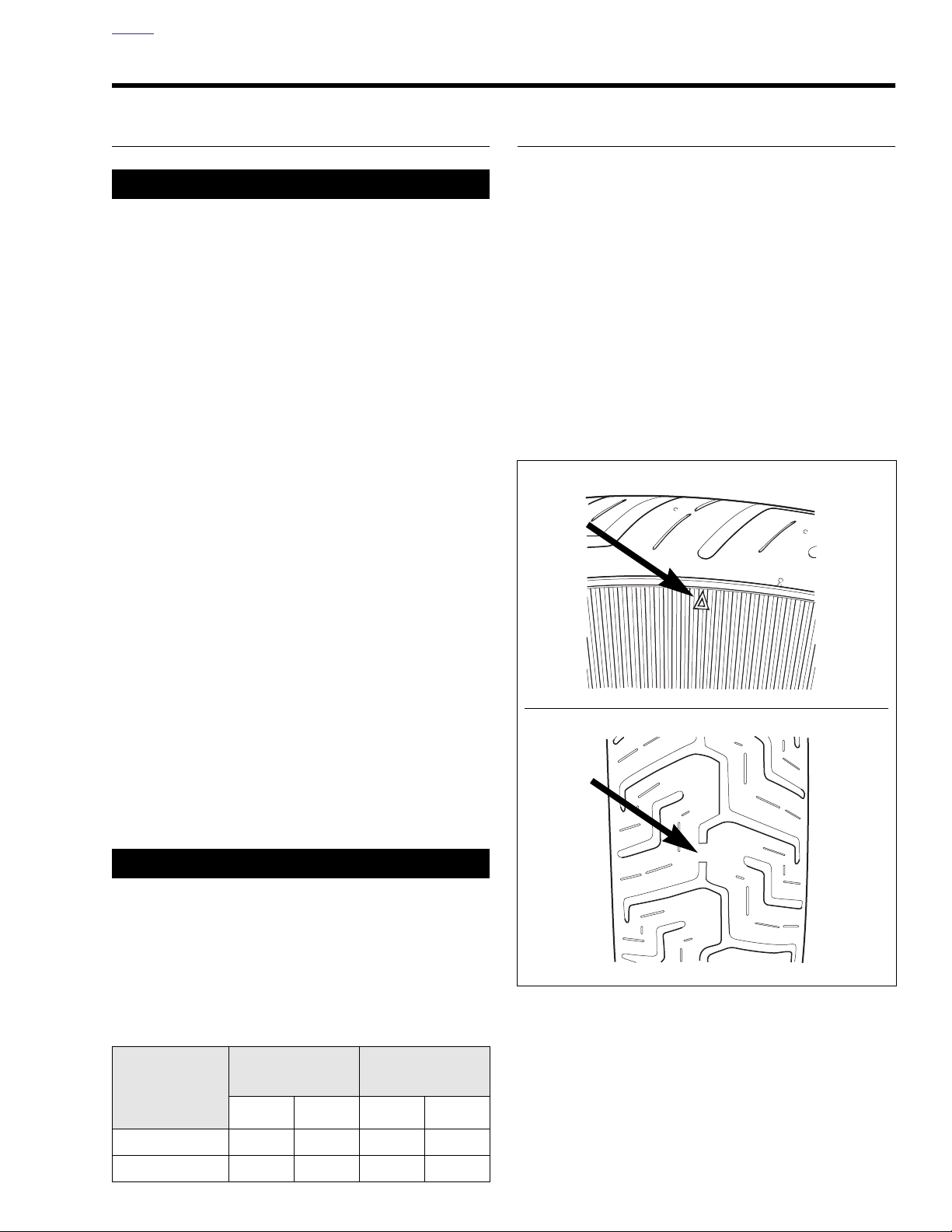
Sidewall
Tread
surface
TIRES AND WHEELS 1.9
TIRES
11WARNING1WARNING
Match tires, tubes, air valves and caps to the correct
wheel rim. Contact a Harley-Davidson dealer. Mismatching can result in damage to the tire bead, allow tire slippage on the rim or cause tire failure, which could result
in death or serious injury. (00023a)
Use only Harley-Davidson approved tires. Using non-
●
approved tires can adversely affect stability, which
could result in death or serious injury. (00024a)
Use inner tubes on laced (wire spoked) wheels.
●
Using tubeless tires on laced wheels can cause air
leaks, which could result in death or serious injury.
(00025a)
●
Inner tubes must not be used in radial tires and
radial tires must not be used on laced (wire spoked)
wheels.
●
Tubeless tires are used on all Harley-Davidson cast
and disc wheels.
●
Tire sizes are molded on the tire sidewall. Inner tube
sizes are printed on the tube.
TIRE REPLACEMENT
See Figure 1-20. Tread wear indicator bars appear on tire
tread surfaces when 1/32 inch (0.8 mm) or less tire tread
remains. Arrows on tire sidewalls pinpoint location of wear
bar indicators. Always remove tires from service before they
reach the tread wear indicator bars, indicating 1/32 inch (0.8
mm) tread pattern depth remaining.
New tires are needed if any of the following conditions exist.
● Tire wear indicator bars become visible on the tread sur-
faces.
● Tire cords or fabric become visible through cracked side-
walls, snags or deep cuts.
● A bump, bulge or split in the tire is found.
● Puncture, cut or other damage to the tire that cannot be
repaired.
Check tire pressure and tread:
●
As part of the pre-ride inspection.
●
At every scheduled service interval.
1. Inspect each tire for punctures, cuts, and breaks.
2. Inspect each tire for wear. Replace tires before they
reach the tread wear indicator bars.
NOTE
Missing indicator wear bars represent less than 1/32 in.
(0.8 mm) tread pattern depth remaining.
11WARNING1WARNING
Do not inflate tire beyond maximum pressure as specified on sidewall. Over inflated tires can blow out, which
could result in death or serious injury. (00027a)
3. Check for proper front and rear tire pressures when tires
are cold. Compare results against Tab le 1-5.
Table 1-5. Tire Pressures
ALL MODELS
DUNLOP TIRES
ONLY
SOLO RIDER
PSI kPA PSI kPA
RIDER & ONE
PASSENGER
Figure 1-20. Tread Wear Indicators
Front 30 207 30 207
Rear 36 248 40 276
2006 Dyna: Maintenance 1-23
Page 26

HOME
WHEEL BEARINGS
Service wheel bearings:
● Inspect any time the wheels are removed.
● Replace when bearings exceed end play service wear
limit of 0.002 in. (0.051 mm).
Check wheel bearings and axle spacers for wear and corrosion. Excessive play or roughness indicates worn bearings.
Replace bearings in sets only. See 2.6 SEALED WHEEL
BEARINGS.
WHEEL SPOKES
1. Raise motorcycle wheel off the ground.
11WARNING1WARNING
Spokes that are too tight can draw nipples through the
rim or distort hub flanges. Spokes that are too loose can
continue to loosen when put in service. Either condition
can adversely affect stability and handling, which could
result in death or serious injury. (00286a)
CAUTION
If nipples require more than one full turn to tighten
spoke, remove tire to check that spoke is not protruding
far enough to damage tube.
2. Lightly tap each spoke with a spoke wrench. Loose
spokes will sound dull and must be tightened. Tighten
spokes to 55-65 in-lbs (6.2-7.3 Nm). If more than a few
spokes are loose, true the entire wheel following procedure under 2.10 TRUING LACED WHEEL.
1-24 2006 Dyna: Maintenance
Page 27

HOME
PRIMARY CHAIN 1.10
GENERAL
NOTE
The 2006 Dyna models have an automatic chain tensioner.
See 6.3 DRIVE COMPONENTS for primary chain procedures.
2006 Dyna: Maintenance 1-25
Page 28
HOME
PRIMARY CHAINCASE LUBRICANT 1.11
CHANGING LUBRICANT
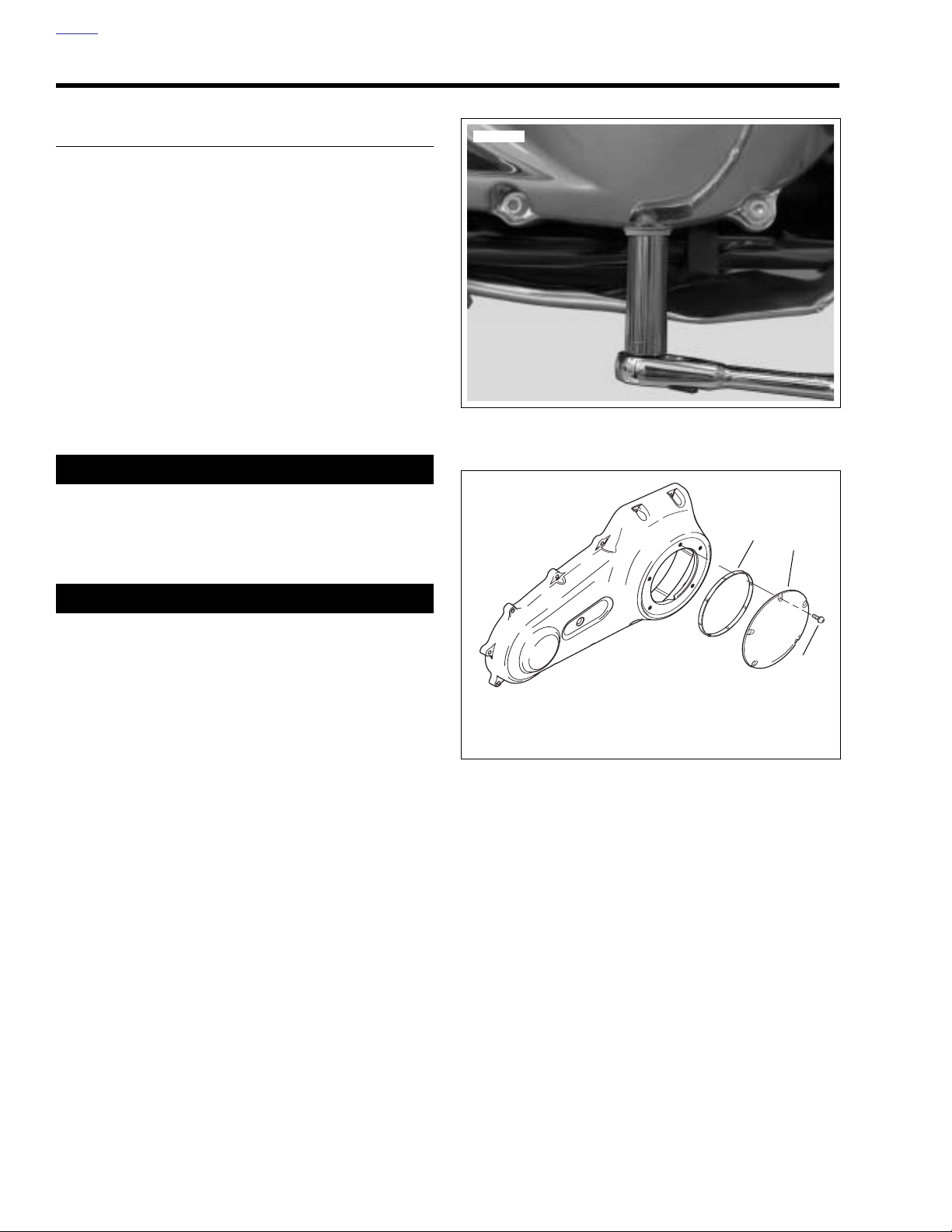
1. See Figure 1-21. Remove drain plug at bottom of inner
primary chaincase. Drain lubricant into suitable container.
2. Clean drain plug. If plug has accumulated a lot of debris,
inspect the condition of chaincase components.
3. Install new o-ring on drain plug.
4. Install drain plug back into primary chaincase cover.
Tighten plug to 36-60 in-lbs (4.1-6.8 Nm).
5. See Figure 1-22. Remove five TORX screws with captive
washers (1) to detach clutch inspection cover (2) from
primary chaincase cover.
6. Remove the gasket. Wipe oil from groove in chaincase
cover and mounting surface.
11WARNING1WARNING
Check that no lubricant gets on rear tire, wheel or brakes
when changing fluid. Traction can be adversely affected,
which could result in loss of control of the motorcycle
and death or serious injury. (00047a)
12207
Figure 1-21. Removing Chaincase Drain Plug
d0161b1x
3
2
CAUTION
Do not overfill the primary chaincase with lubricant.
Overfilling can cause rough clutch engagement, incomplete disengagement, clutch drag and/or difficulty in finding neutral at engine idle. (00199b)
7. See Figure 1-22. Pour 32 oz (0.95 liter) of primary chain-
case lubricant in through the clutch inspection cover
opening.
NOTE
● Use only genuine Harley-Davidson FORMULA+ TRANS-
MISSION AND PRIMARY CHAINCASE LUBRICANT,
Part No. 99851-05 (quart).
● If new clutch discs are being installed, or if the lubricant
has been wiped from serviceable discs, submerge the
discs in FORMULA+ PRIMARY CHAINCASE LUBRICANT for a minimum of five minutes before installation.
1
1. TORX screw with captive washer (5)
2. Clutch inspection cover
3. Seal
Figure 1-22. Clutch Cover
1-26 2006 Dyna: Maintenance
Page 29
HOME
2
3
5
4
d0161c1x
1
8. Install clutch inspection cover and seal as follows:
a. Thoroughly wipe all lubricant from cover mounting
surface and groove in chaincase.
b. See Figure 1-22. Position seal (3) in groove in pri-
mary chaincase cover and press each of the nubs
on seal into the groove. The nubs will retain seal in
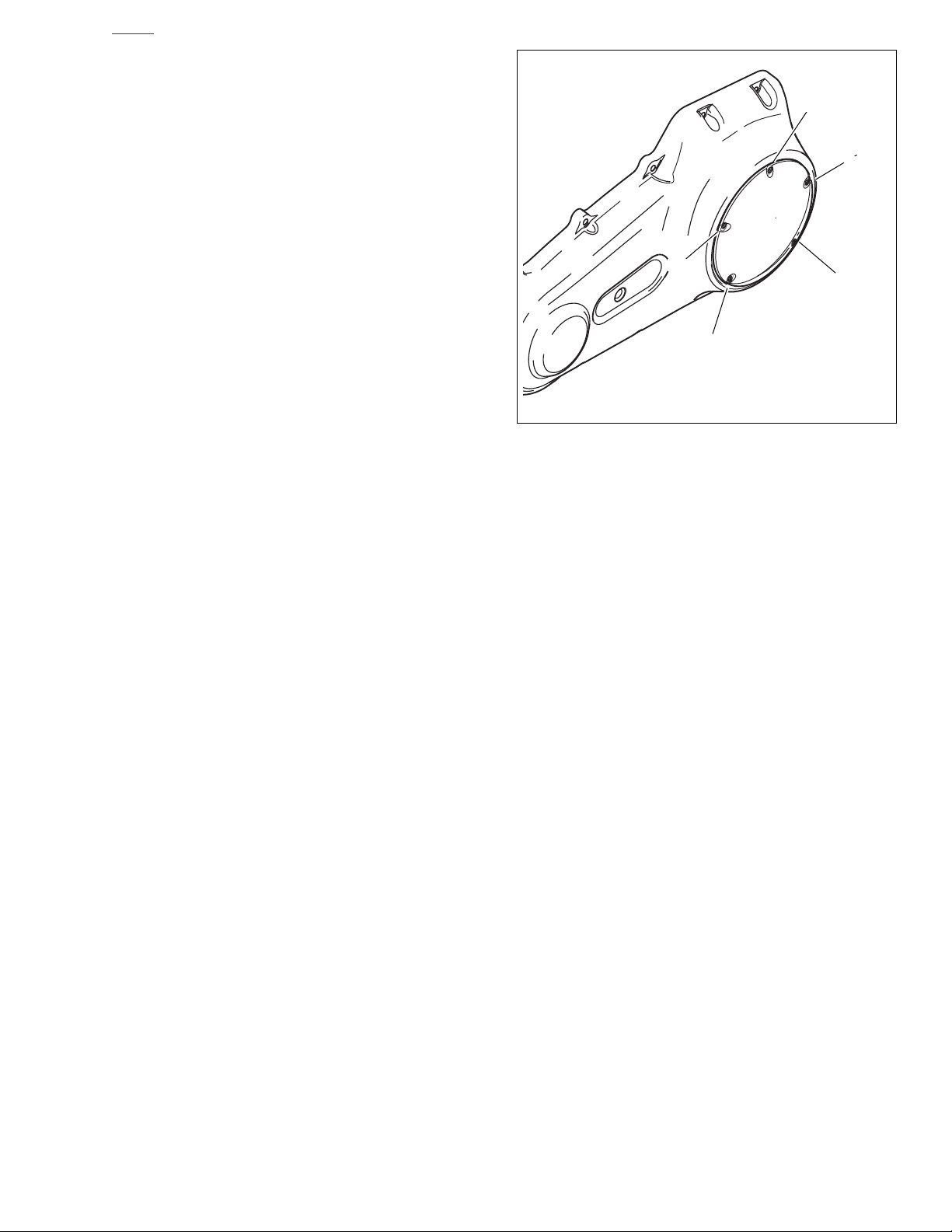
position.
c. See Figure 1-23. Insert screw (with captive washer)
through clutch inspection cover and carefully thread
it into the top cover screw hole.
d. Start the remaining four screws (with captive wash-
ers).
e. Alternately tighten screws to 84-108 in-lbs (9.5-12.2
Nm) following torque sequence shown in Figure 1-
23.
Figure 1-23. Clutch Cover Torque Sequence
2006 Dyna: Maintenance 1-27
Page 30
HOME
CLUTCH 1.12
ADJUSTMENT
CAUTION
Perform the clutch adjustment with the motorcycle at
room temperature. The clearance at the adjuster screw
will increase as the powertrain temperature increases. If
adjuster screw is adjusted with powertrain hot, clearance
at push rod bearing could be insufficient with powertrain
cold and clutch slippage could occur.
1. Stand motorcycle upright and level.
2. Remove five TORX screws with captive washers to
detach clutch inspection cover from primary chaincase
cover.
3. Remove and discard clutch inspection cover seal.
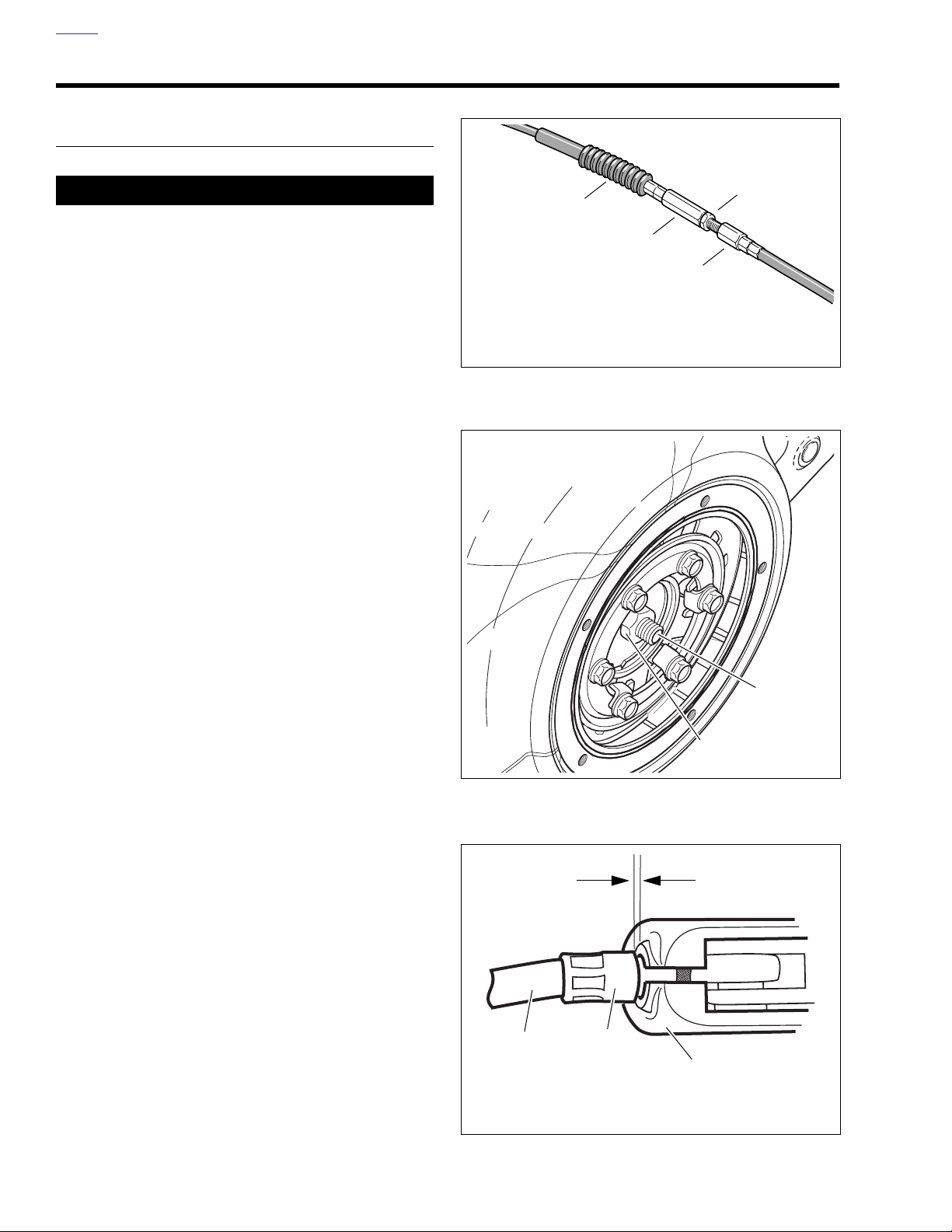
4. See Figure 1-24. Add freeplay to cable.
a. Slide rubber boot (1) off cable adjuster.
b. Holding cable adjuster (2) with 1/2 in. wrench,
loosen jam nut (3) using a 9/16 in. wrench.
d0599x1x
3
1
2
4
1. Rubber boot
2. Cable adjuster
3. Jam nut
4. Cable end
Figure 1-24. Clutch Cable Adjuster
1. Locknut
2. Clutch adjuster screw
c. Turn cable adjuster (2) until there is a large amount
of freeplay at clutch hand lever.
5. See Figure 1-25. Loosen locknut (1) on clutch adjuster
screw (2). To take up all freeplay, turn screw inward
(clockwise) until lightly seated. Activate the clutch lever
to verify the balls are seated in the ramps.
6. Back out adjusting screw (counterclockwise) 1/2 to 1 full
turn. Tighten jam nut to 72-120 in-lbs (8.1-13.6 Nm),
while holding adjusting screw with an Allen wrench.
7. Squeeze clutch lever to maximum limit three times, to set
ball and ramp release mechanism.
8. Check freeplay.
a. Turn cable adjuster away from jam nut until slack is
eliminated at hand lever.
b. See Figure 1-26. Pull clutch cable ferrule (2) away
from clutch lever bracket (3) to check freeplay. Turn
cable adjuster as necessary to obtain 1/16-1/8 in.
(1.6-3.2 mm) freeplay between end of cable ferrule
and clutch lever bracket.
9. Hold adjuster with 1/2 in. wrench. Using 9/16 in. wrench,
tighten jam nut against cable adjuster. Cover cable
adjuster mechanism with rubber boot.
Figure 1-25. Clutch Adjuster Screw
d0382a1x
1
1. Clutch cable
2. Cable ferrule
3. Clutch lever bracket
2
1
1/16-1/8 in.
(1.6-3.2 mm)
3
2
d0383c1x
1-28 2006 Dyna: Maintenance
Figure 1-26. Clutch Hand Lever
Page 31

HOME
10. Install clutch inspection cover and seal. Install seal as follows:
a. Thoroughly wipe all lubricant from cover mounting
surface and groove in chaincase.
b. See Figure 1-22. Position seal (3) in groove in pri-
mary chaincase cover and press each of the nubs
on seal into the groove. The nubs will retain seal in
position.
c. See Figure 1-23. Insert screw (with captive washer)
through clutch inspection cover and carefully thread
it into the top cover screw hole.
d. Start the remaining four screws (with captive wash-
ers).
e. Alternately tighten screws to 84-108 in-lbs (9.5-12.2
Nm) following torque sequence shown in Figure 1-
23.
2006 Dyna: Maintenance 1-29
Page 32
HOME
TRANSMISSION LUBRICANT 1.13
CHANGING LUBRICANT
11767
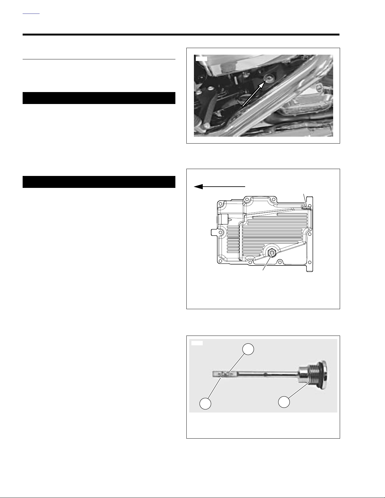
1. See Figure 1-27. Remove transmission filler plug.
2. See Figure 1-28. Remove transmission drain plug (2)
and drain lubricant into a suitable container.
CAUTION
Do not over-tighten drain plug. Doing so could result in a
lubricant leak. (00200a)
3. Install drain plug.
a. Inspect O-ring on drain plug for tears or damage.
Replace as required. Wipe any foreign material from
plug.
b. Install O-ring and drain plug. Tighten to 14-21 ft-lbs
(19.0-28.5 Nm). Do not over-tighten.
11WARNING1WARNING
Check that no lubricant gets on rear tire, wheel or brakes
when changing fluid. Traction can be adversely affected,
which could result in loss of control of the motorcycle
and death or serious injury. (00047a)
4. Fill the transmission with 32 oz. (0.95 liter) of GENUINE
Harley-Davidson FORMULA+ TRANSMISSION AND
PRIMARY CHAINCASE LUBRICANT, Part No. 99851-05
(quart).
5. Check the transmission lubricant level with engine turned
off and motorcycle resting on jiffy stand on level surface.
6. See Figure 1-27. Unscrew and remove transmission
lubricant filler cap with attached dipstick. Wipe dipstick
clean.
7. See Figure 1-29. Reinsert dipstick into transmission fill
hole. Bottom edge of threaded section of dipstick should
rest on lip of fill hole. Do not screw filler cap in.
8. Remove filler cap and check lubricant level on dipstick. If
necessary, add lubricant and recheck until level is
between lower mark (1) and upper mark (2) on dipstick.
9. Install filler plug/dipstick and tighten to 25-75 in-lbs (2.8-
8.5 Nm).
Figure 1-27. Transmission Lubricant Filler Plug/Dipstick
Front of motorcycle
d0442x3x
1
2
1. Engine oil drain plug
2. Transmission drain plug and o-ring @ 14-21 ft-lbs
(19.0-28.5 Nm)
Figure 1-28. Oil Pan
11766
2
1-30 2006 Dyna: Maintenance
1
1. Lower mark (add lubricant)
2. Upper mark (full)
3. Bottom edge of threaded section
Figure 1-29. Filler Plug/Dipstick
3
Page 33
HOME
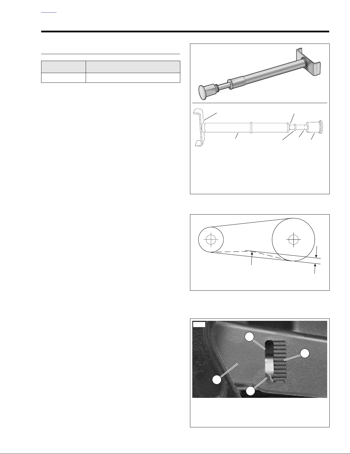
d0696x1x
1
1. Belt tension gauge
2. Belt cradle
3. 0 ft-lbs (0 kg) mark
4. O-ring
5. 10 lbs (4.5 kg) mark
6. Knob
2
5
4
6
3
d0600a1x
d0164x1x
A
10 lbs (4.5 kg)
of force
5/16-3/8 in.
(7.9-9.5 mm)
8844
1. Debris deflector
2. Belt deflection viewing window
3. Drive belt deflection graduations
4. Drive belt
1
2
3
4
REAR BELT DEFLECTION 1.14
INSPECTION
PART NO. SPECIALTY TOOL
HD-35381 Belt tension gauge
Check rear belt deflection:
● As part of the pre-ride inspection.
● At every scheduled service interval.
When checking belt deflection:
● Set belt tension at tightest point in belt.
● Measure belt deflection with motorcycle cold and the
approximate weight of the owner on motorcycle.
1. See Figure 1-30. Obtain BELT TENSION GAUGE (HD-
35381).
NOTE
Customers may purchase gauge from an authorized HarleyDavidson dealer.
2. To use the belt tension gauge:
a. Slide O-ring (4) toward 0 lbs (0 kg) mark (3).
b. Fit belt cradle (2) against bottom of drive belt half-
way between drive pulleys (point A in Figure 1-31.).
c. Press upward on knob (6) until O-ring slides down to
10 lbs (4.5 kg) mark (5).
d. See Figure 1-32. Measure belt deflection as viewed
through deflection viewing window (2) while holding
gauge steady. Deflection graduations (3) are 1/8 in.
(3.2 mm) apart.
Figure 1-30. Belt Tension Gauge (Part No. HD-35381)
10
0
Figure 1-31. Checking Belt Deflection
Figure 1-32. Belt Deflection Window
2006 Dyna: Maintenance 1-31
Page 34
HOME
3. See Figure 1-31. Check that the drive belt bottom strand
deflects 5/16-3/8 in. (7.9-9.5 mm) while applying 10 lbs
(4.5 kg) of force upward at point A.
4. Measure belt deflection several times, each time with belt
moved (by rotating rear wheel) to a different position on
sprockets.
NOTE
Do not rely on “feel” for the proper deflection as this typically
results in belts which are under tensioned. Always use H-D
BELT TENSION GAUGE (Part No. HD-35381) to determine
the 10 lb. (4.5 Kg) deflection force. Loose belts will fail due to
“ratcheting” (jumping a tooth) with resultant tensile cord
crimping and breakage.
1
2
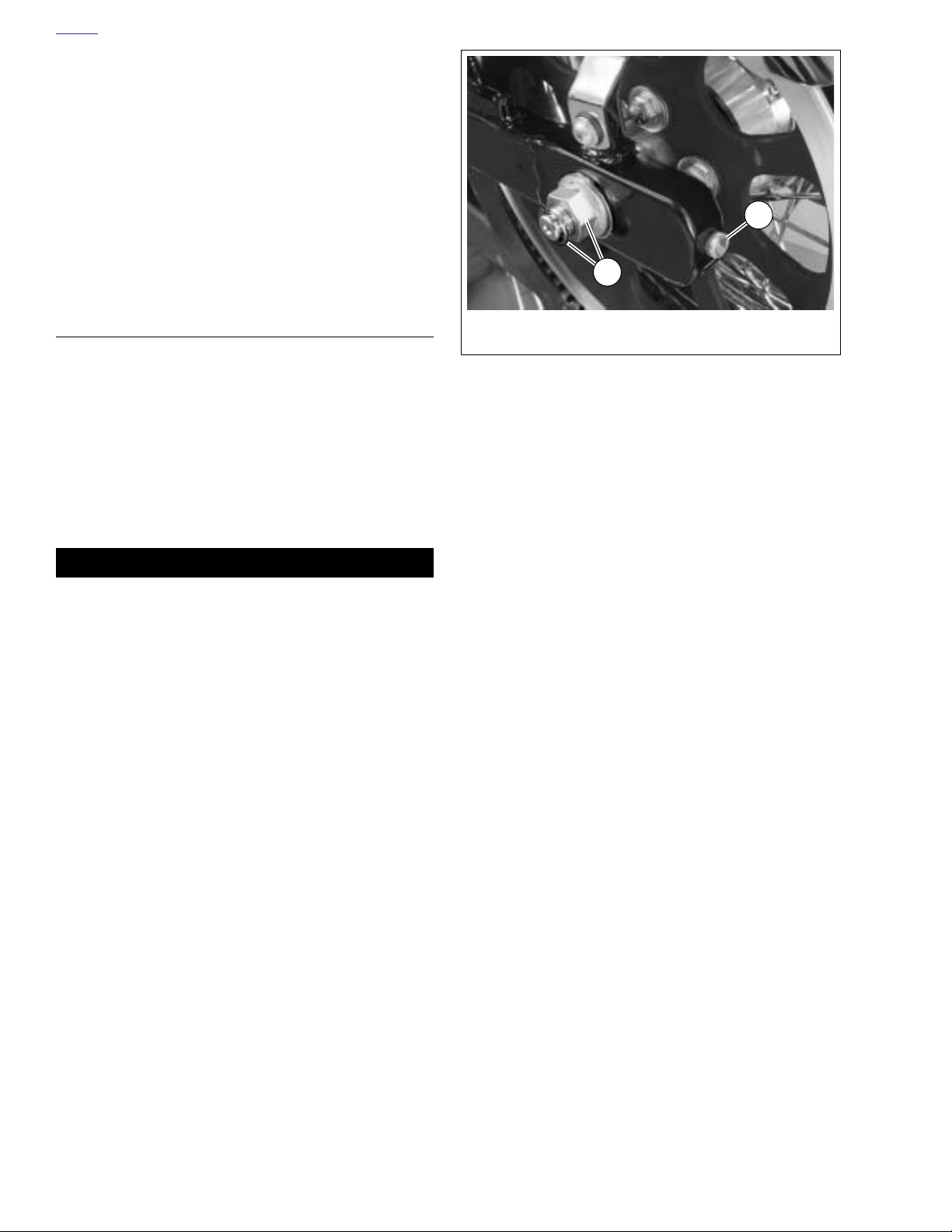
ADJUSTMENT
If belt adjustment is necessary, perform the following procedure:
1. See Figure 1-33. Remove spring clip (1) and loosen axle
nut (2).
2. Adjust belt tension by turning the axle adjusters (3) an
equal number of turns to keep the wheel aligned until the
specification in step 3 under ADJUSTMENT above is
achieved.
3. Verify rear wheel alignment. See 2.13 VEHICLE ALIGN-
MENT.
11WARNING1WARNING
Check wheel bearing end play after tightening axle nut to
specified torque. Excessive end play can adversely affect
stability and handling. Insufficient end play can cause
bearing seizure. Either condition can cause loss of control, which could result in death or serious injury.
(00285a)
4. Tighten axle nut (2) to 60 ft-lbs (81.3 Nm).
5. Check to see if the spring clip (1) can be installed. If
required, tighten nut just enough to align axle hole and
nut slots, but do not exceed 65 ft-lbs (88.1 Nm).
1. Axle adjuster
2. Axle nut and spring clip
Figure 1-33. Axle Adjusters
1-32 2006 Dyna: Maintenance
Page 35
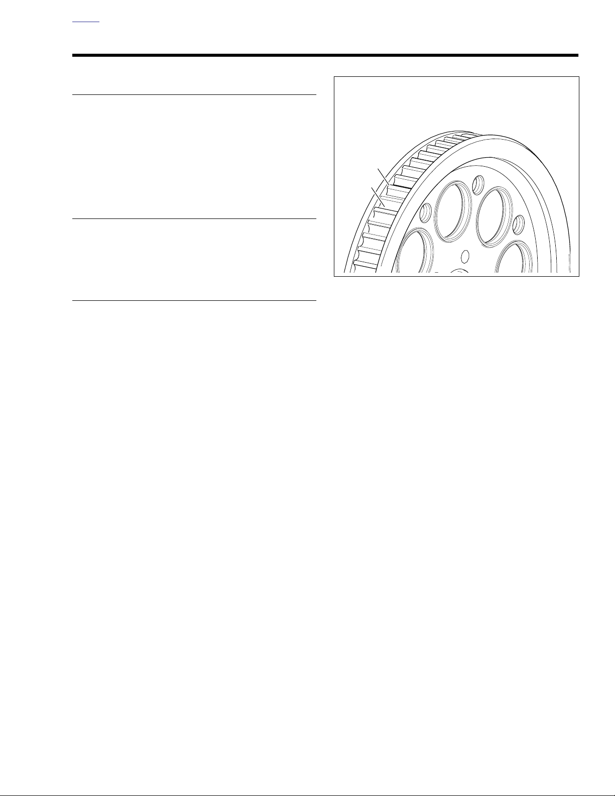
HOME
1. Tooth
2. Groove
1
2
d0416x1x
REAR BELT AND SPROCKETS 1.15
GENERAL
NOTE
When a drive belt is replaced for any reason other than stone
damage, it is recommended that the transmission and rear
sprockets also be replaced to increase the longevity of the
new drive belt. In the case of stone damage, inspect sprockets for damage and replace as required.
CLEANING
Keep dirt, grease, oil, and debris off the belt and sprockets.
Clean the belt with a rag which is slightly damp with a light
cleaning agent.
INSPECTION
Sprockets
NOTE
If chrome chips or gouges to rear sprocket are large enough
to be harmful, they will leave a pattern on the belt face.
1. See Figure 1-34. Inspect each tooth (1) of rear sprocket
for:
a. Major tooth damage.
b. Large chrome chips with sharp edges.
c. Gouges caused by hard objects.
d. Excessive loss of chrome plating (see step 2).
2. To check if chrome plating has worn off, drag a scribe or
sharp knife point across the bottom of a groove (2)
(between two teeth) with medium pressure.
a. If scribe or knife point slides across groove without
digging in or leaving a visible mark, chrome plating
is still good.
b. If scribe or knife points digs in and leaves a visible
mark, it is cutting the bare aluminum. A knife point
will not penetrate the chrome plating.
3. Replace rear sprocket if major tooth damage or loss of
chrome exists.
Figure 1-34. Rear Sprocket
Rear Belt
See Figure 1-35. Inspect drive belt for:
● Cuts or unusual wear patterns.
● Outside edge bevelling (8). Some bevelling is common,
but it indicates that sprockets are misaligned.
● Outside ribbed surface for signs of stone puncture (7). If
cracks/damage exists near edge of belt, replace belt
immediately. Damage to center of belt will require belt
replacement eventually, but when cracks extend to edge
of belt, belt failure is imminent.
● Inside (toothed portion) of belt for exposed tensile cords
(normally covered by nylon layer and polyethylene layer).
This condition will result in belt failure and indicates worn
transmission sprocket teeth. Replace belt and transmission sprocket.
● Signs of puncture or cracking at the base of the belt
teeth. Replace belt if either condition exists.
● Replace belt if conditions 2, 3, 6 or 7 (on edge of belt)
exist.
NOTE
Condition 1 may develop into 2 or 3 over time. Condition 1 is
not grounds for replacing the belt, but it should be watched
closely before condition 2 develops which will require belt
replacement.
2006 Dyna: Maintenance 1-33
Page 36
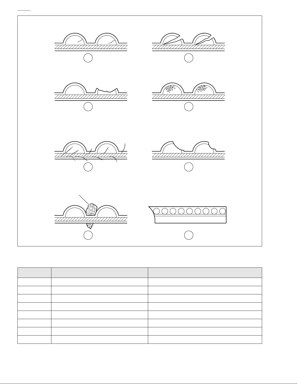
HOME
d0598x1x
1 2
3 4
5 6
Stone
Cross-section shown
7 8
Figure 1-35. Drive Belt Wear Patterns
Table 1-6. Drive Belt Wear Analysis
PATTERN CONDITION REQUIRED ACTION
1 Internal tooth cracks (hairline) OK to run, but monitor condition
2 External tooth cracks Replace belt
3 Missing teeth Replace belt
4 Chipping (not serious) OK to run, but monitor condition
Sprocket
side of belt
5 Fuzzy edge cord OK to run, but monitor condition
6 Hook wear Replace belt
7 Stone damage Replace belt if damage is on the edge
8Bevel wear (outboard edge only) OK to run, but monitor condition
1-34 2006 Dyna: Maintenance
Page 37
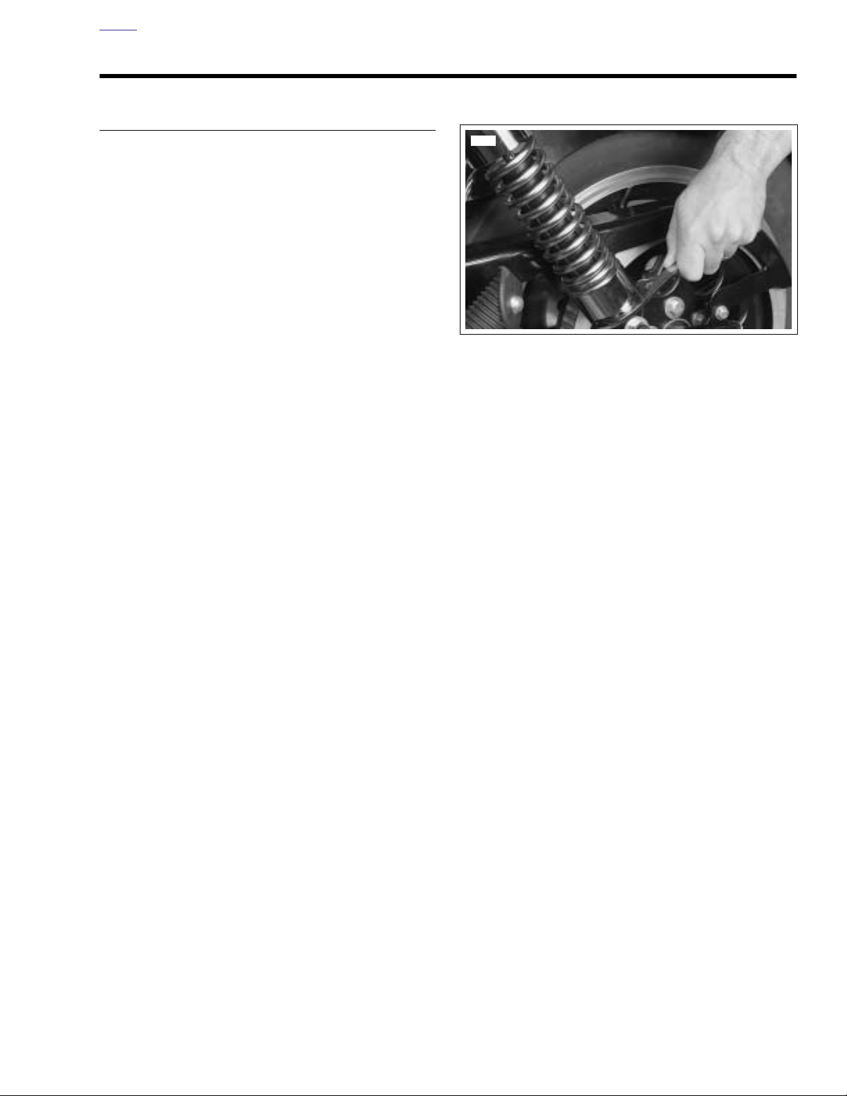
HOME
3587
SUSPENSION ADJUSTMENTS 1.16
ALL MODELS
The rear shock absorber springs can be adjusted to five positions to compensate for various loads.
● For heavy loads, the springs should be compressed.
● For lighter loads the springs should be extended.
See Figure 1-36. To adjust the rear shock absorber, turn
spring adjusting cam to desired position with spanner
wrench. Both spring adjusting cams must be adjusted to the
same position. When returning to off-cam position, cams
should be backed off in opposite direction.
Figure 1-36. Rear Shock Absorber Spring Adjustment
2006 Dyna: Maintenance 1-35
Page 38
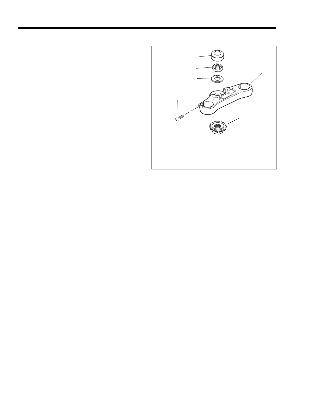
HOME
STEERING HEAD BEARINGS 1.17
ADJUSTMENT
Bearing Adjustment (Fall-Away)
1. Support motorcycle in an upright position so the front
end is completely suspended and the vehicle is level.
2. Remove all accessory weight, such as a windshield, that
may influence the way the front end swings. If clutch
cable is routed so it pulls the front end one way or the
other, disconnect it.
3. Place a suitable marking material, such as masking tape,
over the fender tip.
4. Install a pointer so the base is stationary on the floor and
the pointer indicates the center of the fender. The front
end should be straight ahead, however the balance point
may be slightly off center.
5. Check steering head bearing tension.
a. Tap the fender on one side until the front end begins
to “fall-away” by itself. Label this point on the mark-
ing material.
b. Repeat the previous step in the other direction.
c. Measure distance between marks.
6. The distance between the “fall-away” marks must be 2.0-
4.0 in. (50.8-101.6 mm).
NOTE
If distance measured is 2.0-4.0 in. (50.8-101.6 mm) no bearing adjustment is needed.
NOTE
If distance measured is outside the range given in step 7
bearing adjustment is needed. See Figure 1-37. To access
the adjuster nut (1) the upper triple clamp (2) must be moved
upward.
7. With HUBCAP REMOVER AND INSTALLER (HD-
41494) unscrew and remove stem cap (3).
8. Bend down the fork stem lock washer (4) tab, and loosen
fork stem nut (5).
9. Loosen upper triple clamp pinch bolts and move upper
triple clamp up enough to expose star nut
10. Tighten one pinch bolt enough to hold upper triple clamp
in the raised position.
3
5
2
4
6
1
1. Star nut
2. Upper triple clamp
3. Stem cap
4. Lock washer
5. Stem nut
Figure 1-37. Steering Head Components
11. Tighten or loosen the fork adjuster nut until the measurement is within limits.
a. If the distance is more than 4.0 in. (101.6 mm), turn
the adjuster nut counter clockwise to loosen.
b. If the distance is less than 2.0 in. (50.8 mm), turn the
adjuster nut clockwise to tighten.
12. Lower upper triple clamp and tighten stem nut to 45-55
ft-lbs.
13. Check fall-away. If it is 2.0-4.0 in. (50.8-101.6 mm),
tighten upper triple clamp pinch bolts to 30-35 ft-lbs
(40.7-47.5 Nm).
14. Repeat the “fall-away” procedure to be sure the adjustment is correct.
15. Bend lock tab on lock washer against stem nut and
install stem cap.
16. Install and adjust clutch cable.
17. Test ride motorcycle.
6. Pinch bolt (2)
1-36 2006 Dyna: Maintenance
LUBRICATION
Use SPECIAL PURPOSE GREASE (Part No. 99857-97)
every 30,000 mile (48,280 km) service interval. See 2.19
STEERING HEAD for steering head bearing lubrication.
Page 39

HOME
FRONT FORK OIL 1.18
REPLACING FORK OIL
NOTE
Fork assemblies must be removed to drain fork oil. See 2.18
FRONT FORK.
2006 Dyna: Maintenance 1-37
Page 40
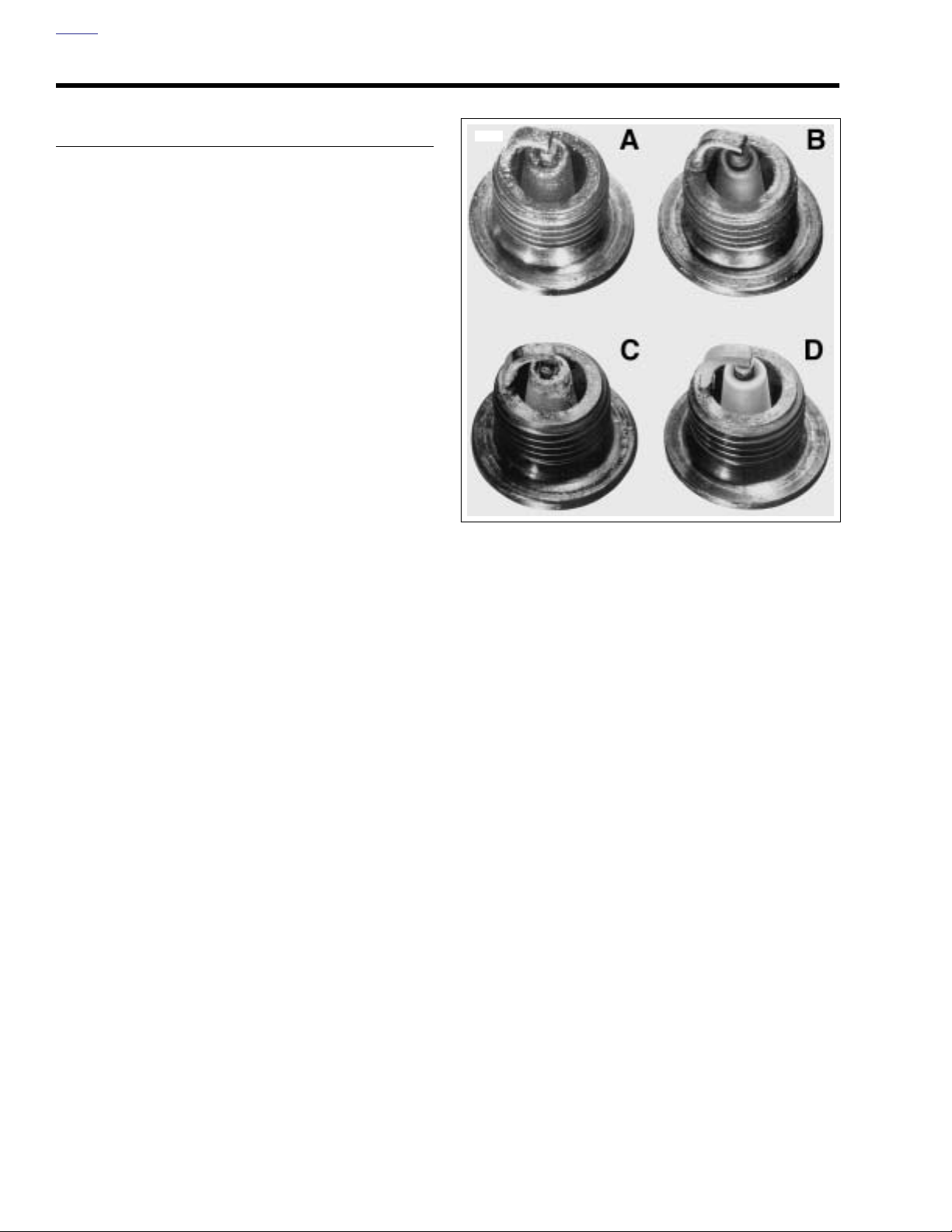
HOME
SPARK PLUGS 1.19
INSPECTION
1. After the engine has cooled to room temperature, disconnect cables from both spark plugs.
2. Remove spark plugs. If a plug has eroded electrodes,
heavy deposits or a cracked insulator, discard it.
3. See Figure 1-38. Compare your observations of the plug
deposits with the descriptions provided below.
a. A wet, black and shiny deposit on plug base, elec-
trodes and ceramic insulator tip indicates an oil
fouled plug. The condition may be caused by one or
more of the following: worn pistons, worn piston
rings, worn valves, worn valve guides, worn valve
seals, a weak battery or a faulty ignition system.
b. A dry, fluffy or sooty black deposit indicates an air-
fuel mixture that is too rich, engine idling for excessive periods of time.
c. A light brown, glassy deposit indicates an over-
heated plug. This condition may be accompanied by
cracks in the insulator or by erosion of the electrodes and is caused by an air-fuel mixture that is
too lean, a hot-running engine, valves not seating or
improper ignition timing. The glassy deposit on the
spark plug is a conductor when hot and may cause
high-speed misfiring. A plug with eroded electrodes,
heavy deposits or a cracked insulator must be
replaced.
d. A plug with a white, yellow, tan or rusty brown pow-
dery deposit indicates balanced combustion. Clean
off spark plug deposits at regular intervals.
4. If the plugs require cleaning between tune-ups, proceed
as follows:
a. Degrease firing end of spark plug using ELECTRI-
CAL CONTACT CLEANER. Dry plug with compressed air.
b. Use a thin file to flatten spark plug electrodes. A
spark plug with sharp edges on its electrodes
requires 25-40% less firing voltage than one with
rounded edges.
c. If the plugs cannot be cleaned, replace with No.
6R12 spark plugs.
4636
Figure 1-38. Typical Spark Plug Deposits
gauge is felt when passing it between electrodes. Proper
gap measurement is 0.038-0.043 in. (0.97-1.09 mm).
6. Check condition of threads on cylinder head and plug. If
necessary to remove deposits, apply penetrating oil and
clean out with a thread chaser.
7. Apply LOCTITE ANTI-SEIZE to plugs. Install and tighten
to 12-18 ft-lbs (16.3-24.4 Nm).
8. Connect spark plug cables. Rear cylinder plug cable
attaches to top coil terminal. Verify that cables are
securely connected to coil and spark plugs.
5. Check electrode gap with a wire-type feeler gauge. Bend
the outside of the electrode so only a slight drag on the
1-38 2006 Dyna: Maintenance
Page 41
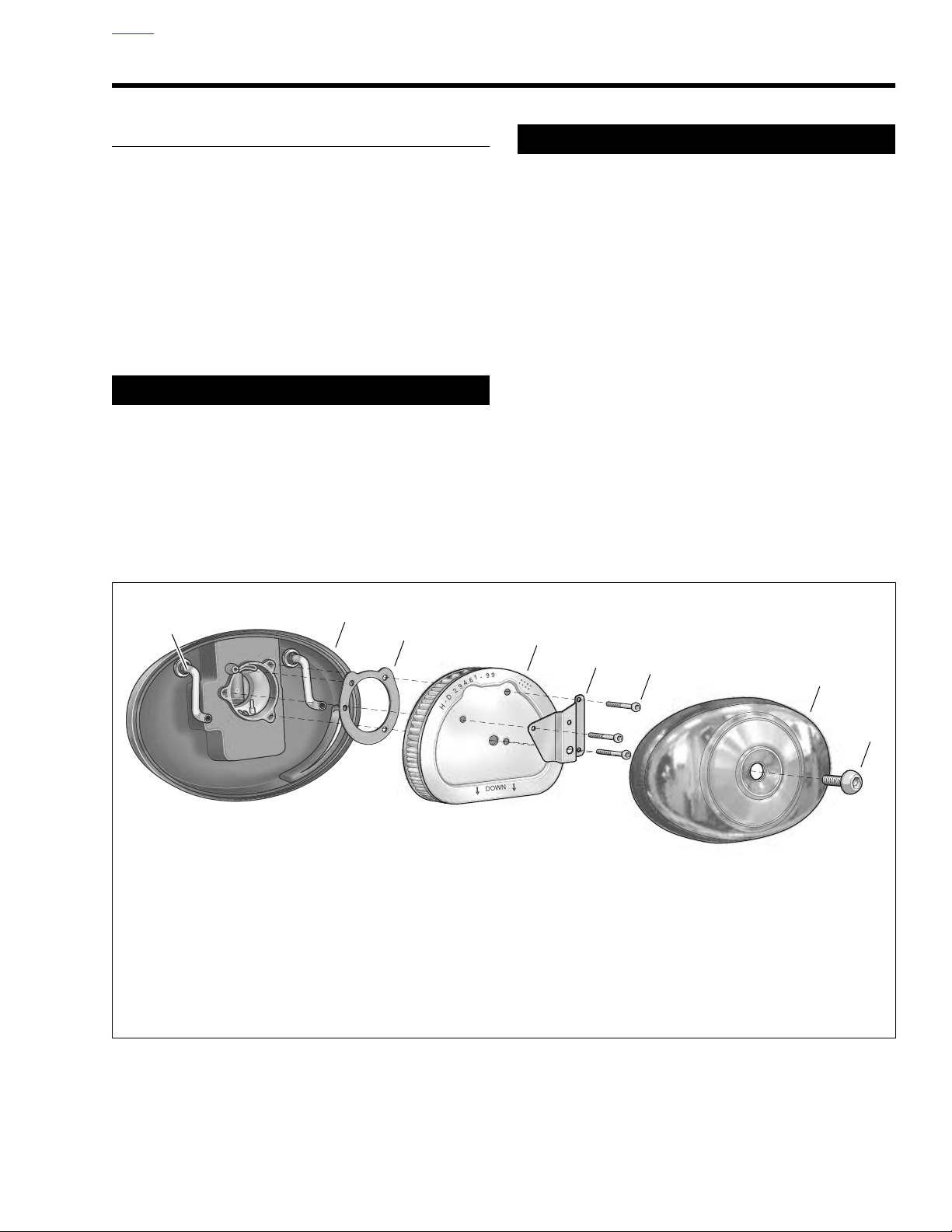
HOME
AIR CLEANER FILTER 1.20
REMOVAL
1. See Figure 1-39. Remove screw (1) and air cleaner
cover (2).
2. Remove three TORX screws (3) and bracket (4) from filter element (5).
3. Gently pull both rubber breather tubes (8) from the back
of the element. Remove filter element and gasket (6).
4. Replace the filter element if damaged or if filter media
cannot be adequately cleaned.
11WARNING1WARNING
Do not use gasoline or solvents to clean filter element.
Flammable cleaning agents can cause an intake system
fire, which could result in death or serious injury.
(00101a)
5. Gently pull the breather tubes from the breather bolts on
the backplate.
11WARNING1WARNING
Compressed air can pierce the skin and flying debris
from compressed air could cause serious eye injury.
Wear safety glasses when working with compressed air.
Never use your hand to check for air leaks or to determine air flow rates. (00061a)
6. Clean filter element.
a. Wash the paper/wire mesh air filter element and
breather tubes in lukewarm water with a mild detergent. Do not strike filter element on a hard surface to
dislodge dirt.
b. Allow filter to either air dry or blow it dry, from the
inside, with low pressure air. Do NOT use air cleaner
filter oil on the Harley-Davidson paper/wire mesh air
filter element.
c. Hold the filter element up to a strong light source. If
light is uniformly visible through the element, it is
sufficiently clean.
7. Inspect seal ring on cover for cracks or tears. Verify that it
seals tightly to backplate. Replace as required.
d0089x1x
7
8
1. Screw @ 36-60 in-lbs (4.1-6.8 Nm)
2. Air cleaner cover
3. T27 TORX screw (3) @ 20-40 in-lbs (2.3-4.5 Nm)
4. Bracket
5. Filter element
6. Gasket
7. Backplate
8. Breather hose (2)
6
5
4
3
2
1
Figure 1-39. Air Cleaner Assembly
2006 Dyna: Maintenance 1-39
Page 42
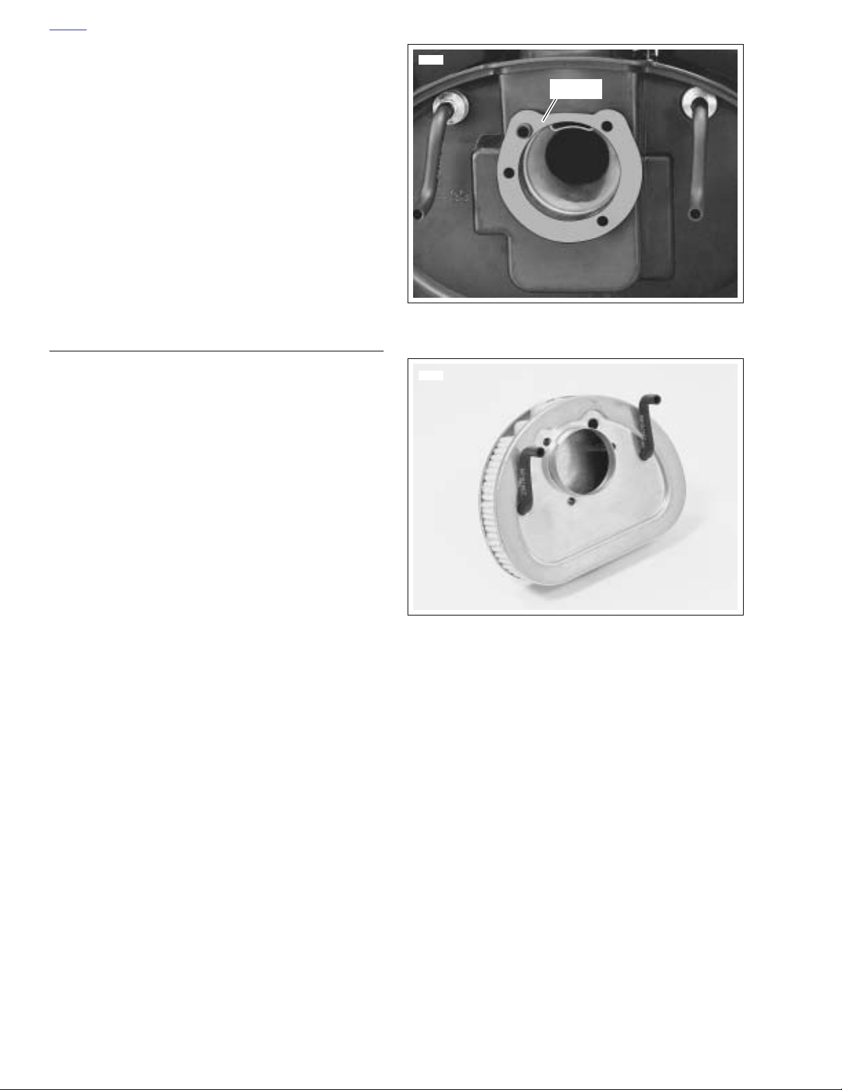
HOME
8. Inspect breather tubes for tears, cuts, holes or other
damage. Replace as necessary.
NOTE
The breather tubes allow crankcase vapors to be directed into
the air filter element. By providing effective recirculation of
crankcase vapor, the tubes serve to eliminate the pollutants
normally discharged from the crankcase. Air cleaner mounting without installation of the breather tubes, or with breather
tubes that are not air tight, allows crankcase vapors to be
vented into the atmosphere in violation of legal emissions
standards. This will also negatively affect the engine’s
breather system as it will cause the umbrella valve to flutter.
9. Wipe inside of air cleaner cover and backplate with damp
cloth to remove dust.
10. On California models only, make sure trap door swings
freely.
INSTALLATION
1. See Figure 1-40. Position new gasket on backplate.
2. See Figure 1-41. Insert two breather tubes into the holes
in back of the filter element and place the element back
into position. Attach breather tubes to breather screws
on backplate.
3. See Figure 1-39. Install air filter element and bracket.
a. Make sure gasket holes are aligned with backplate
holes.
b. Use three TORX screws (3) to secure bracket and
filter element. Tighten to 20-40 in-lbs (2.3-4.5 Nm).
4. Install air filter cover (2).
a. Apply a drop of LOCTITE THREADLOCKER 243
(blue) to threads of air cleaner cover screw (1).
b. Install air cleaner cover using screw. Tighten to 36-
60 in-lbs (4.1-6.8 Nm).
7429a
Gasket
Figure 1-40. Gasket Installation
7430
Figure 1-41. Breather Hose Holes on Backside of Filter
1-40 2006 Dyna: Maintenance
Page 43

HOME
CABLE AND CHASSIS LUBRICATION 1.21
GENERAL
Inspect and lubricate the front brake lever, clutch hand lever,
throttle control cables, clutch cable, foot shift lever, rear brake
lever bearings and jiffy stand.
CABLES AND HAND LEVERS
See 1.22 THROTTLE CABLES for throttle cables.
Use SUPER OIL (Part No. HD-94968-85TV) for hand levers
and cables.
JIFFY STAND
Clean and lubricate the jiffy stand.
If service is on muddy or dusty roads, clean and lubricate at
shorter intervals. See 2.28 JIFFY STAND for more informa-
tion.
2006 Dyna: Maintenance 1-41
Page 44
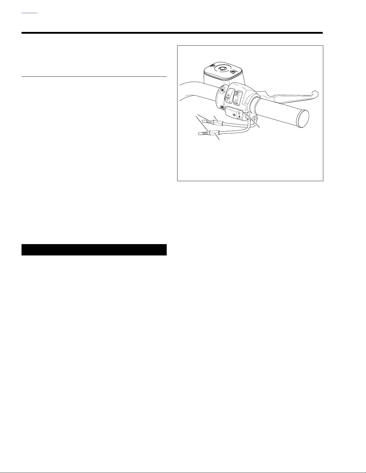
HOME
THROTTLE CABLES 1.22
CABLE INSPECTION,
LUBRICATION AND
ADJUSTMENT
Inspection and Lubrication
1. See Figure 1-42. Remove two screws (1) to separate the
upper handlebar housing from the lower housing.
2. Unhook each ferrule and cable from the throttle grip and
remove the throttle sleeve.
3. Apply a light coat of graphite to the handlebar and
replace throttle grip.
4. Put one or two drops of SUPER OIL (Part No. 94968-
85TV) into the housing of each cable.
5. When assembling the handlebar housing, tighten both
screws (1) to 35-45 in-lbs (4.0-5.1 Nm).
Adjustment
The throttle control must operate freely without binding. With
the throttle friction adjustment screw backed off, the throttle
grip must freely return to the closed (idle) position. The throttle control also must open and close freely when the front
wheel is turned to both the right and left fork stops. If the
throttle grip does not return to the idle position freely, check
the throttle friction adjustment screw tension. If the adjuster
screw is backed off, inspect the cables for short bends.
d0419x1x
3
2
4
1. Screws (2)
2. Throttle cable adjuster
3. Jam nuts (2)
4. Idle cable adjuster
Figure 1-42. Throttle Cable Adjusters
1
11WARNING1WARNING
Do not tighten throttle friction adjustment screw to the
point where the engine will not return to idle automatically. Over-tightening can lead to loss of vehicle control,
which could result in death or serious injury. (00031b)
1. Slide rubber boot off throttle cable adjuster mechanism.
See Figure 1-42. Holding cable adjuster with a 3/8 inch
wrench, loosen jam nut turning in a clockwise direction.
Back jam nut away from cable adjuster until it stops. Turn
cable adjuster clockwise until it contacts jam nut. Repeat
procedure on idle cable adjuster.
1-42 2006 Dyna: Maintenance
Page 45
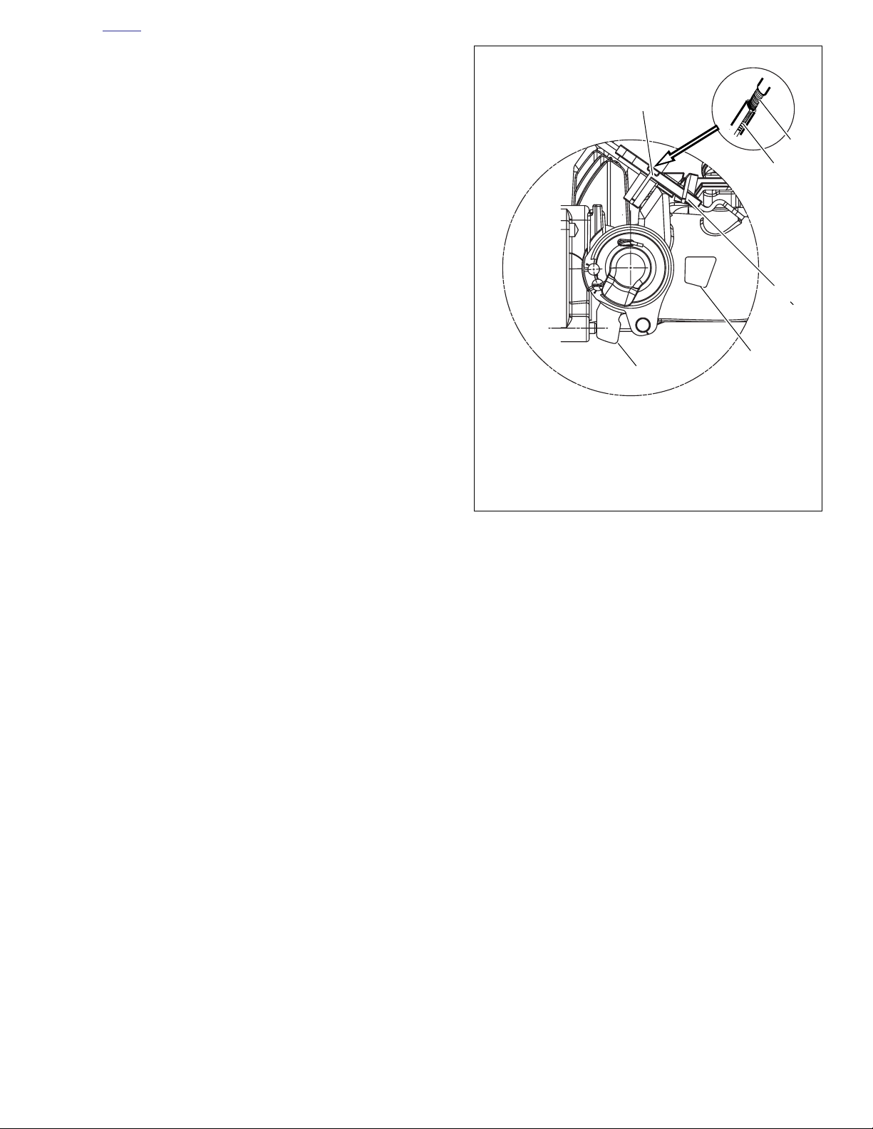
HOME
1. Throttle cable
2. Throttle cam
3. Idle cable
4. Idle cable housing
5. Cam stop
6. Spring
d0796x1x
1
3
2
4
5
6
2. Point the front wheel straight ahead. Gently turn the
throttle grip so that the throttle is wide open (fully counterclockwise) and then hold in position. Now turn the
cable adjuster counterclockwise until the throttle cam (2)
just touches the cam stop (5) on the induction module.
See Figure 1-43. Release the throttle grip, turn cable
adjuster counterclockwise an additional 1/2-1 full turn,
and then tighten the jam nut against the cable adjuster.
Cover cable adjuster mechanism with rubber boot.
3. Turn the front wheel full right. Turn the idle cable adjuster
counterclockwise until the cable housing (4) just touches
the spring (6) in the cable guide (as seen through slot).
Work the throttle grip to verify that the throttle cable
returns to the idle position when released. If the cable
does not return to idle, turn the cable adjuster clockwise
slightly until the correct response is achieved. Tighten
jam nut against the cable adjuster and cover cable
adjuster mechanism with rubber boot.
Figure 1-43. Induction Module Cable Connection
2006 Dyna: Maintenance 1-43
Page 46
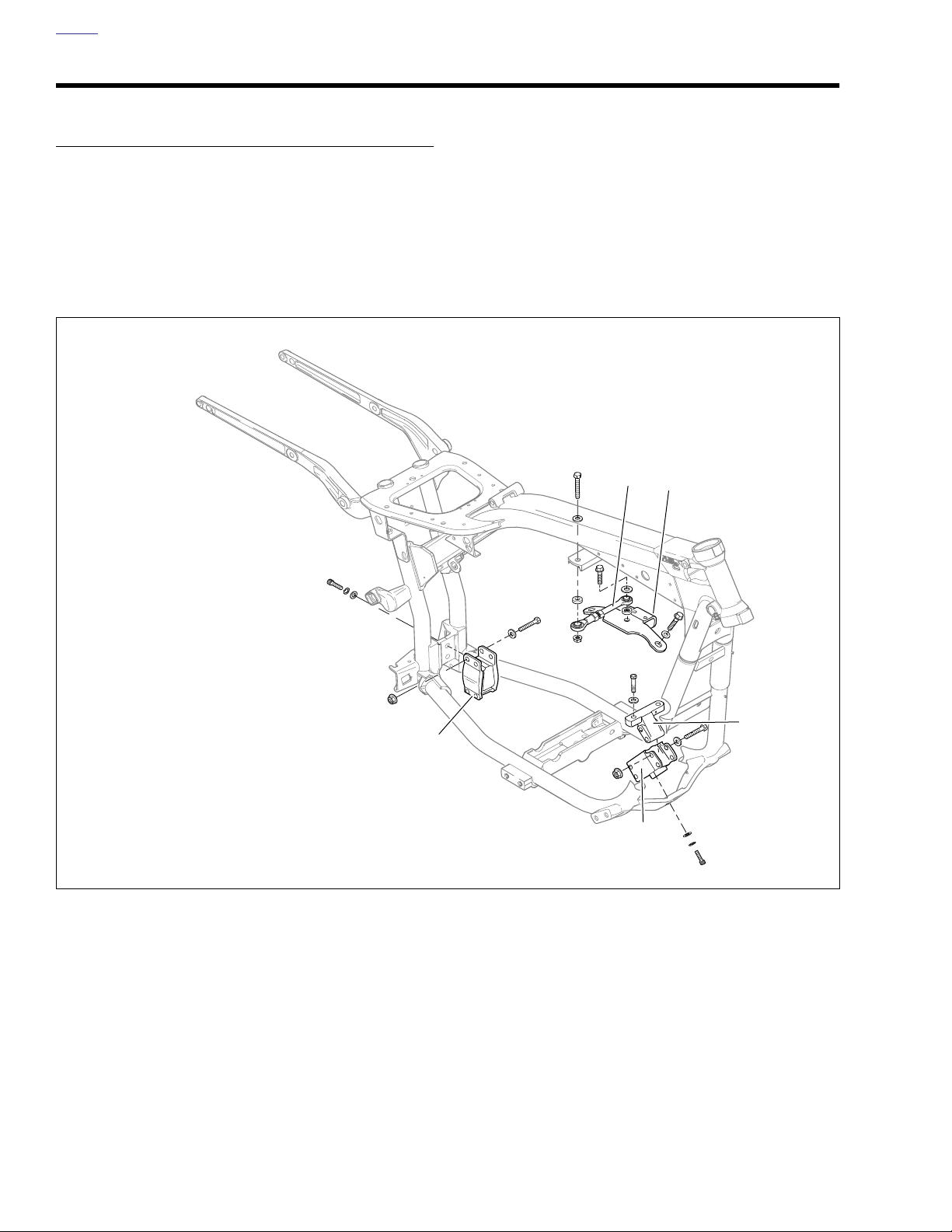
HOME
ENGINE MOUNTS 1.23
INSPECTION
1. See Figure 1-44. Check for cracks or tears in the mount
rubber.
2. Check stabilizer links for wear.
3. Check that all engine mount bolts are tight.
4. Check that all engine mount rivets are not sheared.
5. Check that the mounts are supporting the weight of the
motor.
d0738x1x
5
4
1. Rear isolator
2. Front isolator
3. Front engine mount bracket
4. Top engine mount bracket
5. Top stabilizer mount
3
1
2
Figure 1-44. Engine Mounts
1-44 2006 Dyna: Maintenance
Page 47
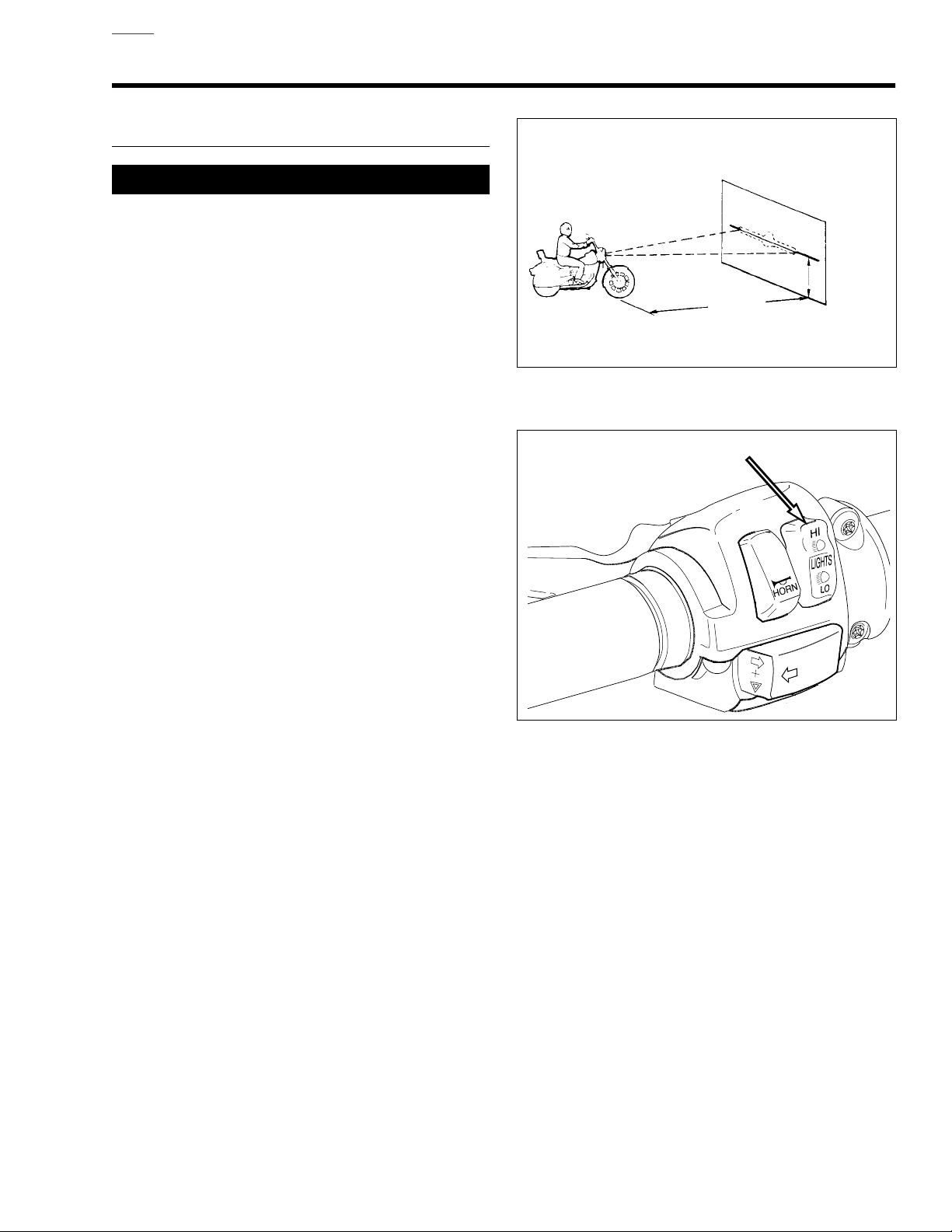
HOME
25 ft
(7.6 m)
d0110x1x
35 in.
(0.9 m)
d0417x1x
HEADLAMP ALIGNMENT 1.24
INSPECTION
11WARNING1WARNING
The automatic-on headlamp feature provides increased
visibility for riders. Be sure headlamp is on at all times.
Low visibility of rider can result in death or serious
injury. (00030a)
Check headlamp for proper height and lateral alignment:
● When the new owner takes delivery of the motorcycle.
● When there is a change in load (adding luggage, etc.)
1. Verify correct front and rear tire pressure. See 1.9 TIRES
AND WHEELS.
2. Place motorcycle on level floor (or pavement) in an area
with minimum light.
3. See Figure 1-45. Position motorcycle 25 ft (7.6 m) away
from a screen or wall. Measure the distance from directly
below the front axle to the base of the screen/wall.
4. Draw a horizontal line 35 in. (0.9 m) above floor on
screen/wall.
5. Load vehicle with rider, passenger (if normally present)
and any cargo. Weight will compress vehicle suspension
slightly.
6. Stand motorcycle upright with both tires resting on floor
and with front wheel held in straight alignment (directly
forward).
7. See Figure 1-46. Tu rn ignition switch ON. Set handlebar
headlamp switch to HIGH beam position.
8. Check light beam for alignment.
a. The main beam, which is a broad, flat pattern of
light, should be centered equally above and below
the horizontal line.
b. The main beam of light should also be directed
straight ahead. Properly adjusted headlamps project
an equal area of light to right and left of center.
c. Adjust headlamp alignment if necessary.
Figure 1-45. Checking Headlamp Alignment
Figure 1-46. Headlamp Switch High Beam Setting
2006 Dyna: Maintenance 1-45
Page 48
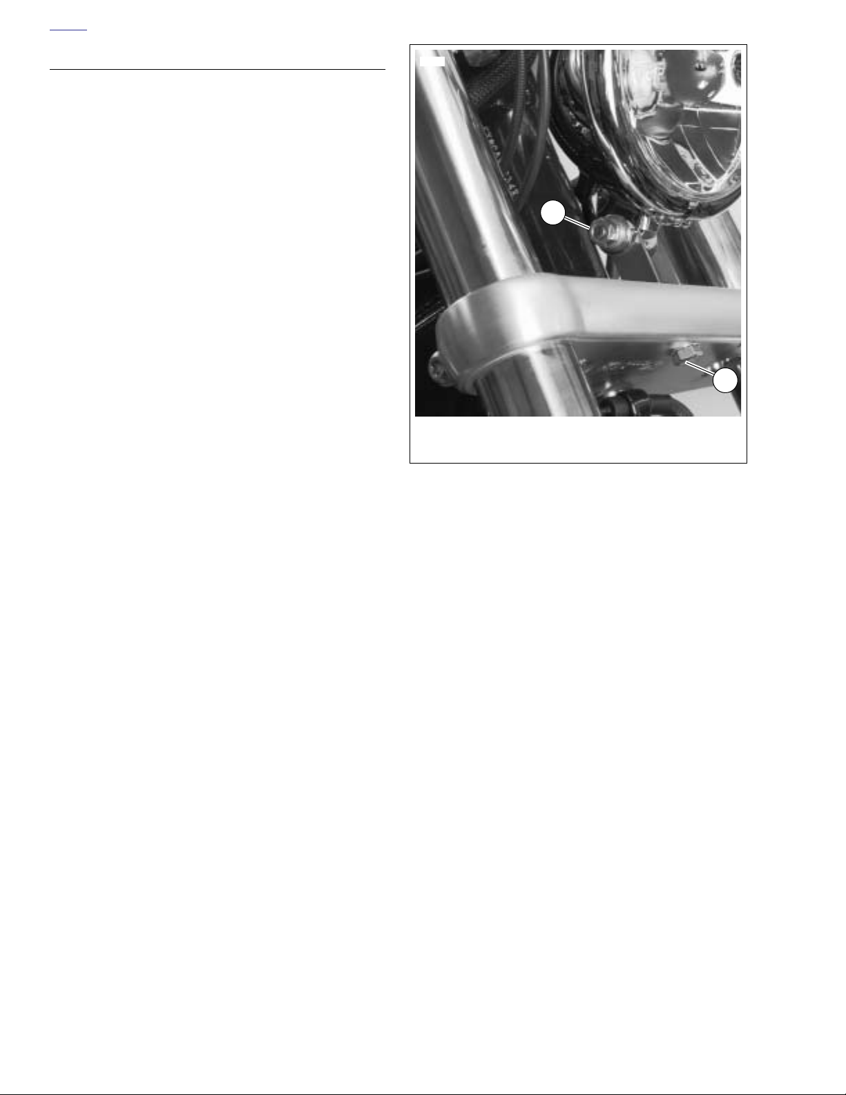
HOME
ADJUSTMENT
All Models
1. See Figure 1-47. Loosen horizontal adjusting bolt (2) to
adjust headlamp beam side to side. Tighten bolt to 25-30
ft-lbs (33.9-40.7 Nm).
2. Loosen nut on vertical adjusting bolt (1) to adjust headlamp beam up or down. Tighten nut to 25-30 ft-lbs (33.9-
40.7 Nm).
11327
1
2
1. Vertical adjusting bolt
2. Horizontal adjusting bolt
Figure 1-47. Headlamp Adjustments
1-46 2006 Dyna: Maintenance
Page 49
HOME
CRITICAL FASTENERS 1.25
INSPECTION
Refer to Ta ble 1-7. Tighten all critical fasteners, except head
bolts, to service manual specifications. Replace any damaged or missing hardware.
Table 1-7. Critical Fasteners
SYSTEM FASTENER TORQUE
Upper and lower switch housings 35-45 in-lbs 4.0-5.1 Nm
Hand controls
Brakes
Axle nuts
Front fork/handlebars
Clutch lever handlebar clamp 60-80 in-lbs 6.8-9.0 Nm
Master cylinder handlebar clamp 60-80 in-lbs 6.8-9.0 Nm
Banjo bolts 17-22 ft-lbs 23.0-29.8 Nm
Lower brake caliper mounting pin 28-38 ft-lbs 38.0-51.5 Nm
Brake disc screws, front 16-24 ft-lbs 21.7-32.5 Nm
Brake disc screws, rear 30-35 ft-lbs 40.7-47.5 Nm
Brake disc screws, rear (allen) 23-27 ft-lbs 31.2-36.6 Nm
Reservoir screws 6-8 in-lbs 0.7-0.9 Nm
Rear master cylinder mounting nut 40-50 ft-lbs 54.2-67.8 Nm
Front axle 50-55 ft-lbs 67.8-74.6 Nm
Rear axle 60-65 ft-lbs 81.3-88.1 Nm
Lower fork pinch bolts 30-35 ft-lbs 40.7-47.5 Nm
Slider bolts 108-156 in-lbs 12.2-17.6 Nm
Upper bracket pinch bolts 21-27 ft-lbs 28.5-36.6 Nm
Handlebar clamp mounting screw 70-80 in-lbs 7.9-9.0 Nm
Riser clamp screws 144-180 in-lbs 16.3-20.3 Nm
Riser lock nuts 30-40 ft-lbs 40.7-54.2 Nm
2006 Dyna: Maintenance 1-47
Page 50

HOME
STORAGE 1.26
GENERAL
11WARNING1WARNING
Do not store motorcycle with gasoline in tank within the
home or garage where open flames, pilot lights, sparks
or electric motors are present. Gasoline is extremely
flammable and highly explosive, which could result in
death or serious injury. (00003a)
If the motorcycle will not be operated for several months,
such as during the winter season, there are several things
which should be done to protect parts against corrosion, to
preserve the battery, and to prevent the buildup of gum and
varnish in the fuel system.
This work should be performed by a local Harley-Davidson
dealer or other qualified technician following the procedures
in this service manual.
1. Run motorcycle until engine is at normal operating temperature. Stop the engine then drain the oil pan, install a
new oil filter, and fill oil pan with the proper grade oil.
Check the transmission lubricant level.
3. Remove the spark plugs, inject a few squirts of engine oil
into each cylinder and crank the engine 5-6 revolutions.
Reinstall spark plugs.
4. Inspect rear belt deflection. See 1.14 REAR BELT
DEFLECTION.
5. Inspect rear belt and sprockets. See 1.15 REAR BELT
AND SPROCKETS.
6. Inspect air cleaner filter. See 1.20 AIR CLEANER FIL-
TER.
7. Lubricate controls. See 1.21 CABLE AND CHASSIS
LUBRICATION.
8. Inspect operation of all electrical equipment and
switches.
9. Check tire inflation and inspect tires for wear and/or damage. See 1.9 TIRES AND WHEELS. If the motorcycle will
be stored for an extended period of time, securely support the motorcycle under the frame so that all weight is
off the tires.
11WARNING1WARNING
Be sure that brake fluid or other lubricants do not contact brake pads or discs. Such contact can adversely
affect braking ability, which could cause loss of control,
resulting in death or serious injury. (00290a)
10. Wash painted and chrome-plated surfaces. Apply a light
film of oil to exposed unpainted surfaces.
11WARNING1WARNING
Avoid spills. Slowly remove filler cap. Do not fill above
bottom of filler neck insert, leaving air space for fuel
expansion. Secure filler cap after refueling. Gasoline is
extremely flammable and highly explosive, which could
result in death or serious injury. (00028a)
11WARNING1WARNING
Use care when refueling. Pressurized air in fuel tank can
force gasoline to escape through filler tube. Gasoline is
extremely flammable and highly explosive, which could
result in death or serious injury. (00029a)
2. Prepare your fuel system by filling fuel tank and adding a
gasoline stabilizer. Use one of the commercially available
gasoline stabilizers following the manufacturer’s instructions.
1-48 2006 Dyna: Maintenance
Page 51

HOME
11WARNING1WARNING
11WARNING1WARNING
● Unplug or turn OFF battery charger before connect-
ing charger cables to battery. Connecting cables
with charger ON can cause a spark and battery
explosion, which could result in death or serious
injury. (00066a).
● Explosive hydrogen gas, which escapes during
charging, could cause death or serious injury.
Charge battery in a well-ventilated area. Keep open
flames, electrical sparks and smoking materials
away from battery at all times. KEEP BATTERIES
AWAY FROM CHILDREN. (00065a)
11. Remove battery from vehicle. Charge battery until the
correct voltage is obtained. Charge the battery every
other month if it is stored at temperatures below 60˚ F
(16˚ C). Charge battery once a month if it is stored at
temperatures above 60˚ F (16˚ C). See 1.5 BATTERY
MAINTENANCE.
1CAUTION
Unplug or turn OFF battery charger before disconnecting
charger cables from battery. Disconnecting clamps with
charger ON can cause a spark and battery explosion,
which could result in death or serious injury. (00067a)
12. If the motorcycle is to be covered, use a material that will
breathe, such as light canvas or Part No. 98716-87A.
Plastic materials that do not breathe promote the formation of condensation, which leads to corrosion.
REMOVAL FROM STORAGE
The clutch failing to disengage can cause loss of control,
which could result in death or serious injury. Prior to
starting after extended periods of storage, place transmission in gear and push vehicle back and forth several
times to assure proper clutch disengagement. (00075a)
1. Charge and install the battery.
2. Remove and inspect the spark plugs. Replace if necessary.
3. Clean the air cleaner element.
4. If fuel tank was drained, fill fuel tank with fresh gasoline.
5. Start the engine and run until it reaches normal operating temperature.
6. Check engine oil level. Check the transmission lubricant
level. Fill to proper levels with correct fluids, if required.
7. Perform all of the checks in the PRE-RIDING CHECKLIST in the Owner’s Manual.
2006 Dyna: Maintenance 1-49
Page 52

HOME
TROUBLESHOOTING 1.27
GENERAL
11WARNING1WARNING
The troubleshooting section of this manual is a guide to
diagnose problems. Read the appropriate sections of
this manual before performing any work. Improper repair
and/or maintenance could result in death or serious
injury.
The following check list of possible operating troubles and their
probable causes will be helpful in keeping a motorcycle in good
operating condition. More than one of these conditions may be
causing the trouble and all should be carefully checked.
ENGINE
Starter Motor Does Not Operate or Does
Not Turn Engine Over
1. Ignition switch not in ON position.
2. Engine run switch in OFF position.
3. Discharged battery, loose or corroded connections (solenoid chatters).
4. Starter control circuit, relay, or solenoid faulty.
5. Electric starter shaft pinion gear not engaging or overrunning clutch slipping.
6. TSM/TSSM Bank Angle Sensor tripped and ignition
switch not cycled OFF then ON.
Engine Turns Over But Does Not Start
1. Fuel tank empty.
2. Fouled spark plugs.
3. Discharged battery, loose or broken battery terminal connections.
4. Engine lubricant too heavy (winter operation).
NOTE
For cold weather starts, always disengage clutch.
5. Spark plug cables in bad condition and shorting, cable
connections loose or cables connected to incorrect cylinders.
6. Loose wire connection at coil, battery or ECM connector.
7. Ignition timing incorrect due to faulty coil, ECM or sensors (MAP, CKP and/or TSM/TSSM).
Starts Hard
1. Spark plugs in bad condition or have improper gap or are
partially fouled.
2. Spark plug cables in bad condition.
3. Battery nearly discharged.
4. Loose wire connection at one of the battery terminals,
coil or ECM connector.
5. Water or dirt in fuel system.
6. Intake air leak.
7. Fuel tank vent hose and vapor valve plugged.
8. Engine lubricant too heavy (winter operation).
NOTE
For cold weather starts, always disengage clutch.
9. Ignition not functioning properly (possible sensor failure).
10. Faulty ignition coil.
11. Valves sticking.
Starts But Runs Irregularly or Misses
1. Spark plugs in bad condition or partially fouled.
2. Spark plug cables in bad condition and leaking.
3. Spark plug gap too close or too wide.
4. Faulty ignition coil, ECM, or sensor.
5. Battery nearly discharged.
6. Damaged wire or loose connection at battery terminals,
coil or ECM connector.
7. Intermittent short circuit due to damaged wire insulation.
8. Water or dirt in fuel system.
9. Fuel tank vent system plugged.
10. Air leak at intake manifold or air cleaner.
11. Loose or dirty ECM connector.
12. Faulty Sensor(s): Manifold Absolute Pressure (MAP),
Crank Position (CKP) or Oxygen (O2).
13. Incorrect valve timing.
14. Weak or broken valve springs.
15. Damaged intake or exhaust valve.
1-50 2006 Dyna: Maintenance
Page 53

HOME
A Spark Plug Fouls Repeatedly
1. Fuel mixture too rich.
2. Incorrect spark plug for the kind of service.
3. Piston rings badly worn or broken.
4. Valve guides or seals badly worn.
Pre-Ignition or Detonation (Knocks or
Pings)
1. Fuel octane rating too low.
2. Faulty spark plugs.
3. Incorrect spark plug for the kind of service.
4. Excessive carbon deposit on piston head or in combustion chamber.
5. Ignition timing advanced due to faulty sensor inputs
(MAP and/or CKP).
Overheating
1. Insufficient oil supply or oil not circulating.
2. Insufficient air flow over engine.
3. Heavy carbon deposit.
4. Ignition timing retarded due to faulty sensor(s): Manifold
Absolute Pressure (MAP) and/or Crank Position (CKP).
5. Leaking valve.
Valve Train Noise
1. Low oil pressure caused by oil feed pump not functioning
properly or oil passages obstructed.
2. Faulty hydraulic lifters.
3. Bent push rod.
4. Incorrect push rod length.
5. Rocker arm binding on shaft.
6. Valve sticking in guide.
7. Chain tensioner or shoe worn.
Excessive Vibration
1. Wheels and/or tires worn or damaged.
2. Engine/transmission/rear wheel not aligned properly.
3. Primary chain badly worn or links tight as a result of
insufficient lubrication or misalignment.
4. Engine to transmission mounting bolts loose.
5. Upper engine mounting bracket loose.
6. Ignition timing advanced due to faulty sensor inputs
(MAP and/or CKP)/poorly tuned engine.
7. Internal engine problem.
8. Broken frame.
Check Engine Light Illuminates During
Operation
1. Fault detected. See CHECKING FOR TROUBLE
CODES in DYNA MODELS ELECTRICAL DIAGNOSTIC MANUAL for more information.
LUBRICATION SYSTEM
Oil Does Not Return To Oil Pan
1. Oil pan empty.
2. Oil pump not functioning.
3. Restricted oil lines or fittings.
4. Restricted oil filter.
5. Oil pump misaligned or in poor condition.
6. O-ring damaged or missing from oil pump/crankcase
junction (also results in poor engine performance).
Engine Uses Too Much Oil Or Smokes
Excessively
1. Oil pan overfilled.
2. Restricted oil return line to pan.
3. Restricted breather operation.
4. Restricted oil filter.
5. Oil pump misaligned or in poor condition.
6. Piston rings badly worn or broken.
7. Valve guides or seals worn.
8. O-ring damaged or missing from oil pump/crankcase
junction (also results in poor engine performance).
9. Plugged crankcase scavenge port.
Engine Leaks Oil From Cases, Push Rods,
Hoses, Etc.
1. Loose parts.
2. Imperfect seal at gaskets, push rod cover, washers, etc.
3. Restricted breather hose to air cleaner.
4. Restricted oil filter.
5. Oil pan overfilled.
6. Lower rocker housing gasket installed incorrectly (upside
down).
7. Restricted oil return line to tank.
2006 Dyna: Maintenance 1-51
Page 54

HOME
1. Oil pan underfilled.
2. Faulty low oil pressure switch.
3. Oil pump O-ring damaged or missing.
4. Bypass valve stuck in open position.
5. Ball missing or leaking in cam support plate.
1. Oil pan overfilled.
2. Bypass valve stuck in closed position.
1. Voltage regulator/rectifier module not grounded.
2. Engine ground wire loose or broken.
3. Faulty regulator-rectifier module.
4. Loose or broken wires in charging circuit.
5. Faulty stator and/or rotor.
1. Primary chaincase overfilled with lubricant.
2. Clutch dragging slightly.
3. Transmission lubrication too heavy (winter operation).
4. Shifter return spring (inside transmission) bent or broken.
5. Bent shifter rod.
6. Shifter forks (inside transmission) sprung.
7. Corners worn off shifter dog rings (inside transmission).
1. Shifter rod improperly adjusted.
2. Shifter drum (inside transmission) damaged.
3. Shifter engaging parts (inside transmission) badly worn
and rounded.
4. Shifter forks bent.
5. Damaged gears.
1. Weak or damaged battery.
2. Loose connections.
3. Faulty regulator-rectifier module.
4. Faulty stator and/or rotor.
1. Contaminated vehicle speed sensor (remove sensor and
clean off metal particles).
2. Loose connections.
1. Clutch controls improperly adjusted.
2. Insufficient clutch spring tension.
3. Worn friction discs.
1. Lubricant level too high in primary chaincase.
2. Clutch controls improperly adjusted.
3. Primary chain badly misaligned.
4. Clutch spring tension.
5. Clutch discs warped.
1. Friction discs or steel discs worn or warped.
Page 55

HOME
HANDLING
Irregularities
1. Improperly loaded motorcycle. Non-standard equipment
on the front end such as heavy radio receivers, extra
lighting equipment or luggage tends to cause unstable
handling.
2. Damaged tire(s) or improper front-rear tire combination.
3. Irregular or peaked front tire tread wear.
4. Incorrect tire pressure. See 1.9 TIRES AND WHEELS.
5. Shock absorber not functioning normally.
6. Loose wheel axle nuts. Tighten to recommended torque
specification.
7. Excessive wheel hub bearing play.
8. Rear wheel out of alignment with frame and front wheel.
9. Steering head bearings improperly adjusted. Correct
adjustment and replace pitted or worn bearings and
races. See 1.17 STEERING HEAD BEARINGS.
10. Loose spokes (laced wheel vehicles only).
11. Tire and wheel unbalanced.
12. Rims and tires out-of-round or eccentric with hub.
13. Rims and tires out-of-true sideways.
14. Rear fork pivot.
BRAKES
Brake Does Not Hold Normally
1. Master cylinder reservoir low on fluid.
2. Brake system contains air bubbles.
3. Master cylinder or caliper piston seals worn or parts
damaged.
4. Brake pads contaminated with grease or oil.
5. Brake pads badly worn.
6. Brake disc badly worn or warped.
7. Brake drags – insufficient brake pedal freeplay.
8. Brake fades due to heat build up – brake pads dragging
or excessive braking.
9. Brake fluid leak when under pressure.
2006 Dyna: Maintenance 1-53
Page 56

HOME
NOTES
1-54 2006 Dyna: Maintenance
Page 57
CHASSIS 2
T
able Of Contents
SUBJECT PAGE NO.
2.1 Specifications . . . . . . . . . . . . . . . . . . . . . . . . . . . . . . . . . . . . . . . . . . . . . . . . . . 2-1
2.2 Torque Values . . . . . . . . . . . . . . . . . . . . . . . . . . . . . . . . . . . . . . . . . . . . . . . . . . 2-2
2.3 Vehicle Identification Number (V.I.N.) . . . . . . . . . . . . . . . . . . . . . . . . . . . . . . . . 2-4
2.4 Front Wheel . . . . . . . . . . . . . . . . . . . . . . . . . . . . . . . . . . . . . . . . . . . . . . . . . . . . 2-6
2.5 Rear Wheel . . . . . . . . . . . . . . . . . . . . . . . . . . . . . . . . . . . . . . . . . . . . . . . . . . . . 2-11
2.6 Sealed Wheel Bearings . . . . . . . . . . . . . . . . . . . . . . . . . . . . . . . . . . . . . . . . . . . 2-15
2.7 Wheel Lacing: 17 In. Rim . . . . . . . . . . . . . . . . . . . . . . . . . . . . . . . . . . . . . . . . . 2-18
2.8 Wheel Lacing: 19 In. Rim . . . . . . . . . . . . . . . . . . . . . . . . . . . . . . . . . . . . . . . . . 2-21
2.9 Wheel Lacing: 21 In. Rim . . . . . . . . . . . . . . . . . . . . . . . . . . . . . . . . . . . . . . . . . 2-26
2.10 Truing Laced Wheel . . . . . . . . . . . . . . . . . . . . . . . . . . . . . . . . . . . . . . . . . . . . 2-29
2.11 Cast Wheel Runout . . . . . . . . . . . . . . . . . . . . . . . . . . . . . . . . . . . . . . . . . . . . . 2-32
2.12 Tires . . . . . . . . . . . . . . . . . . . . . . . . . . . . . . . . . . . . . . . . . . . . . . . . . . . . . . . . 2-33
2.13 Vehicle Alignment . . . . . . . . . . . . . . . . . . . . . . . . . . . . . . . . . . . . . . . . . . . . . . 2-36
2.14 Front Brake Master Cylinder . . . . . . . . . . . . . . . . . . . . . . . . . . . . . . . . . . . . . . 2-39
2.15 Rear Brake Master Cylinder . . . . . . . . . . . . . . . . . . . . . . . . . . . . . . . . . . . . . . 2-45
2.16 Front Brake Caliper . . . . . . . . . . . . . . . . . . . . . . . . . . . . . . . . . . . . . . . . . . . . . 2-48
2.17 Rear Brake Caliper . . . . . . . . . . . . . . . . . . . . . . . . . . . . . . . . . . . . . . . . . . . . . 2-53
2.18 Front Fork . . . . . . . . . . . . . . . . . . . . . . . . . . . . . . . . . . . . . . . . . . . . . . . . . . . . 2-58
2.19 Steering Head . . . . . . . . . . . . . . . . . . . . . . . . . . . . . . . . . . . . . . . . . . . . . . . . . 2-63
2.20 Rear Shock Absorbers . . . . . . . . . . . . . . . . . . . . . . . . . . . . . . . . . . . . . . . . . . 2-66
2.21 Rear Fork . . . . . . . . . . . . . . . . . . . . . . . . . . . . . . . . . . . . . . . . . . . . . . . . . . . . 2-68
2.22 Belt Guard . . . . . . . . . . . . . . . . . . . . . . . . . . . . . . . . . . . . . . . . . . . . . . . . . . . . 2-70
2.23 Debris Deflector . . . . . . . . . . . . . . . . . . . . . . . . . . . . . . . . . . . . . . . . . . . . . . . . 2-71
2.24 Throttle Control . . . . . . . . . . . . . . . . . . . . . . . . . . . . . . . . . . . . . . . . . . . . . . . . 2-72
2.25 Clutch Control . . . . . . . . . . . . . . . . . . . . . . . . . . . . . . . . . . . . . . . . . . . . . . . . . 2-74
2.26 Front Fender . . . . . . . . . . . . . . . . . . . . . . . . . . . . . . . . . . . . . . . . . . . . . . . . . . 2-75
2.27 Rear Fender . . . . . . . . . . . . . . . . . . . . . . . . . . . . . . . . . . . . . . . . . . . . . . . . . . 2-76
2.28 Jiffy Stand . . . . . . . . . . . . . . . . . . . . . . . . . . . . . . . . . . . . . . . . . . . . . . . . . . . . 2-79
2.29 Fork Lock . . . . . . . . . . . . . . . . . . . . . . . . . . . . . . . . . . . . . . . . . . . . . . . . . . . . 2-80
2.30 Seat . . . . . . . . . . . . . . . . . . . . . . . . . . . . . . . . . . . . . . . . . . . . . . . . . . . . . . . . . 2-81
2.31 Engine Mounts . . . . . . . . . . . . . . . . . . . . . . . . . . . . . . . . . . . . . . . . . . . . . . . . 2-82
Page 58

Page 59
2
HOME
SPECIFICATIONS 2.1
ITEM
Wheel base 64.2 1630 64.2 1630 64.6 1640 68.3 1735 64.2 1630 64.2 1630
Overall length 92.8 2357 92.6 2353 93.1 2364 97.5 2477 92.9 2360 92.8 2358
Overall width 36.7 931 34.9 886 36.3 921 36 915 38.9 989 37.5 953
Road clearance 6.0 153 6.0 153 5.6 142 6.2 158 6.0 153 5.6 142
Overall height 46.8 1189 47.6 1210 47.0 1194 49.3 1251 47.7 1212 50.4 1279
Saddle height 27.6 700 27.8 705 26.8 680 28.5 723 27.8 705 26.8 680
MODEL
FXDWG/FXD35 29.6** 0.875** 5.1 19.3 1.2 4.5
FXDL/FXDB/
FXD35
FXD/C 4.8 18.2 0.8-1.2 3.0-4.5
* Reserve when low fuel light illuminates.
**FXD35 fork fluid capacity is same as FXD
FXD FXDC FXDL FXDWG FXD35 FXDB
in. mm in. mm in. mm in. mm in. mm in. mm
FRONT FORK
oz. liter gal. liter gal. liter qt. liter oz. liter oz. liter
26.6 0.787
FUEL TANK
TOTAL
4.7 17.8 0.8-1.2 3.0-4.5
FUEL TANK
RESERVE *
OIL TANK
W/FILTER
3.0 2.8 32.0 0.95 32.0 0.95
TRANSMISSION
(APPROX.)
PRIMARY
CHAINCASE
ITEM
Weight (as
shipped from
factory)
GVWR 1085 493 1085 493 1085 493 1085 493 1085 493 1085 493
GAWR front 390 177 390 177 390 177 390 177 390 177 390 177
GAWR rear 695 316 695 316 695 316 695 316 695 316 695 316
Gross vehicle weight rating (GVWR) (maximum allowable
loaded vehicle weight) and corresponding gross axle weight
rating (GAWR) are given on a label located on the frame
steering head.
FXD FXDC FXDL FXDWG FXD35 FXDB
lb. kg lb. kg lb. kg lb. kg lb. kg lb. kg
632 287 641 291 641 291 650 295 645 293 634 285
NOTE
See 1.9 TIRES AND WHEELS for important information
regarding tire data and tire inflation.
NOTE
2006 Dyna: Chassis 2-1
Page 60
HOME
TORQUE VALUES 2.2
ITEM TORQUE NOTES
Axle cap fastener 12 ft-lbs 16.3 Nm page 2-10
Belt guard fasteners 10-15 ft-lbs 13.6-20.3 Nm page 2-70
Belt sprocket screws 55-60 ft-lbs 74.6-81.3 Nm
Brake disc screws, front 16-24 ft-lbs 21.7-32.5 Nm page 2-8
Brake disc screws, rear 30-45 ft-lbs 40.7-61.0 Nm
Debris deflector screws 40-60
Fork stem nut 35-40 ft-lbs 47.5-54.2 Nm page 2-65
Fork tube caps 16-43 ft-lbs 22-58 Nm page 2-62
Front axle nut 50-55 ft-lbs 67.8-74.6 Nm page 2-9
Front brake caliper bleeder
valve
Front brake caliper bridge bolts 28-38 ft-lbs 38.0-51.5 Nm page 2-50
Front brake caliper lower
mounting bolt
Front brake caliper top mounting bolt
Front brake reservoir cover
screws
Front fender nuts 15-21 ft-lbs 20.3-28.5 Nm page 2-75
in-lbs
80-100
in-lbs
28-38 ft-lbs 38.0-51.5 Nm Short bolt, 12 pt/10 mm, page 2-11, page 2-51
28-38 ft-lbs 38.0-51.5 Nm Long bolt, 12 pt/10 mm, page 2-11, page 2-51
6-8
in-lbs
4.5-6.8 Nm page 2-14, page 2-71
9.0-11.3 Nm page 2-50
0.7-0.9 Nm page 2-52
Apply several drops of LOCTITE® thread locker 262
(red) to last few threads. page 2-12
Apply several drops of LOCTITE® thread locker 243
(blue) to last few threads. page 2-12
Front master cylinder banjo
bolt
Isolator mounting bolts 25 ft-lbs 33.9 Nm page 2-38
Jiffy stand bolt 19 ft-lbs 25.8 Nm page 2-79
Lower shock mounting fasteners
Master cylinder clamp screw 70-80
Pivot shaft nut 71-75 ft-lbs 96.3-101.7 Nm page 2-69
Rear axle nut 60-65 ft-lbs 81.3-88.1 Nm page 2-14
Rear brake caliper bleeder
valve
Rear brake caliper bridge bolts 28-38 ft-lbs 38.0-51.5 Nm page 2-56
Rear brake pad pins 15-16 ft-lbs 20.3-22.6 Nm 12 pt/0.25 in., page 2-51, page 2-57
Rear brake reservoir cover
screws
Rear master cylinder banjo
bolt
Rear master cylinder mounting nut
17-22 ft-lbs 23.0-29.8 Nm page 2-43
30-40 ft-lbs 40.7-54.2 Nm page 2-14, page 2-67
in-lbs
80-100
in-lbs
6-8
in-lbs
17-22 ft-lbs 23.0-29.8 Nm page 2-47
40-50 ft-lbs 54.2-67.8 Nm page 2-47
7.9-9.0 Nm T27 TORX, page 2-43
9.0-11.3 Nm page 2-56
0.7-0.9 Nm page 2-47
2-2 2006 Dyna: Chassis
Page 61
HOME
ITEM TORQUE NOTES
Seat pipe screw 106-159
Seat strap nut 60-90
Spoke nipples 55-65
Throttle housing screws 35-45
Upper shock mounting fasteners
Upper shock mounting fasteners
Valve stem nut 12-15
Wheel spoke nipples 55-65
75-85 ft-lbs 101.7-115.2 Nm page 2-14
75-85 ft-lbs 101.7-115.2 Nm page 2-67
in-lbs
in-lbs
in-lbs
in-lbs
in-lbs
in-lbs
12-18 Nm page 2-62
6.78-10.17 Nm page 2-81
6.2-7.3 Nm page 2-20, page 2-25, page 2-28
4.0-5.1 Nm page 2-72
1.4-1.7 Nm page 2-34
6.2-7.3 Nm page 2-31
2006 Dyna: Chassis 2-3
Page 62
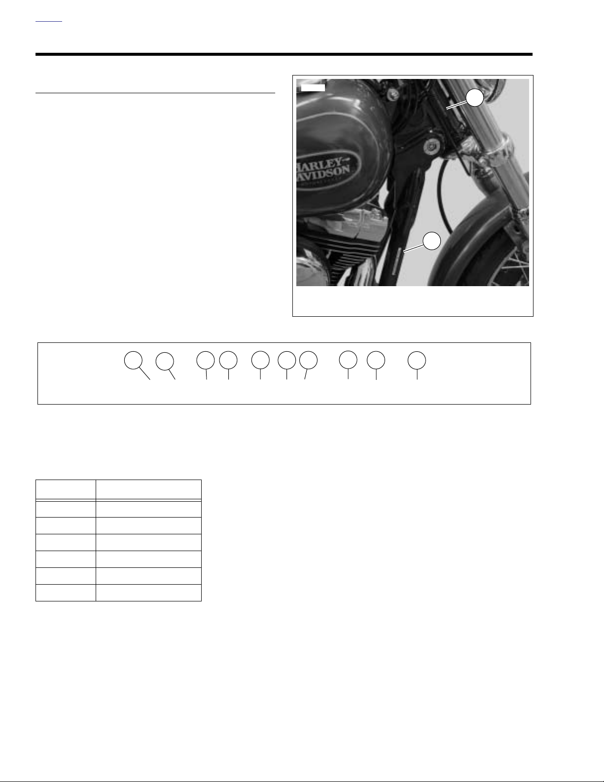
HOME
VEHICLE IDENTIFICATION NUMBER (V.I.N.) 2.3
GENERAL
See Figure 2-1. The full 17 digit serial, or Vehicle Identifica-
tion Number (V.I.N.) is stamped on the right side of the steering head and on a label located on the right side down tube.
An abbreviated V.I.N. is stamped on the left side crankcase at
the base between the cylinders.
Sample V.I.N. as it appears on the steering head -
1HD1GP1116K110000
Sample abbreviated V.I.N. as it appears on the left crankcase
GP16110000
NOTE
Always give the full 17 digit Vehicle Identification Number
when ordering parts or making any inquiry about your motorcycle.
1
2
4
3
5
12209
1. Stamping
2. Label
7
6
2
Figure 2-1. V.I.N. Location
8
9
10
1
1HD1GP 1 1 8 6 K 300000
Figure 2-2. Dyna Vehicle Identification Number (typical
Table 2-1. 2006 Dyna Model
V.I.N. Codes
CODE MODEL NAME
GM FXD
GN FXDL
GP FXDWG
GV FXDC
GW FXD35
GX FXDB
2-4 2006 Dyna: Chassis
Page 63
HOME
Table 2-2. Harley-Davidson 2006 Dyna Model V.I.N. Description
ITEM DESCRIPTION POSSIBLE VALUES
1 Market destination 1=Originally manufactured for sale within
States
5=Originally manufactured for sale outside
States
2 Manufacturer and make HD=Harley-Davidson
3 Motorcycle type 1=Heavyweight motorcycle 901 cc and larger
4 Model see model V.I.N. table
5 Engine type 1=Twin Cam 88, 1450cc air-cooled, fuel injected
6 Introduction date 1=Regular
2=Mid-year
3=California/regular
4=Cosmetic changes and/or special introductory date
5=California/cosmetic changes and/or special introductory date
6=California/mid-year
7 VIN check digit Can be 0-9 or X
8 Model year 6=2006
9 Plant of manufacture K=Kansas City, MO., U.S.A.
10 Sequential number (last 6 digits) varies
the United
of the United
2006 Dyna: Chassis 2-5
Page 64
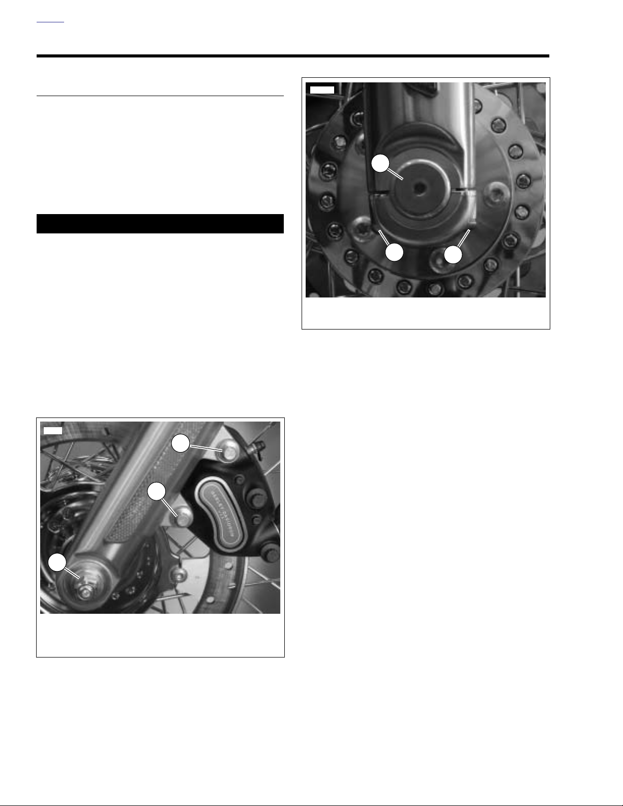
HOME
FRONT WHEEL 2.4
REMOVAL
1. Block motorcycle underneath frame so front wheel is
raised off the ground.
2. Inspect wheel bearing end play and service bearings if
necessary. See 2.6 SEALED WHEEL BEARINGS.
3. See Figure 2-3. Remove brake caliper. Support caliper
using a rubber bungee cord.
CAUTION
Be careful not to scratch the fender paint.
NOTE
Do not operate front brake lever with the front wheel removed
or the caliper piston may be forced out of piston bore. Reseating the piston requires disassembly of the caliper.
4. Remove axle nut, lockwasher and washer (3).
5. See Figure 2-4. Loosen the slider cap screws (2) and pull
the axle (1) free.
12206
1
2
1. Axle
2. Slider cap screws and washers (metric)
Figure 2-4. Front Wheel Mounting (Right Side)
2
6. Remove wheel from forks.
11329
1
2
3
1. Long mounting bolt (12 pt/10 mm)
2. Short mounting bolt (12 pt/10 mm)
3. Axle nut, lockwasher and washer
Figure 2-3. Caliper Mounting Bolts (Left Side)
2-6 2006 Dyna: Chassis
Page 65
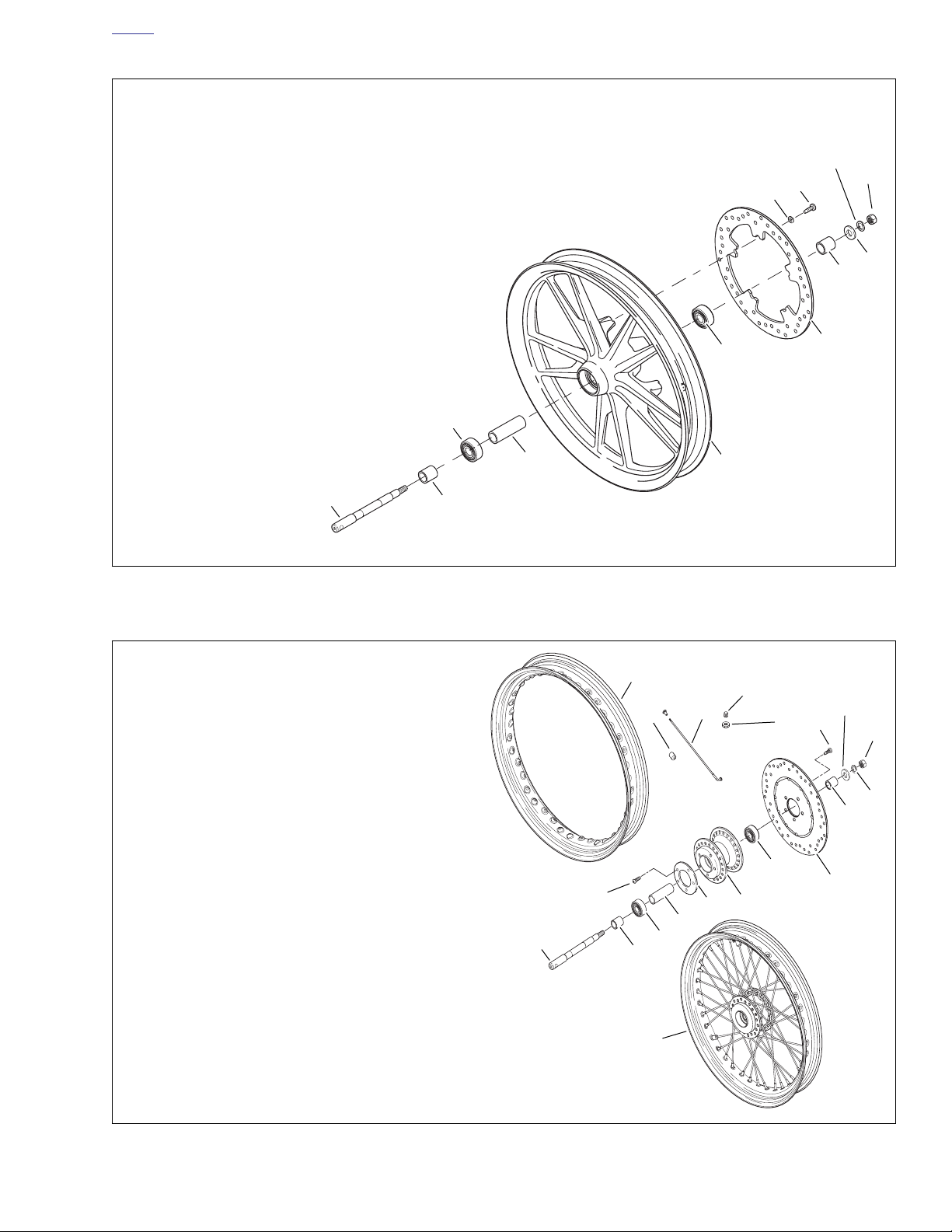
HOME
1. Axle
2. Right bearing spacer
3. Screw (5)
4. Washer (5)
5. Bearing (2)
6. Sleeve
7. Cast wheel
8. Brake disc
9. Left bearing spacer
10. Washer
11. Lockwasher
12. Axle nut
11
4
3
12
10
9
1
1. Axle
2. Right bearing spacer
3. Screw (5)
4. Screw (5)
5. Bearing (2)
6. Sleeve
7. Wheel hub
8. Brake disc
9. Left bearing spacer
10. Washer
11. Lockwasher
12. Axle nut
13. Valve stem nut
14. Valve cap
15. Spoke & nipple kit
16. Balance weight
17. Rim
18. Laced wheel assembly
19. Hubcap (not on FXDWG & FXD)
5
6
2
Figure 2-5. Cast Front Wheel
1
5
8
7
d0451a2x
17
14
16
15
13
10
3
12
11
9
5
4
19
7
8
6
5
2
Figure 2-6. Laced Front Wheel
18
d0593a2x
2006 Dyna: Chassis 2-7
Page 66

HOME
DISASSEMBLY
NOTE
See 2.12 TIRES to service tire or valve stem assembly.
Cast Wheel
1. See Figure 2-5. Remove spacers (2, 9) from left and right
sides.
2. If necessary, remove brake disc (8). On left side of
wheel, remove five screws (3) and washers (4) to detach
brake disc (8).
3. Label all components so they may be installed in their
original locations.
Laced Wheel
1. See Figure 2-6. Remove spacers (2, 9) from left and right
sides.
2. If necessary, remove brake disc(s) (8). On left side of
wheel, remove five screws (3) to detach brake disc (8).
3. Label all components so they may be installed in their
original locations.
CLEANING AND INSPECTION
1. Inspect all parts for damage or excessive wear.
11WARNING1WARNING
Always replace brake pads in complete sets for correct
and safe brake operation. Improper brake operation
could result in death or serious injury. (00111a)
2. Inspect brake rotor and pads. See 1.8 BRAKE PADS
AND DISCS.
ASSEMBLY
Cast Wheel
11WARNING1WARNING
Be sure that brake fluid or other lubricants do not contact brake pads or discs. Such contact can adversely
affect braking ability, which could cause loss of control,
resulting in death or serious injury. (00290a)
1. See Figure 2-5. If necessary, install brake disc (8). Verify
that brake disc is clean.
2. On left side of wheel, install five
washers (4) to attach brake disc (8). Tighten fasteners to
16-24 ft-lbs (21.7-32.5 Nm).
3. Install spacers (2, 9) with largest chamfered end facing
away from wheel.
4. Verify that wheel and tire are true. See 2.11 CAST
WHEEL RUNOUT.
new
screws (3) and
Laced Wheel
1. If hub and rim were disassembled, see, 2.8 WHEEL
LACING: 19 IN. RIM, or 2.9 WHEEL LACING: 21 IN.
RIM.
11WARNING1WARNING
Be sure that brake fluid or other lubricants do not contact brake pads or discs. Such contact can adversely
affect braking ability, which could cause loss of control,
resulting in death or serious injury. (00290a)
1. See Figure 2-5. If necessary, install brake disc (8). Verify
that brake disc is clean.
2. On left side of wheel, install five
washers (4) to attach brake disc (8). Tighten fasteners to
16-24 ft-lbs (21.7-32.5 Nm).
3. Install spacers (2, 9) with largest chamfered end facing
away from wheel.
4. Verify that wheel and tire are true. See 2.10 TRUING
LACED WHEEL
new
screws (3) and
2-8 2006 Dyna: Chassis
Page 67
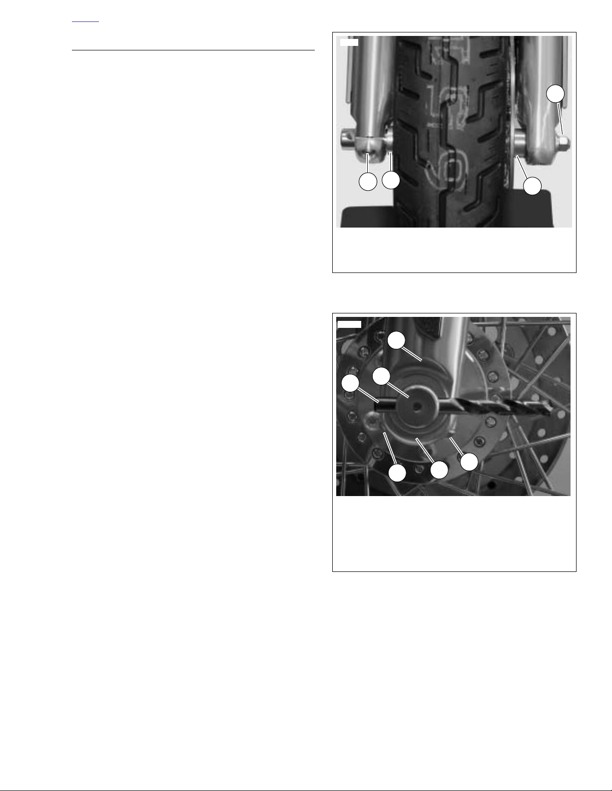
HOME
1. Spacer (2)
2. Axle nut, lockwasher and washer
3. Slider cap screws
11330
2
1
1
3
12208
1. Fork slider
2. Axle
3. 7/16 in. Drill bit
4. Rear axle cap fastener
5. Axle cap
6. Front axle cap fastener
2
3
1
6
5
4
INSTALLATION
1. Apply a light coat of LOCTITE ANTI-SEIZE LUBRICANT
to the axle.
2. See Figure 2-7. Place wheel into front fork and install
axle. Verify that axle spacers (1) on right and left side are
properly installed.
3. Install the washer, lockwasher, and slider cap screws.
Tighten axle nut to 50-55 ft-lbs (67.8-74.6 Nm). Hold axle
stationary with a steel rod or screwdriver inserted
through hole on right end of axle while tightening.
4. See Figure 2-8.
a. Loosen axle cap fasteners.
b. Insert 7/16 in. drill bit (2) as far as it will go into hole
in axle (1).
c. Position fork leg against edge of drill bit. Contact
point must the have edge of drill bit touching the
edge of fork leg.
Figure 2-7. Front Axle Assembly
Figure 2-8. Fork Alignment
2006 Dyna: Chassis 2-9
Page 68
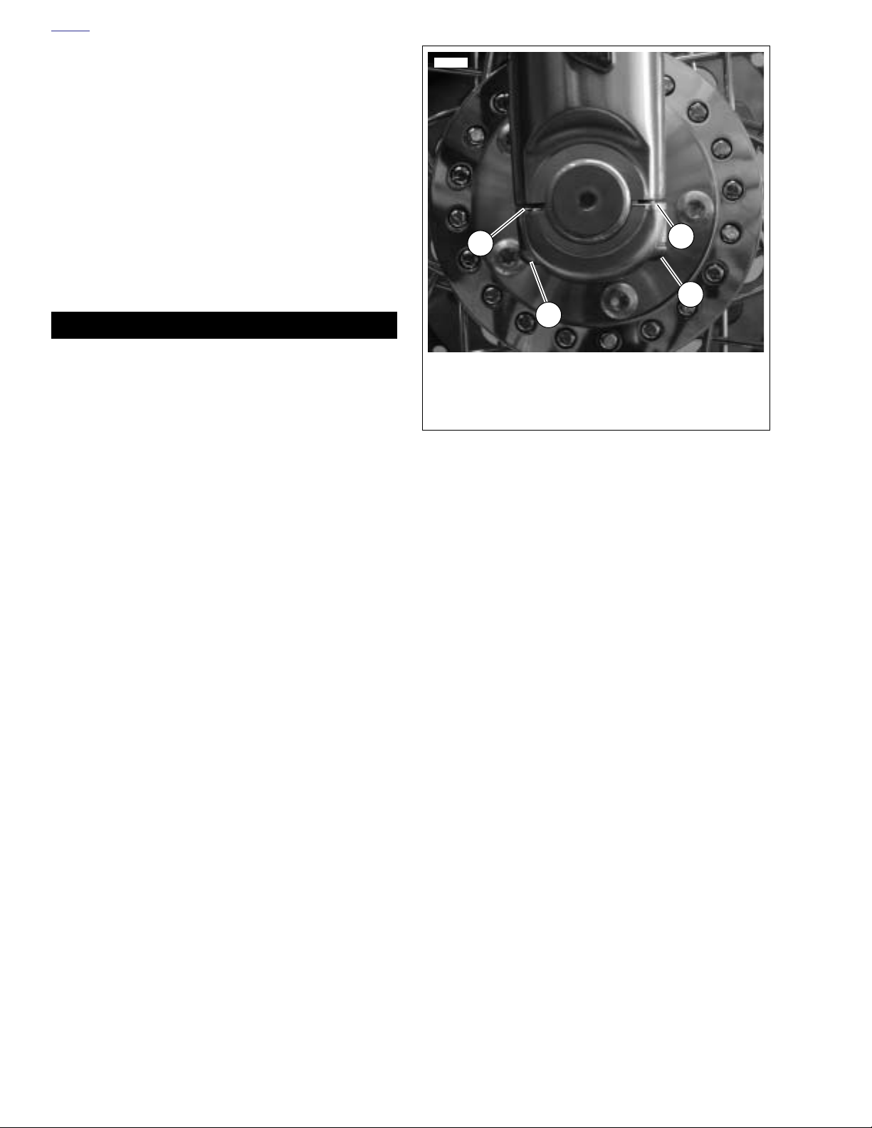
HOME
d. See Figure 2-9. With cast in spacer (1) of axle cap
facing rear of vehicle, tighten rear axle cap fastener
(2) to 12 ft-lbs (16.3 Nm) while holding slider against
7/16 drill bit if necessary.
e. While holding slider against 7/16 drill bit if neces-
sary, tighten front axle cap fastener to 12 ft-lbs (16.3
Nm). Remove drill bit.
5. See Figure 2-3. Install the brake caliper to the fork legs.
a. Loosely install long mounting bolt (1) (12 pt/10 mm)
into top hole on fork leg.
b. Install short mounting bolt (2) (12 pt/10 mm) into
bottom hole on fork leg. Tighten bottom mounting
bolt to 28-38 ft-lbs (38.0-51.5 Nm).
c. Final tighten the top mounting bolt to 28-38 ft-lbs
(38.0-51.5 Nm).
11WARNING1WARNING
Whenever a wheel is installed and before moving the
motorcycle, pump brakes to build brake system pressure. Insufficient pressure can adversely affect brake
performance, which could result in death or serious
injury. (00284a)
6. Pump brake hand lever to move pistons out until they
contact both brake pads. Verify piston location against
pads.
12206
1
2
1. Cast in spacer
2. Rear axle cap fastener
3. Front axle cap fastener
4. gap
Figure 2-9. Axle cap
4
3
2-10 2006 Dyna: Chassis
Page 69
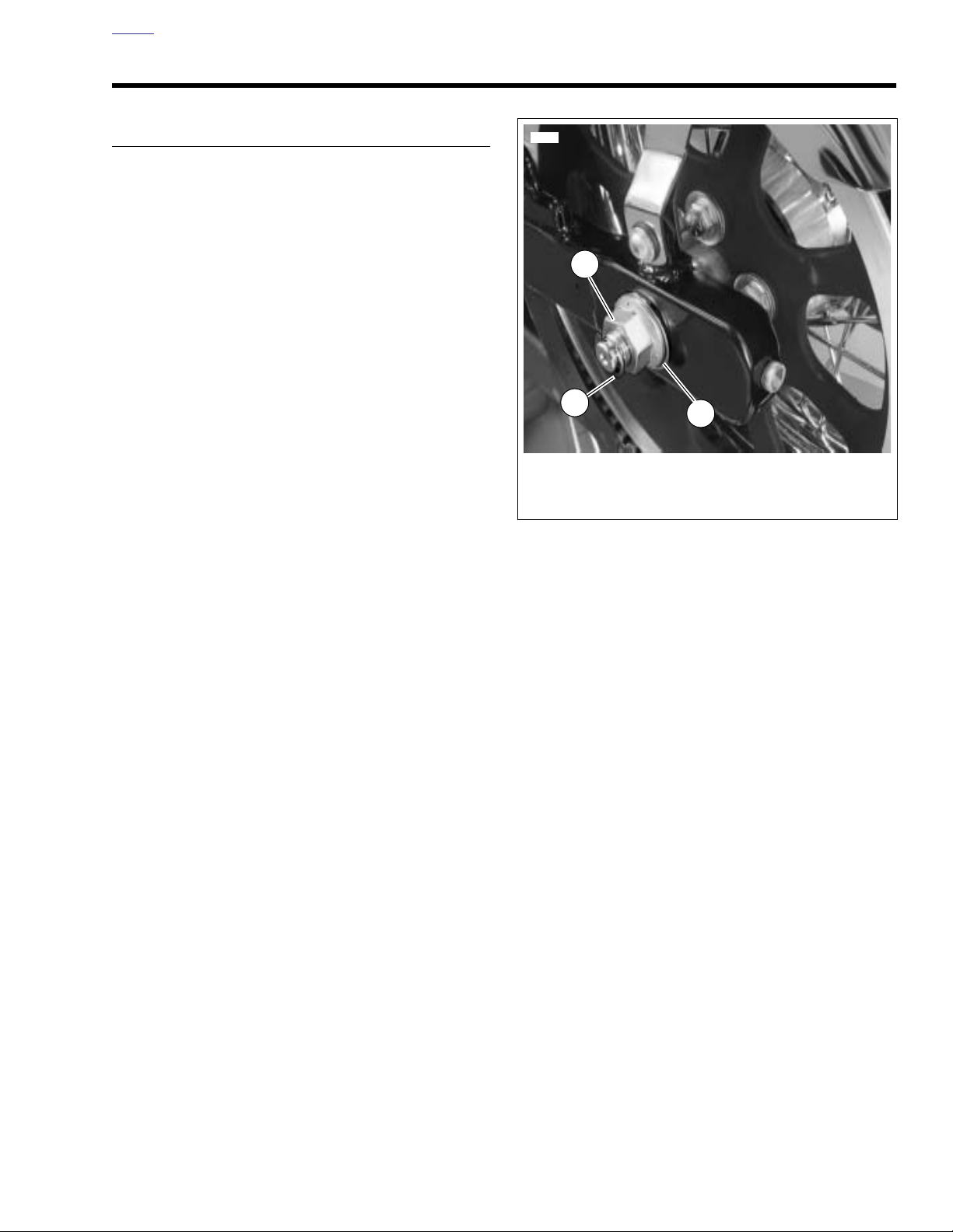
HOME
1. Retaining ring
2. Axle nut
3. Washer
11324
1
2
3
REAR WHEEL 2.5
REMOVAL
1. Block motorcycle underneath frame so rear wheel is
raised off the ground.
2. Remove three screws to detach the debris deflector from
rear fork. See 2.23 DEBRIS DEFLECTOR.
3. Inspect wheel bearing end play and service bearings if
necessary. See 2.6 SEALED WHEEL BEARINGS.
4. See Figure 2-10. Remove retaining ring (1), axle nut (2),
and washer (3) from left side of axle.
5. See Figure 2-11. Loosen, but do not remove, left and
right
upper
mounting screws (1).
6. Remove left and right
7. Allow rear fork and wheel to lower.
8. Remove belt guard. See 2.22 BELT GUARD.
9. Pry brake pads away from rotor.
10. Remove retaining pins and brake pads. See 1.8 BRAKE
PADS AND DISCS.
Caliper to rear wheel clearance is minimal. To prevent damage to surfaces, be careful when removing caliper from rear
fork.
11. Remove caliper assembly from rear fork. See 2.17 REAR
BRAKE CALIPER in this section.
12. Remove axle from wheel.
13. Move wheel forward and slip belt off sprocket.
Tension may have to be relieved before belt will slip off.
Spacer may fall out when tension is relieved.
14. Pull wheel and belt sprocket from rear fork.
Do not operate rear brake pedal with the rear wheel removed
or the caliper piston may be forced out of piston bores.
Reseating the piston requires disassembly of the caliper.
lower
shock mounting screws (2).
NOTE
NOTE
NOTE
Figure 2-10. Rear Axle
2006 Dyna: Chassis 2-11
Page 70
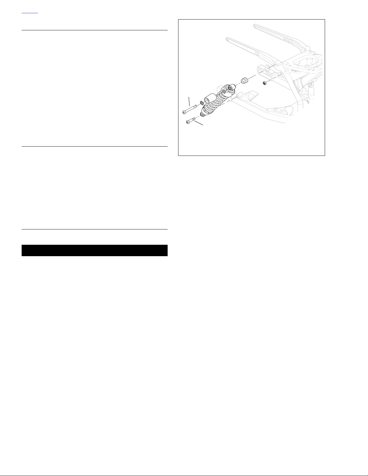
HOME
DISASSEMBLY
NOTE
With the exception of the sprocket cover (13), component
parts for cast and laced rear wheels are identical.
1. See Figure 2-12. Remove spacers (2, 11) from left and
right sides.
2. If necessary, remove brake disc and/or rear sprocket.
Label components so they may be installed in their original locations.
a. On left side of wheel, remove five screws (15) and
washers (16) to detach rear sprocket (9).
b. On right side of wheel, remove five screws (3) to
remove rear brake disc (4).
ASSEMBLY
1. If hub and rim were disassembled, see 2.7 WHEEL LAC-
ING: 17 IN. RIM, 2.8 WHEEL LACING: 19 IN. RIM, or 2.9
WHEEL LACING: 21 IN. RIM.
2. See Figure 2-12. Install brake disc (4) on valve stem side
of wheel if removed.
a. Apply a drop of LOCTITE THREADLOCKER 243
(blue) to the five screws (3).
b. Tighten to 30-45 ft-lbs (40.7-61.0 Nm).
d0797x2x
1
2
1. Upper mounting screws (2)
2. Lower mounting screws (2)
Figure 2-11. Rear Shock Mount
CLEANING AND INSPECTION
1. Inspect all parts for damage or excessive wear.
11WARNING1WARNING
Always replace brake pads in complete sets for correct
and safe brake operation. Improper brake operation
could result in death or serious injury. (00111a)
2. Inspect brake rotor and pads. See 1.8 BRAKE PADS
AND DISCS.
3. Inspect rear belt and sprocket. 1.15 REAR BELT AND
SPROCKETS.
4. Install belt sprocket (9) if removed.
a. Apply two drops of LOCTITE THREADLOCKER 262
(red) to the five screws (15). Install sprocket using
screws (15) and washers (16).
b. Tighten screws to 55-60 ft-lbs (74.6-81.3 Nm).
5. Install spacers (2, 10) into hub with largest chamfered
end facing away from wheel.
6. Verify that wheel and tire are true.
a. For laced wheels, see 2.10 TRUING LACED
WHEEL.
b. For cast wheels, see 2.11 CAST WHEEL RUNOUT.
2-12 2006 Dyna: Chassis
Page 71
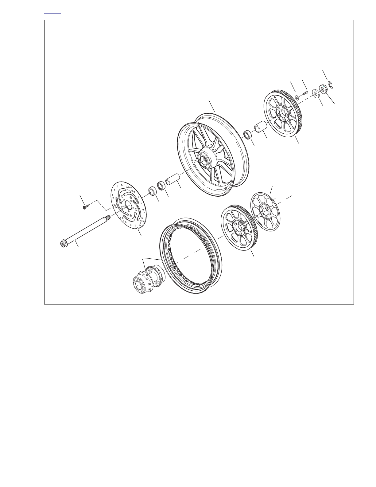
HOME
1. Axle
2. Right bearing spacer
3. Screw (5)
4. Rear brake disc
5. Bearing (2)
6. Sleeve
7. Cast wheel
8. Laced wheel hub and rim
9. Rear sprocket
10. Left bearing spacer
11. Washer
12. Axle nut
13. Sprocket cover (FXD35 only)
14. Retaining
15. Screw (5)
16. Washer (5)
14
15
16
7
12
11
10
5
9
13
3
6
5
2
4
1
8
9
d0452a2x
Figure 2-12. Rear Wheel/Hub
2006 Dyna: Chassis 2-13
Page 72

HOME
INSTALLATION
1. Roll wheel into rear fork and position brake disc side
spacer between wheel and fork.
2. Slide drive belt over drive sprocket. Make sure brake disc
is centered between brake pads.
3. Coat axle with LOCTITE ANTI-SEIZE LUBRICANT and
install.
a. From right side, carefully insert axle through right
rear fork, rear caliper bracket, right side spacer and
brake disc.
b. Continue sliding axle through wheel hub sleeve,
sprocket, left side spacer and left rear fork.
NOTE
Caliper to rear wheel clearance is minimal. To prevent damage to surfaces, be careful when removing caliper from rear
fork.
4. Install caliper assembly to rear fork. See 2.17 REAR
BRAKE CALIPER in this section.
5. Install brake pads and retaining pins. See 1.8 BRAKE
PADS AND DISCS.
6. See Figure 2-11. Attach rear shocks.
a. Apply two or three drops of LOCTITE THREAD-
LOCKER 243 (blue) to threads of lower shock
mounting screws (2).
b. Lift rear fork and install both shock absorbers with
lower shock mounting screws (2)
c. Tighten upper shock fasteners to 75-85 ft-lbs (101.7-
115.2 Nm).
d. Tighten lower shock fasteners to 30-40 ft-lbs (40.7-
54.2 Nm).
11WARNING1WARNING
Check wheel bearing end play after tightening axle nut to
specified torque. Excessive end play can adversely affect
stability and handling. Insufficient end play can cause
bearing seizure. Either condition can cause loss of control, which could result in death or serious injury.
(00285a)
7. See Figure 2-10. Install washer (3) and axle nut (2) on
left side of axle.
a. Tighten axle nut to 60-65 ft-lbs (81.3-88.1 Nm).
b. Install retaining ring (1).
8. Install debris deflector using three screws. Tighten to 4060
in-lbs
(4.5-6.8 Nm). See 2.23 DEBRIS DEFLECTOR.
9. Install belt guard. See 2.22 BELT GUARD.
11WARNING1WARNING
Whenever a wheel is installed and before moving the
motorcycle, pump brakes to build brake system pressure. Insufficient pressure can adversely affect brake
performance, which could result in death or serious
injury. (00284a)
10. Pump brake pedal to move pistons out until they contact
both brake pads. Verify piston location against pads.
11. Verify correct axle alignment (2.13 VEHICLE ALIGN-
MENT) and then check belt deflection (1.14 REAR BELT
DEFLECTION).
2-14 2006 Dyna: Chassis
Page 73
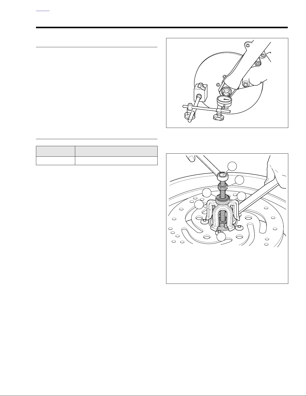
HOME
d0606x2x
1. Forcing screw
2. Nut
3. Washer
4. Nice bearing
5. Bridge
6. Collet with ball bearing inside
d0559x2x
1
2
4
6
5
3
SEALED WHEEL BEARINGS 2.6
INSPECTION
1. Block motorcycle underneath frame so wheel is raised
off the ground.
2. See Figure 2-13. Mount a magnetic base dial indicator to
the brake disc with the dial’s contact point on the end of
the axle.
3. Turn the wheel through several rotations, then move the
wheel side to side to check for end play.
a. If the end play is less than the service wear limit of
0.002 in. (0.051 mm), bearing passes inspection.
b. If end play exceeds service wear limit or feels rough,
remove wheel and replace both wheel bearings.
REMOVAL
PART NO.
HD-44060 Wheel bearing installer/remover
1. Remove wheel from motorcycle. See 2.4 FRONT
WHEEL or 2.5 REAR WHEEL as appropriate. If present,
remove hub plate from wheel on opposite side of front
brake disc.
2. See Figure 2-14. Obtain WHEEL BEARING INSTALLER/
REMOVER (Part No. HD-44060) and assemble.
a. Sparingly apply graphite lubricant to threads of forc-
ing screw (1) to prolong service life and ensure
smooth operation.
b. Install nut (2), washer (3) and Nice bearing (4) on
screw. Insert assembly through hole in bridge (5).
c. Drop ball bearing inside collet (6). Fasten collet and
ball bearing to forcing screw (1).
SPECIALTY TOOL
Figure 2-13. Wheel Bearing Inspection
(Front Wheel Shown)
Figure 2-14. Removal Tool
2006 Dyna: Chassis 2-15
Page 74
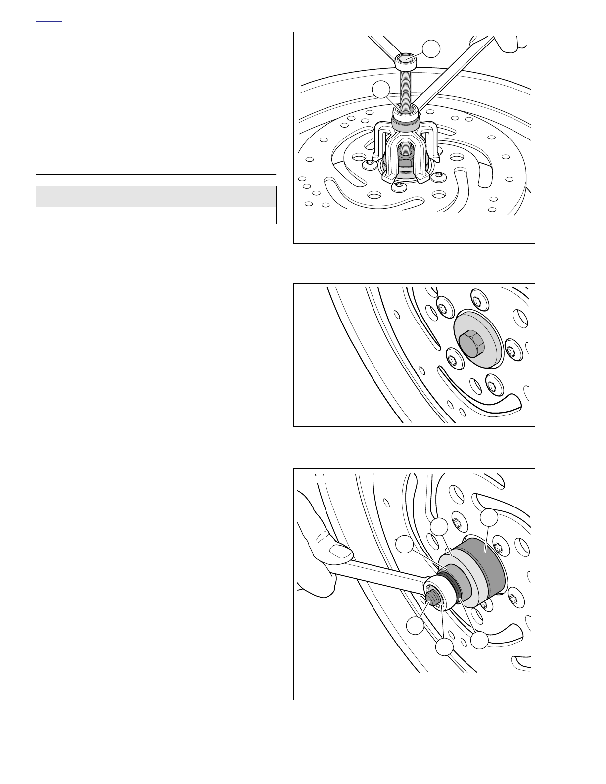
HOME
3. Hold end of forcing screw (1) and turn collet (6) to
expand edges of collet.
4. See Figure 2-15. When expanded collet has gripped
bearing edges, hold end of forcing screw (1) and turn the
nut (2) to remove bearing from wheel.
5. Remove spacer from inside wheel hub.
6. Repeat procedure for opposite side bearing. Discard all
bearings upon removal.
INSTALLATION
PART NO.
HD-44060 Wheel bearing installer/remover
Always install first bearing on primary brake disc side. If front
wheel has two brake discs, install bearing on the left side first.
1. Obtain WHEEL BEARING INSTALLER/REMOVER (Part
No. HD-44060) and assemble.
a. Sparingly apply graphite lubricant to threads of
threaded rod to prolong service life and ensure
smooth operation.
b. See Figure 2-16. Place threaded rod through sup-
port plate. Insert assembly through wheel.
c. See Figure 2-17. Place the
(1) with lettered side facing away from wheel centerline.
d. Install pilot (5), Nice bearing (4), washer (3) and nut
(2) over rod.
2. Hold hex end of threaded rod (1) and turn nut (2) to
install bearing (6). Bearing will be fully seated when nut
can no longer be turned. Remove tool.
3. Install spacer inside wheel hub.
4. Reverse tool and install opposite side bearing.
SPECIALTY TOOL
NOTE
new
bearing (6) on rod
d0560x2x
1
2
1. Forcing screw
2. Nut
Figure 2-15. Remove Bearing
d0561x2x
Figure 2-16. Installation Tool Support Plate
d0562x2x
2-16 2006 Dyna: Chassis
1. Threaded rod
2. Nut
3. Washer
4. Nice bearing
5. Pilot
6. Wheel bearing
Figure 2-17. Installing Bearing
5
6
4
1
2
3
Page 75
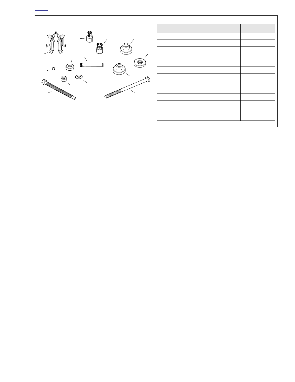
HOME
d0563x2x
8
7
1
6
9
2
4
5
3
Parts 1-7 common to removal/installation.
Parts 8-9 used for removal only.
Parts 10-13 used for installation only.
Figure 2-18. Wheel Bearing Remover/Installer (Part No. HD-44060)
11
10
13
NO. DESCRIPTION PA RT NO.
1Bridge HD-44060-5
2 Steel ball 12547
12
3Forcing screw HD-44060-4
4 Nut 10210
5Washer 12004
6 Nice bearing RS25100-200
7 Lubricant J-23444A
8 Collet, 3/4 in. (FXDWG only) HD-44060-3
9 Collet, 1.0 in. HD-44060-7
10 Pilot, 1.0 in. HD-44060-8
11 Pilot, 3/4 in. (FXDWG only) HD-44060-6
12 Support plate HD-44060-1
13 Threaded rod 280856
2006 Dyna: Chassis 2-17
Page 76
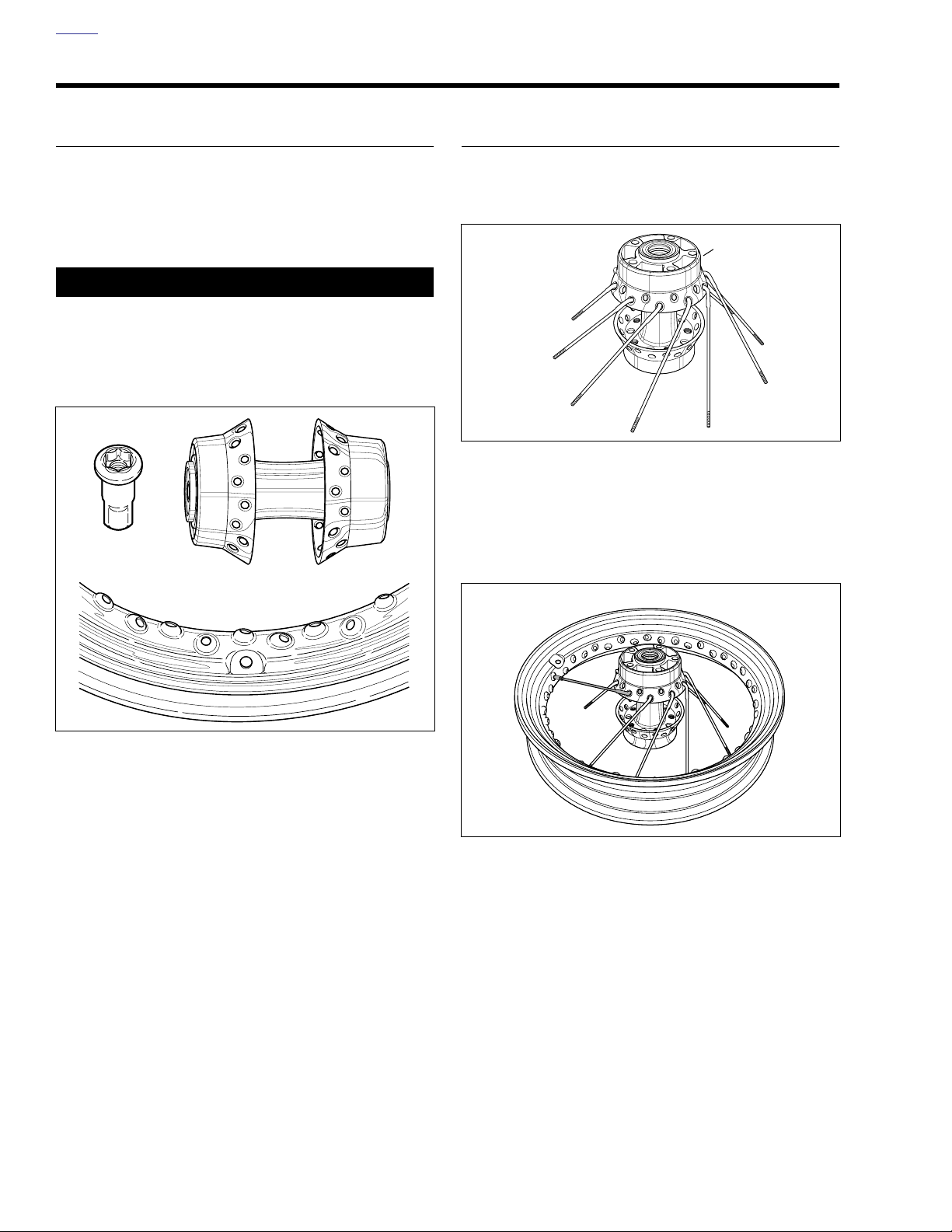
HOME
WHEEL LACING: 17 IN. RIM 2.7
GENERAL
NOTE
If only rim is to be replaced, tape spokes together to hold
position on hub and remove spokes from rim. Install taped
hub/spoke assembly to new rim and tighten spokes. Then
remove tape and true wheels.
11WARNING1WARNING
Avoid using oils that attack or contribute to the deterioration of rubber materials. Use of unsuitable oils may lead
to premature tire failure, which could result in death or
serious injury.
d0459x2x
PROCEDURE
1. Place the hub on table with brake disc side (narrow
flange) up. Insert a spoke in each hole of the
as shown below. Angle spokes clockwise.
d0456x2x
Figure 2-20.
2. Center the rim over the hub assembly with the valve
stem hole facing upward.
3. Using any
rim hole to the left of the valve stem hole on the upper
half of the rim centerline.
lower
row spoke, place the first spoke into the
Narrow flange
lower
row
Figure 2-19.
d0457x2x
Figure 2-21.
2-18 2006 Dyna: Chassis
Page 77
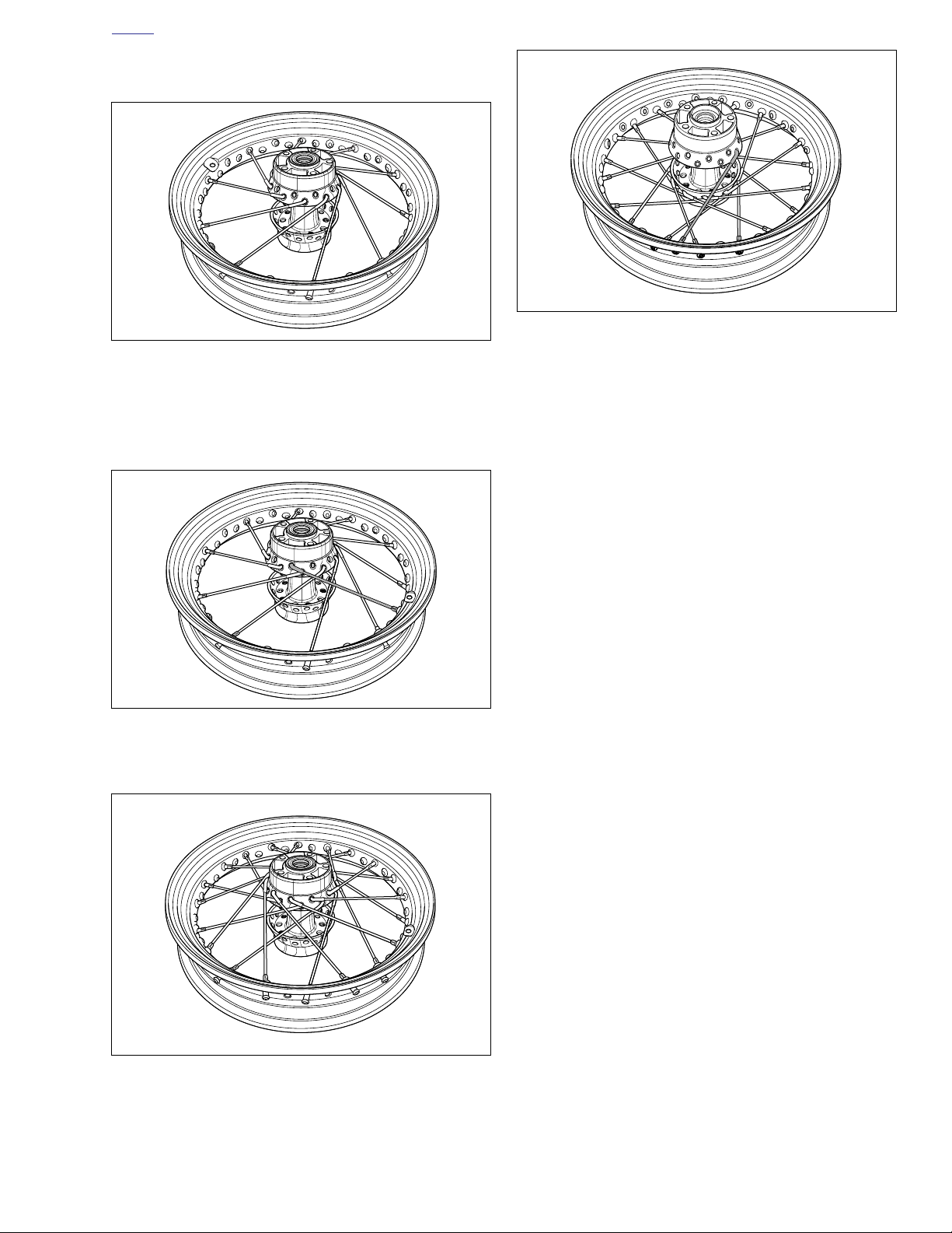
HOME
d0463x2x
4. Install the rest of lower row spokes in every fourth hole.
d0458x2x
Figure 2-22.
Figure 2-25.
5. Place the first
upper
row spoke into the hub as shown
below. Angle the spoke counterclockwise crossing four
lower row spokes. The spoke must enter the hole to the
left of the valve stem hole.
d0461x2x
Figure 2-23.
6. Install the remaining nine upper row spokes into every
fourth remaining hole above the rim centerline.
d0462x2x
Figure 2-24.
7. Turn rim over so brake disc side (narrow flange) faces
down. Place any
lower
row spoke into hub. Angle spoke
clockwise and place into rim hole angled to accept it.
2006 Dyna: Chassis 2-19
Page 78
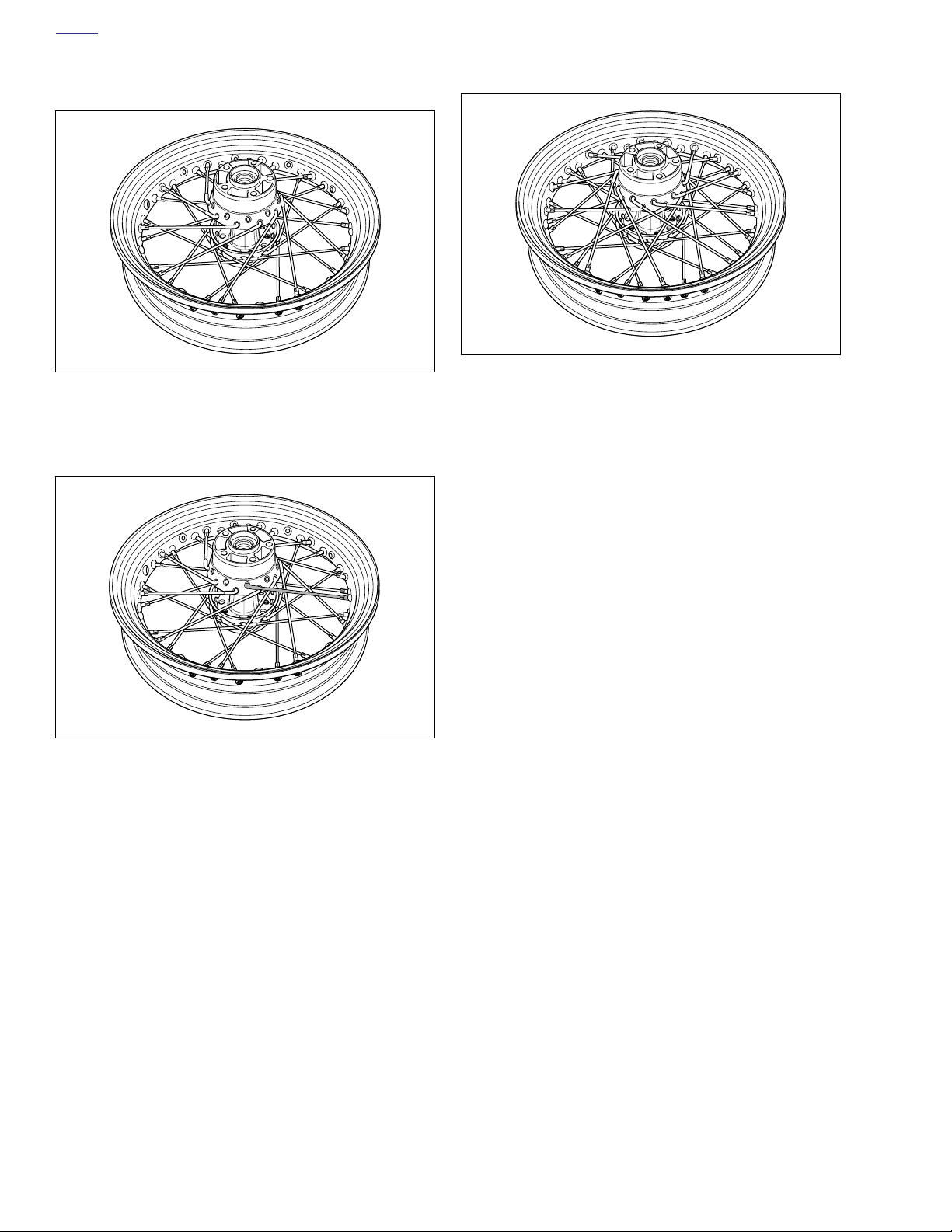
HOME
8. Place the remaining nine lower row spokes, angled
clockwise, into hub and rim.
d0464x2x
Figure 2-26.
9. Insert any
upper
row spoke into hub and angle spoke
counterclockwise. Place spoke into appropriate rim hole.
10. Install remaining nine upper row spokes.
d0466x2x
Figure 2-28.
11. Tighten spoke nipples to 55-65
in-lbs
(6.2-7.3 Nm).
12. True wheel. See 2.10 TRUING LACED WHEEL.
d0465x2x
Figure 2-27.
2-20 2006 Dyna: Chassis
Page 79
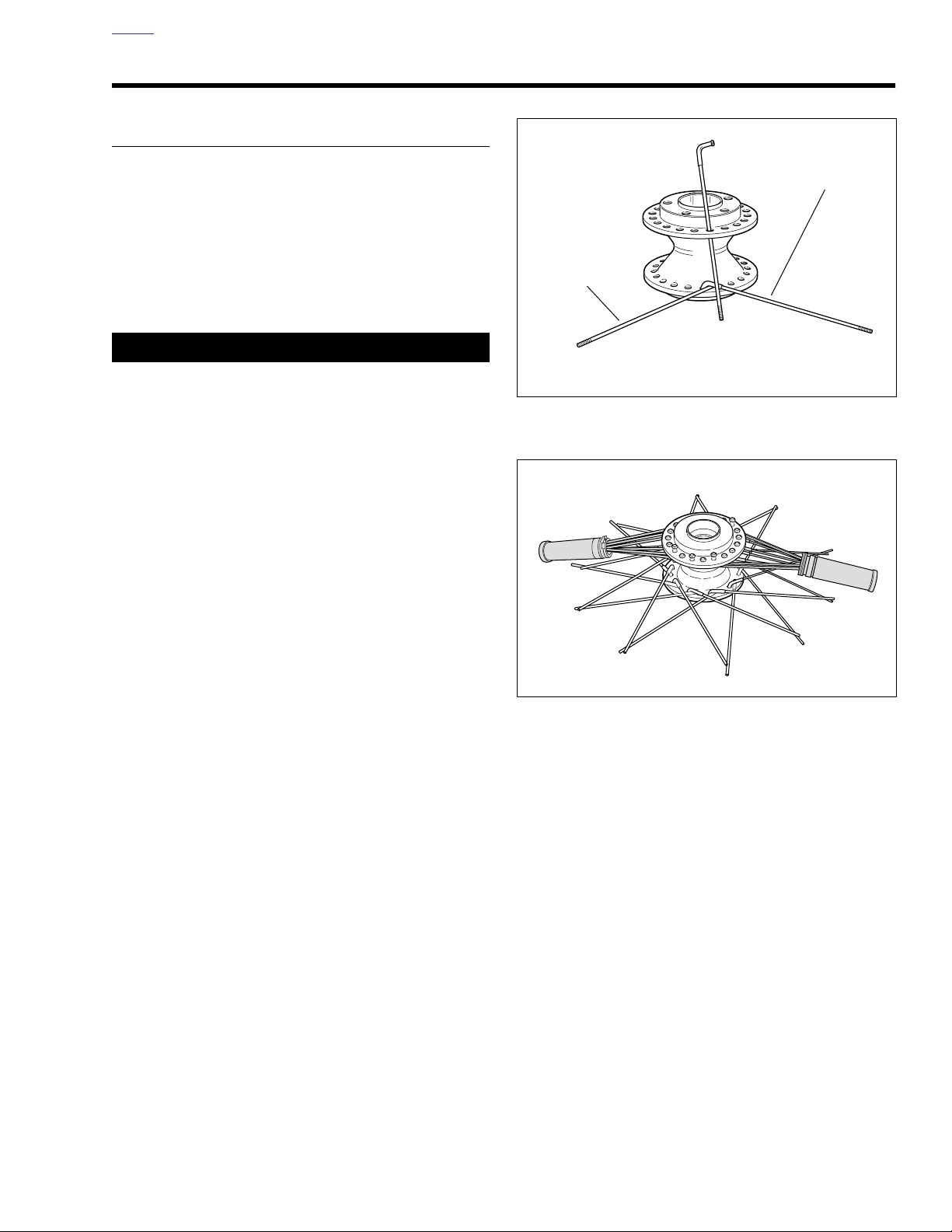
HOME
d0660x2x
1. Outer spoke (short head)
2. Inner spoke (long head)
1
2
d0661x2x
WHEEL LACING: 19 IN. RIM 2.8
PROCEDURE
NOTE
If only rim is to be replaced, tape spokes together to hold
position on hub and remove spokes from rim. Install taped
hub/spoke assembly to new rim and tighten spokes. Then
remove tape and true wheels.
1. Divide spokes into two groups.
a. Inner spokes have long heads.
b. Outer spokes have short heads.
11WARNING1WARNING
Avoid using oils that attack or contribute to the deterioration of rubber materials. Use of unsuitable oils may lead
to premature tire failure, which could result in death or
serious injury.
2. Lubricate spoke threads and nipple shoulders with tire
mounting lubricant.
3. See Figure 2-29. Place hub on bench with the brake disc
side up. On dual-disc wheel hubs, this is the side with the
cast recesses between the brake disc bolt holes. Insert
one outer spoke (short head) into any bottom flange hole
and swing it clockwise. Insert an inner spoke (long head)
in the next hole to the left of the outer spoke. Swing the
inner spoke counterclockwise over the outer spoke.
4. Find the hole in the upper flange directly above the two
spokes just inserted. This hole uses a long head inner
spoke. Insert inner spoke into the hole on the upper
flange that directly bisects the two spokes in the bottom
flange. Insert all remaining spokes in upper flange alternating the inner and outer spokes.
5. After one flange side is completed flip wheel hub upside
down and repeat to finish other flange.
6. See Figure 2-30. With all forty spokes inserted in hub,
group all spokes on top flange into two bundles. Secure
each group with throttle grips to keep the spokes
together.
Figure 2-29. Lacing 19-in. Wheel Hub
Figure 2-30. Bundling Top Spokes
2006 Dyna: Chassis 2-21
Page 80
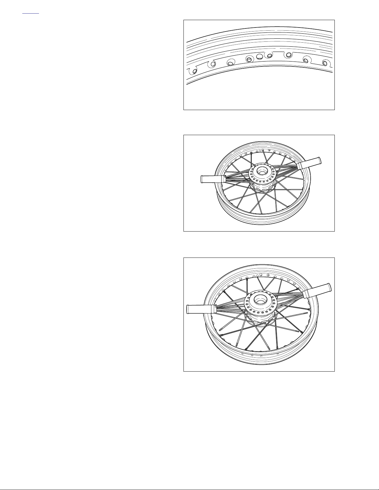
HOME
7. Swing all bottom flange outer spokes (short head) clockwise.
8. Swing the inner spokes (long head) counterclockwise,
crossing over the outer spokes (short head).
9. Angle all spokes as far as they will go without overlapping the next LIKE spoke. For instance, swing an inner
spoke (long head) counter clockwise across four spokes
as far as it will go before crossing another inner spoke
(laced in a cross-four pattern).
NOTES
All inside spokes lay over all outside spokes.
●
●
See Figure 2-31. The valve stem hole is centered of the
rim; you do not have to worry about choosing the correct
relationship between the rim and the hub.
10. Center the rim over the hub assembly.
NOTE:
It is recommended that you lace the first spoke next to the
valve stem hole. When lacing your first spoke, place spoke
nipples through several rim holes to determine the correct
lacing direction. Only one spoke will fit into the spoke nipple
correctly. When connecting the spoke to the spoke nipple, finger tighten two to three threads.
11. Straighten any spokes that were accidentally bumped or
moved on the bottom flange.
12. Work with the bottom flange of outer spokes (short head)
first.
13. See Figure 2-32. Using the spoke alignment method discussed previously, Locate a hole pointing downward and
outward toward the bottom flange of outer spokes (short
head).
a. Verify outer spoke (short head) reaches the spoke
nipple and secure spoke loosely by hand. Skip three
rim holes and repeat lacing. Follow pattern to complete bottom flange outer spokes (short head).
b. See Figure 2-33. Once you have completed lacing
the bottom row of outer spokes (short head) double
check for three empty holes in between each spoke.
d0662x2x
Figure 2-31. Valve Stem Hole Location
d0663x2x
Figure 2-32. Beginning Spoke: Bottom Flange Outer
d0664x2x
2-22 2006 Dyna: Chassis
Figure 2-33. Completed Spokes: Bottom Flange Outer
Page 81
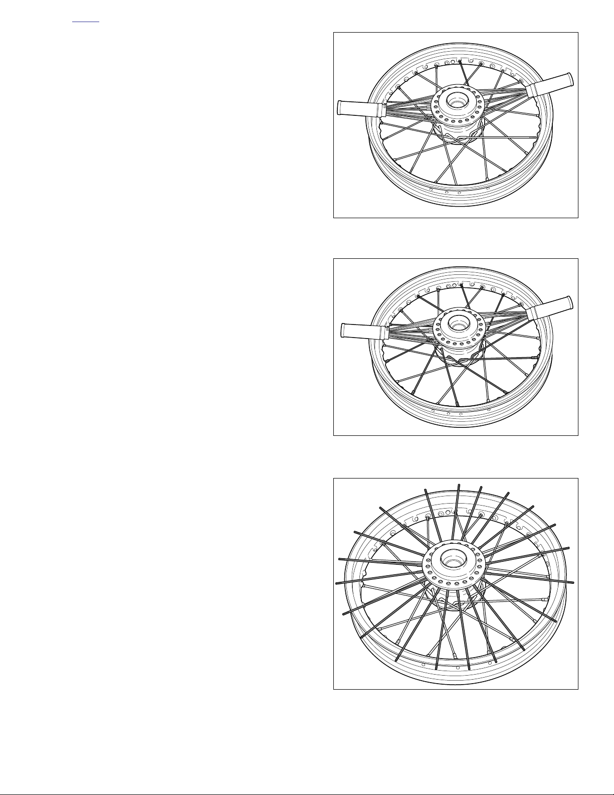
HOME
14. Work with bottom flange inner spokes (long head) next.
Choose a beginning spoke closest to the valve stem
hole.
a. See Figure 2-34. Each inner spoke (long head)
crosses four outer spokes (short head).
b. See Figure 2-35. Ver ify inner spoke reaches spoke
nipple and secure spoke loosely by hand. Skip every
other hole and repeat lacing. Follow pattern to complete bottom row inner spokes (long head).
15. See Figure 2-36. Undo each top bundle and fan the
spokes out (in a starburst pattern) around the top rim
edge.
d0665x2x
Figure 2-34. Beginning Spoke: Bottom Flange Inner
d0674x2x
Figure 2-35. Completed Spokes: Bottom Flange Inner
d0667x2x
Figure 2-36. Fanning Top Flange Spokes
2006 Dyna: Chassis 2-23
Page 82
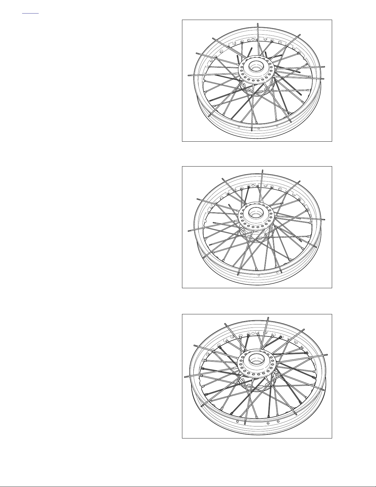
HOME
16. See Figure 2-37. Point all the top flange inner spokes
(long head) clockwise one at a time leaving the outer
spokes (short head) resting on the rim.
NOTE
Do not knock outer spokes (short head) under inner spokes
(long head) or they will be trapped underneath the inner row
of spokes.
17. Using the spoke alignment method discussed previously,
choose a beginning spoke closest to the valve stem hole.
Start with top flange inner spokes (long head) first.
a. See Figure 2-38. Verify spoke reaches spoke nipple
and secure spoke by hand. Follow pattern to complete top flange inner spokes (long head).
b. See Figure 2-39. Once you have completed the top
flange of inner spokes (long head) double check for
one empty hole after every third spoke.
d0668x2x
Figure 2-37. Setting Top Flange Inner Spokes
d0669x2x
Figure 2-38. Beginning Spoke: Top Flange Inner
d0670x2x
Figure 2-39. Completed Spokes: Top Flange Inner
2-24 2006 Dyna: Chassis
Page 83
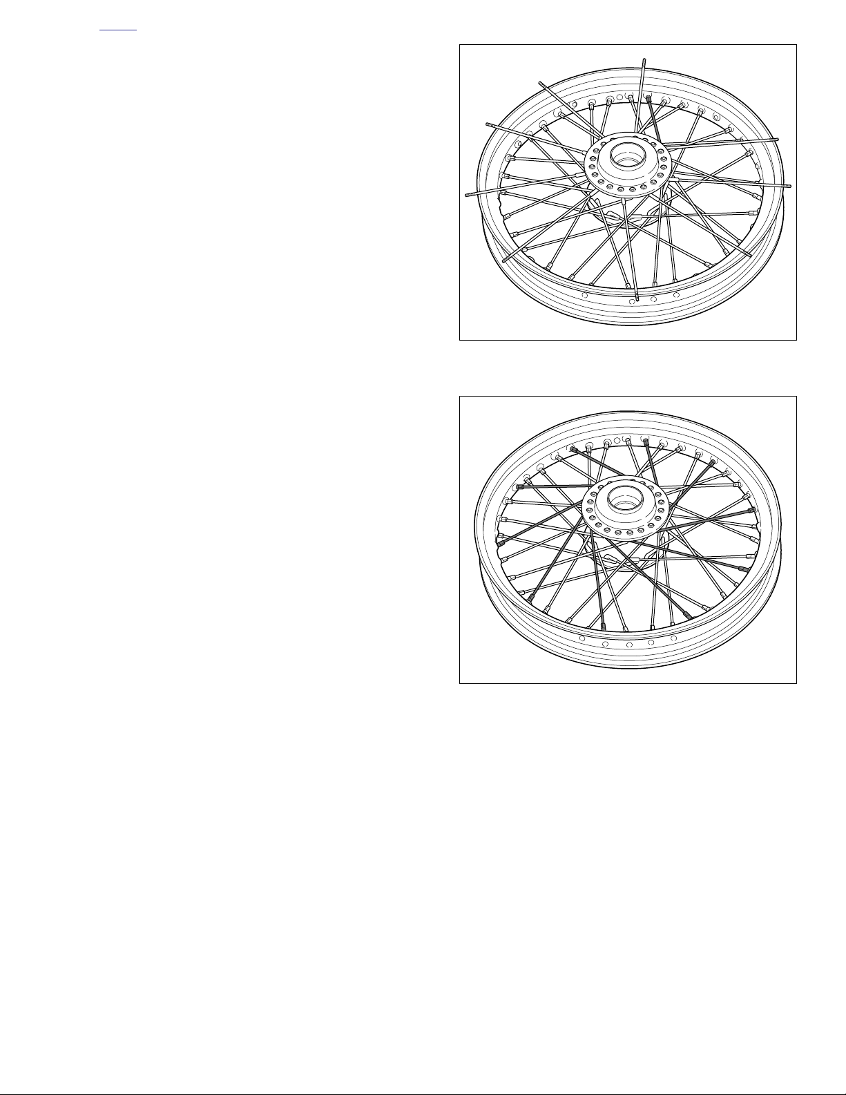
HOME
d0672x2x
18. See Figure 2-40. Finish with top flange outer spokes
(short head). Point the top flange outer spokes (short
head) counterclockwise and make sure each one
crosses four inner spokes before securing it to the rim.
19. See Figure 2-41. Verify spoke reaches spoke nipple and
secure spoke by hand. Follow pattern to complete top
flange outer spokes (short head).
20. Tighten spoke nipples to 55-65
in-lbs
(6.2-7.3 Nm).
21. True the wheel. See TRUING LACED WHEEL.
d0671x2x
Figure 2-40. Beginning Spoke: Top Flange Outer
Figure 2-41. Completed Spokes: Top Flange Outer
2006 Dyna: Chassis 2-25
Page 84
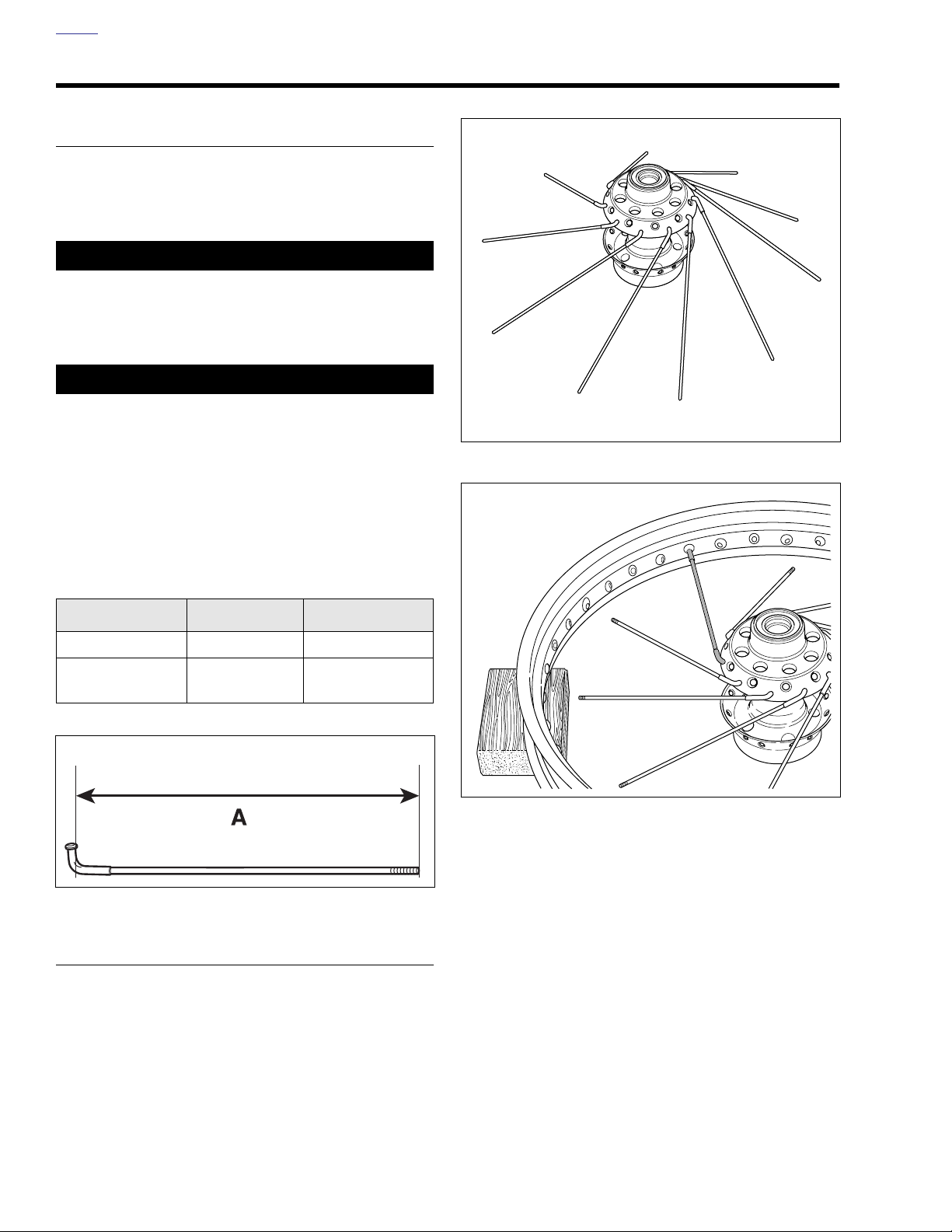
HOME
WHEEL LACING: 21 IN. RIM 2.9
GENERAL
If only rim is to be replaced, tape spokes together to hold
position on hub and remove spokes from rim. Install taped
hub/spoke assembly to new rim and tighten spokes. Then
remove tape and true wheels.
11WARNING1WARNING
Avoid using oils that attack or contribute to the deterioration of rubber materials. Use of unsuitable oils may lead
to premature tire failure, which could result in death or
serious injury.
CAUTION
Do not install incorrect spokes on rim. Steel laced rims
use zinc plated spokes. Chrome aluminum profile laced
rims use chrome plated spokes.
NOTE
Steel laced rims use
profile laced rims use
See Figure 2-42. Measure distance “A” to determine spoke
length.
zinc
plated spokes. Chrome aluminum
chrome
plated spokes.
d0467x2x
Figure 2-43.
d0468x2x
Table 2-3. 21 In. Rim Spoke Length
Rim
Steel laced 9.42-9.46 239.3-240.3
Chrome aluminum
profile laced
d0759x2x
Figure 2-42. Spoke Length
IN. MM.
9.52-9.56 241.8-242.8
PROCEDURE
1. See Figure 2-43. Place the hub on table with brake disc
side (wide flange) down. Insert a spoke in each hole of
the
lower
row as shown below. Angle spokes clockwise.
Figure 2-44.
2. Center the rim over the hub assembly with the valve
stem hole facing upward.
3. See Figure 2-44. Using any
first spoke into the rim hole, angled to correctly accept
the spoke, on the upper half of the rim centerline.
2-26 2006 Dyna: Chassis
lower
row spoke, place the
Page 85
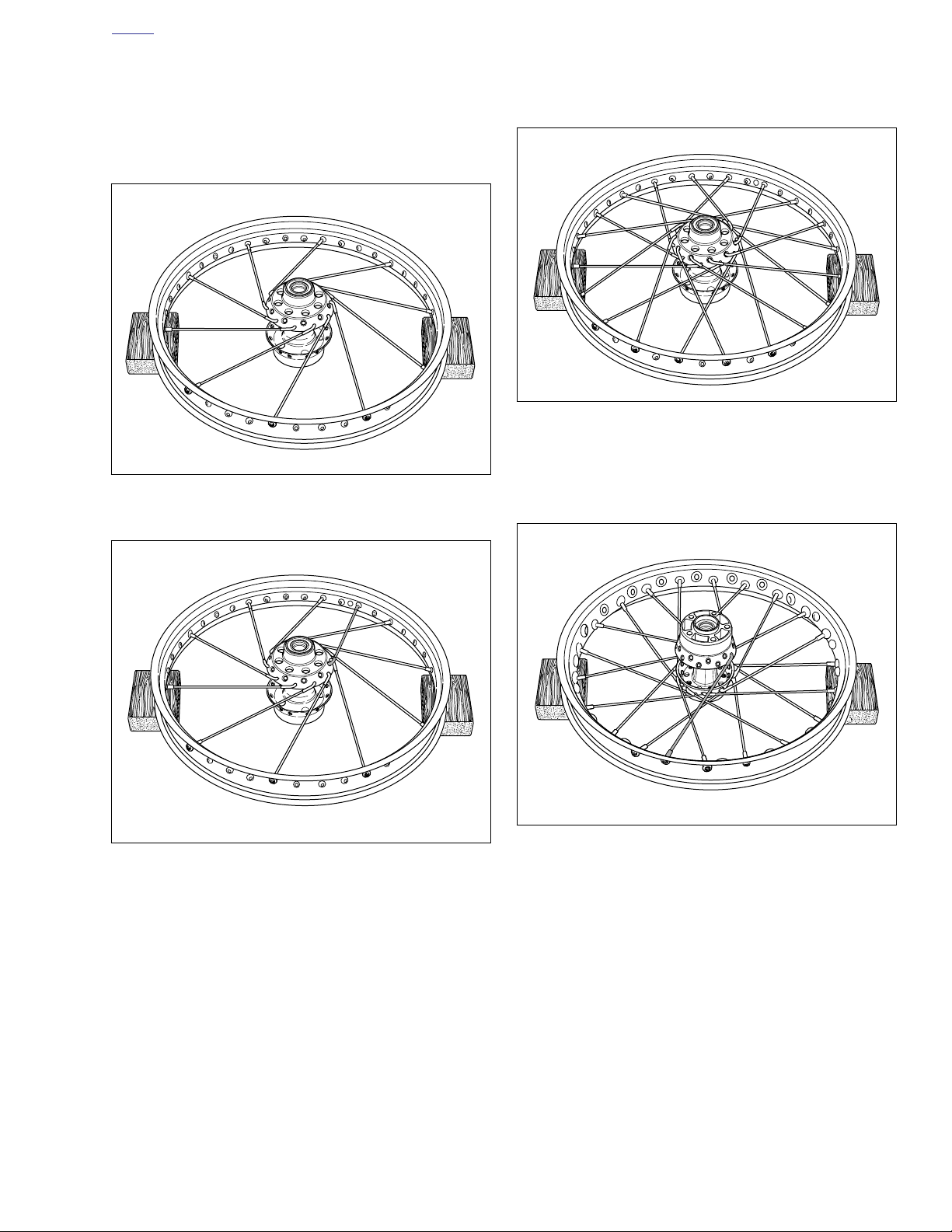
HOME
d0471x2x
d0472x2x
4. See Figure 2-45. Install the rest of lower row spokes in
every fourth hole.
5. See Figure 2-46. Place the first
upper
row spoke into the
hub as shown below. Angle the spoke counterclockwise
crossing four lower row spokes. The spoke must enter
the hole to the right of the valve stem hole.
d0469x2x
Figure 2-45.
6. See Figure 2-47. Install the remaining nine upper row
spokes into every fourth remaining hole above the rim
centerline. This completes spoke installation on this side.
Figure 2-47.
7. See Figure 2-48. Tu rn rim over, brake disc side up. Place
any
lower
row spoke into hub. Angle spoke clockwise
and place into rim hole angled to accept it.
d0470x2x
Figure 2-48.
Figure 2-46.
2006 Dyna: Chassis 2-27
Page 86
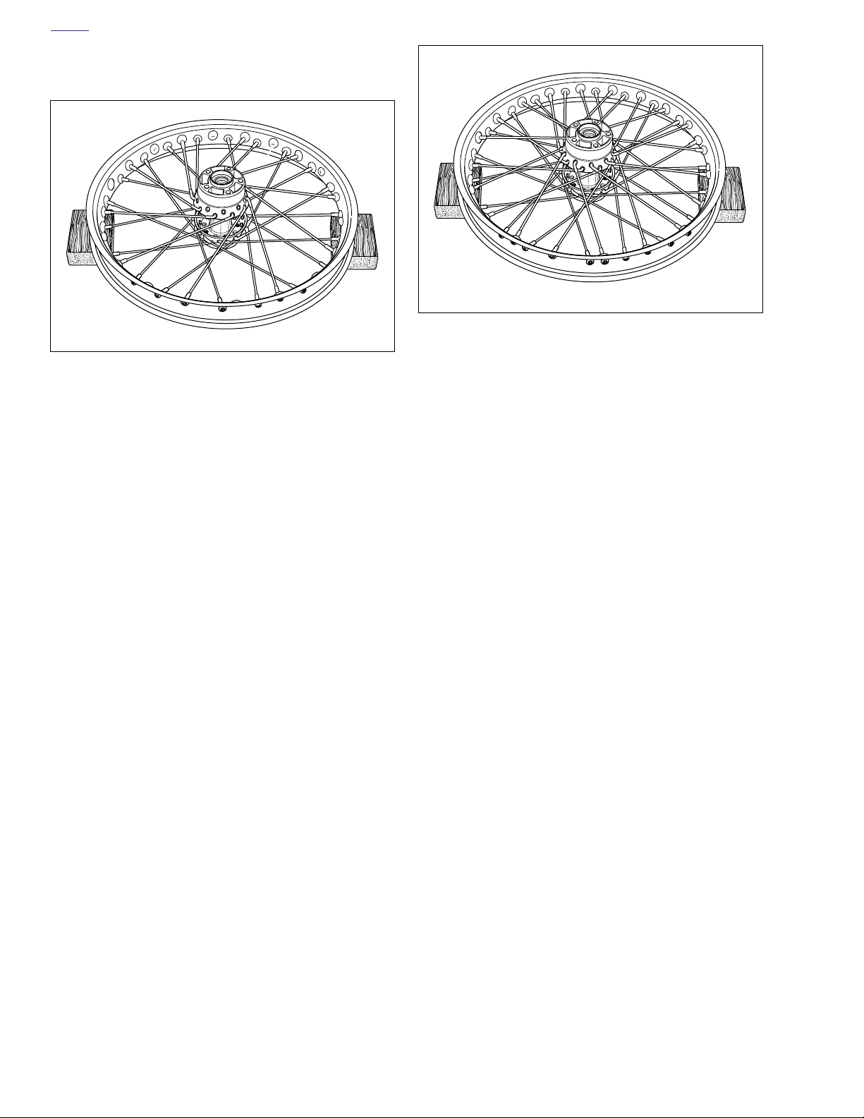
HOME
8. See Figure 2-49. Place the remaining nine lower row
spokes, angled clockwise, into hub and rim.
d0473x2x
Figure 2-49.
9. See Figure 2-50. Insert any
upper
row spoke into hub
and angle spoke counterclockwise into appropriate rim
hole. Install remaining upper row spokes.
d0474x2x
Figure 2-50.
10. Tighten spoke nipples to 55-65
in-lbs
(6.2-7.3 Nm).
11. True wheel. See 2.10 TRUING LACED WHEEL.
2-28 2006 Dyna: Chassis
Page 87
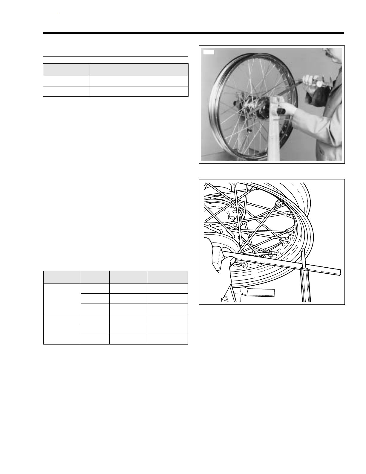
HOME
7473
d0475x2x
TRUING LACED WHEEL 2.10
GENERAL
PART NO. SPECIALTY TOOL
HD-99500-80 Wheel truing stand
HD-94681-80 Spoke wrench
The rim must be trued both laterally and radially. If new bear-
ings were installed, wheels may be trued with only the bearings and center spacer installed.
LATERAL TRUING
1. Divide the wheel spokes into ten groups of four and mark
the center of each group with a piece of tape. The groups
should be directly across from one another and approximately 90 degrees apart. Tighten the spokes in these
four groups finger tight, leaving all others loose.
2. See Figure 2-52. Install truing arbor in wheel hub and
place wheel in WHEEL TRUING STAND (Part No. HD99500-80). Tighten arbor nuts so hub will turn on its
bearings.
3. Lay a straightedge across hub brake disc flange and one
of the marked spoke groups. Measure distance “A” from
the straightedge to the location shown in Figure 2-53.
NOTE
The offset dimension, distance “A”, must be as listed in Ta bl e
2-4.
Figure 8-51. Front Wheel Hub Offset Dimension
Table 2-4. Offset Dimensions
RIM TYPE RIM SIZE IN. MM.
21 1.530-1.550 38.86-39.37
Steel laced
Chrome
aluminum
profile laced
4. If the dimension is not correct, tighten the four spokes
accordingly. Use SPOKE WRENCH (Part No. HD-94681-
80). For example, If the measurement on the right rim
edge side is less than it should be, loosen the two
spokes attached to the hub right side and tighten the
two spokes attached to the hub left side. Turn all four
spokes an equal number of turns until offset dimension is
correct.
Always loosen the appropriate spokes before tightening the
other two. Reversing this procedure will cause the rim to
become out-of-round.
5. Repeat the previous step for all four groups on the wheel.
19 1.140-1.160 28.95-29.46
17 0.620-0.640 15.75-16.26
21 1.560-1.580 39.62-40.13
19 0.890-0.910 22.68-23.19
17 0.390-0.410 9.90-10.41
NOTE
Figure 2-52. Rear Wheel Hub Offset Dimension
2006 Dyna: Chassis 2-29
Page 88
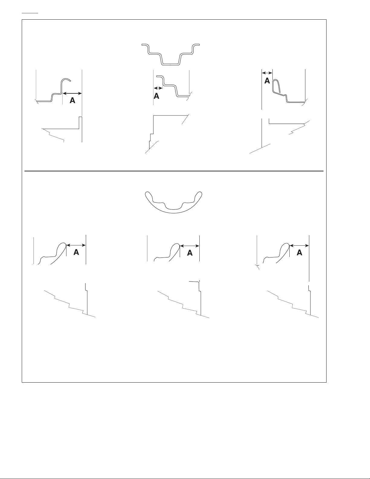
HOME
d0476b2x
Steel laced rim
Offset:
0.390-0.410 in.
Hub on 17 in. rear
spoke - all models
Offset:
0.390-0.410 in.
Hub on 17 in. rear
spoke - all models
Offset: 1.140-1.160 in.
on 19 in. front spoke all but FXDWG
Chrome aluminum
profile laced rim
Offset:
0.890-0.910 in.
Hub on 19 in. front
spoke - all but FXDWG
Offset: 1.530-1.550 in.
Hub on 21 in.
front spoke FXDWG
Offset: 1.560-1.580 in.
Hub on 21 in.
front spoke FXDWG
2-30 2006 Dyna: Chassis
Figure 2-53. Laced Hub Offset Dimension
Page 89
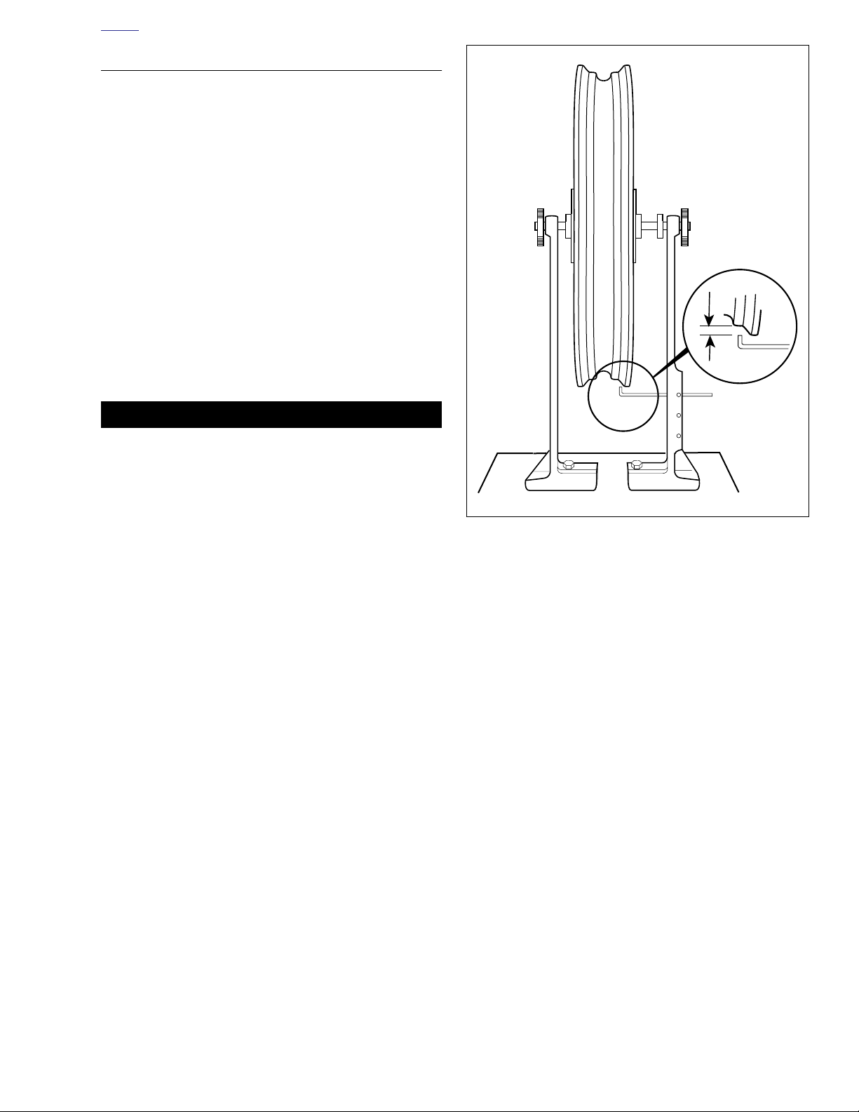
HOME
d0477x2x
RADIAL TRUING
1. See Figure 2-54. Adjust truing stand gauge to the rim’s
tire bead seat as shown. The rim should be trued within
0.031 in. (0.79 mm).
2. Spin the rim slowly. If the rim contacts the gauge on or
near a marked group of spokes, loosen the spokes in the
marked group on the opposite side of the rim. Now
tighten the spokes in the group where the rim makes
contact. Loosen and tighten spokes an equal number of
turns.
3. If the rim contacts the gauge between two marked
groups, loosen the spokes in both opposite groups and
tighten the spoke groups on the side of the rim that
makes contact.
4. When the wheel is centered and trued, start at the valve
hole and tighten the rest of the spoke nipples one turn at
a time until they are snug.
5. Seat each spoke head in the hub flange using a flat nose
punch and mallet. Then check wheel trueness again and
tighten the nipples accordingly.
CAUTION
Do not tighten spokes too tight, or nipples may be drawn
through rim, or hub flanges may be distorted. Tighten
spokes to 55-65 in-lbs (6.2-7.3 Nm). If spokes are left too
loose, they will continue to loosen when wheel is put into
service.
6. File or grind off ends of spokes protruding through nipples to prevent puncturing tube when tire is mounted.
NOTE
After installation of front wheel, visually check the relationship
of the front wheel to the fork fender bosses. The front wheel
should be approximately centered between the bosses.
Figure 2-54. Truing Rim Radially
2006 Dyna: Chassis 2-31
Page 90
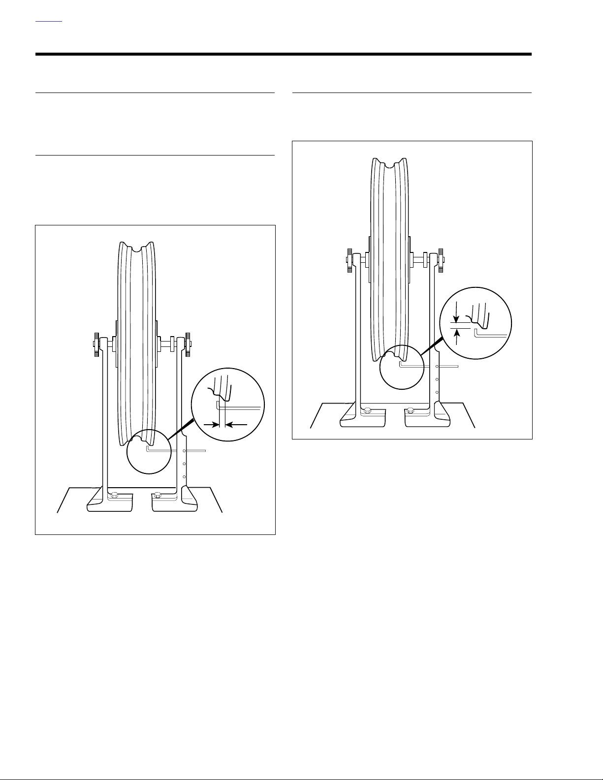
HOME
CAST WHEEL RUNOUT 2.11
GENERAL
The die-cast wheels should be checked for lateral and radial
runout before installing a new tire or tube.
LATERAL RUNOUT
See Figure 2-55. Install arbor in the wheel hub and place
wheel in the truing stand. To check rim lateral runout, place a
gauge rod or dial indicator near the rim bead. If lateral runout
exceeds 0.040 in. (1.02 mm), replace the wheel.
d0478x2x
RADIAL RUNOUT
See Figure 2-56. Check for radial runout as shown. Replace
the wheel if runout exceeds 0.030 in. (0.76 mm).
d0477x2x
Figure 2-55. Checking Lateral Runout
Figure 2-56. Checking Radial Runout
2-32 2006 Dyna: Chassis
Page 91
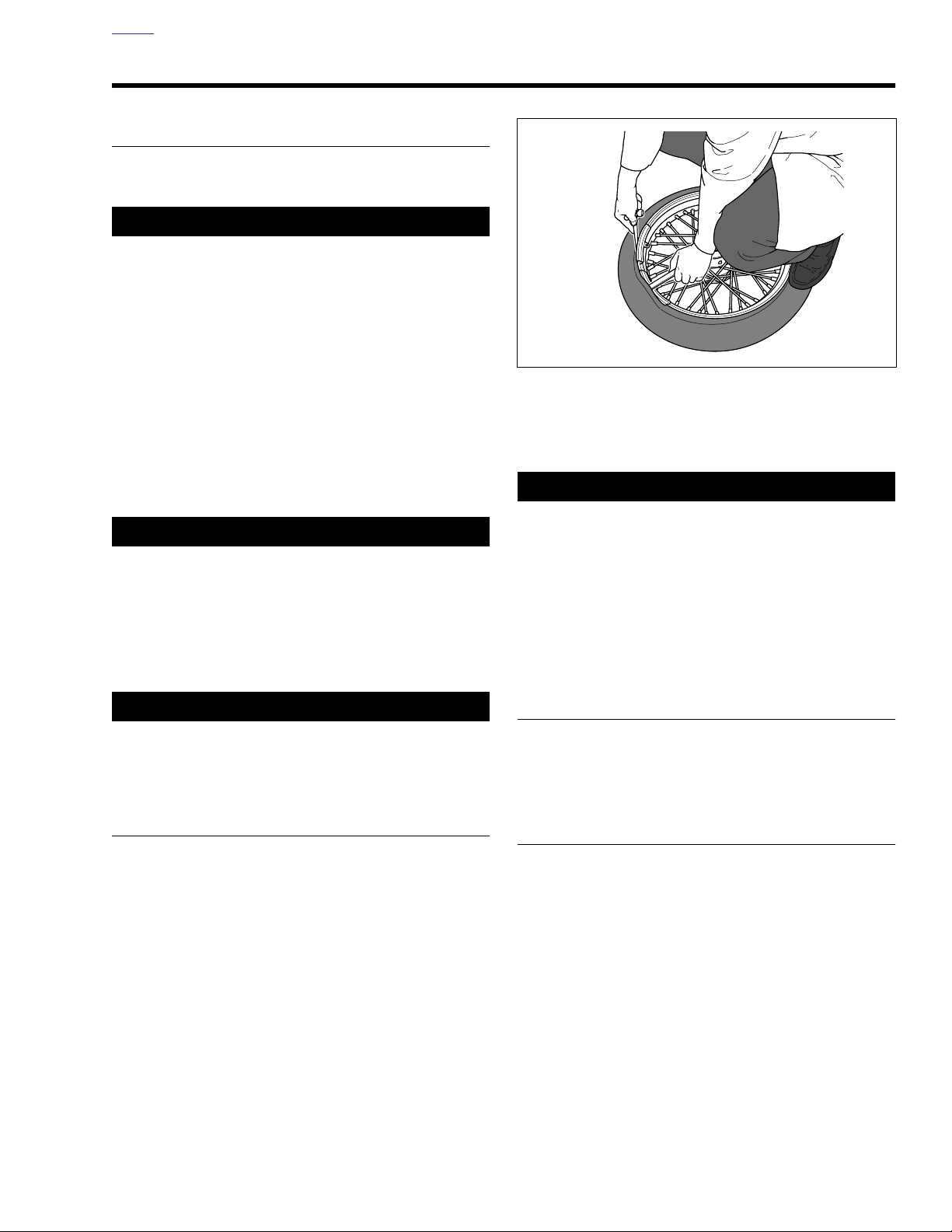
HOME
CAUTION
d0607x2x
TIRES 2.12
GENERAL
Tires should be inspected for punctures, cuts, breaks and
wear at least weekly.
11WARNING1WARNING
Replace punctured or damaged tires. In some cases,
small punctures in the tread area may be repaired from
within the demounted tire by a Harley-Davidson dealer.
Speed should NOT exceed 50 mph (80 km/h) for the first
24 hours after repair, and the repaired tire should NEVER
be used over 80 mph (130 km/h). Failure to follow this
warning could result in death or serious injury. (00015a)
Tubeless tires may be repaired in the tread area only if the
puncture is 1/4 in. (6.4 mm) or smaller. All repairs must be
made from inside the tire.
Acceptable repair methods include a patch and plug combination, chemical or hot vulcanizing patches or head-type
plugs. When repairing tubeless tires, use TIRE SPREADER
(Part No. HD-21000) to spread the tire sidewalls.
11WARNING1WARNING
Harley-Davidson tires are equipped with wear bars that
run horizontally across the tread. When wear bars
become visible and only 1/32 in. (0.8 mm) tread depth
remains, replace tire immediately. Using a worn tire can
adversely affect stability and handling, which could
result in death or serious injury. Use only Dunlop HarleyDavidson replacement tires. (00090a)
It is not necessary to use tools to remove tubeless tires. Make
sure beads are well lubricated before removing from rim.
If tire tools are used, take care not to damage the tire and
rim sealing surfaces. Use RIM PROTECTORS (Part No.
HD-01289) to protect rims.
5. Push lower bead into rim well on one side and insert tire
tool underneath bead from opposite side. Pry bead over
rim edge. Remove tire from rim.
It is not always necessary to completely remove tire from rim.
Removing one side allows the tire to be inspected.
Figure 2-57. Starting Tire Off Rim
NOTE
NOTE
11WARNING1WARNING
Harley-Davidson front and rear tires are not the same.
Interchanging front and rear tires can cause tire failure,
which could result in death or serious injury. (00026a)
REMOVAL
1. Remove wheel from motorcycle.
2. Let the air out of the tire.
3. Loosen both tire beads from rim flange. In most cases, a
bead breaker machine will be required to loosen the
bead from the rim.
4. See Figure 2-57. Using tire tools (not sharp instruments),
and RIM PROTECTORS (Part No. HD-01289) start
upper bead over edge of rim at valve. Do not use excessive force when starting bead over rim. Bead wires may
be damaged ruining the tire. Repeat all around rim until
first bead is over rim.
CLEANING AND INSPECTION
1. Clean the inside of tire and rim.
2. If rim is dirty or rusty, clean with a stiff wire brush.
3. Inspect the tire for wear.
REPLACEMENT
Always replace tires when 1/32 inch (0.8 mm) or less of tire
tread remains, determined by the appearance of tire wear
indicator bars. See TIRE REPLACEMENT under 1.9 TIRES
AND WHEELS.
2006 Dyna: Chassis 2-33
Page 92
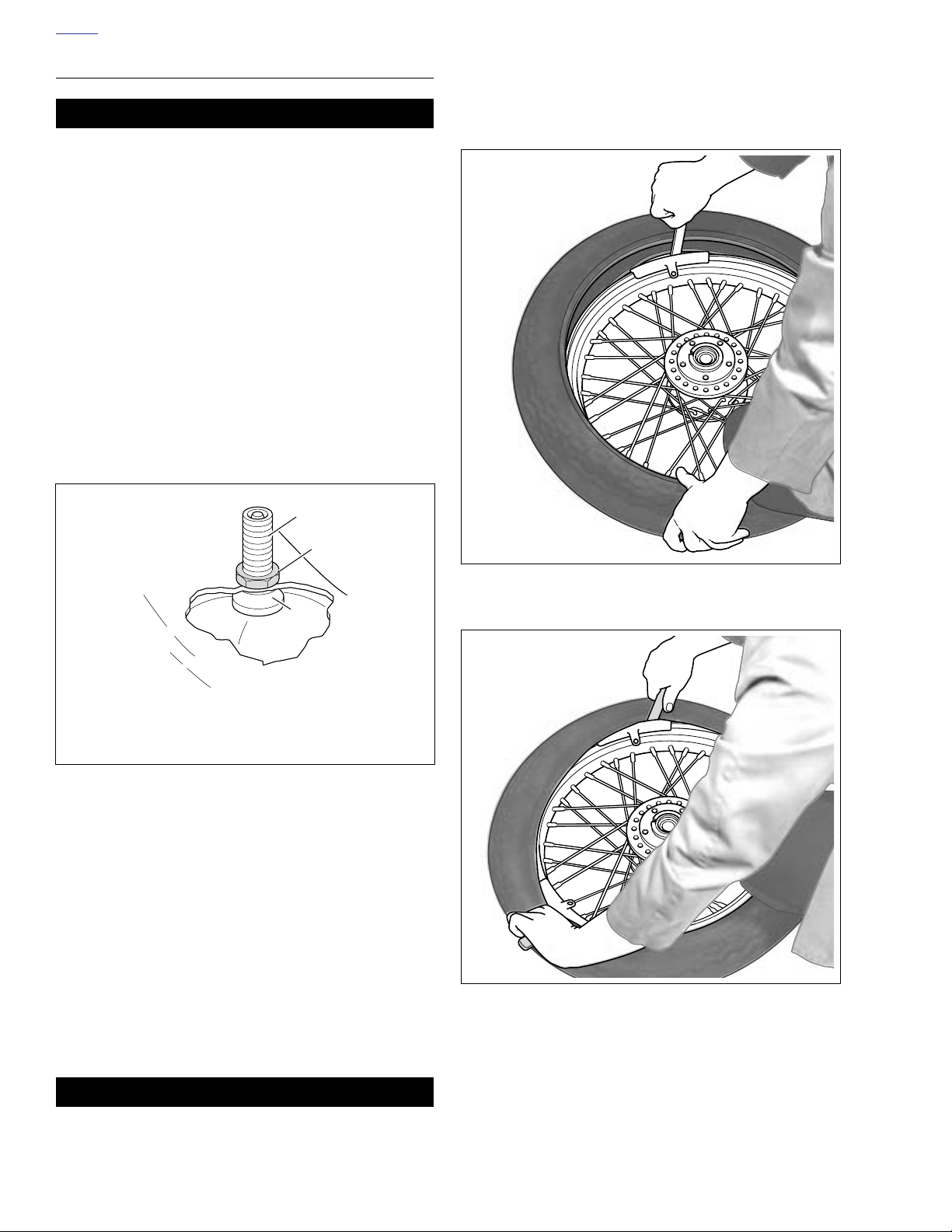
HOME
g
INSTALLATION
11WARNING1WARNING
● Use only Harley-Davidson approved tires. Using non-
approved tires can adversely affect stability, which
could result in death or serious injury. (00024a)
● Only install original equipment tire valves and valve
caps. A valve, or valve and cap combination, that is
too long or too heavy can strike adjacent components and damage the valve, causing rapid tire deflation. Rapid tire deflation can cause loss of vehicle
control, which could result in death or serious injury.
(00281a)
NOTE
Damaged or leaking valves must be replaced.
1. See Figure 2-58. Place rubber grommet (3) on valve
stem (1) with shoulder in recess of the valve stem head.
a. Insert valve stem center facing away from rim.
b. Install nut (2). Tighten to 12-15 in-lbs (1.4-1.7 Nm).
5. Inflate the tire to recommended pressure to seat the
bead. See 1.9 TIRES AND WHEELS.
6. Use BEAD EXPANDER (Part No. HD-28700) to seat
beads.
d0608x2x
d0521x2x
1
2
3
1. Valve stem
2. Nut on outside of rim
3. Rubber
2. Thoroughly lubricate the rim flanges and both beads of
the tire with tire lubricant. Install RIM PROTECTORS,
(Part No. HD-01289) to prevent scarring rims.
3. See Figure 2-59. Starting at the valve stem, start the first
bead into the rim well. Work the bead on as far as possible by hand. Use the tire tool to pry the remaining bead
over the rim flange. If tire has colored dot on sidewall, it is
a balance mark and should be located next to valve stem
hole.
4. See Figure 2-60. Starting 180 degrees from the valve
stem, start the second bead onto the rim. Work the bead
onto the rim with tire tools, working toward valve in both
directions. Remove the valve core from the rim hole
before prying the remaining bead over the rim flange.
rommet
Figure 2-58. Valve Stem
Figure 2-59. Starting Bead on Rim
d0609x2x
Figure 2-60. Starting Second Bead on Rim
11WARNING1WARNING
Do not exceed manufacturer's recommended pressure to
seat beads. Exceeding recommended bead seat pressure can cause tire rim assembly to burst, which could
result in death or serious injury. (00282a)
2-34 2006 Dyna: Chassis
Page 93
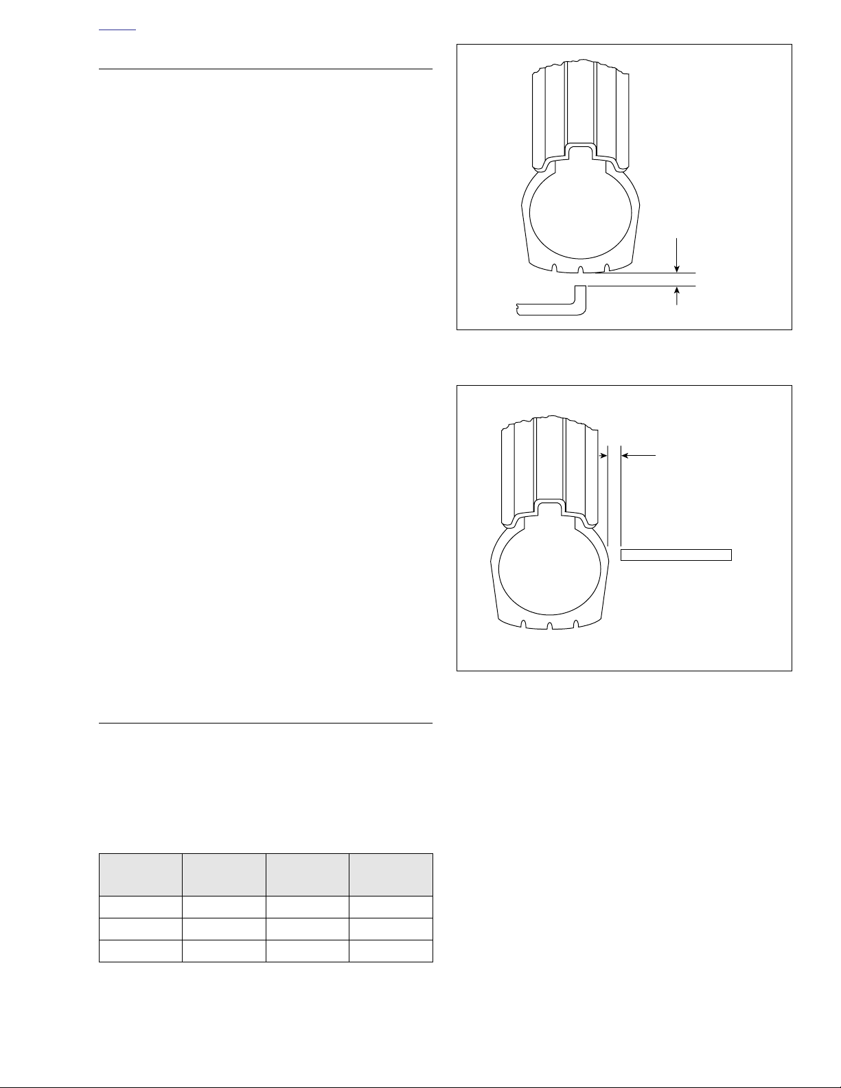
HOME
d0479x2x
d0480x2x
CHECKING TIRE RUNOUT
Radial Runout
1. See Figure 2-61. Check runout by turning wheel on axle,
measuring amount of radial displacement from a fixed
point near the tire.
2. Maximum tire tread runout is 0.090 in. (2.29 mm). If tire
tread runout exceeds 0.090 in. (2.29 mm), remove tire
from rim and check rim runout to see if rim is at fault. See
2.10 TRUING LACED WHEEL or 2.11 CAST WHEEL
RUNOUT.
NOTE
Make sure bead is properly seated on rim. Deflate and reseat
tire if necessary.
3. If rim runout is less than 0.031 in. (0.79 mm), tire is at
fault and should be replaced. If rim runout is more than
0.031 in. (0.79 mm), correct by replacing cast wheel or
truing laced wheel.
Lateral Runout
1. See Figure 2-62. Check runout by turning wheel on axle,
measuring tread runout.
2. Maximum tire tread runout is 0.080 in. (2.03 mm). If tire
tread runout exceeds 0.080 in. (2.03 mm), remove tire
from rim and check rim bead runout to see if rim is at
fault. See 2.10 TRUING LACED WHEEL or 2.11 CAST
WHEEL RUNOUT.
NOTE
Be sure bead is properly seated on rim. Deflate and reseat
tire if necessary.
3. If rim bead runout is less than 0.031 in. (0.79 mm), tire is
at fault and should be replaced. If rim bead runout is
more than 0.031 in. (0.79 mm), correct by replacing cast
wheel or truing laced wheel.
WHEEL BALANCING
Wheels must be balanced to improve handling and reduce
vibration, especially at high road speeds. Cast aluminum
wheels require special self-adhesive weights. Refer to Tabl e
2-5.
Table 2-5. Wheel Weights and Colors
WEIGHT
Gold yes yes no
Silver no yes yes
Black no no yes
1. Self adhesive wheel weights should be applied to the flat
surface of the rim. Be sure that application area is completely clean, dry and free of oil and grease.
1 oz.
(28 g)
0.5 oz
(14 g)
0.25 oz
(7 g)
Figure 2-61. Radial Tire Runout
Figure 2-62. Lateral Tire Runout
2. Remove paper backing from weight and apply 3 drops of
Loctite 420 (Superbonder) to the adhesive side of the
weight. Place the weight on the rim, press firmly in place
and hold for 10 seconds. Full adhesive cure takes 8
hours.
NOTE
If 1 oz. (28 g) or more weight must be added at one location,
split the amount so that half is applied to each side of the rim.
Wheel should not be used for 8 hours to allow adhesive to
cure completely.
3. In most cases, static balancing using WHEEL TRUING
STAND (Part No. HD-95500-80) will produce satisfactory
results. However, dynamic balancing, utilizing a wheel
spinner, should be used to produce finer tolerances for
best high and low speed handling characteristics. Follow
the instructions supplied with the balance machine you
are using. Wheels should be balanced to within 0.5 oz.
(14 g) at 60 MPH (97 km/h). The maximum permissible
weight to accomplish balance is 3.5 oz. (99 g) total.
2006 Dyna: Chassis 2-35
Page 94
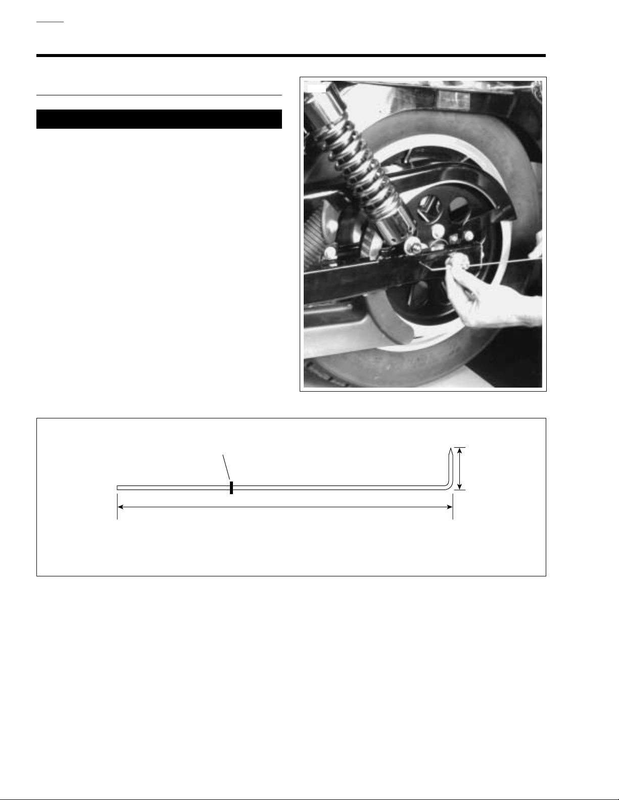
HOME
VEHICLE ALIGNMENT 2.13
INSPECTION
11WARNING1WARNING
Check vehicle alignment according to following procedures. Incorrect alignment can adversely affect stability
and handling, which could result in death or serious
injury. (00287a)
1. Verify wheels are true to specifications. See 2.10 TRUING
LACED WHEEL or 2.11 CAST WHEEL RUNOUT.
2. Check steering head bearing adjustment and adjust if
necessary. See 1.17 STEERING HEAD BEARINGS.
3. See Figure 2-64. To ensure accurate measurements,
obtain a piece of 1/8 in. (3.2 mm) aluminum welding rod
11 in. (280 mm) long. Grind one end down to a blunt
point. With a pliers, bend the rod 90 degrees as shown.
Place a snug fitting grommet on the rod to act as a slide
measurement indicator.
4. See Figure 2-63. With the blunt point of the alignment
tool inserted in the rear fork pilot hole, slide the rubber
grommet along the tool until it is aligned with the center
of the axle as shown. Repeat for the other side of the
motorcycle.
7477
d0482x2x
Figure 2-63. Measuring Alignment
Grommet
1.25 in.
(32 mm)
10.0 in.
(254 mm)
Figure 2-64. Alignment Tool
2-36 2006 Dyna: Chassis
Page 95
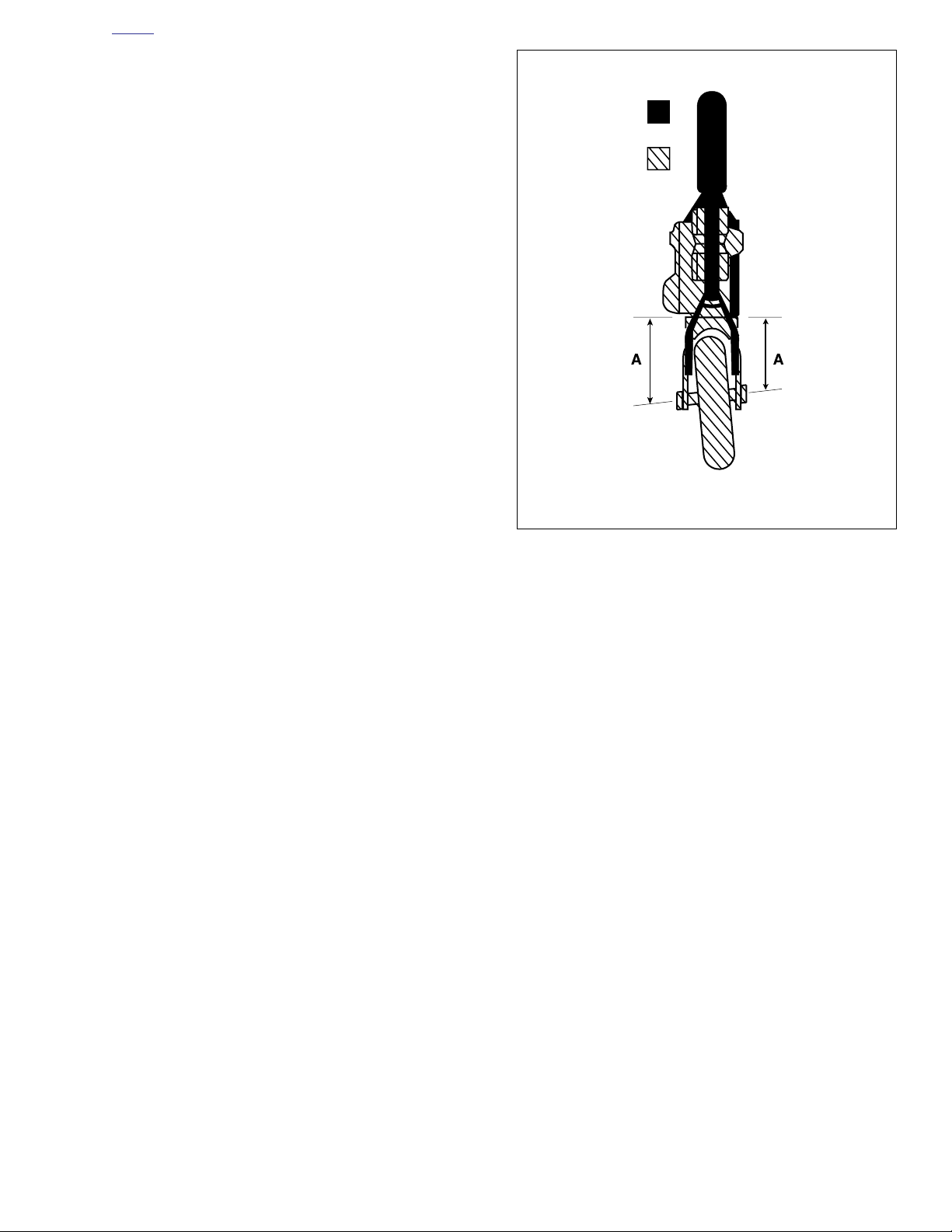
HOME
Chassis
Powertrain
Distance ‘A’ must be equal
Rear fork
hole
Rear axle
center
Correct by
adjusting belt
adjusters
d0481x2x
5. See Figure 2-65. The measurement between the center
of the rear axle and the rear fork hole must be equal to
within 1/32 in (0.8 mm). on both sides of the motorcycle.
If it is not, adjust the rear wheel with the axle adjusters to
accomplish the equal measurement. It is extremely
important that this adjustment be made as accurately as
possible in order to make the remaining adjustments
accurate.
6. Raise the rear of the motorcycle so that the rear wheel
spins freely. Do this by placing a center stand or blocking
under the frame.
7. See Figure 2-66. Remove the bolt (2) which attaches the
top stabilizer link (1) to the engine mounting bracket.
8. Position front wheel so brake disc is vertical using an
inclinometer. If possible, use a digital inclinometer for the
best accuracy.
NOTES
● The exhaust system must be in place while performing
the following steps.
● Motorcycle must be upright and level before performing
this procedure.
Figure 2-65. Rear Wheel Misaligned
2006 Dyna: Chassis 2-37
Page 96
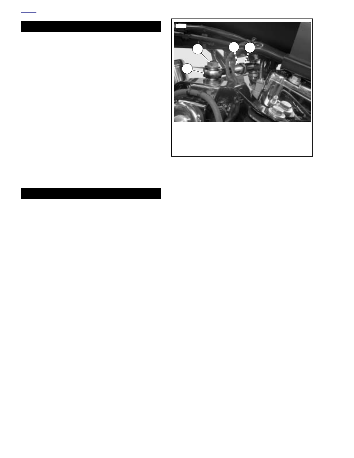
HOME
CAUTION
The Dyna Glide stabilizer link should only be loosened/
adjusted on one end. There is one end that has threads
showing. Adjust this end only. Do not loosen/adjust the
other end or the isolator will tear.
NOTE
There should be 0.25 in. (6.4 mm) minimum clearance
between the fuel tank tunnel and the head of the left stabilizer
link mounting bolt.
9. Loosen jam nut (3) on stabilizer link. Adjust the stabilizer
so that the bolt removed in step 7 can be reinstalled without pushing the engine to the right or left. Tighten jam
nut.
10. Check the rear brake disc with the inclinometer to ensure
that it is parallel to the front brake disc.
IF THE ABOVE STEPS DO NOT ALIGN VEHICLE:
11. If the rear brake disc is not parallel to the front brake disc,
adjust the top stabilizer link until the rear brake is parallel
to within 1 degree of the front brake disc’s position.
12. If you cannot adjust the front and rear brake discs to
within 1 degree, inspect the frame, front fork and/or rear
fork for damage.
12137
2
1
1. Top stabilizer link
2. Bolt
3. Jam nut
4. Adjusting stud (nut)
Figure 2-66. Top Stabilizer
3
4
11WARNING1WARNING
To prevent damage to fuel tank and possible fire or
explosion, which could cause death or serious injury,
maintain clearance specified in service manual between
fuel tank and head of left stabilizing link mounting bolt.
(00262a)
13. If you have to adjust the top stabilizer link more than five
full turns to bring the brake discs to specification, again
inspect the frame, front fork and/or rear fork for damage.
14. Tighten the stabilizer jam nut (3).
NOTE
If the stabilizer link has been adjusted more than five full
turns, the vehicle’s vibration will very likely have reached an
unacceptable level. Adjust the vehicle’s vibration level as follows:
15. Be sure the transmission is in neutral.
16. Loosen, but do not remove, ALL the mounting bolts on
the engine isolators and start the engine. Let the engine
run for approximately 5 seconds. This will center the
mounts on the frame and power train assembly.
17. Tighten isolator mounting bolts to 25 ft-lbs (33.9 Nm).
2-38 2006 Dyna: Chassis
Page 97
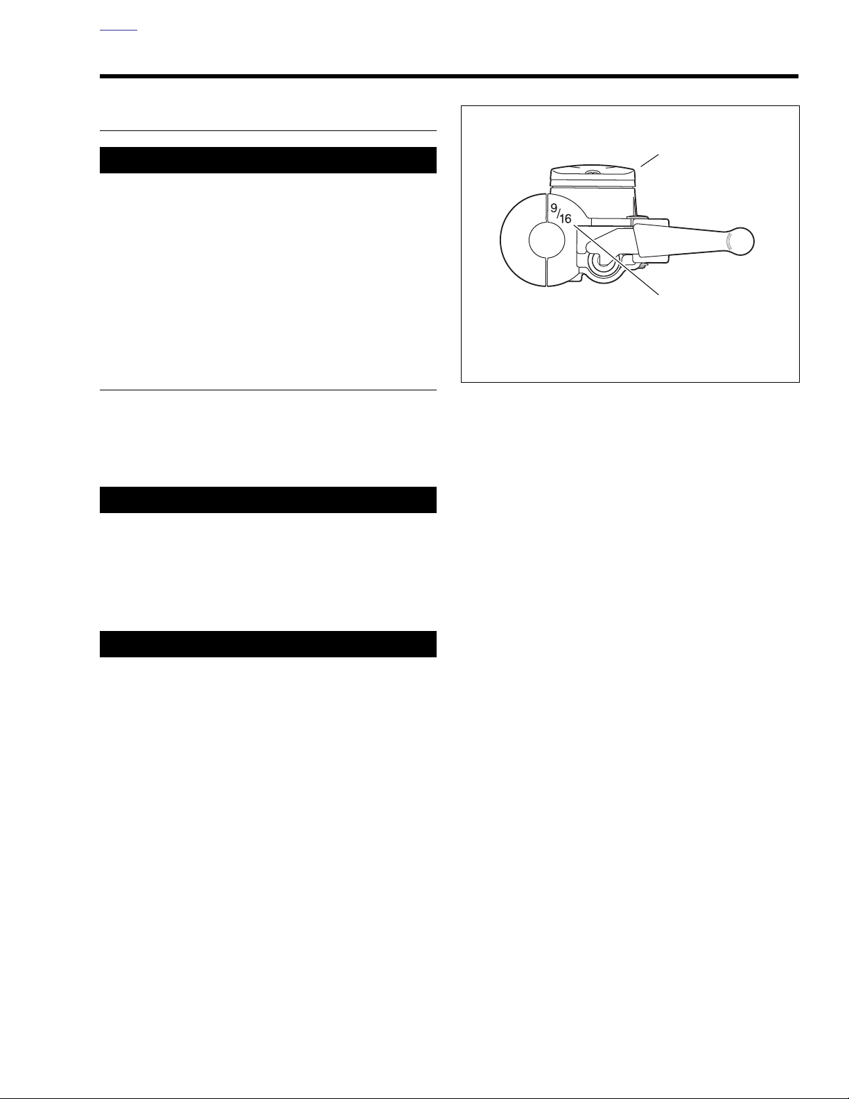
HOME
d0483a2x
1. Single disc master cylinder
2. Bore stamp size
1
2
FRONT BRAKE MASTER CYLINDER 2.14
GENERAL
11WARNING1WARNING
Do not use parts from single caliper repair kits (9/16 inch
bore) on dual caliper models. Likewise, do not use parts
from dual caliper repair kits (11/16 inch bore) on single
caliper models. Using incorrect parts can cause brake
failure, which could result in death or serious injury.
(00278a)
See Figure 2-67. Master cylinders designed for single disc
(one caliper) operation have a 9/16 inch (14.3 mm) bore. The
bore size is stamped on the master cylinder assembly
inboard of the handlebar clamp bracket.
REMOVAL/DISASSEMBLY
1. Open bleeder nipple cap on front brake caliper. Install
end of a length of clear plastic tubing over caliper bleeder
valve, while placing free end in a suitable container.
Open bleeder valve about 1/2-turn. Pump brake hand
lever to drain brake fluid. Close bleeder valve.
Figure 2-67. Bore Size
CAUTION
Damaged banjo bolt surfaces will leak when reassembled.
Prevent damage to seating surfaces by carefully removing
brake line components.
2. Remove bolt and two steel/rubber washers to disconnect
fitting of hydraulic brake line from master cylinder. Discard washers.
CAUTION
Do not remove or install the master cylinder assembly
without first positioning a 5/32-inch (4 mm) thick insert
between the brake lever and lever bracket. Removing or
installing the master cylinder assembly without the
insert in place may result in damage to the rubber boot
and plunger on the front stoplight switch. (00324a)
2006 Dyna: Chassis 2-39
Page 98
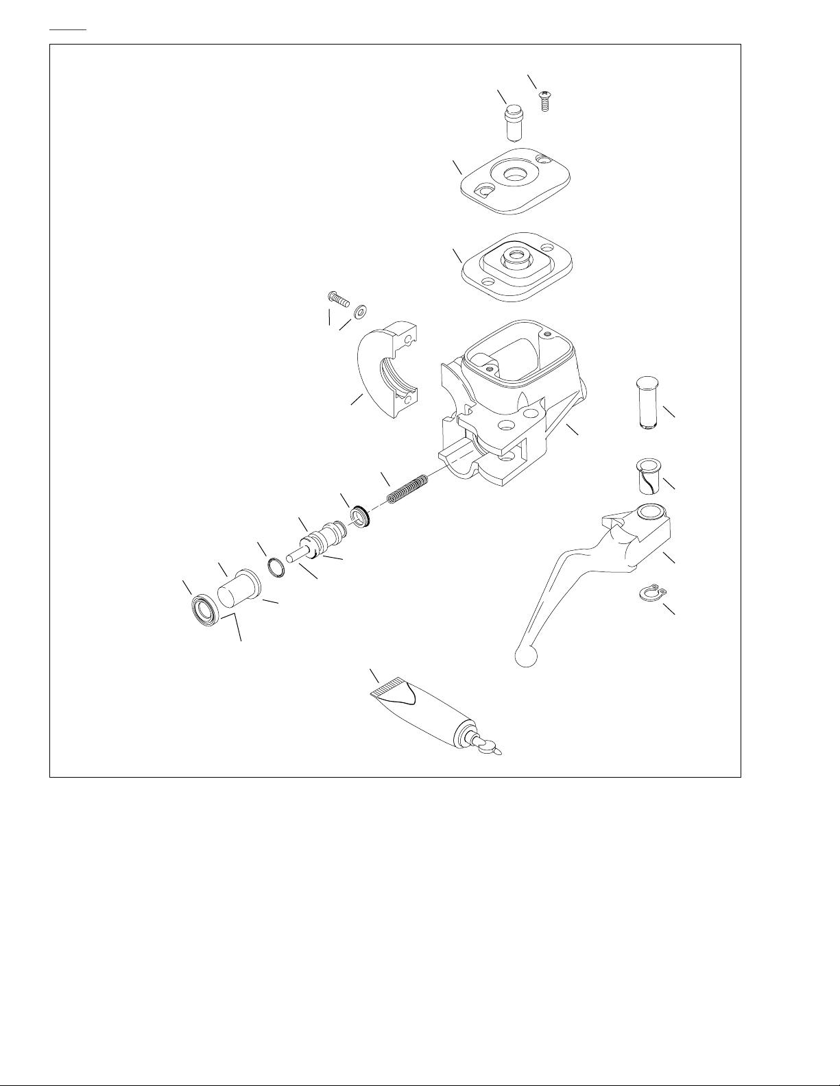
HOME
1. Lubricant
2. Wiper
3. Piston cap
4. O-ring
5. Piston
6. Primary cup
7. Spring
8. Handlebar clamp
9. T27 TORX screw and washer (2)
10. Gasket
11. Cover
12. Site glass
13. Screw (2)
14. Master cylinder reservoir
15. Pivot pin
16. Bushing
17. Brake hand lever
18. Retaining ring
13
12
11
10
9
8
15
14
7
6
16
5
4
3
2
Flat side
Service parts kit contains items 1-7.
● 9/16 in. bore - Part No. 45006-96C
O-ring groove
Pin
Shoulder
1
Figure 2-68. Front Brake Master Cylinder
17
18
d0484a2x
2-40 2006 Dyna: Chassis
Page 99
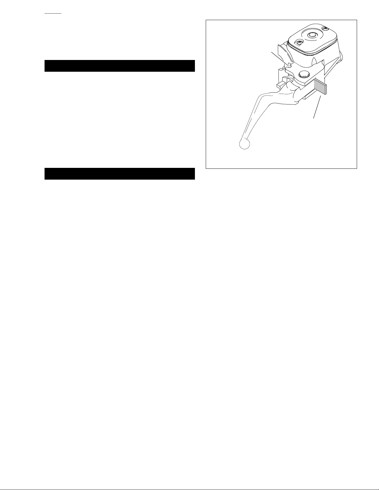
HOME
d0325x8x
1. Groove
2. 5/32 in. (4mm) thick cardboard insert
1
2
3. See Figure 2-69. Place the cardboard insert between the
brake lever and lever bracket.
4. See Figure 2-68. Remove the two T27 TORX screws with
flat washers (9) to detach the handlebar clamp (8) from
the master cylinder reservoir (14).
11WARNING1WARNING
Wear safety glasses or goggles when removing or installing retaining rings. Retaining rings can slip from the pliers and could be propelled with enough force to cause
serious eye injury. (00312a)
5. Remove retaining ring (18) from pivot pin groove at bottom of master cylinder bracket.
6. Remove pivot pin (15) and brake hand lever (17).
7. Carefully remove wiper (2) with pick or similar tool.
8. Remove piston cap (3).
9. Remove piston (5) with O-ring (4) and primary cup (6).
10. Remove spring (7).
CAUTION
Do NOT allow dirt or debris to enter the master cylinder
reservoir. Dirt or debris in the reservoir can cause
improper operation and equipment damage. (00205b)
11. Remove both screws (13), cover (11) and the cover gasket (10).
Figure 2-69. Cardboard Insert
2006 Dyna: Chassis 2-41
Page 100

HOME
CLEANING AND INSPECTION
11WARNING1WARNING
Do not use parts from single caliper repair kits (9/16 inch
bore) on dual caliper models. Likewise, do not use parts
from dual caliper repair kits (11/16 inch bore) on single
caliper models. Using incorrect parts can cause brake
failure, which could result in death or serious injury.
(00278a)
1. Always reassemble the master cylinder using new parts
from the correct repair kit (9/16 inch bore- HD Part No.
45006-96C.
11WARNING1WARNING
Use denatured alcohol to clean brake system components. Do not use mineral-based solvents (such as gasoline or paint thinner), which will deteriorate rubber parts
even after assembly. Deterioration of these components
can cause brake failure, which could result in death or
serious injury. (00291a)
2. Clean all parts with denatured alcohol or. Do not contaminate with mineral oil or other solvents. Wipe dry with a
clean, lint free cloth. Blow out drilled passages and bore
with a clean air supply. Do not use a wire or similar
instrument to clean drilled passages in bottom of reservoir.
3. Carefully inspect all parts for wear or damage and
replace as necessary.
4. Inspect the piston bore in the master cylinder housing for
scoring, pitting or corrosion. Replace the housing if any
of these conditions are found.
5. Inspect the outlet port that mates with the brake line fitting. As a critical sealing surface, replace the housing if
any scratches, dents or other damage is noted.
6. Inspect the cover gasket for cuts, tears or general deterioration. Replace as necessary.
ASSEMBLY/INSTALLATION
1. See Figure 2-68. Fit O-ring (4) into groove at front of piston (5) (pin side).
2. Fit primary cup (6) over lip at back of piston so that
closed side (smaller OD) contacts shoulder.
3. Coat piston bore of housing with special lubricant (1)
supplied in the service parts kit. Also apply the lubricant
to OD of installed O-ring (4) and primary cup (6).
4. Insert spring (7) into master cylinder bore so that it seats
against the recess at bottom.
5. Slide piston over spring.
6. Fit wiper (2) over piston cap (3) so that the flat side of
wiper contacts cap shoulder.
7. Fit piston cap over piston pin (5).
8. Press down on wiper until it contacts the counterbore.
Larger OD of wiper must be completely seated in groove
on outlet side of piston bore.
9. Install the cover (11) with gasket (10) on the master cylinder reservoir. Install two screws (13) to fasten the cover
to the reservoir, but do not tighten at this time.
10. Align hole in brake hand lever (17) with hole in master
cylinder bracket. From the top of the assembly, slide pivot
pin (15) through bracket and hand lever.
11WARNING1WARNING
Wear safety glasses or goggles when removing or installing retaining rings. Retaining rings can slip from the pliers and could be propelled with enough force to cause
serious eye injury. (00312a)
11. Install retaining ring (18) in pivot pin groove. Verify that
retaining ring is completely seated in groove.
CAUTION
Do not remove or install the master cylinder assembly
without first positioning a 5/32-inch (4 mm) thick insert
between the brake lever and lever bracket. Removing or
installing the master cylinder assembly without the
insert in place may result in damage to the rubber boot
and plunger on the front stoplight switch. (00324a)
2-42 2006 Dyna: Chassis
 Loading...