

Page 1
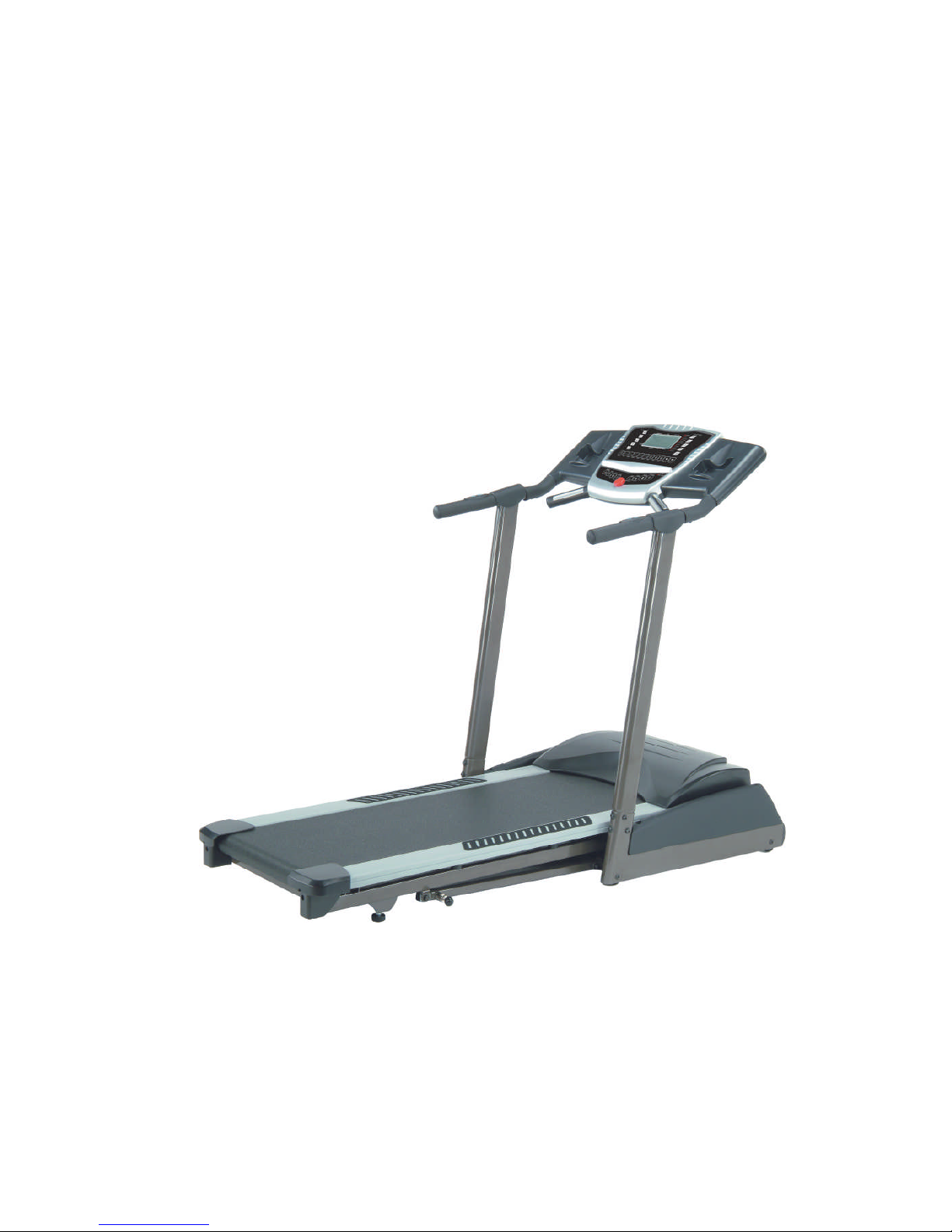
11662222773388TTrreeaaddmmiillllSSeerrvviicceeMMaannuuaal
l
Page 2

WARNING:
ALWAYS UNPLUG THE TREADMILL FROM THE ELECTRICAL
OUTLET BEFORE SERVICING THE UNIT.
Page 3

SSeerrvviicceeMMaannuuaall11662222773388TTrreeaaddmmiillllMMaauurriicceePPiinnccooffffssTTaabblleeooffCCoonntteennttss11((888888))770077--1188880
0
TTaabblleeooffCCoonntteennttss1
1
TABLE OF CONTENTS
Table of Contents...................................................................... 1
Table of Figures ........................................................................ 3
Description................................................................................ 4
A ELECTRICAL CONFIGURATION ....................................... 4
1. 1622738 Treadmill components ................................... 4
B GENERAL INFORMATION................................................. 5
1. Console ......................................................................... 5
2. Main controller.............................................................. 5
3. Treadmill motor ............................................................ 5
4. Incline motor................................................................. 5
Operation................................................................................... 9
A WINDOW DISPLAY MODE ............................................... 9
1. OFF Mode..................................................................... 9
2. READY Mode .............................................................. 9
3. SLEEP Mode ................................................................ 9
4. RUN Mode.................................................................... 9
B FUNCTION ...................................................................... 10
1. SPEED ........................................................................ 10
2. INCLINE..................................................................... 10
3. TIME........................................................................... 10
4. program/laps ............................................................... 11
5. DISTANCE................................................................. 11
6. CALORIES................................................................. 11
7. PULSE ........................................................................ 11
C FUNCTION BUTTON IN MAIN MODE............................. 13
1. READY MODE.......................................................... 13
2. RUN MODE ............................................................... 14
D CALIBRATION PROCEDURE........................................... 16
1. Calibration................................................................... 16
Page 4

SSeerrvviicceeMMaannuuaall11662222773388TTrreeaaddmmiillllMMaauurriicceePPiinnccooffffssTTaabblleeooffCCoonntteennttss11((888888))770077--1188880
0
TTaabblleeooffCCoonntteennttss2
2
Troubleshooting ...................................................................... 17
1. General........................................................................ 17
2. Troubleshooting Matrix .............................................. 18
Diagrams and Schematics....................................................... 27
APPENDIX A......................................................................... 32
1. TREADBELT ADJUSTMENT.................................. 32
APPENDIX B ......................................................................... 34
1. TREADMILL LUBRICATION ................................. 34
APPENDIX C ......................................................................... 35
1. RESET SWITCH RESETTING ................................. 35
APPENDIX D......................................................................... 36
1. FUSE REPLACEMENT............................................. 36
APPENDIX E ......................................................................... 37
1. SPEED SENSOR ADJUSTMENT............................. 37
2. SERVICE QUESTIONS............................................. 37
Page 5

SSeerrvviicceeMMaannuuaall11662222773388TTrreeaaddmmiillllMMaauurriicceePPiinnccooffffssTTaabblleeooffFFiigguurreess11((888888))770077--1188880
0
TTaabblleeooffFFiigguurreess3
3
TABLE OF FIGURES
Figure 1 Operational Flowchart ............................................... 8
Figure 2 Console Layout........................................................ 27
Figure 3 Mechanical Layout .................................................. 28
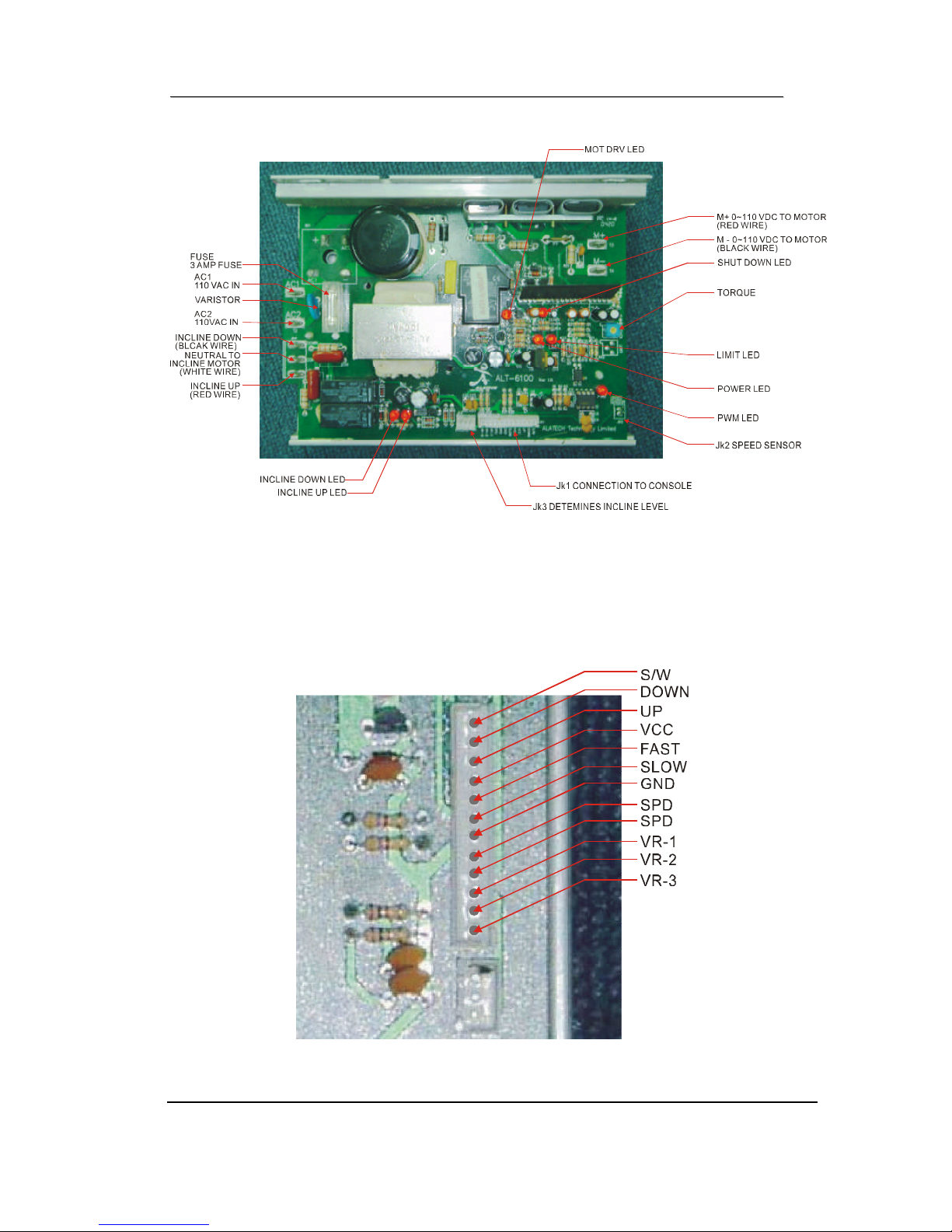
Figure 4 Main Controller information & voltages................. 29
Figure 5 Function JK1 connector on Main Controller........... 29
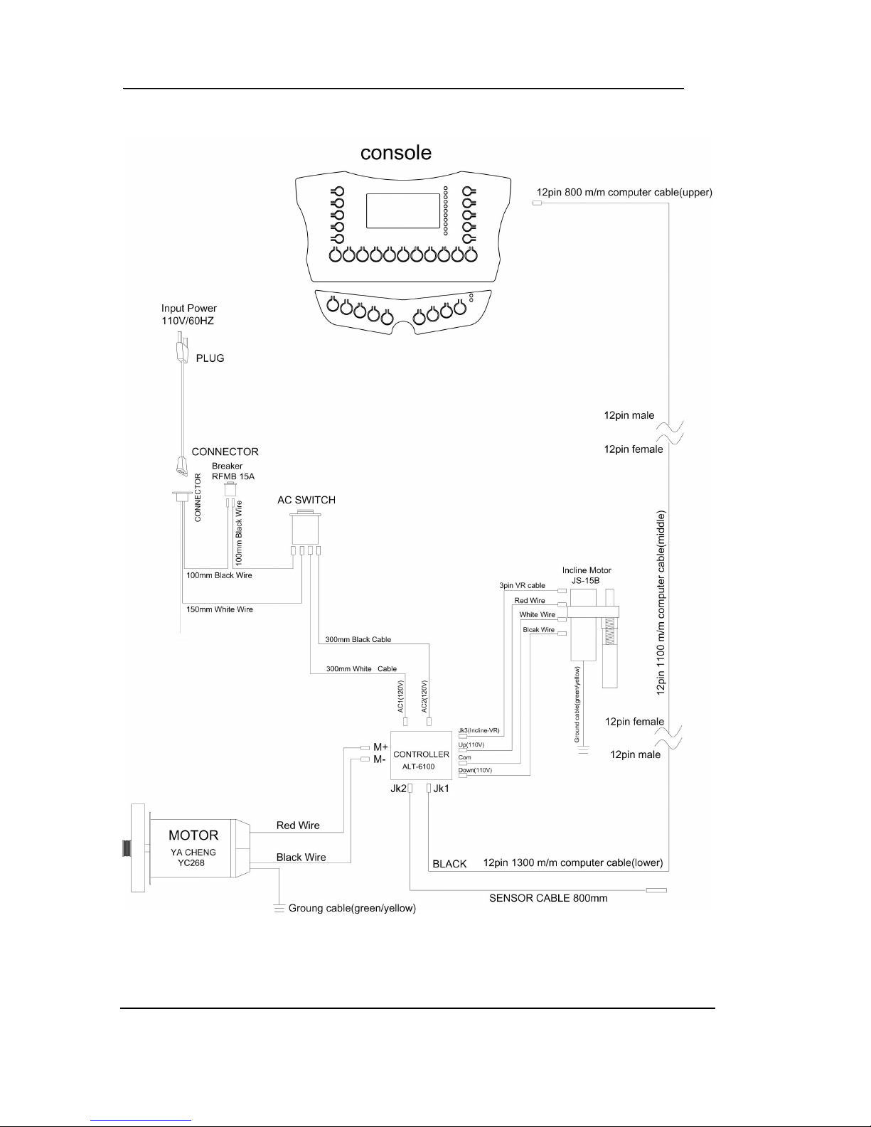
Figure 6 Wiring Diagram....................................................... 30
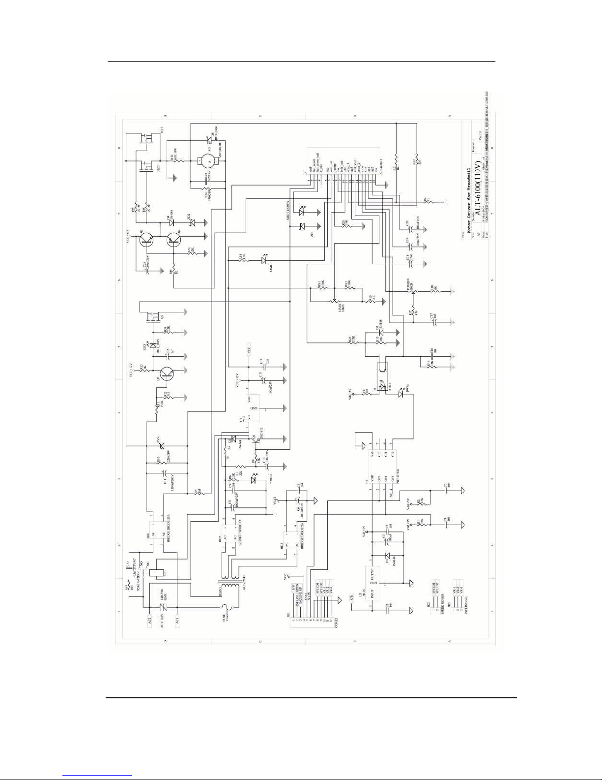
Figure 7 Schematic Diagram ................................................. 31
Figure 8 If Treadbelt slips...................................................... 32
Figure 9 If tread belt shifts too far to the Right ..................... 32
Figure 10 If tread belt shifts too far to the Left...................... 33
Figure 11 Resetting Reset switch........................................... 35
Figure 12 Fuse replacement................................................... 36
Page 6

SSeerrvviicceeMMaannuuaall11662222773388TTrreeaaddmmiillllMMaauurriicceePPiinnccooffffssDDeessccrriippttiioonn11((888888))770077--1188880
0
DDeessccrriippttiioonn4
4
DESCRIPTION
A ELECTRICAL CONFIGURATION
Note: Electrical servicing of this treadmill is limited to board
level replacement.
1. 1622738 TREADMILL COMPONENTS
a) Safety key:
Magnetic key that fits in the Console to activate all
functions.
b) Console:
Interface that controls all functions of the treadmill.
c) Main controller:
A circuit board that incorporates the DC power supply and
takes input from the console and sends out appropriate
voltages that control the treadmill functions.
d) Treadmill motor:
A variable speed, 0 - 220 volts D.C. motor that powers the
main running belt.
e) Incline motor:
An AC reversing motor that sets the incline of the treadmill.
Page 7

SSeerrvviicceeMMaannuuaall11662222773388TTrreeaaddmmiillllMMaauurriicceePPiinnccooffffssDDeessccrriippttiioonn11((888888))770077--1188880
0
DDeessccrriippttiioonn5
5
B GENERAL INFORMATION
1. CONSOLE
a) Contains touch controls and LCD windows Display.
2. MAIN CONTROLLER
a) Contains power supply and control circuits.
3. TREADMILL MOTOR
a) Variable speed 0-110 volts DC motor. Have three wires, red,
white and green.
b) If there is DC voltage on the Red wire (M+) the treadmill
motor will turn clockwise.
c) If there is DC voltage on the White wire (M-) the treadmill
motor will turn counter-clockwise.
d) The higher the voltage the faster the motor turns.
e) The Green wire is ground.
4. INCLINE MOTOR
a) Reversing 120 volts AC motor.
b) Have four wires, red, black, white and green.
c) Has one 3 pins cable of position sensor.
d) If there is AC voltage on the Red wire (DOWN) the incline
motor will increase the incline.
e) If there is AC voltage on the Black wire (UP) the incline
motor will decrease the incline.
Page 8

SSeerrvviicceeMMaannuuaall11662222773388TTrreeaaddmmiillllMMaauurriicceePPiinnccooffffssDDeessccrriippttiioonn11((888888))770077--1188880
0
DDeessccrriippttiioonn6
6
f) The White wire (COM) is neutral.
g) The Green wire is ground.
Page 9
SSeerrvviicceeMMaannuuaall11662222773388TTrreeaaddmmiillllMMaauurriicceePPiinnccooffffssDDeessccrriippttiioonn11((888888))770077--1188880
0
DDeessccrriippttiioonn7
7
Page 10

SSeerrvviicceeMMaannuuaall11662222773388TTrreeaaddmmiillllMMaauurriicceePPiinnccooffffssDDeessccrriippttiioonn11((888888))770077--1188880
0
DDeessccrriippttiioonn8
8
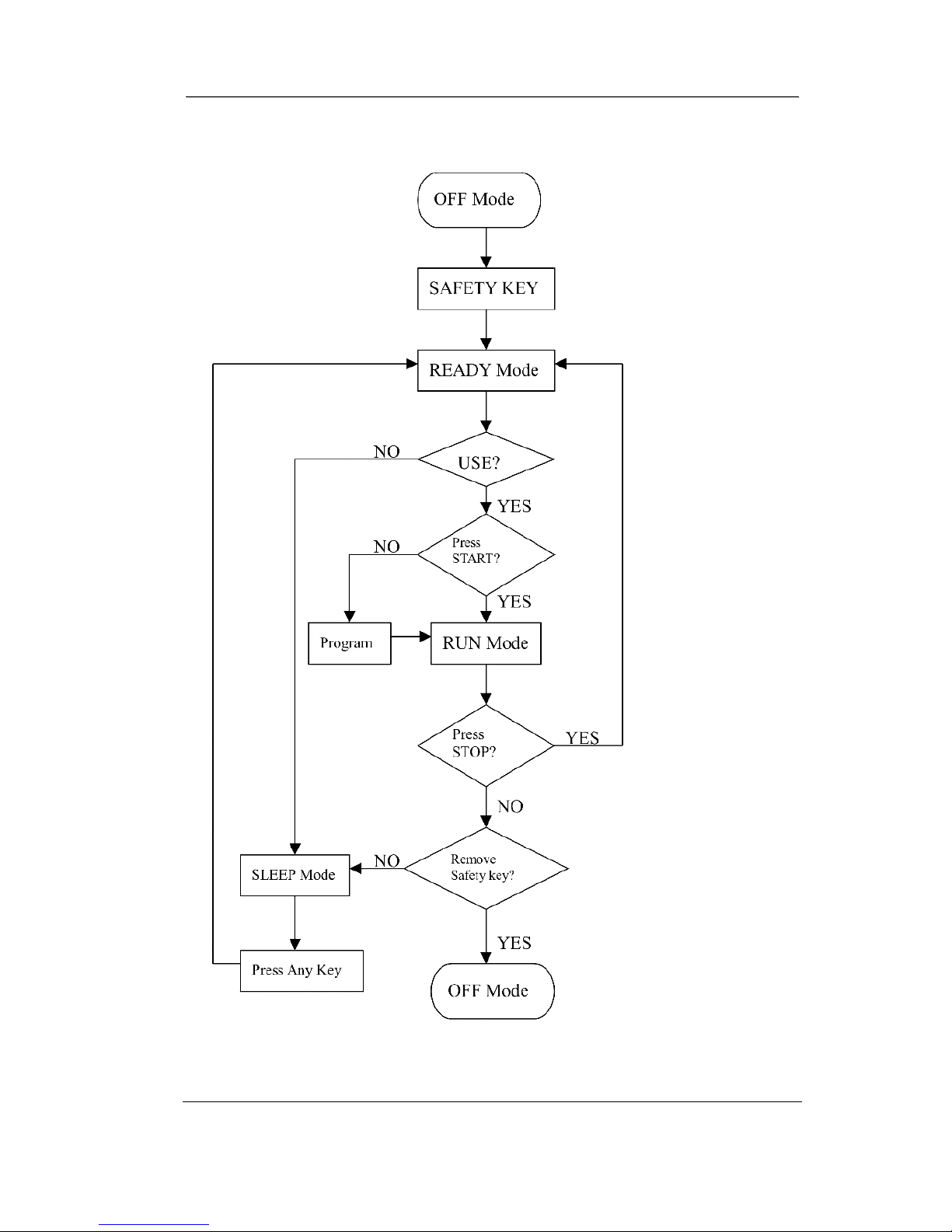
Figure 1 Operational Flowchart
Page 11

SSeerrvviicceeMMaannuuaall11662222773388TTrreeaaddmmiillllMMaauurriicceePPiinnccooffffssOOppeerraattiioonn11((888888))770077--1188880
0
OOppeerraattiioonn9
9
OPERATION
A WINDOW DISPLAY MODE
1. OFF MODE
a) When user doesn’t insert the SAFETY KEY on the console,
the treadmill enters the OFF Mode and all windows will
appear blank.
2. READY MODE
a) When the treadmill is ON and the SAFETY KEY is inserted
in console, the dot matrix will show “SELECT
PROGRAM”.
b) The LED will light in sequence from manual to H2.
c) Press START button to start treadmill on Manual mode.
3. SLEEP MODE
a) In SLEEP Mode, if “START” is pressed then the treadmill
enters READY Mode.
4. RUN MODE
a) In RUN Mode, pressing the “STOP” button and removing
the SAFETY KEY will cause the treadmill stop instantly
and enter OFF Mode.
Page 12

SSeerrvviicceeMMaannuuaall11662222773388TTrreeaaddmmiillllMMaauurriicceePPiinnccooffffssOOppeerraattiioonn11((888888))770077--1188880
0
OOppeerraattiioonn110
0
B FUNCTION
1. SPEED
a) Displays the current speed in Kilometer per hour.
b) DISPLAY range is 0.0 to 99.9 km.
c) WORK range is 1.0 to 16.0 km.
d) Press “FAST” or ”SLOW” to adjust speed, each increment
and decrement is 0.1 km.
2. INCLINE
a) Displays the incline position from 0 to 10.
b) DISPLAY range is 0 to 999.
c) WORK range is 0 to 10.
d) INCLINE preset value is 0 to 10.
e) Press “UP” or “ DOWN ” to adjust incline, each increment
and decrement is 1.
3. TIME
a) TIME is either COUNT UP or COUNT DOWN. System
preset is COUNT UP; if user sets the time then timer is
COUNT DOWN.
b) DISPLAY range is 0:00 to 99:59.
c) WORK range is 0:00 to 99:59.
d) COUNT DOWN setting range is 10:00 to 99:00.
e) When TIME is set, the count will go to zero.
Page 13

SSeerrvviicceeMMaannuuaall11662222773388TTrreeaaddmmiillllMMaauurriicceePPiinnccooffffssOOppeerraattiioonn11((888888))770077--1188880
0
OOppeerraattiioonn111
1
f) In RUN Mode, press “STOP” button to save value of time
and enter “RUN Mode” again that value will continue count
up time.
4. PROGRAM/LAPS
a) Display the total working lap quantity, LAPS and
PROGRAM state display in same window and pressing
“MODE” button will toggle between them.
b) DISPLAY range is 0 to 99.
c) WORK range is 0 to 99.
d) Displays total lap quantity.
5. DISTANCE
a) Displays the current distance in kilmeter.
b) DISPLAY range is 0.00 to 99.9.
c) WORK range is 0.00 to 99.9.
d) COUNT DOWN setup range is 0.10 to 99.90.
6. CALORIES
a) Displays the cumulative calories burned at any given time
during your workout.
b) DISPLAY range is 0.0 to 999.0.
c) WORK range is 0.0 to 999.0.
d) COUNT DOWN setup range is 1.0 to 999.0.
7. PULSE
Page 14

SSeerrvviicceeMMaannuuaall11662222773388TTrreeaaddmmiillllMMaauurriicceePPiinnccooffffssOOppeerraattiioonn11((888888))770077--1188880
0
OOppeerraattiioonn112
2
Displays the heart beat by using hand pulse or receiver. If use
receiver, then a chest belt must be worn.
a) DISPLAY range is 0 to 999.
b) WORK range is 60 to 220.
c) In RUN Mode, if the treadmill doesn’t have a signal for 8
seconds then display value will become “P”.
Page 15

SSeerrvviicceeMMaannuuaall11662222773388TTrreeaaddmmiillllMMaauurriicceePPiinnccooffffssOOppeerraattiioonn11((888888))770077--1188880
0
OOppeerraattiioonn113
3
C FUNCTION BUTTON IN MAIN MODE
1. READY MODE
a) SAFETY KEY: Put safety key in position to power on the
computer. When safety key is pulled away from its position,
the computer will be automatically shut down.
b) STOP button: Non-function.
c) START button: Press “START” button to start training.
When pressing “START” button, there will be 3 seconds
final count down by a buzzer, then machine starts running.
In MANUAL, treadmill starts at MIN SPEED and treadmill
starts at program preset value in PROGRAM.
d) MODE button: Press “MODE” button to change each
function. MANUAL can set using time, Pre-set PROGRAM
can set using time and speed, Heart Rate Control 1~2 can
set time, age and the value of heart rate. User Program 1~3
can set time, speed and incline. Press “MODE” button for 2
seconds to reset all screen data.
e) Manual button: Press “Manual” button to select manual.
f) Pre-set Program button 1~5 buttons: Press “Pre-set Program
1~5” buttons to select training in different program profiles.
g) User Program 1~3 buttons: Press “User Program 1~3”
buttons to select in different User program.
h) Heart Rate Control 1~2 buttons: Press “Heart Rate Control
1~3” button to select in different Heart Rate Program.
i) FAST button: If user doesn’t enter a setting then this button
is non-functional.
j) SLOW button: If user doesn’t enter a setting then this button
is non-functional.
Page 16

SSeerrvviicceeMMaannuuaall11662222773388TTrreeaaddmmiillllMMaauurriicceePPiinnccooffffssOOppeerraattiioonn11((888888))770077--1188880
0
OOppeerraattiioonn114
4
k) UP button: If user doesn’t enter a setting then this button is
non-functional.
l) DOWN button: If user doesn’t enter a setting then this
button is non-functional.
m) SPEED RAPID button: Non-function.
n) INCLINE RAPID button: Non-function.
2. RUN MODE
a) SAFETY KEY: When safety key is pulled away from its
position, the computer will be automatically shut down.
b) STOP button: press “STOP” button to stop treadmill.
c) START button: non-functional.
d) MODE button: Exchange display between LAPS and
operation mode.
e) Manual button: non-function.
f) Pre-set Program button 1~5 buttons: non-function.
g) User Program 1~3 buttons: non-function.
h) Heart Rate Control 1~2 buttons: non-function.
i) FAST button: Press the button to increase your speed and
each increase is 0.1 kph. If button is pressed continuously
then speed increases to MAX SPEED quickly.
j) SLOW button: Press the button to decrease your speed and
each decrease is 0.1kph. If button is pressed continuously
then speed decreases to MIN SPEED quickly.
k) UP button: Press the button to raise position and each
increase is 1, the minimum incline position is 10.
Page 17

SSeerrvviicceeMMaannuuaall11662222773388TTrreeaaddmmiillllMMaauurriicceePPiinnccooffffssOOppeerraattiioonn11((888888))770077--1188880
0
OOppeerraattiioonn115
5
l) DOWN button: Press the button to raise position and each
increase is 1, the minimum incline position is 0.
m) SPEED RAPID button: Speed will set to 3 kph, 5 kph, 7 kph,
9 kph, and 11 kph quickly.
n) INCLINE RAPID button: Incline will set to 2, 4, 6, 8, 10
position quickly.
Page 18

SSeerrvviicceeMMaannuuaall11662222773388TTrreeaaddmmiillllMMaauurriicceePPiinnccooffffssOOppeerraattiioonn11((888888))770077--1188880
0
OOppeerraattiioonn116
6
D CALIBRATION PROCEDURE
1. CALIBRATION
a) Turn on power.
b) Press and hold “START” and “MODE” button at the same
time.
c) Inserts the SAFETY KEY on console, all windows will
appear blank.
d) Km/Mile Mode: Press “STOP” button to exchange to
Kilometer Mode in SPEED window and the value is km.
e) Set wheel size: Press “FAST” or “SLOW” button to adjust
SPEED window to 2.3.
f) Press “START” button to memorize above setting and enter
next section of setting mode.
g) Set Min. speed: Press “FAST” or “SLOW” button to adjust
SPEED window to 1.0.
h) Press “START” button to memorize above setting and enter
next section of setting mode.
i) Set high speed: Press “FAST” or “SLOW” button to adjust
SPEED window to 16.0.
j) Set high incline position: Press “UP” or “DOWN” button to
adjust INCLINE window to 10.
k) Press “START” button to memorize all value, the treadmill
will calibrate automatically.
l) After calibrating, treadmill will reset then enter “READY
MODE”.
Page 19

SSeerrvviicceeMMaannuuaall11662222773388TTrreeaaddmmiillllMMaauurriicceePPiinnccooffffssTTrroouubblleesshhoooottiinngg11((888888))770077--1188880
0
TTrroouubblleesshhoooottiinngg117
7
TROUBLESHOOTING
WARNING:
ALWAYS UNPLUG THE TREADMILL FROM THE ELECTRICAL
OUTLET BEFORE SERVICING THE UNIT.
1. GENERAL
a) Do a visual check of all wiring and connections looking for
chafed wires or lose connections.
b) Make sure any wiring is safely positioned and/or secured
away from moving parts.
c) If you find a fuse blown on a circuit board replace the
circuit board.
Page 20

SSeerrvviicceeMMaannuuaall11662222773388TTrreeaaddmmiillllMMaauurriicceePPiinnccooffffs
s
TTrroouubblleesshhoooottiinng
g
11((888888))770077--1188880
0
TTrroouubblleesshhoooottiinngg118
8
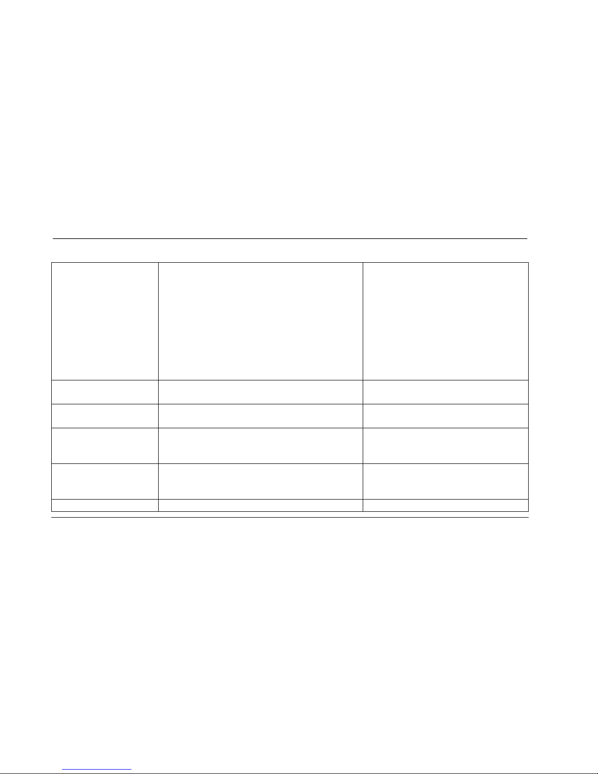
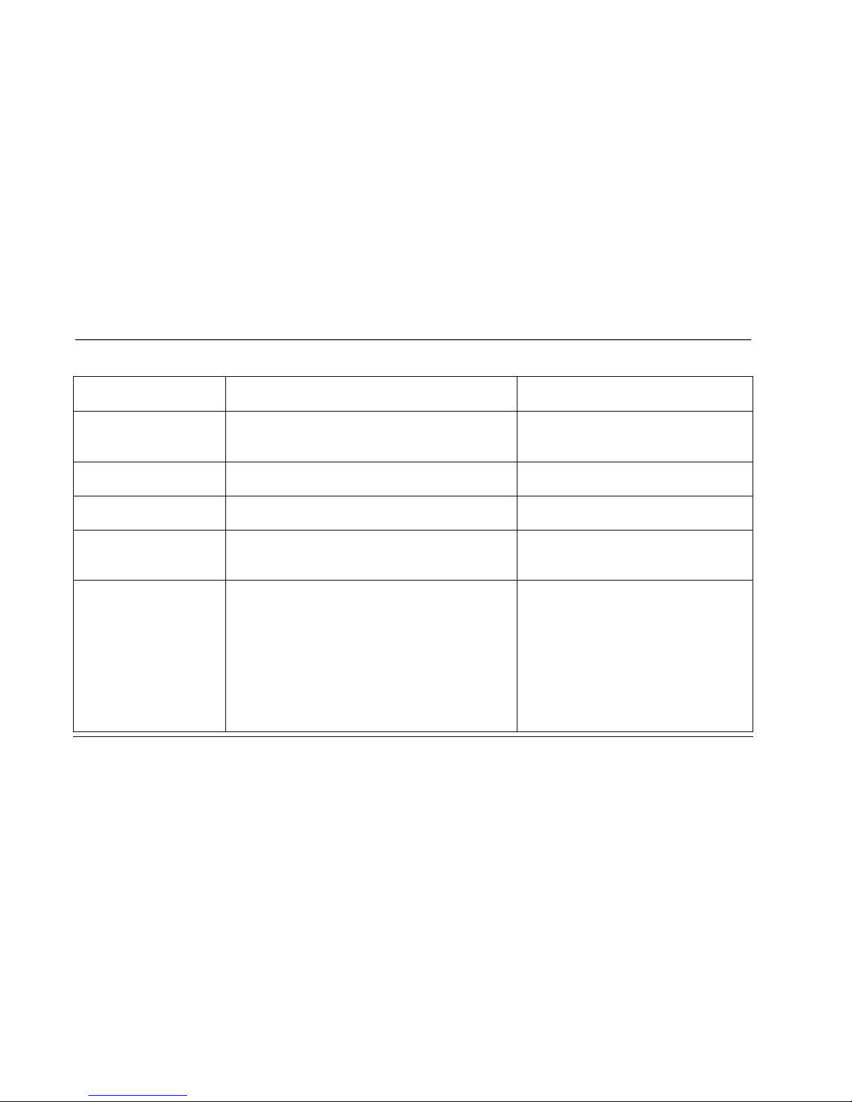
2. TROUBLESHOOTING MATRIX
Condition
Reason
Solve
When turn on power,
ON/OFF switch isn’t lit.
1 Power cord isn’t plugged into outlet.
2 Power cord isn’t plug into unit.
3 The voltage of outlet is too low.
4 Plug or connector of power cord is open.
5 Connector of power cord is broken.
6 Connecting cable disconnected.
7 Breaker tripped.
8 Breaker is broken.
9 ON/OFF switch is broken.
1 Plug the power cord into outlet.
2 Plug the power cord into unit.
3 Check the voltage of outlet.
4 Replace power cord.
5 Replace power cord.
6 Check if wire is disconnected, connect
it again.
7 Press the small red button to return to
original status.
8 Replace breaker.
9 Replace A.C switch.
After turning on power,
treadmill has a popping
sound.
1 Incorrect input power, varistor is blown broken
on controller.
1 Check the voltage of power is 120V.
Replace controller.
When insert safe key, no
display on monitor.
1 Haven’t switch ON/OFF switch.
2 Insert the Safe key on wrong position.
3 12PIN Computer connector not plugged in
1 Switch the A.C switch.
2 Insert the safe key on right position.
3 Please check the wire and connect
Page 21

SSeerrvviicceeMMaannuuaall11662222773388TTrreeaaddmmiillllMMaauurriicceePPiinnccooffffssTTrroouubblleesshhoooottiinngg11((888888))770077--1188880
0
TTrroouubblleesshhoooottiinngg119
9
properly.
4 12PIN computer cable is broken.
5 Fuse on controller is blown.
6 Varistor on controller is blown.
7 Reed switch of console is broken. (open)
8 Other components are faulty.
again.
4 Replace 12PIN computer cable.
5 Replace fuse or controller.
6 Replace varistor or controller.
7 Replace reed switch or console.
8 Replace console.
With no safe key but
treadmill could display or
operate.
1 Reed switch of console is broken. (short)
2 Have other magnetic components on console.
1 Replace reed switch or console.
2 Remove magnetic component beside
safe key.
When press “START”,
treadmill doesn’t start.
1 Motor M+ or M- wire isn’t connected into right
position.
2 Controller is broken. (No power to motor)
3 Motor is broken.
4 Treadmill controller shut down and LED would
be ON
1 Please check and plug again.
2 Replace controller.
3 Replace motor.
4 Turn off the AC switch and turn on
power again.
Treadmill stops or shuts
off by itself.
1 House breaker tripped.
2 Treadmill breaker tripped.
3 Treadmill controller fuse is broken.
4 Treadmill controller shut down and LED would
1 Reset it.
2 Reset treadmill breaker.
3 Replace fuse
4 Turn off the AC switch and turn on
Page 22

SSeerrvviicceeMMaannuuaall11662222773388TTrreeaaddmmiillllMMaauurriicceePPiinnccooffffssTTrroouubblleesshhoooottiinngg11((888888))770077--1188880
0
TTrroouubblleesshhoooottiinngg220
0
be ON.
power again.
After removing safe key,
treadmill can’t stop.
5 Reed switch of console is broken.
5 Replace reed switch or console.
LEDs not bright,
incomplete or imperfect.
1 LED light is broken or power to console too low.
1 Replace LED or console.
2 Check AC power is 120V
3 Check power to console.
4 Replace lower controller.
LCD display not bright,
incomplete or imperfect.
1 LCD display is broken.
1 Replace console and calibrate it.
When press “START”
button to start treadmill,
running belt isn’t running
and window displays
“LS” error message after
8 seconds.
1. Controller experienced unusual shut down, the
S_D light will be always bright.
2. Motor wires (red, black) aren’t plugged into
controller.
3. Computer cables not connected properly.
4. Computer cables are broken or damaged.
5. Motor belt is broken.
6. Controller is broken.
7. Motor is broken.
8. Console is broken.
1 Turn off power and reset the treadmill.
2 Plug wires again.
3 Plug the wire again on controller,
connector and console.
5 Replace the wires.
6 Replace motor belt.
7 Replace controller.
8 Replace motor.
9 Replace console.
When press “START”
1. Misalignment between speed sensor and magnet.
1 Adjust the distance to 5mm between
Page 23
SSeerrvviicceeMMaannuuaall11662222773388TTrreeaaddmmiillllMMaauurriicceePPiinnccooffffssTTrroouubblleesshhoooottiinngg11((888888))770077--1188880
0
TTrroouubblleesshhoooottiinngg221
1
button to start treadmill,
running belt is running but
window displays “LS”
error message after 8
seconds.
*Speed sensor cable was
broken, (open) console
can’t receive the speed.
2. Magnet missing.
3. Magnet de-magnetized.
4. Speed sensor cable is broken. (short)
5. 12 PIN computer cable connected improperly.
6. 12 PIN computer cable is broken.
7. Console is broken.
speed sensor and magnet.
2 Replace a magnet.
3 Use metal material to test the magnet.
4 Replace sensor cable.
5 Plug the cable again on controller,
connector and console.
6 Gray and purple wires got damage,
replace the wires.
7 Replace console.
SPEED windows display
is not 1.0 to 16.0 km
1 Console is not calibrated.
1 Calibrate the console.
INCLINE windows
display is not 0 to 10
1 Console is not calibrated.
1 Calibrate the console.
The speed of the belt
doesn’t match console
display.
1 Console is not calibrated.
1 Calibrate the console.
The incline position
doesn’t match console
display.
1 Console is not calibrated.
1 Calibrate the console.
INCLINE window
1 Position sensor value of incline motor is wrong.
1 Turn off the AC switch and turn on
Page 24
SSeerrvviicceeMMaannuuaall11662222773388TTrreeaaddmmiillllMMaauurriicceePPiinnccooffffssTTrroouubblleesshhoooottiinngg11((888888))770077--1188880
0
TTrroouubblleesshhoooottiinngg222
2
displays “E2”.
power again.
2 Calibrate the monitor.
INCLINE window
displays “E2” during
training.
1 Position sensor value of incline motor is wrong.
1 Turn off power and reset the treadmill.
INCLINE window
displays “----”.
1 Position sensor value of incline motor is wrong.
1 Check the 3 pins cable of the incline
motor isn’t on controller jk3
TIME window displays
“Err”
1 EEPROM is broken.
1 Replace console and calibrate it.
After pressing “START”
button, the treadmill stops
immediately.
1 Controller is broken.
1 Turn off the AC switch and turn on
power again.
2 Replace controller and calibrate it.
FAST/SLOW button of
SPEED ADJUSTMENT
SWITCH can’t be used.
1 The connector of SPEED CABLE (UPPER) and
CONSOLE not connected properly.
2 The connector of SPEED CABLE (UPPER) and
SPEED ADJUSTMENT SWITCH W/CABLE
not connected properly.
3 The connector of SPEED CABLE (UPPER) or
SPEED ADJUSTMENT SWITCH/W/CABLE is
damaged.
4 Button of SPEED ADJUSTMENT SWITCH is
1 Connect the wires again.
2 Connect the wires again.
3 Replace cable.
4 Replace buttons.
Page 25

SSeerrvviicceeMMaannuuaall11662222773388TTrreeaaddmmiillllMMaauurriicceePPiinnccooffffssTTrroouubblleesshhoooottiinngg11((888888))770077--1188880
0
TTrroouubblleesshhoooottiinngg223
3
Speed button just can
press FAST, can’t press
SLOW.
Speed button just can
press SLOW, can’t press
FAST.
broken.
5 The connector of SPEED CABLE (UPPER) or is
SPEED ADJUSTMENT SWITCH/W/CABLE
damage.
6 The connector of SPEED CABLE (UPPER) or
SPEED ADJUSTMENT SWITCH/W/CABLE
got damage.
5 Replace cable.
6 Replace cable.
UP/DOWN button of
INCLINE
ADJUSTMENT SWITCH
can’t be used.
Incline button just can
1 The connector of INCLINE CABLE (UPPER)
and CONSOLE not connected properly.
2 The connector of INCLINE CABLE (UPPER)
and INCLINE ADJUSTMENT SWITCH
W/CABLE not connected properly.
3 The connector of INCLINE CABLE (UPPER) or
INCLINE ADJUSTMENT SWITCH CABLE
got damage.
4 Button of INCLINE ADJUSTMENT SWITCH is
broken.
5 The connector of INCLINE CABLE (UPPER) or
1 Connect the wires again.
2 Connect the wires again.
3 Replace the cable.
4 Replace buttons.
5 Replace the cable.
Page 26

SSeerrvviicceeMMaannuuaall11662222773388TTrreeaaddmmiillllMMaauurriicceePPiinnccooffffssTTrroouubblleesshhoooottiinngg11((888888))770077--1188880
0
TTrroouubblleesshhoooottiinngg224
4
press UP, can’t press
DOWN.
Incline button just can
press DOWN, can’t press
UP.
INCLINE ADJUSTMENT SWITCH CABLE
got damage.
6 The connector of INCLINE CABLE (UPPER) or
INCLINE ADJUSTMENT SWITCH CABLE
damaged.
6 Replace the cable.
Hand pulse lost its
function.
(No pulse displayed on
monitor)
1 Hands not on the hand pulse sensor or only one
hand on sensor.
2 The connector of HANDPULSE W/WIRE and
Console not connected properly.
3 The wires got damaged when connecting the
HANDPULSE W/WIRE and Console.
4 Hand pulse board is broken.
1 Two hands hold the hand pulse.
2 Connect the wires again.
3 Replace wires.
4 Replace console or hand pulse board.
Wireless lost its function.
(No pulse displayed on
monitor)
1 Chest belt not worn properly.
2 Distance is too far and exceeds range of receiver.
3 Chest belt battery is weak or dead.
1 Check chest belt has proper contact
with skin and is oriented correctly.
2 User chest belt in front of console
within 3 feet.
3 Replace the lithium battery with type
CR2032.
Chest belt too close to the
treadmill.
1 Weak battery.
1 Replace the lithium battery with type
CR2032.
Page 27
SSeerrvviicceeMMaannuuaall11662222773388TTrreeaaddmmiillllMMaauurriicceePPiinnccooffffssTTrroouubblleesshhoooottiinngg11((888888))770077--1188880
0
TTrroouubblleesshhoooottiinngg225
5
Tread belt does not run in
center.
1 Tread belt tension not even across tread belt.
1 See treadbelt adjustment
(see Appendix A)
Tread belt hesitates while
being stepped on.
1 Insufficient lubricant on tread belt.
Tread belt tension insufficient.
1See treadbelt lubrication (see Appendix B)
Tension belt
Black particles collecting
under treadmill.
1 Drive belt is breaking in.
1 Vacuum under treadmill periodically.
Noise under motor cover.
1 Worn brushes or bearings on motor.
2 Front roller bearings are defective.
3 Drive belt is misadjusted (too tight or too loose).
1 Replace motor.
2 Replace front roller.
3 Adjust motor position.
Noise in the rear of the
treadmill.
1 Rear roller bearings are defective.
2 Rear roller misaligned.
1 Replace rear roller.
2 Adjust rear roller position.
Page 28
SSeerrvviicceeMMaannuuaall11662222773388TTrreeaaddmmiillllMMaauurriicceePPiinnccooffffssTTrroouubblleesshhoooottiinngg11((888888))770077--1188880
0
TTrroouubblleesshhoooottiinngg226
6
ndicator signal
Function
Condition: LED ON
Reason
Solve
PWM
Motor speed
When motor running, the light would
be getting light or dark in accordance
with speed.
Don’t have input.
Replace controller.
POWER
Controller power
The DC voltage is normal it would be
always bright.
Voltage is not correctly.
Fuse was broken.
Transformer was broken.
To check the voltage is 220-230V.
Replace Fuse.
Replace controller.
LIMIT
Limit the current of
DC motor.
When current of motor exceed 21A,
the LED will be bright.
If LIMIT light is bright for 3 to 5
seconds, the S_D light will be bright
at the same time.
Loading is too weight.
Operation is not correct,
motor lock.
Loading doesn’t exceed 150kgs.
S_D
Controller has
unusual with shut
down.
Controller has unusual with shut
down, the S_D light will be always
bright.
Motor lock, LIMIT light
will be bright for 3 to 5
seconds.
Turn off power and reset the treadmill.
MOT_DRV
Motor has unusual of
Drive Circuit.
Motor has unusual of Drive Circuit or
protect controller that light will be
bright.
Fuse was broken.
Drive IC was broken.
Replace controller.
Replace “Drive IC”.
UP
Motion of incline
motor
Motion of incline motor is up.
Fuse was broken.
Replace the controller.
DOWN
Motion of incline
motor
Motion of incline motor is down.
Fuse was broken.
Replace the controller.
Page 29
SSeerrvviicceeMMaannuuaall11662222773388TTrreeaaddmmiillllMMaauurriicceePPiinnccooffffssDDiiaaggrraammssaannddSScchheemmaattiiccss11((888888))770077--1188880
0
DDiiaaggrraammssaannddSScchheemmaattiiccss227
7
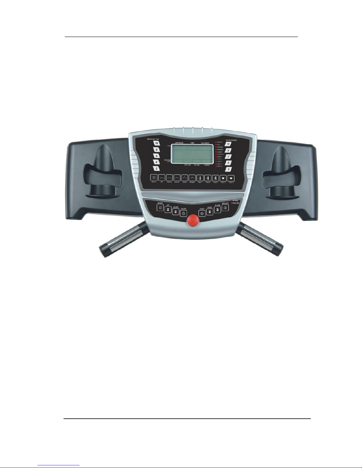
DIAGRAMS AND SCHEMATICS
Figure 2 Console Layout
Page 30
SSeerrvviicceeMMaannuuaall11662222773388TTrreeaaddmmiillllMMaauurriicceePPiinnccooffffssDDiiaaggrraammssaannddSScchheemmaattiiccss11((888888))770077--1188880
0
DDiiaaggrraammssaannddSScchheemmaattiiccss228
8
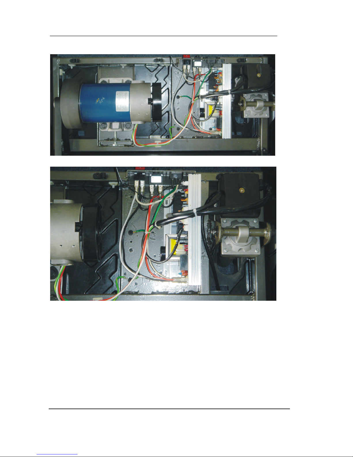
Figure 3 Mechanical Layout
Page 31
SSeerrvviicceeMMaannuuaall11662222773388TTrreeaaddmmiillllMMaauurriicceePPiinnccooffffssDDiiaaggrraammssaannddSScchheemmaattiiccss11((888888))770077--1188880
0
DDiiaaggrraammssaannddSScchheemmaattiiccss229
9
Figure 4 Main Controller information & voltages
Figure 5 Function JK1 connector on Main Controller
Page 32
SSeerrvviicceeMMaannuuaall11662222773388TTrreeaaddmmiillllMMaauurriicceePPiinnccooffffssDDiiaaggrraammssaannddSScchheemmaattiiccss11((888888))770077--1188880
0
DDiiaaggrraammssaannddSScchheemmaattiiccss330
0
Figure 6 Wiring Diagram
Page 33
SSeerrvviicceeMMaannuuaall11662222773388TTrreeaaddmmiillllMMaauurriicceePPiinnccooffffssDDiiaaggrraammssaannddSScchheemmaattiiccss11((888888))770077--1188880
0
DDiiaaggrraammssaannddSScchheemmaattiiccss331
1
Figure 7 Schematic Diagram
Page 34
SSeerrvviicceeMMaannuuaall11662222773388TTrreeaaddmmiillllMMaauurriicceePPiinnccooffffs
s
AAPPPPEENNDDIIXXAA11((888888))770077--1188880
0
AAPPPPEENNDDIIXXAA332
2
APPENDIX A
1. TREADBELT ADJUSTMENT
The treadbelt has been factory pre-adjusted, however if during the
operation:
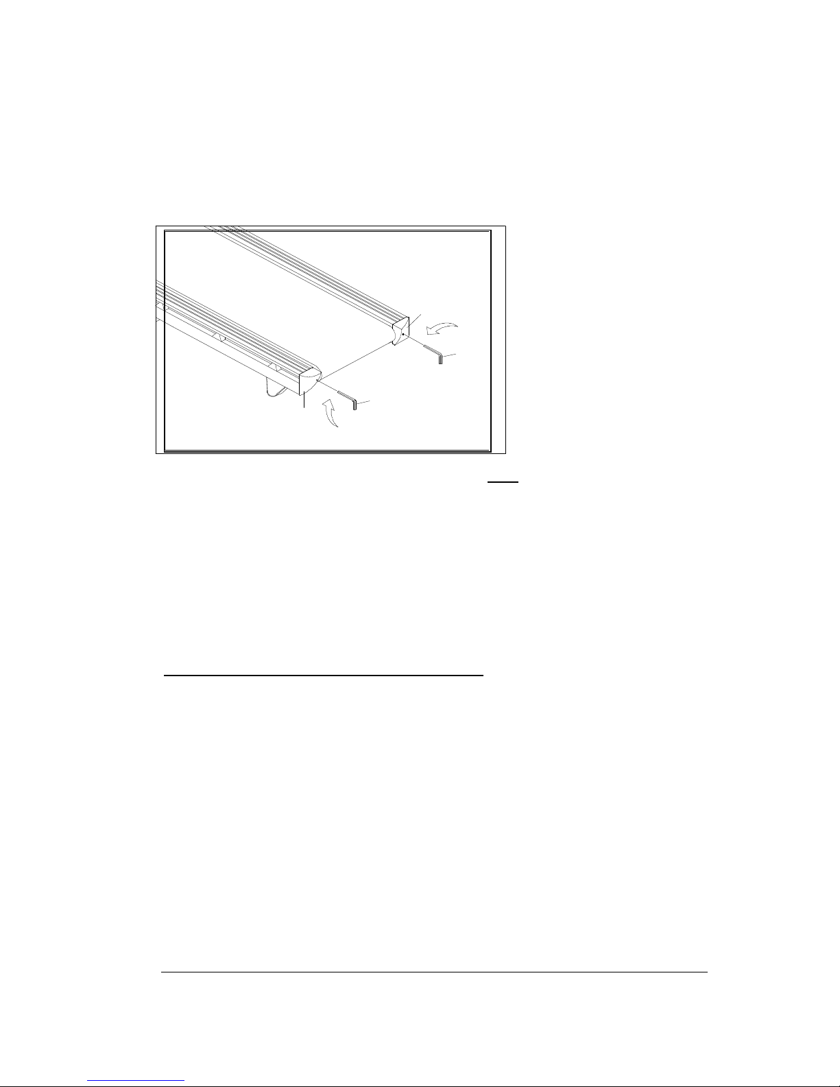
1/4 TURN
Figure 8 If Treadbelt slips
The treadbelt is too loose:
Tighten both rear roller adjusting bolts
1/4 turn clockwise using allen wrench
1/4 TURN
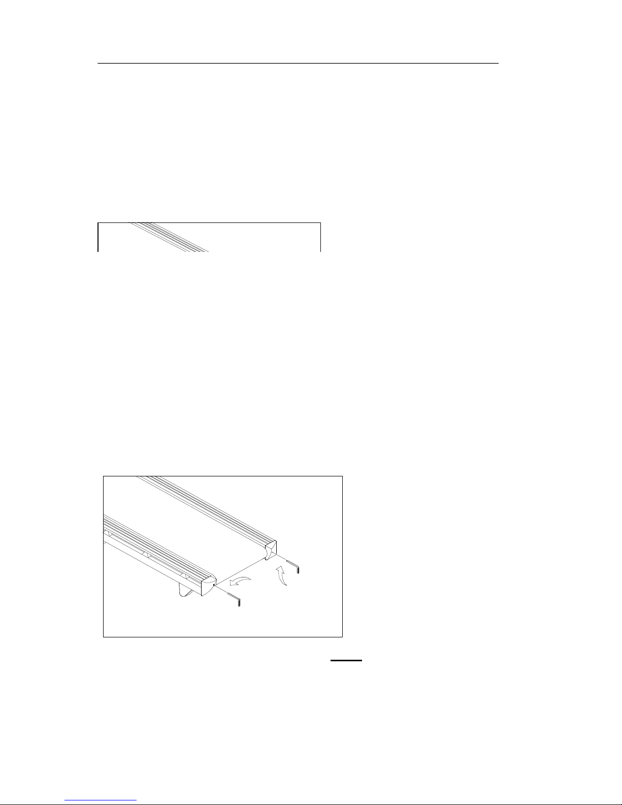
Figure 9 If tread belt shifts too far to the Right
a) Set the treadmill speed to 3.5 mph/5.6 km.
b) Tighten the right adjusting bolt a 1/4 turn clockwise using allen wrench
Page 35
SSeerrvviicceeMMaannuuaallSSeeaarrss330066886600TTrreeaaddmmiillllMMaauurriicceePPiinnccooffffssAAPPPPEENNDDIIXXAA11((888888))770077--1188880
0
AAPPPPEENNDDIIXXAA333
3
c) Wait 15 seconds: if no change; turn the left adjusting bolt a 1/4 turn
counter-clockwise using allen wrench e) Repeat steps b and c until belt is
centered
307931
79
1/4 TURN
Figure 10 If tread belt shifts too far to the Left
a) Set the treadmill speed to 3.5 mph/5.6 km.
b) Tighten the left adjusting bolt a 1/4 turn clockwise using allen wrench
c) Wait 15 seconds: if no change; turn the right adjusting bolt a 1/4 turn
counter-clockwise using allen wrench
e) Repeat steps b and c until belt is centered
IMPORTANT
DO NOT OVERTIGHTEN TREADBELT
If treadbelt is overtightened, edges of treadbelt will begin to curl
CAUTION!! DO NOT ALLOW ANYONE TO WALK ON
TREADBELT WHILE YOU ARE ADJUSTING.
Page 36

SSeerrvviicceeMMaannuuaall11662222773388TTrreeaaddmmiillllMMaauurriicceePPiinnccooffffssAAPPPPEENNDDIIXXBB11((888888))770077--1188880
0
AAPPPPEENNDDIIXXBB334
4
APPENDIX B
1. TREADMILL LUBRICATION
Your treadmill should require little maintenance other then periodically
applying lubricant. Lubricating under the treadbelt will ensure superior
performance and extend its life expectancy.
HOW TO CHECK TREADBELT FOR PROPER LUBRICATION
Lift one side of the treadbelt and feel the top surface of the treadboard
If the surface is (slick) to the touch, then no further lubrication is required
If the surface is dry to the touch, apply one packet of lubricant
HOW TO APPLY LUBRICANT
1. Lift one side of treadbelt.
2. Pour one half of the lubricant bottle under the center of the treadbelt on
the top surface of the treadboard
3. Walk on the treadmill at a slow speed for 3 to 5 minutes to evenly
distribute lubricant.
NOTE: DO NOT over lubricate treadboard. Any excess lubricant that
comes out should be wiped off.
IMPORTANT: ONLY USE HALF THE BOTTLE OF LUBRICANT
PER APPLICATION
LUBRICATION SCHEDULE
1. After the first 25 hours of use (2-3 months) apply one half bottle of
lubricant
2. Every 50 hours of use (5-8 months) apply one half bottle of lubricant
We recommend that you use:
Lube-N-Walk™ Treadmill Lubrication Kit.
Page 37
SSeerrvviicceeMMaannuuaall11662222773388TTrreeaaddmmiillllMMaauurriicceePPiinnccooffffssAAPPPPEENNDDIIXXCC11((888888))770077--1188880
0
AAPPPPEENNDDIIXXCC335
5
APPENDIX C
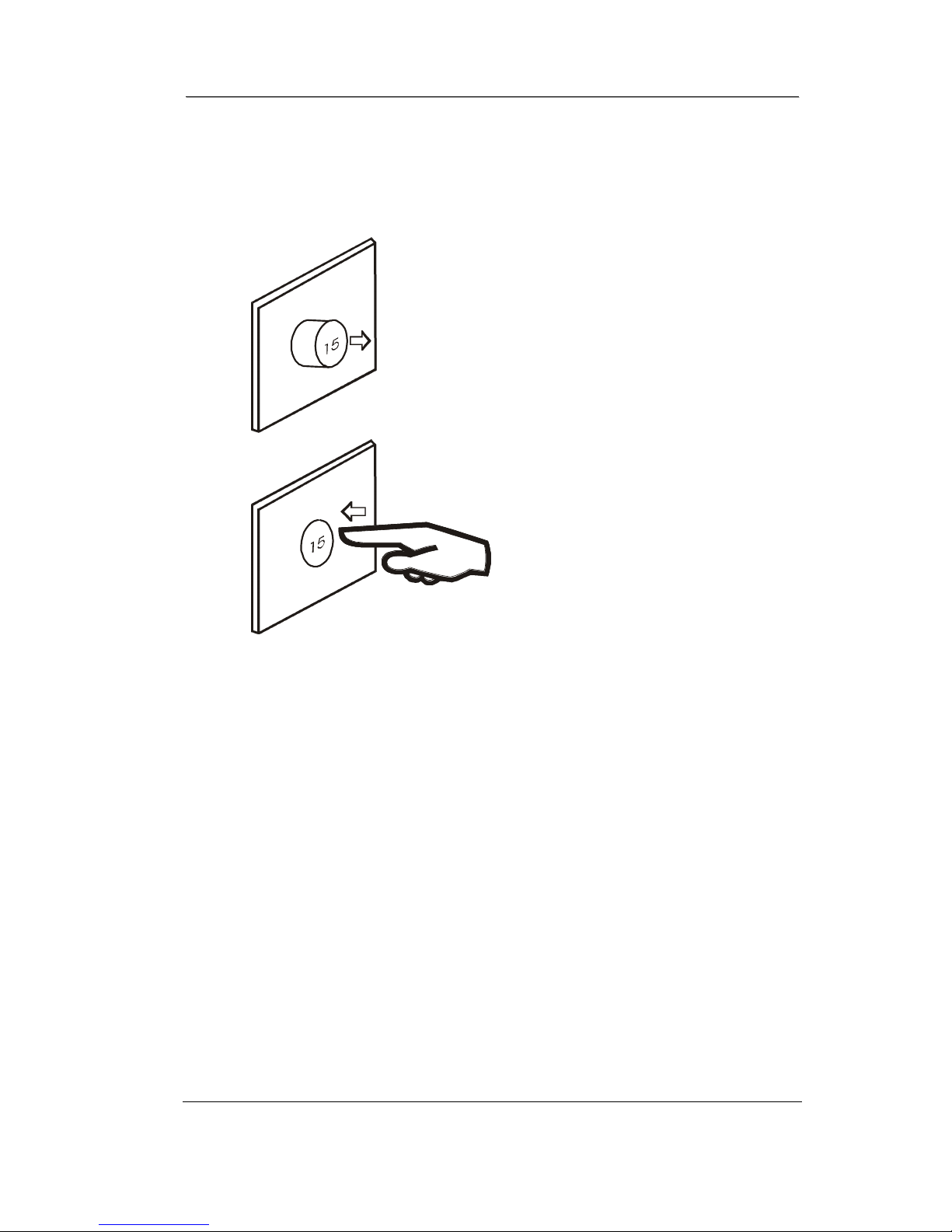
Figure 11 Resetting Reset switch
1. RESET SWITCH RESETTING
a) If the red button of reset switch is tripped, it will protrude
out from the face of the switch.
b) Press in the red button of the switch.
c) If the red button of reset switch is not tripped, that means
normal.
Tripped
Normal
Page 38
SSeerrvviicceeMMaannuuaall11662222773388TTrreeaaddmmiillllMMaauurriicceePPiinnccooffffssAAPPPPEENNDDIIXXDD11((888888))770077--1188880
0
AAPPPPEENNDDIIXXDD336
6
APPENDIX D
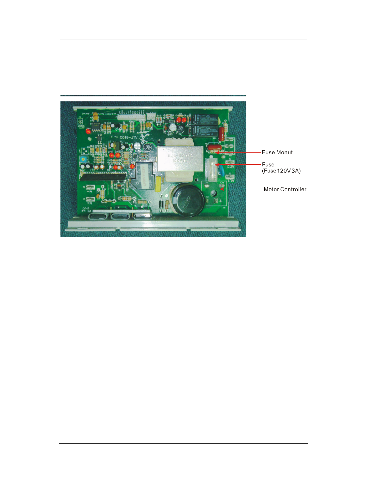
Figure 12 Fuse replacement
1. FUSE REPLACEMENT
If your treadmill loses power or will not start, check the fuse located on the
motor controller.
DANGER: Turn the power switch off and unplug the treadmill to reduce
the risk of an electric shock
Remove the motor cover
Remove and replace the fuse on the motor controller
Replace the motor cover
Page 39

SSeerrvviicceeMMaannuuaall11662222773388TTrreeaaddmmiillllMMaauurriicceePPiinnccooffffssAAPPPPEENNDDIIXXEE11((888888))770077--1188880
0
AAPPPPEENNDDIIXXEE337
7
APPENDIX E
1. SPEED SENSOR ADJUSTMENT
If the monitor does not display speed or distance the speed sensor and
magnet may be misaligned. Follow these steps to check and realign.
Remove the motor cover
Check the spacing and alignment between the magnet on the right side of
the front roller and the speed sensor on the frame. The spacing must be
1/8”.
Loosened screw and slide speed sensor in or out of clamp.
Retighten screw
Replace the motor cover.
2. SERVICE QUESTIONS
Contact: Maurice Pincoffs 1(888) 707-1880
!
 Loading...