


Introduction
[01 September 2006 - I've extensively revised this page to reflect the version 2.0 buffer
amplifier and to add a discussion on Elecraft K2 BFO leakage. I've deleted older material
no longer relevant.]
I've found a lot of interest in the SpectraScan panadapter from Elecraft K2 owners. The K2 has
a nominal IF frequency of 4914 KHz, and the SpectraScan works well at that frequency. (My
early Z90 design used an internal IF of 9830 KHz, and I built several experimental filters with
9830 KHz crystals. However, you may notice a relationship here -- 9830 KHz is almost exactly
double the K2's 4914 KHz IF. Internal birdies generated by this combination made me rethink
the SpectraScan's IF frequency and I changed to 8.000 MHz for K2 compatibility.)
Unlike some receivers and transceivers, the K2 does not have a IF output jack. Hence, it's
necessary to add an IF connection. I've designed a general purpose IF buffer amplifier that fits
within a fully-loaded K2.
The buffer amplifier can be built in two versions, by choice of components:
A version optimized for the K2, with a bandpass response, centered around 5 MHz for
the K2's 4915 KHz IF; or
A broadband version that will work with any IF from near DC to 100 MHz and is
accordingly not limited to just the K2.
Both versions share a common PCB, approximately 1.375" x 1.25" (35mm x 32mm). I will ship
the board with the parts necessary to build either the K2 version or the broadband version.
I also have designed a BNC-connector version of the broadband amplifier, but this seems to be
of little interest and it likely not become a finished product. If someone wants one or two, I can
make available a version without silk screening or solder mask.
Version 2.0 Buffer Amplifier with the Elecraft K2
Page 1 of 13
------------------------------------------------------------------------------------------------------
Phone: (800) 777-0703 Technical Support and International: (330) 572-3200 Fax: (330) 572-3279 E-mail: DXEngineering@DXEngineering.com
© 2017 - DX Engineering - 1200 Southeast Ave. - Tallmadge, OH 44278

Connection Point in the K2
The
schematic
fragment
shows the
recommended
connection
point.
The circuit
impedance at
this point is
relatively low,
on the order
of 150 ohms,
so the buffer
amplifier's
input
impedance
will result in
minimum
disturbance of
the K2's
operation.
Prototype Buffer Amplifier
I've designed and built a generic high impedance buffer amplifier. In this context, high
impedance is a relative term; my target was to get the input impedance in the several kohm
range over a frequency range of up to 75 MHz, and to have the possibility of gain ranging from 6 dB up to 10 to 15 dB. The target impedance range should permit a non-disturbing connection
to most receivers.
Of course, a higher impedance design is possible, such as an emitter follower or source
follower, with an additional gain stage. After building up several prototypes, I decided to go with
the AD8007 device.
The net gain is adjustable by a single programming resistor, from negative 6 dB to positive 12
dB or more. The gain will be set by the builder based on the receiver or transceiver with which it
is used. In testing the amplifier with a K2, the net gain (considering filter loss and other factors)
Page 2 of 13
------------------------------------------------------------------------------------------------------
© 2017 - DX Engineering - 1200 Southeast Ave. - Tallmadge, OH 44278
Phone: (800) 777-0703 Technical Support and International: (330) 572-3200 Fax: (330) 572-3279 E-mail: DXEngineering@DXEngineering.com

should be approximately 0 dB.
Power requirements: 12V @ 20 mA. The board has a 9V regulator and can operate with an
input voltage between 12V and 24V.
Here's a top view of version 1.1
of the buffer amplifier PCB. The
current version 2.0 is
essentially identical in the top
view.
Page 3 of 13
------------------------------------------------------------------------------------------------------
© 2017 - DX Engineering - 1200 Southeast Ave. - Tallmadge, OH 44278
Phone: (800) 777-0703 Technical Support and International: (330) 572-3200 Fax: (330) 572-3279 E-mail: DXEngineering@DXEngineering.com

Version 2.0, bottom view. The
components at the lower left
comprise a five-pole low pass
filter to shape the frequency
response.
This particular board was
assembled with plug-in
connectors for easier testing. I
do not recommend plug in
connectors at the buffer
amplifier board for installation
in a K2.
If assembled in "wideband"
mode, the response is is as
shown at the right--flat up to
about 30 MHz, where it starts
to peak. The 3 dB bandwidth
exceeds 300 MHz in this
configuration. At 4.914 MHz,
the net gain is +6.5 dB.
When measuring gain of a high
impedance amplifier with 50
ohm equipment, you must use
a 50 ohm through at the input,
or else you will see a false 6 dB
gain increase, as the source
voltage doubles into what is
nearly an open circuit with
respect to the 50 ohm source.
The gain data presented is with
a 50 ohm through termination
on the input.
------------------------------------------------------------------------------------------------------
Phone: (800) 777-0703 Technical Support and International: (330) 572-3200 Fax: (330) 572-3279 E-mail: DXEngineering@DXEngineering.com
Page 4 of 13
© 2017 - DX Engineering - 1200 Southeast Ave. - Tallmadge, OH 44278

Here's the frequency response
of the buffer amplifier when
assembled in the
recommended K2 bandpass
filter configuration.
At the K2's IF frequency, the
response is flat over the Z90's
200 KHz range.
------------------------------------------------------------------------------------------------------
Phone: (800) 777-0703 Technical Support and International: (330) 572-3200 Fax: (330) 572-3279 E-mail: DXEngineering@DXEngineering.com
Page 5 of 13
© 2017 - DX Engineering - 1200 Southeast Ave. - Tallmadge, OH 44278

Connecting the buffer to the K2
How the buffer amplifier is connected to the K2 depends on whether the K2 has the optional
noise blanker board.
Stan Rife, W5EWA, has been very helpful in working through an elegant mounting and
connection arrangement for the K2 buffer amplifier board.
The buffer board's input wiring consists of a short length of Teflon coaxial cable, and a single
piece of hookup wire for power. These wires terminate in a standard 3-pin 0.1" spaced male
header plug, insulated with heat shrink tubing.
If the Noise Blanker is not
Installed:
The buffer board will come with an 8-position 0.1" female
header socket, to be installed at J12. This is the same header
socket Elecraft provides with the noise blanker kit, so if you
decide to add the noise blanker kit later, you will not have to
remove any parts associated with the buffer board.
The 3-pin plug from the buffer amplifier plugs into the J12
socket at pins 1, 2 and 3.
If the Optional Noise Blanker
is Installed
Remove the noise blanker
board and turn it upside down.
Page 6 of 13
------------------------------------------------------------------------------------------------------
© 2017 - DX Engineering - 1200 Southeast Ave. - Tallmadge, OH 44278
Phone: (800) 777-0703 Technical Support and International: (330) 572-3200 Fax: (330) 572-3279 E-mail: DXEngineering@DXEngineering.com

With an X-Acto knife, trim away
the plastic from the male
header pins 1, 2 and 3, leaving
the pins soldered in place.
Solder the provided 3-pin
female header socket to the
three header pins, with the
socket parallel to the noise
blanker PCB.
Another view of how the threepin socket is solder to the
modified noise blanker header.
The 3-pin lead from the buffer board plugs into the newly added 3-pin socket.
Page 7 of 13
------------------------------------------------------------------------------------------------------
© 2017 - DX Engineering - 1200 Southeast Ave. - Tallmadge, OH 44278
Phone: (800) 777-0703 Technical Support and International: (330) 572-3200 Fax: (330) 572-3279 E-mail: DXEngineering@DXEngineering.com

Update on Testing with the K2
A prototype version 2.0 PCB
installed in my K2. The board
requires a small notch to fit
against the noise blanker, but
I'll move the mounting hole for
the next revision to avoid a
notched board.
The board is mounted with a 440 male/female threaded
stand-off in an existing hole.
I've made the input and output
coaxial cables longer than
desirable so that I might
experiment with alternative
mounting locations.
Close up of the output cable.
The cable terminates in an
SMA cable jack bulkhead
connector. The cable remains
shielded in the connector.
------------------------------------------------------------------------------------------------------
Phone: (800) 777-0703 Technical Support and International: (330) 572-3200 Fax: (330) 572-3279 E-mail: DXEngineering@DXEngineering.com
Page 8 of 13
© 2017 - DX Engineering - 1200 Southeast Ave. - Tallmadge, OH 44278

The output SMA connector
installed in a spare hole in my
K2. If you have no spare holes,
the SMA connector mounts in a
0.250" (6.35 mm) diameter
hole.
Here's a view of the 20 meter
band, from 14000 - 14200 KHz,
as seen via my K2 connected
to a prototype Z91 via the
prototype version 2.0 buffer
amplifier.
BFO Leakage
Stan, W5EWA, reported seeing a steady signal displayed on the Z90, even with no antenna
connected to his K2, but it was not clear if this signal was an aberration in his particular K2, or if
it will be generally seen in all K2 transceivers.
I'm seeing the same signal, and it appears that it is BFO leakage through the reverse gain of the
Page 9 of 13
------------------------------------------------------------------------------------------------------
© 2017 - DX Engineering - 1200 Southeast Ave. - Tallmadge, OH 44278
Phone: (800) 777-0703 Technical Support and International: (330) 572-3200 Fax: (330) 572-3279 E-mail: DXEngineering@DXEngineering.com

IF system. The BFO leakage level is approximately -80 dBm as seen at the IF pick-off point.
Whether the BFO leakage signal will be a problem depends on your perception. Here's what I've
found with my K2, and Stan's results are similar.
The Z90/91 display, connected
to a K2 with the buffer amplifier
and with no antenna connected
to the K2. This is the worstcase for the BFO leakage
signal, as there are no other
signals to be seen on the
panadapter. I've also selected
a narrow span which
exaggerates the BFO leakage
signal.
The BFO signal is about 25 dB
above the Z90's noise floor.
To verify that the BFO leakage
is not an artifact of the Z90, I
observed the same signal with
an HP8558B spectrum
analyzer.
Page 10 of 13
------------------------------------------------------------------------------------------------------
© 2017 - DX Engineering - 1200 Southeast Ave. - Tallmadge, OH 44278
Phone: (800) 777-0703 Technical Support and International: (330) 572-3200 Fax: (330) 572-3279 E-mail: DXEngineering@DXEngineering.com

In normal operation, the BFO
leakage is much less visible.
This shot shows the same
frequency, but with a wider
span and an antenna
connected to the K2, with the
K2's pre-amplifier turned on.
Narrow span (10 KHz),
antenna connected but K2 preamplifier off. The BFO leakage
is noticeable.
Where does the BFO leakage come from?
It seems that the BFO signal is passed back to the buffer amplifier's input via one of two
possible paths, as illustrated in the marked-up K2 block diagram below.
Page 11 of 13
------------------------------------------------------------------------------------------------------
© 2017 - DX Engineering - 1200 Southeast Ave. - Tallmadge, OH 44278
Phone: (800) 777-0703 Technical Support and International: (330) 572-3200 Fax: (330) 572-3279 E-mail: DXEngineering@DXEngineering.com
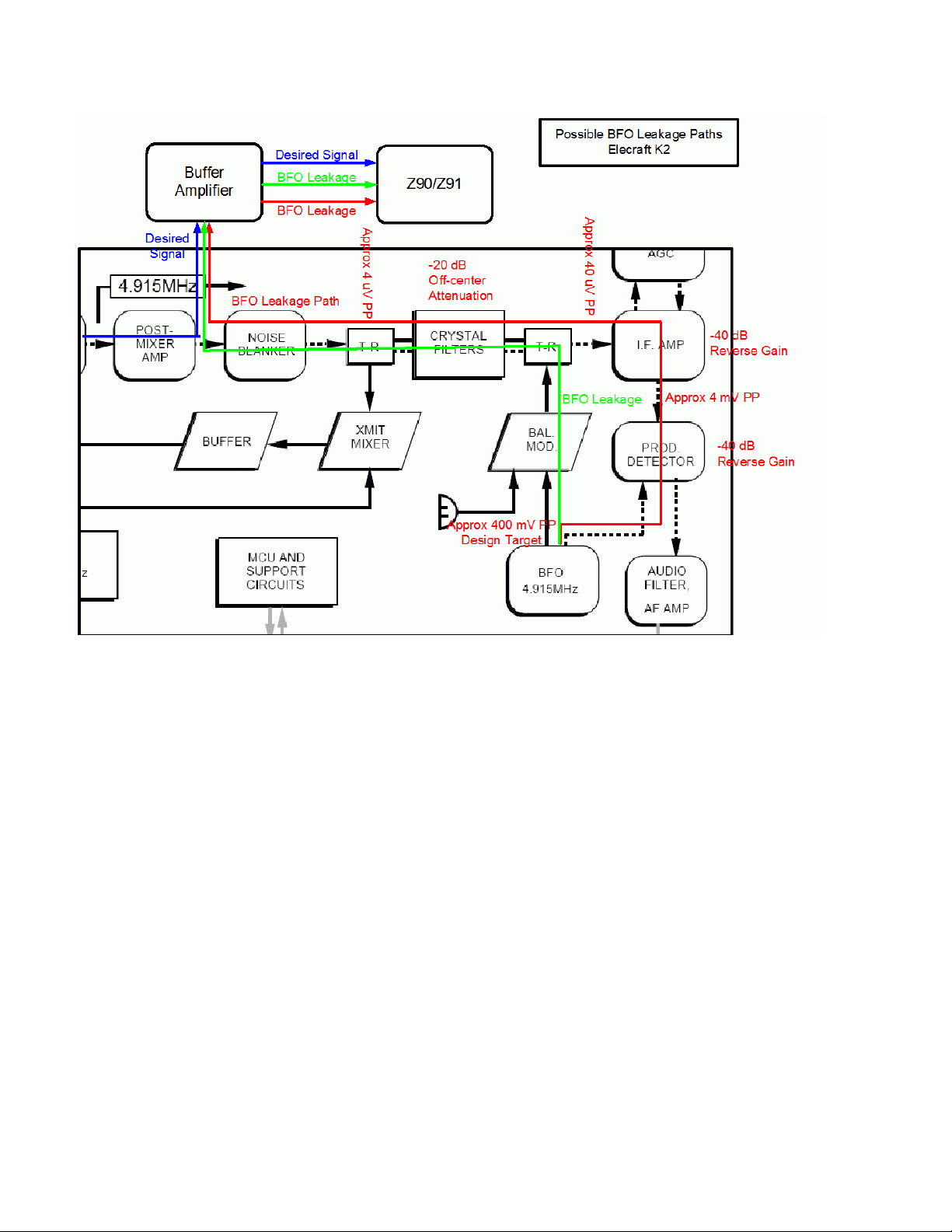
It's not clear which of the two possible paths is the culprit. Considering that the BFO signal is
quite strong (I measured nearly 2 volts peak-to-peak at U11), even if it is attenuated 90 dB, it
still shows up as a clearly visible signal at the IF pick-off point.
I've tried alternative buffer board locations, and the BFO leakage signal remains the same,
which indicates the problem is unlikely to be stray coupling into the buffer amplifier. Rather, the
BFO leakage is directly in the signal chain. (I've had E-mail exchanges with Wayne Burdick at
Elecraft confirming this is the likely source of the signal.)
Why does the K2 have BFO leakage but other transceivers do not?
Several possible reasons:
The K2 is a single-conversion design, and hence the BFO is at the same frequency as
the point where we sample the IF frequency. A multiple conversion receiver will not have
the BFO on the same frequency as the high IF.
Relatively simple IF chain. There are only two active stages between the IF pick-off point
Page 12 of 13
------------------------------------------------------------------------------------------------------
© 2017 - DX Engineering - 1200 Southeast Ave. - Tallmadge, OH 44278
Phone: (800) 777-0703 Technical Support and International: (330) 572-3200 Fax: (330) 572-3279 E-mail: DXEngineering@DXEngineering.com

and the BFO. Thus, the BFO suppression is critically dependent upon (a) U11 (NE602)
balance and the reverse gain of U12 (MC1350) IF amplifier. If both U11 and U12 have 40 dB reverse gain (how strong the signal at the amplifier's input is when fed into the
output), the BFO will be attenuated only 80 dB at the IF sample pickup point. Other
receivers have more IF amplification stages, which improves the overall BFO leakage
proportionally.
Single board construction. At one extreme, commercial and military grade receivers have
each major module constructed in a separate, shielded compartment. The K2 has all its
RF components on a single PCB. This provides a significant cost benefit, but may
contribute to the BFO leakage.
If you tap off an IF stage operating at the same frequency the BFO, you may well see
BFO leakage.
Why Doesn't the BFO Leakage Bother Normal Receiver Operation?
Because it is at the same frequency as the BFO and because it is much weaker than the direct
signal. The leakage that shows up on the Z90 panadapter (and on my HP8558B spectrum
analyzer) will have no effect upon normal K2 operation.
How to Remove the BFO Leakage Signal?
The most promising method is to move the buffer amplifier connection point from the
recommended output of Q22 to Q22's input, i.e., to the mixer output, at the junction of C159,
R80 and R81. This will decrease the BFO leakage signal by Q22's reverse gain.
The problems with connecting at the mixer output are:
Less gain, as Q22 will not be in the circuit. The buffer amplifier gain can be increased to
offset this loss to some extent.
Much less mechanically convenient, as the suggested connection point is not brought out
to a convenient jack.
Since Q22 has a lot of negative feedback, its reverse gain may not be as high as desired,
and the degree of BFO leakage suppression correspondingly modest.
------------------------------------------------------------------------------------------------------
© 2017 - DX Engineering - 1200 Southeast Ave. - Tallmadge, OH 44278
Phone: (800) 777-0703 Technical Support and International: (330) 572-3200 Fax: (330) 572-3279 E-mail: DXEngineering@DXEngineering.com
Page 13 of 13
 Loading...