

Page 1

Multi-Band Dipole Kit
DXE-WA-070 40-10 Meters
DXE-WA-135 80-10 Meters
DXE-WA-260 160-10 Meters
DXE-WA-INS-Series Rev 4a
1200 Southeast Ave. - Tallmadge, OH 44278 USA
Phone: (800) 777-0703 ∙ Tech Support and International: (330) 572-3200
Fax: (330) 572-3279 ∙ E-mail: [email protected]
DX Engineering 2020
Page - 1 -
Page 2

Introduction
Part Number
Length in Feet
Band Coverage
DXE-WA-70
70
40M through 10M*
DXE-WA-135
135
80M through 10M*
DXE-WA-260
260
160M through 10M*
The DX Engineering Multi-Band Dipoles are designed to be rugged yet lightweight. Using a tuner, they are
usable to 30 MHz. They come complete with the extra length wire elements, 100 feet of premium 300 Ω
ladder feedline, Center-T support (U.S. Patent No. 7,764,244), and end mounting insulators (U.S. Patent No.
D534,905). All hardware is stainless steel.
Dipole Models
There are 3 configurations. Depending on the tuner used, each model can be used at the low end of the
respective 40, 80 or 160m band through 30 MHz:
* Band coverage depends on location of the antenna, the use of a wide range
tuner and the appropriate DX Engineering balun designed for use with an
antenna tuner.
Specifications
All DX Engineering Multi-Band Dipole Antennas are built using the highest quality components.
Elements - 14 AWG stranded copper, black PVC jacket for flexibility and strength
Feedline - 18 AWG stranded, 300 Ω ladder line, UV-resistant, 0.88 Velocity Factor
Hardware - Stainless steel
Center-T support and end-insulators - Black, high impact, and UV-resistant
Power rating - The correct DX Engineering 1:1 Current Balun is DXE-MC20-1-1 for one band
resonant or DXE-MC20-1-1T for multi-band using a Tuner. These baluns provide better balance, have
lower loss, and are more tolerant to load impedance and balance variations than other baluns. the
limiting factor in band coverage will be the height above ground, location and the tuner used.
Safety Considerations
WARNING!
INSTALLATION OF ANY ANTENNA NEAR POWER LINES IS DANGEROUS
Warning: Do not locate the antenna near overhead power lines or other electric light or power circuits, or
where it can come into contact with such circuits. When installing the antenna, take extreme care not to
come into contact with such circuits, because they may cause serious injury or death.
Overhead Power Line Safety
Before you begin working, check carefully for overhead power lines in the area you will be working. Don't
assume that wires are telephone or cable lines: check with your electric utility for advice. Although overhead
power lines may appear to be insulated, often these coverings are intended only to protect metal wires from
weather conditions and may not protect you from electric shock
Keep your distance! Remember the 10-foot rule: When carrying and using ladders and other long tools, keep
them at least 10 feet away from all overhead lines - including any lines from the power pole to your home.
Page - 2 -
Page 3

Mounting Considerations
When planning the location of your antenna, consideration should be given to the height, location of suitable
support structures and feedline positioning and length.
Generally speaking, these antennas should be mounted as high as possible for best performance. Antenna
height will affect the exact resonance point, radiation pattern, and takeoff angle. The higher the antenna, the
lower the takeoff angle to the horizon, which increases the effective range of the antenna.
For DX, the minimum height above ground should be 1/2-to 1-wavelength at the lowest operating frequency.
On the low bands, this height becomes impractical for most hams. For example, an 80m dipole at 70 feet is
about 1/4-wavelength above the ground. This antenna would be good for local and short distance
communications, but not optimal for DX, due to the high takeoff angle and ground absorption. A 40M dipole
at 70 feet is approximately 1/2-wavelength high and is likely to be good for DX and less optimal for local or
short range communications. For more information on antenna design, feedline and radiation angles, consult
a reliable text such as the ARRL Antenna Book.
The antenna, including the 300 Ω feedline, should also be mounted as far from other structures as possible.
This includes the ends of the wire elements, which are actually the most sensitive part of the antenna. Any
objects, metal in particular, within the near-field radiation pattern can affect the impedance and radiation
pattern of the antenna.
The feedline should also come away from the antenna at right angles for at least 1/2-wavelength for best
performance.
Most installations involve compromises due to local terrain, available supporting structures, or other
restrictions. Do the best you can with what you have.
Multi-Band Center Fed Shortened Dipole using Ladder Line Feedline
The DX Engineering Multi-Band Dipoles include 100 feet of high quality legal limit capable 300 Ω ladder
line. Depending on your specific installation, this feedline will need to be shortened or lengthened. The
optional DXE-LLC-1P Ladder Line Couplers can be used for connecting ladder line together for
lengthening the ladder line.
Also included are two rolls of element wire, a hardware packet and four ring terminals. Two of the ring
terminals accommodate 14 gauge wire and are used for the elements. The smaller ring terminals
accommodate 18 gauge wire and are used for the ladder line.
Unroll the 2 wire elements and the ladder line using a hand-over-hand technique. This will prevent kinks and
allow the wires to lay flat for assembly.
The ladder line feedline should be installed in odd multiple lengths of 1/8-wavelength on the lowest
operating frequency to optimize the impedance presented to the balun over the frequency range of the
antenna. This length can be calculated using the formula shown above Table 1 or use Table 1. DX
Engineering 300 Ω ladder feedline has a velocity factor (VF) of 0.88.
If you have excess ladder line, it can be zigzagged while suspended in air, but it can't be closer than a few
conductor spacings to metallic objects and should not be coiled or laid on the ground. If it is necessary to
pass close to a metallic object, twist the line to partially balance the affect on both sides of the feedline.
If you need additional feedline, 100 ft. rolls (part number DXE-LL300-1C) and a convenient line coupler
(part number DXE-LLC-1P) are available from DX Engineering. The line coupler includes a high impact,
Page - 3 -
Page 4

insulated splice block, ring terminals and stainless hardware, permitting strong and consistent splices of
ladder line. See Figure 2.
Note: When using an external balun, the feedline length should be calculated from the Center-T ladder line
connection to the balun.
Often, a 4:1 balun is suggested for Multi-Band Dipoles. However, the best balun to use for this application
has a 1:1 ratio. The impedance at the end of the feedline will vary from very high to very low. Tuners have
an easier time with high impedance than a low one. A balun with a ratio of 4:1 or more will transform the
already low impedance to an even lower one that will make the antenna hard to tune. The 1:1 ratio balun will
just pass the low impedance through. Provide strain relief so the ladder line is not directly pulling on the
balun connections.
The correct DX Engineering 1:1 Current Balun is DXE-MC20-1-1 for one band resonant or DXE-MC20-1-
1T for multi-band using a Tuner. These baluns provide better balance, have lower loss, and are more tolerant
to load impedance and balance variations than other baluns.
Even when properly done, this arrangement will subject the coaxial line between the tuner and balun to very
high standing waves and high voltage and/or current. Keep the coaxial line length as short as possible. If an
externally mounted balun is not used, do not route the ladder line so close to the tuner or the rest of the
station cables and equipment that RF feedback occurs. This will manifest itself by making the antenna very
difficult to tune and the tuner controls will be very touchy. There may also be RF present on the microphone,
key, etc. At a minimum, use good low loss coaxial line like DXE-213U an RG-213 or equivalent. RG8X and
smaller coax will not do a proper job.
A simple multi-band dipole may be constructed for the lowest band on which operation is desired, but the
overall length of the dipole antenna should be a shortened half wavelength as shown in Table 1. This antenna
may be fed with ladder line and an antenna tuner with balanced connections. You should use a DX
Engineering external balun connected with coaxial cable to a wide range unbalanced tuner for tuning the
different bands.
Although it may not seem logical, shortening a multi-band dipole intended for 160 through 10 meter
operation to less than 220 Ft. will actually help your wide range antenna tuner cover the lower frequencies
easier. The same is true for a 80 through 10 meter coverage, shortened antenna to 110 ft. That is because you
are using a non-resonant antenna system when you use ladder line feed systems for multi-band operations.
Changing the length of the ladder line will alter resulting impedances so the tuner should be able to reach a
certain frequency that was giving it trouble. The coax from the DX Engineering 1:1 Balun to the tuner should
be kept short; typically 5 to 15 feet is best.
The DXE-LL300 - 300 Ω ladder feedline for a multi-band dipole must be close to an odd multiple length of
1/8 wavelength on the lowest operating frequency, used to optimize the impedance presented to the balun
and tuner over the frequency range of the antenna. This length can be calculated using the following formula
or use Table 1. The DX Engineering 300 Ω ladder feedline has a VF (Velocity Factor) of 0.88.
Formula:
Where: 123 = 1/8-Wavelength Factor, Freq = Frequency in MHz,
0.88 = Velocity Factor of DXE-LL300 300 Ω Ladder Feedline
Multiply the result times the odd multiple (1, 3, 5, 7, etc.) to get the correct length closest to your required
feedline length.
Page - 4 -
Page 5
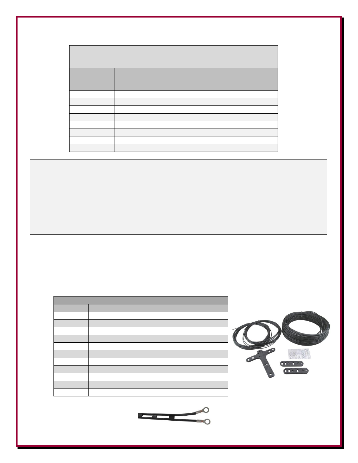
Table 1
Recommended Antenna and Feedline Length for
Shortened Multi-Band Dipoles for easier tuning
Frequency
(MHz)
Shortened
Dipole (Ft.)
Make feedline an Odd Multiple of
or close to this length
in Feet (x 1, 3, 5, etc.)
1.8
220
60
3.5
110
31
5.3
76
20
7
55
15
10.1
41
11
14
29
8
18
22
6
21
19
5
Example: To use an antenna from 80 meters to 10 meters, the feedline should be in odd 1/8 wavelength
multiples on 80 meters.
The 80 meter band starts at 3.5 MHz. Therefore, 123/3.5 = 35.1.
DX Engineering 300 ohm ladder line has a velocity factor (VF) of 0.88, so 35.1 x 0.88 = 30.9 ft. per 1/8wavelength.
If 90 feet is required to get to your balun mounting position, the nearest odd multiple 1/8 wavelength length is
92.7 feet (30.9 x 3).
If you need over 100 feet, you would have to add to the feedline to achieve 154.5 feet (30.9 x 5) to maintain the
odd 1/8th multiple rule for length of the DX Engineering 300 ohm ladder line.
Kit Contents
Qty
Description
1
Ladder Line Center “T”
2
End Insulator
2
Element Wire (length depends on model)
1
Ladder Line, 100 Ft.
2
Ring Terminal - 14 ga. - #10 hole
2
Ring Terminal - 18 ga. - #10 hole
4
Flat Washer, #10
2
Split Lock Washer, #10
2
External Tooth Lock Washer, #10
2
Hex Head Bolt, 10-24 x 3/4”
4
Hex Head Nut, 10-24
Assembling the Dipole
Center-T Support
The Center-T support has pre-drilled holes for attachment of the wire elements, ladder line feedline, and a
support or messenger line.
Install two the two 18 ga. Ring Terminals on one end of the ladder line. Crimping works fine,
soldering is optional.
Page - 5 -
Page 6
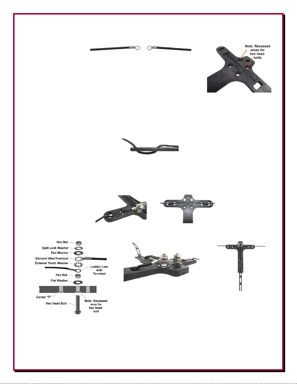
Install one 14 ga. Ring Terminal on each of the wire lengths at one end. Crimping works fine,
soldering is optional.
Install the Hex Head Bolts into the two upper holes in the Center-T. Note
one side of the Center-T has recessed areas for the hex head on the bolts.
Install a flat washer and then a hex nut on each of the hex head bolts and tighten. Refer to Figure 1
for a picture showing the hardware installed.
Weave the end of the ladder line with the attached Ring Terminals through the Center-T as shown
in and place the ring terminals on the hex head bolts. Remove the excess slack in the ladder line on
the Center-T support prior to putting up the antenna.
Install external tooth lock washers over the ladder line terminals.
Weave the ends of the element wires with ring terminals through the Center-T as shown and place
the ring terminals on the hex head bolts. Remove the excess slack in the wire elements on the
Center-T support prior to putting up the antenna.
Install flat washers on top of the element ring terminals. Install split lock washers on top of the flat
washers. Finally install hex nuts on top of the split lock washers and tighten the assembly.
Figure 1 - Center-T Support Hardware Stack,
DX Engineering Logo Facing Up
Ladder Line Length
Determine the length of ladder line needed for your particular antenna design. Refer to Table 1 for details on
ladder line lengths.
Page - 6 -
Page 7
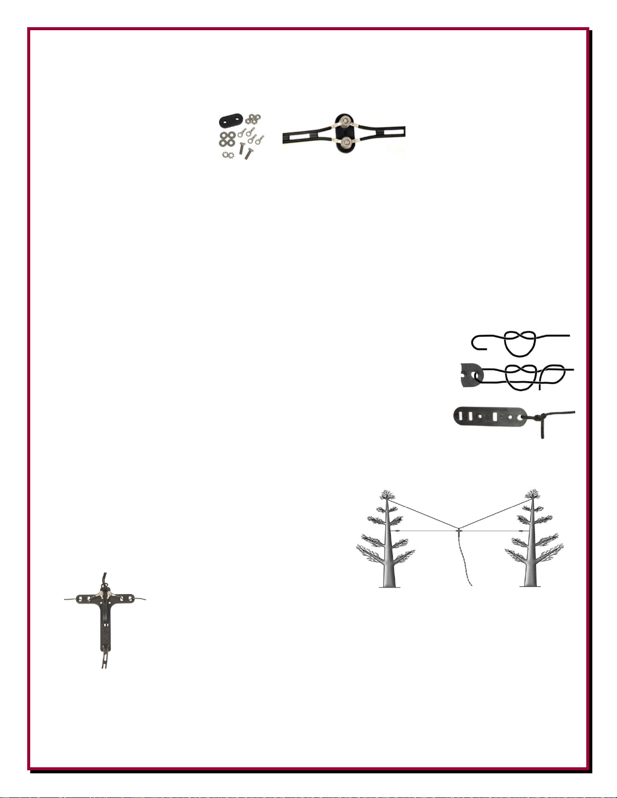
If you need additional feedline, the optional DX Engineering DXE-LLC-1P Ladder Line Coupler can be
used to create a strong and consistent splice. See Figure 2.
Figure 2 - DXE-LLC-1P Line Coupler
Element Wire Lengths
Determine the length of the element wires needed for your particular antenna design. Refer to Table 1 for
details on element wire lengths.
Attaching UV Resistant Rope to the End Insulators
UV resistant Rope should be secured to the Center-T and/or the End Insulators
(depending on your installation) using a non-slip knot. One suggestion for attaching
the rope is shown in Figure 4. The ends of the rope should be cauterized with a small
flame to prevent the rope braid from fraying.
Figure 4 - Non-Slip Knot using UV resistant Rope
Support Line
The center-T support top hole is used for the attachment of a
UV resistant “messenger line” that can be strung above the
antenna wire and is used to provide support for the antenna
wire and feedline. The use of the messenger line, which is
strongly recommended, will reduce stress on the element wires
and keep the antenna from stretching over time, which will
change its resonant frequency.
Determine the required length for the
messenger line. Ideally, it should attach to the same structure used for the dipole, only
above it, forming at least a 30 degree angle between the dipole and the messenger line.
The ends of the rope should be cauterized with a small flame to prevent the rope braid
from fraying.
After determining the proper length needed, form a loop at the mid-point of the
messenger rope. Push this loop through the center-T support top hole, then pull the rest of the rope through
the loop.
Page - 7 -
Page 8

Manual Updates and Information
Every effort is made to supply the latest manual revision with each product. Occasionally a manual will be
updated between the time your DX Engineering product is shipped and when you receive it. Please check the
DX Engineering web site (www.dxengineering.com) for the latest revision manual.
Technical Support
If you have questions about this product, or if you experience difficulties during the installation, contact DX
Engineering at (330) 572-3200. You can also e-mail us at: [email protected]
For best service, please take a few minutes to review this manual before you call.
Warranty
All products manufactured by DX Engineering are warranted to be free from defects in material and workmanship for a period of one (1) year from
date of shipment. DX Engineering’s sole obligation under these warranties shall be to issue credit, repair or replace any ite m or part thereof which is
proved to be other than as warranted; no allowance shall be made for any labor charges of Buyer for replacement of parts, adjustment or repairs, or
any other work, unless such charges are authorized in advance by DX Engineering. If DX Engineering’s products are claimed to be defective in
material or workmanship, DX Engineering shall, upon prompt notice thereof, issue shipping instructions for return to DX Engineering (transportationcharges prepaid by Buyer). Every such claim for breach of these warranties shall be deemed to be waived by Buyer unless made in writing. The above
warranties shall not extend to any products or parts thereof which have been subjected to any misuse or neglect, damaged by accident, rendered
defective by reason of improper installation, damaged from severe weather including floods, or abnormal environmental conditions such as prolonged
exposure to corrosives or power surges, or by the performance of repairs or alterations outside of our plant, and shall not apply to any goods or parts
thereof furnished by Buyer or acquired from others at Buyer’s specifications. In addition, DX Engineering’s warranties do not extend to other
equipment and parts manufactured by others except to the extent of the original manufacturer’s warranty to DX Engineering. The obligations under
the foregoing warranties are limited to the precise terms thereof. These warranties provide exclusive remedies, expressly in lieu of all other remedies
including claims for special or consequential damages. SELLER NEITHER MAKES NOR ASSUMES ANY OTHER WARRANTY
WHATSOEVER, WHETHER EXPRESS, STATUTORY, OR IMPLIED, INCLUDING WARRANTIES OF MERCHANTABILITY AND
FITNESS, AND NO PERSON IS AUTHORIZED TO ASSUME FOR DX ENGINEERING ANY OBLIGATION OR LIABILITY NOT STRICTLY
IN ACCORDANCE WITH THE FOREGOING.
©DX Engineering 2020
DX Engineering®, DXE®, DX Engineering, Inc.®, Hot Rodz®, Maxi-Core®, DX Engineering THUNDERBOLTv, DX Engineering Yagi Mechanical®,
EZ-BUILD®, TELREX®, Gorilla Grip® Stainless Steel Boom Clamps, Butternut®, SkyHawk™, SkyLark™, SecureMount™, OMNI-TILT™, RFPRO-1B®, AFHD-4® are trademarks of PDS Electronics, Inc. No license to use or reproduce any of these trademarks or other trademarks is given or
implied. All other brands and product names are the trademarks of their respective owners.
Specifications subject to change without notice.
Page - 8 -
 Loading...