


DX Engineering
Super Duty+ Pivot Base for Four Inch
Base Section Vertical Antennas
DXE-VA-PIVOT-4
US Patent No. 8,130,168
DXE-VA-PIVOT-4-INS Revision 0
Shown with Customer Supplied Mounting Pipe
© DX Engineering 2012
P.O. Box 1491 ∙ Akron, OH 44309-1491 USA
Phone: (800) 777-0703 ∙ Tech Support and International: (330) 572-3200
Fax: (330) 572-3279 ∙ E-mail: DXEngineering@DXEngineering.com
Introduction
Congratulations on obtaining your DX Engineering Four Inch Super Duty+ Base Pivot Assembly
DXE-VA-Pivot-4. Now you can have a high-performance pivot base for a vertical antenna with a
four inch base section. This is the same super duty pivot base assembly used on the DXE-
7580FSVA-3 sixty-seven foot tall vertical antenna.
Features
High Strength Super Duty Plus Pivoting Fixture - US Patent No. 8,130,168
Ultra-rugged construction for vertical antennas starting with 4 inch OD heavy wall tubing
Massive Extren® channel insulator
Laser-cut high strength Stainless Steel brackets
All Stainless Steel Hardware
The optional DXE-VRW-1 Manual Winch for easy one-person raising and lowering of your
vertical antenna is available from DX Engineering. You can move the DXE-VRW-1 winch
between similar antennas in a multi-antenna installation.
This heavy duty pivot base system requires a heavy duty mounting pipe. Recommended installation
should provide up to 3" OD heavy wall galvanized steel pipe set in concrete. Schedule 80 pipe that
is called 2-1/2" has an outside diameter of 2.875" is recommended. 36" of the mounting pipe should
extend above ground level. Depth of the mounting hole and amount of concrete is dependent on
your antenna design, local soil type and antenna guying.
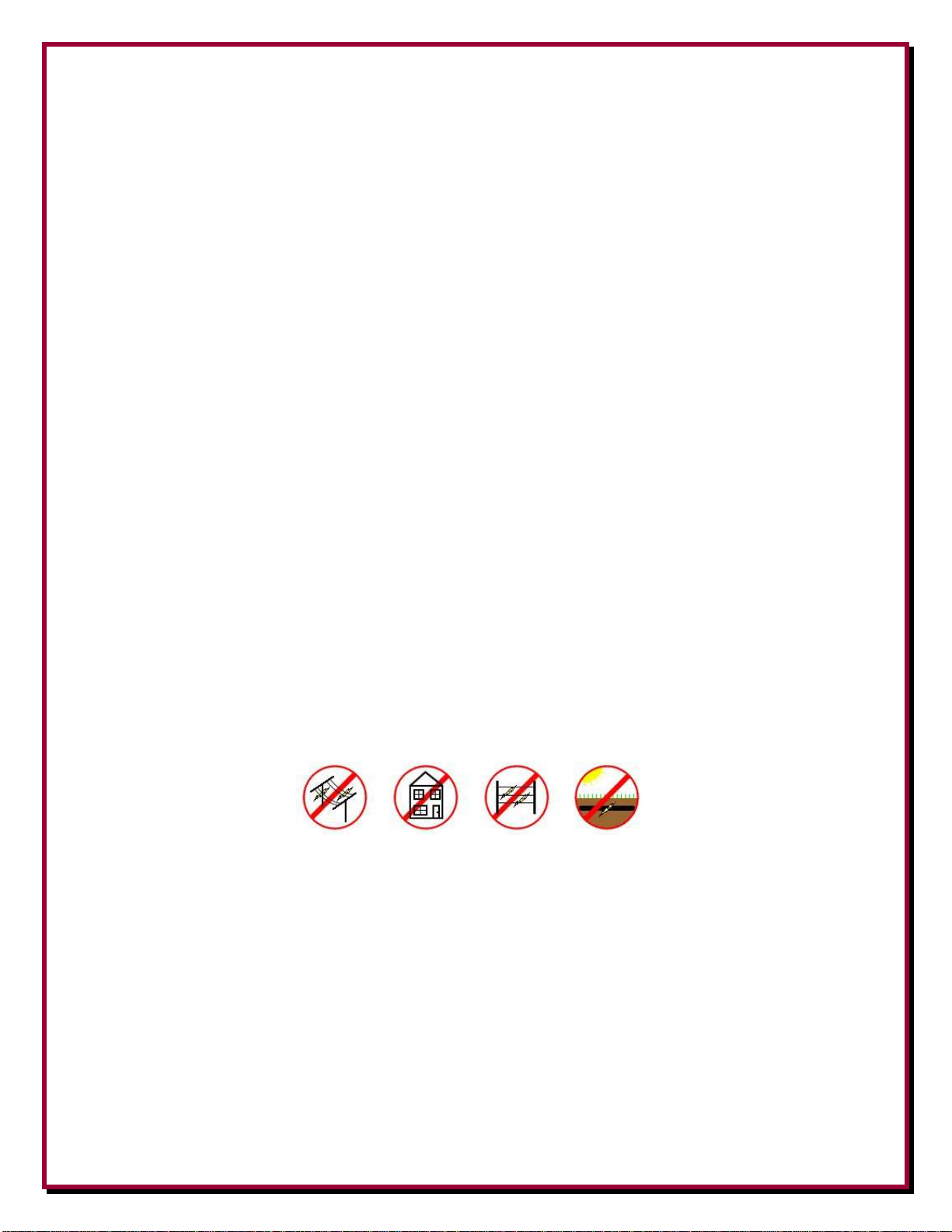
WARNING!
INSTALLATION OF ANY ANTENNA NEAR POWER LINES IS DANGEROUS
Warning: Do not locate the antenna near overhead power lines or other electric light or power
circuits, or where it can come into contact with such circuits. When installing the antenna, take
extreme care not to come into contact with such circuits, because they may cause serious injury or
death. Keep your distance! Remember the 10-foot rule: When carrying and using ladders and other
long tools, keep them at least 10 feet away from all overhead lines - including any lines from the
power pole to your home.
Tools Required
Two 9/16" wrenches, (one of them should be open-end)
One 7/16" open end wrench
One 1/2” wrench
Two 3/4" wrenches
- 1 -

Manual Updates and Information
Every effort is made to supply the latest manual revision with each product. Occasionally a manual
will be updated between the time your DX Engineering product is shipped and when you receive it.
Please check the DX Engineering web site (www.dxengineering.com) for the latest revision manual.
Please - Take the time to read the entire manual before you start assembly. There are plenty of
pictures and drawings to see, and if you read the entire manual first, you'll get a better feel for the
overall construction methods described. Assembly is not difficult, but there are a number of parts
that must go together in a certain sequence to make assembly easier.
Installation Sequence
1. Site Selection
2. Mounting Pipe
3. Coaxial Cable to Mounting Pipe
4. Radial System Suggestions
5. Pivot Base Assembly (US Patent No. 8,130,168)
6. Mounting Pivot Base to Mounting Pipe
7. Optional DXE-VRW-1 Manual Winch installation and use
Site Selection
Select a mounting location clear from power lines, structures and other antennas by a minimum of
78 feet (68 + 10 ft safety rule). Consider overhead power lines, utility cables and wires. The
further away the vertical is mounted from local noise sources or other metallic objects, which can
re-radiate noise and affect the tuning, radiation pattern and SWR, the better. Determine the direction
you want the antenna to pivot and make sure there is adequate clearance (at least 80 feet).
Mounting Pipe
Use a customer supplied 2-1/2" schedule 80, which has an outside diameter (OD) of 2.895",
galvanized steel thick-walled mounting pipe at least 7-1/2 feet long. This will allow approximately
4-1/2 feet below ground and 37 inches above ground.
Some manufacturers use the term DOM (drawn over mandrel) which will give you a true OD
dimension. Other types of mounting pipe may be used but due to lateral strength needed ensure the
mounting pipe is strong enough. The material most available is ASTM A513 Type 5 which is a
1020 material. Some pipe suppliers list the material as either 1020 or 1026. Type 1020 has the
following properties:
ASTM A513 (1020): Up to 2-3/4" OD with maximum wall thickness of 0.25"
Tensile: 80,000 PSI. Yield: 70,000 PSI. Elongation in 2": 15%. Rockwell Hardness: B80
ASTM A513 (1020): Over 2-3/4" OD with wall thickness heavier than 0.25"
Tensile: 70,000 PSI. Yield: 60,000 PSI. Elongation in 2": 20%. Rockwell Hardness: B80
3.00" OD x 0.25" wall thickness (or more) of 65,000 PSI yield tubing may also be used.
- 2 -

Depending on your geographic location, various dealers should be able to supply the mounting post
you specify. The following dealers can supply DOM tubing: (Other dealers in your area may be a
better choice.)
Industrial Tube & Steel, Corp.: www.industrialtube.com
On Line Metal Store: www.onlinemetals.com
Speedy Metals: www.speedymetals.com
Note: DX Engineering does not recommend or endorse any specific vendor.
Metals Depot: www.metalsdepot.com
This mounting pipe must be permanently mounted in the
ground, preferably in a concrete base 2 feet by 2 feet by 4
feet deep (with gravel below for drainage). The antenna
system requires this type of mounting to help withstand the
lateral forces present on the antenna during wind
conditions and when operating the pivot function. Make the
hole deep enough to accommodate at least 4 feet of pipe
and 4 to 6 inches of gravel at the bottom for drainage. Set
the mounting pipe on the gravel, use the concrete to fill
around the pipe per the concrete instructions. Fill the hole
until the concrete is level with the ground around it. Use a
level on the mounting pipe as you fill the hole to be sure
the mounting pipe is vertically straight.
Your location, landscape and ground conditions may
require different mounting solutions in order to have the
steel mounting pipe and the vertical antenna in a secure
position.
Coaxial Cable to Mounting Pipe
The coaxial cable should be routed to the base of the antenna system and be buried below the radial
system. PVC Conduit pipe may be used to house the coaxial cable. Bury the cable 6" to 12" below
ground level.
Radial System Suggestions
The use of a radial system is a key requirement for any high performance quarter wave vertical
antenna system. With a vertical antenna system, the radials are the second half
of the antenna. The radials contribute to the radiation efficiency of the entire
vertical antenna system.
At a minimum, 32 radials, each 65 feet long, should be used with most low
band vertical antennas. DXE-RADW Radial Wire, a 14 gauge stranded copper
with a black relaxed PVC insulation wire is suggested for the best results.
The wire radials should placed as symmetrically as possible straight from the
- 3 -

feedpoint around the vertical antenna and spaced evenly, regardless of how many radials are used.
Note: UMI-81343 Never-Seez® or DXE-NSBT8 Anti-Seize should be used on all stainless
steel threaded hardware to prevent galling and to ensure proper tightening.
Do not cross or bunch any radial wires as this nullifies their effectiveness. If you have limited space,
put in as many straight radials as you can. The radials must be connected to the shield of your
feedline. The DXE-RADP-3 Stainless Steel Radial Plate is an ideal optional item which provides
an excellent system for attaching radial wires to your vertical antenna system feedpoint.
Radial wires can be laid on the roots of the grass using DXE-STPL Radial Wire Anchor Pins to
hold them down. Using enough staples will ensure the wires will not be snagged by mowers,
people, or animals. Grass will quickly overgrow the radials and it will be virtually impossible to see
them. An article describing this process is available on the DX Engineering website. Radials can
also be buried just under the surface by using a power edger to make a slit in the soil.
Note: The following assembly instructions are based on using a customer supplied
2.895" OD Mounting Pipe (referred to as 3” OD), with the optional DXE-
VRW-1 Manual Winch, optional DXE-RADP-3 Radial Plate with one
optional DXE-SSVC-3P V Clamp and the optional DXE-112 Chassis Mount
Coaxial Cable Fitting.
- 4 -

Radial Plate to Mounting Pipe
Place the optional DXE-RADP-3 Radial Plate over the 2.895" OD mounting pipe. Connections to
the antenna will be made via the optional DXE-363-SST bulkhead fitting SO-239 socket connector.
The DXE-RADP-3 Radial Plate comes with 20 sets of stainless steel hardware for mounting the
radial wires. It is suggested that 32 radial each 65 feet long be used, therefore additional DXE-
RADP-1HWK Radial Plate Wire Attachment Hardware Kits will be required.
Optional DXE-RADP-3 Radial Plate Mounted to a customer supplied 3" OD Mounting Pipe
Attaching Ground Radial Wires to the Optional Radial Plate
Using the 20 sets of supplied 1/4" stainless steel hardware (Bolt, Star Washer, Flat Washer, Split
Washer, Nut) connect the optional ground radial wires to the DXE-RADP-3 Radial Plate as shown
in Figure 2. Additional hardware kits are available (DXE-RADP-1HWK) that contain 20 sets of
Radial Plate Hardware.
There are optional DX Engineering Radial Wire Kits available. DXE-RADW-500K/BD contains a
500 foot spool of 14 gauge copper stranded wire with black PVC insulation, 20 Terminal Lugs and
100 Steel or Biodegradable Lawn Staples. The DXE-RADW-1000K/BD Radial Wire Kit contains
a 1,000 foot spool of 14 gauge copper stranded wire with black PVC insulation, 40 Terminal Lugs
and 200 Steel or Biodegradable Lawn Staples. RADW-20RT, -32RT or -65RT contain 20 each
radial wires with 1/4" terminal attached. These kits come in 20 Ft, 32 Ft or 65 Ft lengths.
Depending on the number of radial wires used, space them out evenly around the Radial Plate. The
Radial Plate will accommodate up to 60 radial wires (60 laser drilled holes), or up to 120 radials if
doubled up.
- 5 -

Overall Super Duty+
Pivot Base
(US Patent No. 8,130,168)
Assembly
Reference
Drawing
The 3” Mounting Pipe
and 4” Antenna Base
Section are Customer
Supplied.
Feedpoint hardware shown for
reference only
- 6 -
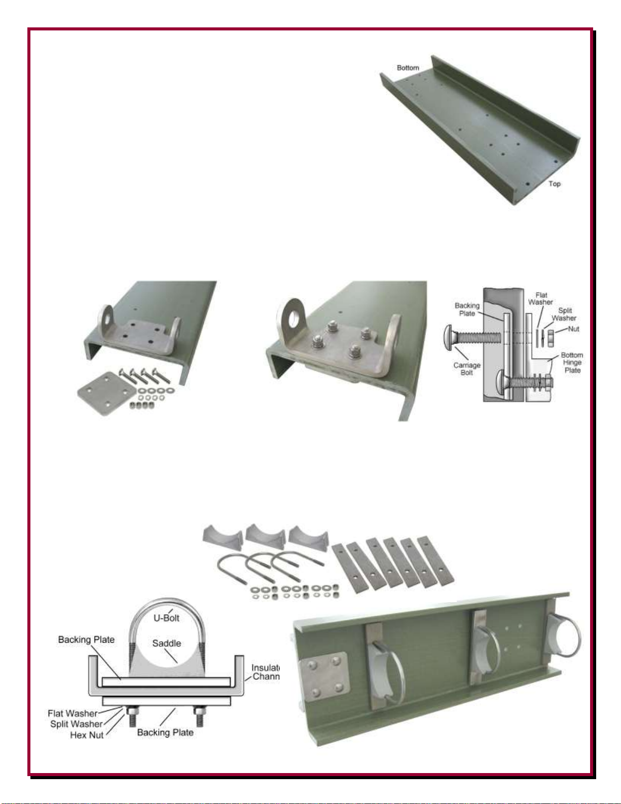
Pivot Base and Lower Antenna Assembly
1. Locate the heavy duty Extren® insulated channel.
There are 14 holes drilled in the insulated channel.
The top of the insulated channel is identified by the two
wide spaced holes located very near the top end.
2. Locate the stainless steel bottom hinge plate, backing plate, four carriage bolts, four 3/8" flat
washers, four 3/8" split lock washers and four 3/8" hex nuts. Assemble the bottom hinge to the
bottom of the heavy duty Extren® insulated channel as shown below. Tighten the hardware.
3. Locate the three 4” Cast Saddle Clamps, three 4” x 3/8” x 6.813” long stainless steel U-Bolts,
six Saddle Backing Plates, six 3/8” washers, six 3/8” split lock washers and six 3/8”-16 stainless
steel hex nuts. (Note: The U-Bolts and their hardware may be packaged separately). Loosely
assemble the U-Bolts to the heavy duty Extren® insulated channel as shown below. These will
be tightened after the base is mounted and you are ready to insert your 4” OD base element.
- 7 -

4. Locate the stainless steel pivot base locking plate, backing plate, four carriage bolts, four 3/8"
flat washers, four 3/8" split lock washers and four 3/8" hex nuts. Assemble the pivot base
locking plate to the top of the heavy duty Extren® insulated channel as shown below. Tighten
the hardware.
5. Locate the stainless steel base side bottom hinge, two 1/2"-13 x 1-3/4" long stainless steel hex
head bolts, two pivot bushings, four 1/2"x1/4" stainless steel flat washers, two 1/2" stainless
steel split lock washers, and two 1/2"-13 stainless steel hex nuts. Assemble the base side hinge
plate to the bottom hinge plate as shown below. Tighten the hardware.
- 8 -
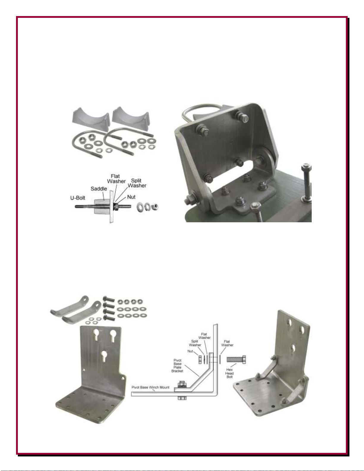
6. Locate two 3” cast saddle blocks, two stainless steel 3”x3/8”x5.25” U-Bolts, four stainless steel
3/8" flat washers, four stainless steel 3/8" split lock washers and four stainless steel 3/8"-16 hex
head nuts. (Note: The U-Bolts and their hardware may be packaged separately). Loosely
assemble (one or two threads beyond the end of the hex nuts) the two U-Bolts to the stainless
steel base side bottom hinge as shown below. The U-Bolts will be tightened in a later assembly
step.
7. Locate the stainless steel Pivot Base Winch Mount, two stainless steel Pivot Base Plate
Brackets, four 3/8"-16 x 1-3/8" long stainless steel hex bolts, eight stainless steel 3/8" flat
washers, four stainless steel 3/8" split lock washers and four stainless steel 3/8"-16 hex nuts.
Assemble the Pivot Base Plate Brackets to the Pivot Base Winch Mount as shown below.
- 9 -
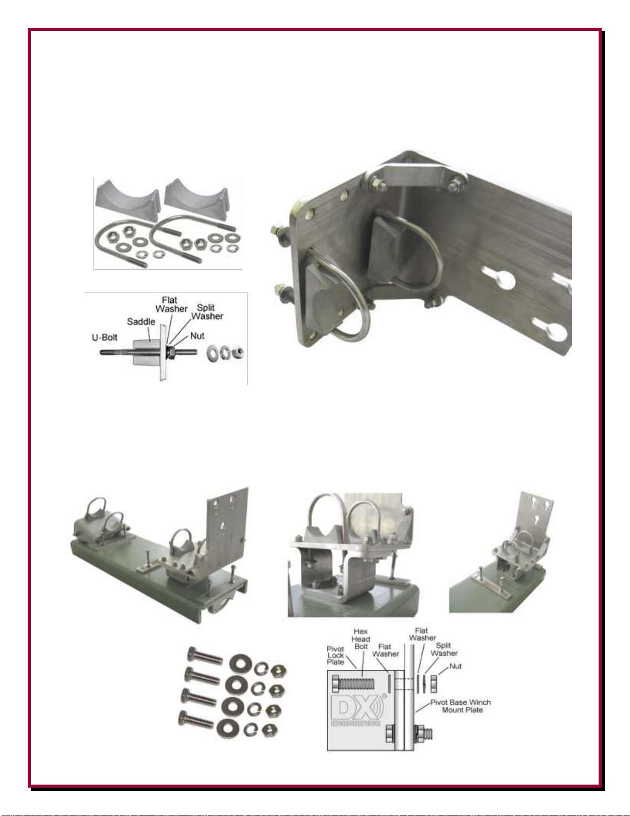
8. Locate two 3” cast saddle blocks, two stainless steel 3” x 3/8” x 5.25 long” U-Bolts, four
stainless steel 3/8" flat washers, four stainless steel 3/8" split lock washers and four stainless
steel 3/8"-16 hex head nuts. (Note: The U-Bolts and their hardware may be packaged
separately). Loosely assemble (one or two threads beyond the end of the hex nuts) the two UBolts to the Pivot Base Winch Mount as shown below. The U-Bolts will be tightened in a later
assembly step.
9. Locate four 3/8"-16 x 1-1/4" long stainless steel hex bolts, eight stainless steel 3/8" flat washers,
four stainless steel 3/8" split lock washers and four stainless steel 3/8"-16 hex nuts. Mount the
Pivot Base Winch Mount assembly to the stainless steel Pivot Base Locking Plate. Snug the
bolts, they don’t have to be real tight at this time. Note: These four bolts are removed when
using the pivoting function as described later in this manual.
- 10 -
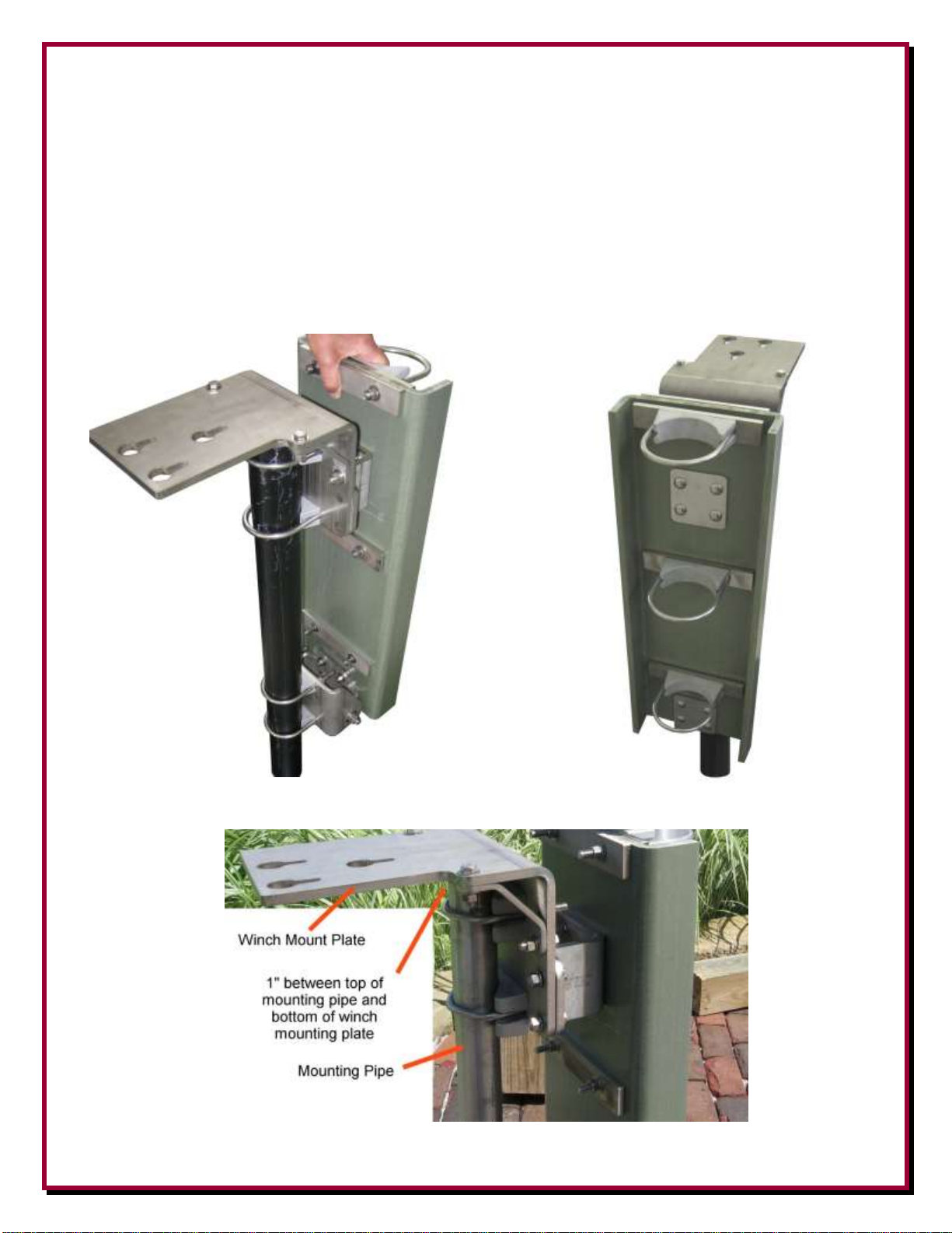
10. Move the four U-Bolts out as far as they will go (these were put on loosely in steps 2 and 8).
Slide the entire assembly onto your mounting pipe. You want approximately 1 inch clearance
from the top of your mounting pipe to the bottom side of the winch mounting plate.
Position the base fixture in the position you pre-selected for the pivoting direction.
Straighten out the U-Bolts (perpendicular to the mounting pipe) and tighten the U-Bolt clamp
hardware evenly so the length of the exposed threads is approximately equal. Any clamp should
be tightened evenly from side-to-side with an equal amount of thread above each nut.
- 11 -
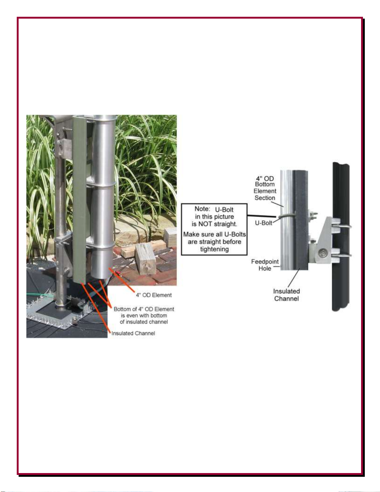
11. Using the customer supplied 4" OD antenna bottom element section. Loosen the previously
installed U-Bolts (Step 9). Insert the your 4” OD bottom element section into the antenna base
section through the three U-Bolts with the feed point at the bottom facing front as shown
below.
The bottom of your 4" OD element tube should be even with the bottom of the insulated channel
as shown below.
Tighten the U-Bolt hardware evenly so the length of the exposed threads is approximately equal.
Any clamp should be tightened evenly from side-to-side with an equal amount of thread above
each nut.
- 12 -

12. Locate the stainless steel Antenna Hook Mounting Plate, two 4” U-Bolt Saddle blocks, two 4” x
3/8” x 5.563” stainless steel U-Bolts, four stainless steel 3/8" flat washers, four stainless steel
3/8" split lock washers and four stainless steel 3/8"-16 hex head nuts. (Note: The U-Bolts and
their hardware may be packaged separately).
Loosely assemble (one or two threads beyond the end of the hex nuts) the two U-Bolts and
associated hardware to the antenna hook mounting plate as shown below. The U-Bolts will be
tightened in the next assembly step.
13. Loosen the U-Bolts enough to slide the Antenna Hook Mount assembly over your 4" OD
antenna lower element on the base assembly. Position the antenna hook mount approximately
1/2" above the insulated channel as shown below.
14. Tighten the two U-Bolt clamps hardware evenly so the length of the exposed threads is
approximately equal. Any clamp should be tightened evenly from side-to-side with an equal
amount of thread above each nut.
- 13 -
Mounting and using the Optional DXE-VRW-1 Manual Winch
1. Follow the instructions included with the optional DXE-VRW-1 - Manual Winch Add-On Kit
to prepare the Manual Winch for installation on the antenna base assembly.
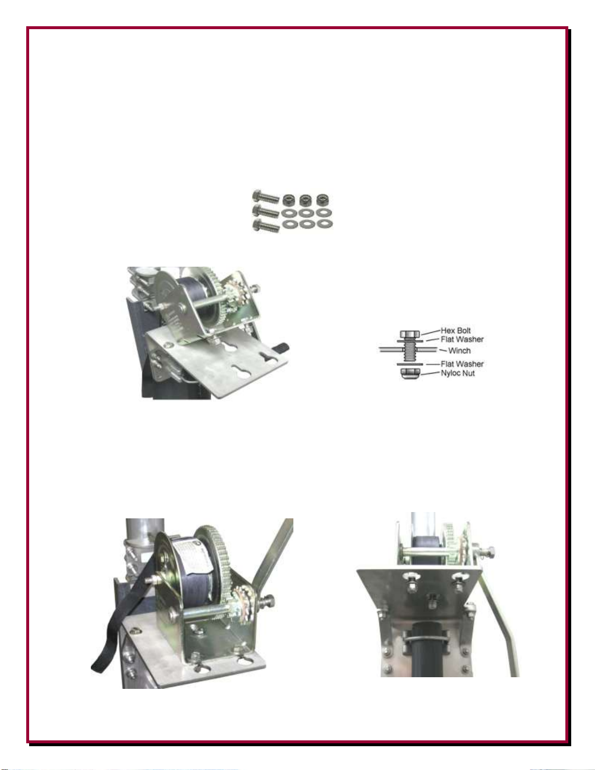
2. Included with optional DXE-VRW-1 - Manual Winch Add-On Kit is the stainless steel
hardware for mounting the winch on the pivot base assembly. The hardware includes three 3/8"16 x 1-3/8" long stainless steel hex bolts, six stainless steel 3/8"-16 flat washers and three 3/8"16 Stainless Steel Nyloc Nuts.
Loosely install the three sets of stainless steel hardware on the manual winch as shown below.
The hardware does not have to be removed from the manual winch to either install or remove
the manual winch from the winch mounting plate.
There are three holes with slots in the mounting bracket. The flat washers will fit through the
large holes. Once in place, push the winch inward (toward the antenna elements) allowing the
three bolts to go into the three slots. Tighten the hardware to hold the winch in place.
- 14 -

Connect the Hook from the manual winch strap to the Antenna Hook Mount as shown below.
To remove the winch, simply reverse this sequence.
The winch should be removed and stored when not in use. Do not leave the winch outdoors
since extended weathering and sunlight may damage or weaken the strap. Refer to the manual
that is included with the DXE-VRW-1 Manual Winch for details.
3. To lower the antenna, ensure the winch hook is in the Antenna Hook Mount. Remove the four
bolts and hardware that hold the Pivot Lock Plate to the Pivot Base Winch Mount Plate. You
can now use the winch to pivot your antenna downward.
Four Bolts to be removed to allow for pivoting
- 15 -

4. Turn the crank on the manual winch to lower, or raise the antenna. After raising your antenna
Note: Sawhorses, chairs, or ladders should be used to support the vertical sections during
assembly with the pivot base and whenever the vertical is tilted down to allow easy
maintenance, or when making adjustments.
completely, make sure you replace the four bolts that were removed in step 3. The manual
winch should be removed when not in use to protect the gears and web strap from weather and
environmental effects.
Shown with Customer Supplied Mounting Pipe, 4”
Antenna Base Section and Optional Manual Winch
Lowering or Raising the Vertical Element Assembly
1. To lower the antenna, ensure the winch hook is in the Antenna Hook Mount. Remove the four
bolts and hardware that hold the Pivot Lock Plate to the Pivot Base Winch Mount Plate. You
can now use the winch to pivot your antenna downward.
Four Bolts to be removed to allow for pivoting
- 16 -

2. To raise your antenna, ensure the winch hook is in the Antenna Hook Mount. Raise the antenna
DANGER: When raising or lowering the vertical antenna make sure you have
not inadvertently located the antenna underneath power lines.
Residential power lines are often less than 40' high.
Contact With Any Power or Utility Lines Can Be Lethal !
using the winch. Replace the four bolts and hardware that hold the Pivot Lock Plate to the Pivot
Base Winch Mount Plate.
The winch can then be removed and stored. Do not leave the winch outdoors since extended
weather and sunlight may damage or weaken the strap. Refer to the section of the manual
“Mounting and using the Optional DXE-VRW-1 Manual Winch” for detailed information.
Suggested Feedline Connection
The easiest way to make a reliable feedline connection using customer supplied coaxial cable is
using the optional DXE-RADP-3 Radial Plate with the optional DXE-112-KIT SO-239 Chassis
Mount Connector as shown in Figure F-1.
Use a customer supplied insulated wire soldered on the center pin of the chassis mounted SO-239
(14 gage insulated wire is adequate) to a ring terminal which is connected to the antenna feedpoint
hardware (See page 15). Make the wire long enough so it will not bind when raising or lowering the
antenna.
When connected in this manner, the customer supplied coaxial cable will feed the antenna and the
shield will have a positive and reliable connection to the radial field.
Figure F-1 - Feedline connection using an optional DXE-112-KIT SO-239 Chassis Mount
with the optional DXE-RADP-3 Radial Plate
- 17 -

Locking the Pivot Base
Pivot Base Assembly - US Patent No. 8,130,168
QTY
Description
1
4” Base Side Bottom Hinge
1
4” Antenna Side Bottom Hinge
2
4” Bottom Hinge Bushing
1
Heavy Duty Extren® Insulator 10” x 1/2” x 29.625”
6
Saddle Backing Plate 1.5” x .375” x 8”
1
4” Antenna Pivot Hook Mount
1
4” Pivot Base Winch Mount
2
Pivot Base Plate Bracket
1
4” Pivot Base Lock Plate
2
Backing Plate
2
4" x 3/8” x 5.563” Stainless Steel U-Bolt *
3
4" x 3/8” x 6.813” Stainless Steel U-Bolt *
5
4" Cast Saddle Clamp *
42
3/8" Flat Washer *
34
3/8" Split Lock Washer *
34
3/8-16 Nut *
8
3/8-16 x 1.375" Long, Hex Head Cap Screw
4
3" Cast Saddle *
4
3" x 3/8" x 5.25” Stainless Steel U-Bolt *
8
3/8-16 x 1-3/4" Long Stainless Steel Square Neck Carriage Bolt
2
1/2-13 x 1-3/4" Long Stainless Steel Hex Head Cap Screw
4
1/2" x 1-1/4" Stainless Steel Washer
2
1/2" Stainless Steel Lock Washer
2
1/2-13 Stainless Steel Nut
To help prevent accidental pivoting, ensure the four pivot locking bolts are in place and properly
secured. Additionally, you may replace one of the bolts with a padlock to further prevent tampering
or accidental pivoting as shown below.
Ensure all four Pivot Locking Bolts are in place
Padlock used in place of one Pivot Locking Bolt
DXE-VA-PIVOT-4 Parts List
* Note: The U-Bolts and their hardware may be packaged separately
- 18 -
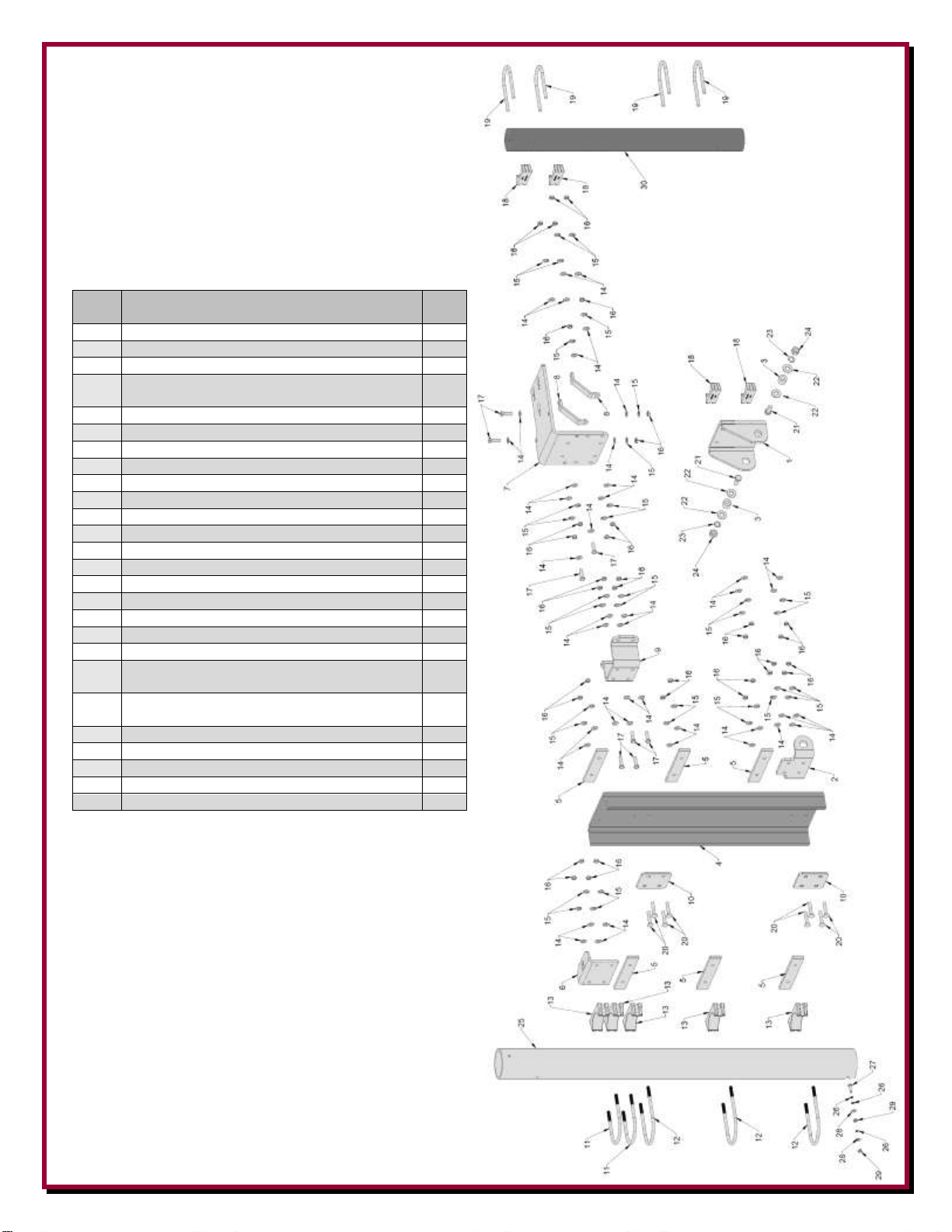
Exploded View of Pivot Base
QTY
Description
Dwg
Ref
1
4” Base Side Bottom Hinge
1
1
4” Antenna Side Bottom Hinge
2
2
4” Bottom Hinge Bushing
3
1
Heavy Duty Extren® Insulator 10” x 1/2” x
29.625”
4
6
Saddle Backing Plate 1.5” x .375” x 8”
5
1
4” Antenna Pivot Hook Mount
6
1
4” Pivot Base Winch Mount
7
2
Pivot Base Plate Bracket
8
1
4” Pivot Base Lock Plate
9
2
Backing Plate
10
2
4" x 3/8” x 5.563” Stainless Steel U-Bolt
11
3
4" x 3/8” x 6.813” Stainless Steel U-Bolt
12
5
4" Cast Saddle Clamp
13
42
3/8" Flat Washer
14
34
3/8" Split Lock Washer
15
34
3/8-16 Nut
16
8
3/8-16 x 1.375" Long, Hex Head Cap Screw
17
4
3" Cast Saddle
18
4
3" x 3/8" x 5.25” Stainless Steel U-Bolt
19
8
3/8-16 x 1-3/4" Long Stainless Steel Square Neck
Carriage Bolt
20
2
1/2-13 x 1-3/4" Long Stainless Steel Hex Head
Cap Screw
21
4
1/2" x 1-1/4" Stainless Steel Washer
22
2
1/2" Stainless Steel Lock Washer
23
2
1/2-13 Stainless Steel Nut
24
1
Customer supplied 4” OD Base Section Element
25
1
Customer supplied 3” OD mounting pipe
30
Assembly for Reference
(US Patent No. 8,130,168)
(Note: The U-Bolts and their hardware may be packaged separately)
Feedpoint hardware shown for reference
-19-
- 19 -

Suggested Parts Not Included
Optional DXE-VRW-1 Manual Winch Assembly
QTY
Description
1
1500 Pound Exposed Gear Hand Winch with Brake
3
3/8-16 x 1-3/8" long Stainless Steel Hex Bolt
8
3/8-16 Stainless Steel Flat Washer
4
3/8-16 Stainless Steel Nyloc Nut
1
Custom Polyester web strap with Hook, 2" x 15 Ft
1
3/8-16 x 3-1/2" long Grade 8 Hex Head Bolt
*UMI-81343
Anti-Seize, 1 oz. Squeeze Tube
*UMI-81464
Anti-Seize, 8.5 oz. Aerosol Can
*DXE-NSBT8
Never-Seez®, 8 oz. Brush Top
*DXE-NMBT8
Never-Seez®, 8 oz. Brush Top, Marine Grade
DXE-VRW-1 - Manual Winch Add-on Raising Kit
Manual winch add-on kit for the High Performance DX Engineering vertical antennas. The tilt fixtures for
these antennas are equipped to accept the winch directly. Allows easy raising and lowering of tall antennas
- may be easily moved from one antenna to another in multi-antenna arrays.
DXE-RADP-3 - Radial Plate (patented):
Made from Laser Cut Stainless Steel with 20 Sets of Stainless Steel Radial Attachment Hardware. The DX
Engineering Radial Plate is meant for those of you having a vertical antenna and want an easy, neat and
effective way to connect those essential radial wires to your antenna system for the highest efficiency and
strongest signals.
DXE-SSVC-3P - Stainless Steel V-Clamp for 2 to 3 inch steel pipe
This V-Clamp is made in one size that fits Steel tubing or pipe from 2 to 3'' OD as used in antenna construction.
The supplied V-bolt is long enough to attach tubing to thick plates and is made with anti-corrosive properties.
The special Stainless Steel saddle has serrated teeth will clamp to the pipe securely by biting into the
surface. For this reason, it is not recommended for softer aluminum tubing or pipe. U-Bolt thread dimensions:
3/8"-16 x 1.75". V-bolt and saddle made from high-strength 18-8 stainless steel
DXE-RADP-1HWK - Radial Plate Wire Attachment Hardware Kit - Stainless Steel
Additional 20 Sets of ALL Stainless Steel Radial Hardware for use with the DX Engineering Stainless Steel
Radial Plate.
(20) 1/4'' Bolts - (20) 1/4'' Nuts - (20) 1/4'' Flat Washers
(20) 1/4'' Split Washers - (20) 1/4'' Star Washers
UMI-81343, DXE-NSBT8 - Anti-Seize & Never-Seez®
An Anti-seize compound MUST be used on any Stainless Steel nuts, bolts, clamps or other hardware to prevent
galling and thread seizure. Any of these products can be used for this purpose.
* These products are limited to domestic UPS Ground shipping only
DXE-112-KIT Chassis Mount Coaxial Connector
DX Engineering Chassis Mount Connectors are RF connectors that provide a positive, secure connection for
your coaxial connections to you radio or antenna system. Offering high-quality Amphenol® and nonAmphenol brand SO-239 chassis mount connectors for you to choose from, with silver plated conductors and
PTFE or glass-reinforced PBT insulation to ensure the best performance for your application. SO-239 panel
mount connectors are also available and all connectors come with the correct hardware. Choose the coaxial
connectors you need the most from our selection of DX Engineering Chassis Mount Coaxial Connectors.
- 20 -

DXE-RADW - 500K or 1000K Radial Wire Kits and Components
DXE-RADW-500K
Bulk Radial Wire Kit, 500 ft Spool of Wire, 20 Lugs, 100 Staples
DXE-RADW-1000K
Bulk Radial Wire Kit, 1000 ft Spool of Wire, 40 Lugs, 200 Staples
DXE-STPL-100P
Radial Wire Anchor Pins, 100/pack
DXE-STPL-300P
Radial Wire Anchor Pins, 300/pack
To achieve optimal performance with a ground-mounted vertical, install as many radials as possible. These bulk radial
wire kits use insulated wire that is UV resistant, hard to see and lays down easily, unlike the wire that is commonly
available at the big box stores. It will last much longer in contact with soil than bare wire.
The DXE-RADW- 500K or 1000K kit provide everything you will need to build the perfect radial system!
500/1000 ft. spool of 14 AWG, stranded copper wire with vinyl insulation
20/40 lugs
100/200 radial wire anchor pins- Eliminating the need to bury your radials!
Build up to 20/40 radials, 25 feet long
DXE-225RT-20 - Ring terminal 16-14 Wire Gauge, 1/4" hole/20 Pack
\his is a set of 20 ring terminals for AWG #14 to 16 wire with a clearance hole for a 1/4" bolt. These are the
same crimp terminals supplied with the DXE Radial Wire Kits for #14 Radial and Antenna Wire.
DXE-RADW-65RT Pre-Assembled, 65 foot Radial Wires, w/ 1/4" ring Terminals, 20 Pack
The DXE-RADW-65T Radial Wire Kit include the highest quality 14 gauge stranded copper wire with a relaxed black
PVC insulation for easy installation of your radial system. This allows fast and easy installation of your radial ground
system. The stranded wire and relaxed insulation mean that the wire will lay flat as you place it on the ground - easy to
install! The twenty 65 foot pre-cut radial wires include 1/4" ring terminals professionally crimped on one end for quick
and easy attachment to the radial plate. This Radial Wire Kit is designed for users of vertical antenna systems which
have the need for a high quality radial system for optimum antenna performance. The 1/4" ring
terminals are machine crimped for maximum grip. Soldering is not required for strength, but is
recommended if installed in corrosive environments such as salt spray.
Packed 20 Radial Wires per package
14 gage, stranded copper wire
Black relaxed PVC insulation
1/4" Ring Terminal professionally crimped on each Radial Wire
DXE-STPL - Radial Wire Anchor Pins, 100/pack - No need to bury your radials!
DX Engineering Radial Wire Anchor Pins are perfect for fastening radials below the grass line to eliminate
the risk of damaging your radials during lawn maintenance.
100 count - 6'' Pins
11-Gauge
DXE-3M2155 - 3M Temflex™ 2155 Rubber Splicing Tape.
Conformable self-fusing rubber electrical insulating tape. It is designed for low voltage electrical insulating
and moisture sealing applications. For outdoor use, it should be protected from UV deterioration with an
overwrap of TRM-06132
TRM-06132 - Scotch® Super 33+.
Highly conformable super stretchy tape for all weather applications. This tape provides flexibility and easy
handling for all around performance. It also combines PVC backing with excellent electrical insulating
properties to provide primary electrical insulation for splices up to 600V and protective jacketing.
- 21 -

NOTES:
- 22 -

Technical Support
If you have questions about this product, or if you experience difficulties during the installation,
contact DX Engineering at (330) 572-3200. You can also e-mail us at:
DXEngineering@DXEngineering.com
For best service, please take a few minutes to review this manual before you call.
Warranty
All products manufactured by DX Engineering are warranted to be free from defects in material and workmanship for a
period of one (1) year from date of shipment. DX Engineering’s sole obligation under these warranties shall be to issue
credit, repair or replace any item or part thereof which is proved to be other than as warranted; no allowance shall be
made for any labor charges of Buyer for replacement of parts, adjustment or repairs, or any other work, unless such
charges are authorized in advance by DX Engineering. If DX Engineering’s products are claimed to be defective in
material or workmanship, DX Engineering shall, upon prompt notice thereof, issue shipping instructions for return to
DX Engineering (transportation-charges prepaid by Buyer). Every such claim for breach of these warranties shall be
deemed to be waived by Buyer unless made in writing. The above warranties shall not extend to any products or parts
thereof which have been subjected to any misuse or neglect, damaged by accident, rendered defective by reason of
improper installation, damaged from severe weather including floods, or abnormal environmental conditions such as
prolonged exposure to corrosives or power surges, or by the performance of repairs or alterations outside of our plant,
and shall not apply to any goods or parts thereof furnished by Buyer or acquired from others at Buyer’s specifications.
In addition, DX Engineering’s warranties do not extend to other equipment and parts manufactured by others except to
the extent of the original manufacturer’s warranty to DX Engineering. The obligations under the foregoing warranties
are limited to the precise terms thereof. These warranties provide exclusive remedies, expressly in lieu of all other
remedies including claims for special or consequential damages. SELLER NEITHER MAKES NOR ASSUMES ANY
OTHER WARRANTY WHATSOEVER, WHETHER EXPRESS, STATUTORY, OR IMPLIED, INCLUDING
WARRANTIES OF MERCHANTABILITY AND FITNESS, AND NO PERSON IS AUTHORIZED TO ASSUME
FOR DX ENGINEERING ANY OBLIGATION OR LIABILITY NOT STRICTLY IN ACCORDANCE WITH THE
FOREGOING.
©DX Engineering 2012
DX Engineering®, DXE®, DX Engineering, Inc.® , Hot Rodz®, Maxi-Core®, DX Engineering THUNDERBOLT™, DX
Engineering Yagi Mechanical®, EZ-BUILD®, TELREX® and Gorilla Grip® Stainless Steel Boom Clamps, are
trademarks of PDS Electronics, Inc. No license to use or reproduce any of these trademarks or other trademarks is given
or implied. All other brands and product names are the trademarks of their respective owners.
Specifications subject to change without notice.
- 23 -
 Loading...