

UNUN Bracket Kit for the
DXE-MBVE-5A
Vertical Antenna
DXE-UN-BRKT-5A
(US Patent No. D597,086)
DXE-UN-BRKT-5A-INS Revision 0c
Shown with DXE-UN-43 installed
© DX Engineering 2021
1200 Southeast Ave. - Tallmadge, OH 44278 USA
Phone: (800) 777-0703 ∙ Tech Support and International: (330) 572-3200
Fax: (330) 572-3279 ∙ E-mail: DXEngineering@DXEngineering.com
- 1 -
Introduction
The DXE-UN-BRKT-5A UNUN Bracket Kit is designed specifically for use with the proven
Maxi-Core® Technology DXE-UN-43 UNUN for mounting on a DX Engineering MBVE-5A
Multi-Band Vertical. The DXE-MBVE-5A installation manual has these instructions plus additional
detailed information on feedline connections specific to the DXE-MBVE-5A antenna.
Note: JTL-1255 Jet-Lube SS-30 Anti-Seize must be used on all clamps, bolts and stainless steel
threaded hardware to prevent galling and to ensure proper tightening.
A DXE-UN-43 UNUN is required.
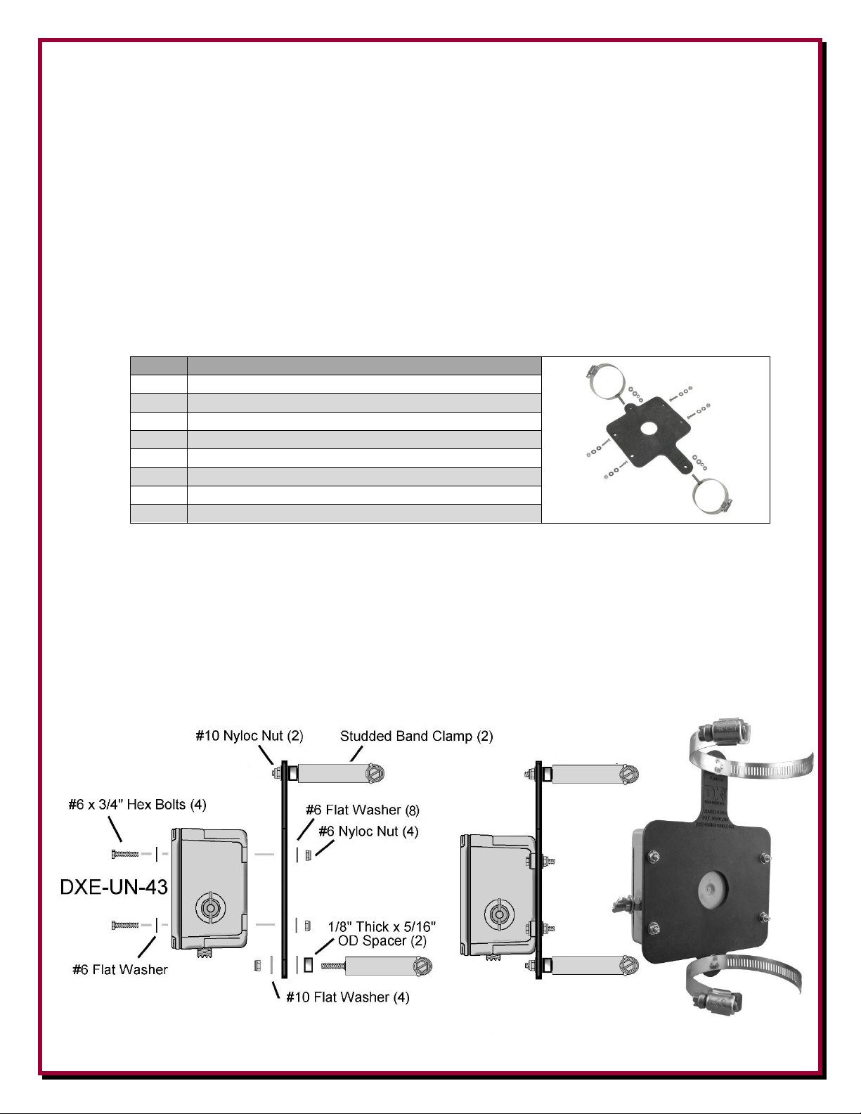
DXE-UN-BRKT-5A
Qty
Description
1
Mounting Bracket - (US Patent No. D597,086)
4
# 6 x 3/4" long Stainless Steel Hex Head Bolts
8
# 6 Stainless Steel Flat Washer
4
# 6 Stainless Steel Nyloc Nut
2
2-1/2” Studded Element Clamp
2
# 10 Stainless Steel Nyloc Hex Nut
4
# 10 Stainless Steel Flat Washer
2
# 10 Spacer, Aluminum, 3/8” x 9/16” long
Assembling the DXE-UN-BRKT-5A UNUN Mounting Bracket &
UNUN Installation
Using the #6 hardware, attach the optional DXE-UN-43 UNUN to the patented DXE-UN-BRKT
UNUN Bracket with the SO-239 connector as shown below. Tighten the Nyloc Nuts so they are
snug. Do not over tighten since the mounting tabs on the UNUN are plastic.
Attach the 2-1/2” stainless steel studded element clamps to the UNUN Bracket as shown below.

- 2 -
Installation of UNUN Assembly to DXE-MBVE-5A Lower Section
Position the UNUN and
mounting bracket so the
bottom element clamp is
located Just above the
feedpoint hardware as
shown. With the UNUN
facing the front, tighten the
element clamps to hold the
assembly in place.
MBVE-5A Feedline Connections
The UNUN has two 1/4-20 connection points and have Wing Nuts and Flat Washers used for
connecting the DXE-MBVE-5A feed wires to the feedpoint and grounding
system on the DXE-MBVE-5A antenna.
The DXE-UN-43 UNUN is attached to the feedline antenna connection
using one 6” wire with ring terminals and one 7” wire with ring terminals.
Connect the 6” wire with terminals from the antenna feedpoint located on
the antenna element to the terminal on the DXE-UN-43 UNUN closest to
the Red "+" on the label as shown below. Do not over tighten the wing
nuts. Hand tighten them only, do not use pliers or other tools to over tighten the wing nuts.
Connect the other 7" wire with ring
terminals from the terminal on the
DXE-UN-43 UNUN closest to the
Black "▬" on the label to the
bolt on the angle plate as shown.
Your coaxial cable from the radio
connects direct to the SO-239
connector on the DXE-UN-43
UNUN. Weatherproof this coaxial
connection using 3M Temflex™
2155 Rubber Splicing Tape and an
overwrap of 3M Scotch® Super 33+.

- 3 -
Tuning the Vertical Antenna System
The use of a customer supplied, high quality, wide range outboard tuner is required for any multiband trapless vertical antenna system. The tuner should be capable of tuning the wide range of
impedances presented by the antenna and coaxial cable at all the operating frequencies. Tuners of
this type generally have a good quality variable roller inductor and at least one large variable
capacitor for fine tuning. Tuners which are built into transceivers, lack sufficient impedance tuning
range for this type of high performance vertical antenna system.
The actual impedance of the multi-band antenna is affected by local conditions, including proximity
to structures, other antennas, number of radials, or personal preference for the mounting location. It
may be necessary to adjust the top element section slightly longer or shorter, or to vary the length of
the coaxial cable, if tuning to best SWR is not achieved with your tuner on all bands.
The performance of this versatile, rugged antenna is highly dependent on the ability of your tuner to
deliver a low SWR when tuned. Refer to your tuner user's manual for correct tuner operation.
Manual Updates
Every effort is made to supply the latest manual revision with each product. Occasionally a manual
will be updated between the time your DX Engineering product is shipped and when you receive it.
Please check the DX Engineering web site (www.DXEngineering.com) for the latest manual
revision.
Technical Support
If you have questions about this product, or if you experience difficulties during the installation,
contact DX Engineering at (330) 572-3200. You can also e-mail us at:
DXEngineering@DXEngineering.com
For best service, please take a few minutes to review this manual before you call.
Warranty
All products manufactured by DX Engineering are warranted to be free from defects in material and workmanship for a period of one (1) year from
date of shipment. DX Engineering’s sole obligation under these warranties shall be to issue credit, repair or replace any ite m or part thereof which is
proved to be other than as warranted; no allowance shall be made for any labor charges of Buyer for replacement of parts, adjustment or repairs, or
any other work, unless such charges are authorized in advance by DX Engineering. If DX Engineering’s products are claimed to be defective in
material or workmanship, DX Engineering shall, upon prompt notice thereof, issue shipping instructions for return to DX Engineering (transportationcharges prepaid by Buyer). Every such claim for breach of these warranties shall be deemed to be waived by Buyer unless made in writing. The above
warranties shall not extend to any products or parts thereof which have been subjected to any misuse or neglect, damaged by accident, rendered
defective by reason of improper installation, damaged from severe weather including floods, or abnormal environmental conditions such as prolonged
exposure to corrosives or power surges, or by the performance of repairs or alterations outside of our plant, and shall not apply to any goods or parts
thereof furnished by Buyer or acquired from others at Buyer’s specifications. In addition, DX Engineering’s warranties do not extend to other
equipment and parts manufactured by others except to the extent of the original manufacturer’s warranty to DX Engineering. The obligations under
the foregoing warranties are limited to the precise terms thereof. These warranties provide exclusive remedies, expressly in lieu of all other remedies
including claims for special or consequential damages. SELLER NEITHER MAKES NOR ASSUMES ANY OTHER WARRANTY
WHATSOEVER, WHETHER EXPRESS, STATUTORY, OR IMPLIED, INCLUDING WARRANTIES OF MERCHANTABILITY AND
FITNESS, AND NO PERSON IS AUTHORIZED TO ASSUME FOR DX ENGINEERING ANY OBLIGATION OR LIABILITY NOT STRICTLY
IN ACCORDANCE WITH THE FOREGOING.
©DX Engineering 2021
DX Engineering®, DXE®, DX Engineering, Inc.®, Hot Rodz®, Maxi-Core®, DX Engineering THUNDERBOLT®, DX Engineering Yagi
Mechanical®, EZ-BUILD®, TELREX®, Gorilla Grip® Stainless Steel Boom Clamps, Butternut®, SkyHawk™, SkyLark™, SecureMount™,
OMNI-TILT™, RF-PRO-1B®, AFHD-4® are trademarks of PDS Electronics, Inc. No license to use or reproduce any of these trademarks or other
trademarks is given or implied. All other brands and product names are the trademarks of their respective owners.
Specifications subject to change without notice.
 Loading...