


1-of-8 Control Console
DXE-EC-8
DXE-EC-8-INS-Revision 1a
DX Engineering 2017
1200 Southeast Ave. - Tallmadge, OH 44278 USA
Phone: (800) 777-0703 Technical Support and International: (330) 572-3200
Fax: (330) 572-3279 E-mail: DXEngineering@DXEngineering.com
- 1 -
Introduction
The DXE-EC-8 is a flexible 8 position controller used to control the DX Engineering RR8A series antenna
switches or any other product that uses a 12 to 24 Vdc 1-of-8 control format.
The DXE-EC-8 offers the following features:
Stainless Steel Housing
Non-Skid feet
On-Off toggle switch
Green LED indicates power is applied
Filter capacitors on each line
Internal automatic resettable fuse
Includes a 2.1 mm power plug for DC power connection
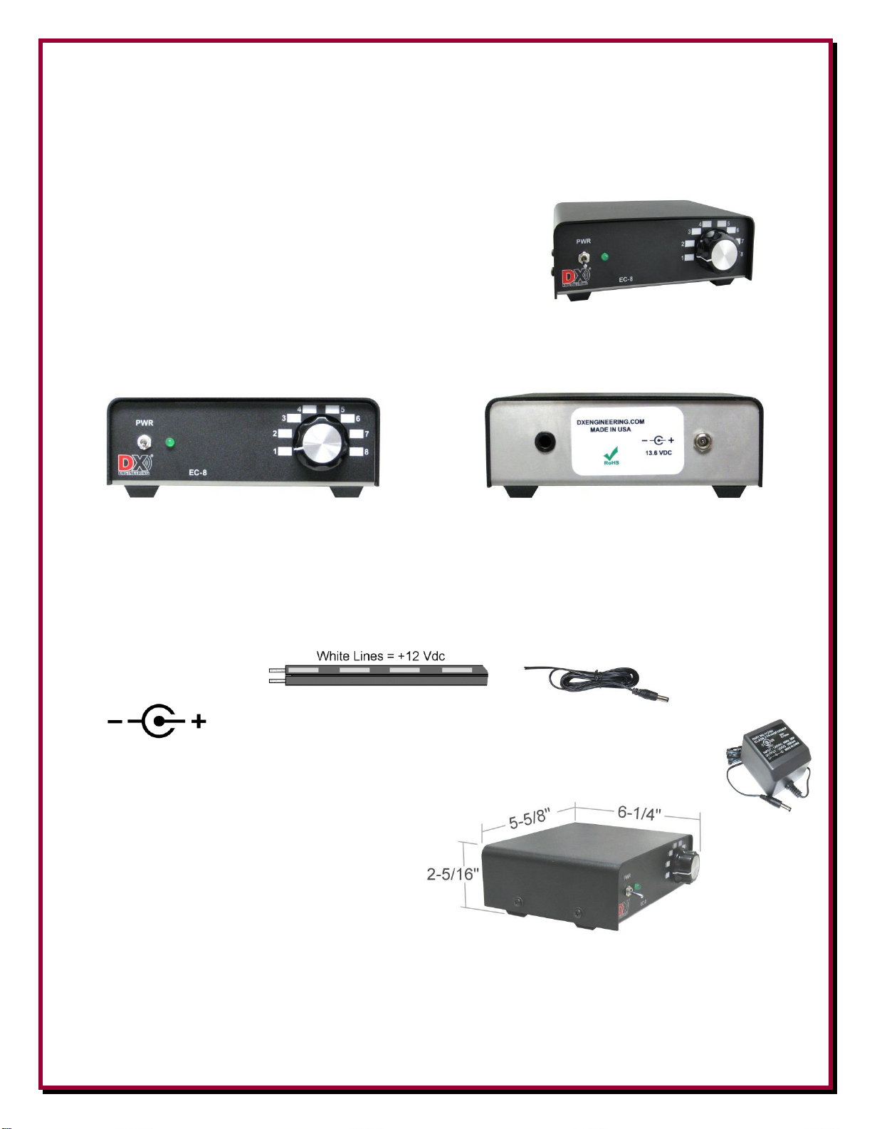
Front and Rear Panels
On/Off toggle switch Control Wire Feed Through
Green LED Power Connection
8 Position Rotary Switch
The DC Input used in most applications will be +12 Vdc. You can input up to 24 Vdc if your
application requires 24 Vdc switching. A 2.1 mm power cord is supplied with unit. The wire with
the white stripes is the +12 Vdc.
Outer Connection is GROUND, Center Pin is +12 VDC.
If station power is used, it must be +12 Vdc at 1 amp (fused) minimum. An optional
DXE-PSW-12D1A 120 Vac 60 Hz to 12 Vdc 1 Amp, fused wall transformer supply is
available.
Tools Required
Phillips Head Screwdriver
Wire Stripper
Small Flat Blade Screwdriver
Overall Size
Interior Connections
1. Open the unit by removing the four (two per side) Phillips head screws to remove the cover.
- 2 -

2. Push the end of the cable through the control wire feed through on the rear of the unit.
Connector Wire Reference Chart
G 1 2 3 4 5 6 7 8
G
3. Connections for the wire are made on header "H1". Loosen each terminal screw until it is near
flush with the top of the connector block as shown below.
4. Strip approximately 1/4" insulation from the 9 conductor wire ends
as shown to the right.
5. Connect each wire to a terminal by sliding the wire completely into the wire connection hole.
Using a small flat blade screwdriver, tighten the associated screw until the wire is firmly
gripped in place as shown below.
Take caution to ensure just the wire is clamped in place, not the wire's insulation which would cause an open
or intermittent connection. Do not over tighten the screw so much that the wire is cut instead of being firmly
gripped. Use the included Tye-Wrap on the inside of the unit to hold the cable from pulling outward as
shown above.
DXE-CW9S Shielded cable is recommended. The drain wire (bare wire) is used as the signal ground return.
Both of the "G" connections are internally tied together. When connecting the cable to the DXE-EC-8,
ensure your cable is wired the same way at the other end to avoid un-necessary troubleshooting. Use the
chart below to record which color wire is connected to each terminal connection. The selected position will
supply the DC voltage that is connected to the DXE-EC-8.
Control lines (usually BCD ) can normally use good quality CAT5e cable (4 twisted pairs of 24 AWG wire)
for runs up to 1000 feet. Typical DX Engineering BCD control lines requirements are +12 VDC at 25
milliamps. Depending on the number of control lines needed (usually 3 or 4) you can double up the twisted
pairs of CAT5e cable, or use control wire that is at least 22 AWG, allowing runs up to 1500 feet. If you use a
cable with more conductors, it is a good idea to tie the unused conductors to ground. For longer runs of
control cable, use a line loss calculator to ensure you supply the proper control levels needed.
- 3 -

Approximate BCD Control Line Lengths.
Minimum Copper
Wire Gage (AWG)
Length
24
1,000 feet
22
1,500 feet
20
2,000 feet
Optional Items
DXE-CW9S - Shielded Control Wire, 9 conductor stranded, per foot
DXE-CW9S is a high quality shielded outdoor cable. It features 9 copper #24 AWG stranded conductors with
aluminum foil shielding plus a #24 stranded tinned copper drain wire. This gives you 8 switch positions plus
common ground - plus the separate shield. It has a gray PVC jacket. This cable is ideal for DX Engineering Remote
Antenna Switches and Four Square arrays, and should be considered for any low-current custom remote switching
application you have - such as receiving antenna arrays. Order by the foot in the length you require. Price shown is
per foot. A nice feature is the "rip cord", which allows for easy stripping of the heavy jacket without worry about nicking or
accidentally cutting the conductors.
AC Adapter 12VDC/1000mA - DXE-PSW-12D1A
The DXE-PSW-12D1A is an AC Wall Transformer Adapter to furnish 12 Volts DC at 1000 mA from 120 Vac 60 Hz
input, fused output. It features a standard 2.1 mm plug connection for 12 Vdc. Outer connection is GROUND Center
Pin is input for +12 VDC. Ideal separate power source for DX Engineering Antenna Switch and Transmit Four Square
Controllers, NCC-1, TVSU, DXE-MBV-ATU-1 Remote Antenna Tuner Kit and most MFJ automatic antenna tuners
Technical Support
If you have questions about this product, or if you experience difficulties during the installation, contact DX
Engineering at (330) 572-3200. You can also e-mail us at:
DXEngineering@DXEngineering.com
For best service, please take a few minutes to review this manual before you call.
Warranty
All products manufactured by DX Engineering are warranted to be free from defects in material and workmanship for a period of one (1) year from
date of shipment. DX Engineering’s sole obligation under these warranties shall be to issue credit, repair or replace any item or part thereof which is
proved to be other than as warranted; no allowance shall be made for any labor charges of Buyer for replacement of parts, adjustment or repairs, or
any other work, unless such charges are authorized in advance by DX Engineering.
If DX Engineering’s products are claimed to be defective in material or workmanship, DX Engineering shall, upon prompt notice thereof, issue
shipping instructions for return to DX Engineering (transportation-charges prepaid by Buyer). Every such claim for breach of these warranties shall be
deemed to be waived by Buyer unless made in writing. The above warranties shall not extend to any products or parts thereof which have been
subjected to any misuse or neglect, damaged by accident, rendered defective by reason of improper installation, damaged from severe weather
including floods, or abnormal environmental conditions such as prolonged exposure to corrosives or power surges, or by the performance of repairs or
alterations outside of our plant, and shall not apply to any goods or parts thereof furnished by Buyer or acquired from others at Buyer’s specifications.
In addition, DX Engineering’s warranties do not extend to other equipment and parts manufactured by others except to the extent of the original
manufacturer’s warranty to DX Engineering.
The obligations under the foregoing warranties are limited to the precise terms thereof. These warranties provide exclusive remedies, expressly in lieu
of all other remedies including claims for special or consequential damages. SELLER NEITHER MAKES NOR ASSUMES ANY OTHER
WARRANTY WHATSOEVER, WHETHER EXPRESS, STATUTORY, OR IMPLIED, INCLUDING WARRANTIES OF MERCHANTABILITY
AND FITNESS, AND NO PERSON IS AUTHORIZED TO ASSUME FOR DX ENGINEERING ANY OBLIGATION OR LIABILITY NOT
STRICTLY IN ACCORDANCE WITH THE FOREGOING.
©DX Engineering 2017
DX Engineering®, DXE®, DX Engineering, Inc.®, Hot Rodz®, Maxi-Core®, DX Engineering THUNDERBOLT®, DX Engineering Yagi Mechanical®,
EZ-BUILD®, TELREX®, Gorilla Grip® Stainless Steel Boom Clamps, Butternut®, SkyHawk™, SkyLark™, SecureMount™, OMNI-TILT™, RF-
PRO-1B®, AFHD-4® are trademarks of PDS Electronics, Inc. No license to use or reproduce any of these trademarks or other trademarks is given or
implied. All other brands and product names are the trademarks of their respective owners.
Specifications subject to change without notice.
- 4 -
 Loading...